
PLAN THE INSTALLATION
This chime will accomodate up to three (3) entrances. Pushbuttons connected to the “FRONT” terminal play a
4 or 8 note melody. Pushbuttons connected to the “SIDE” and “REAR” terminals play separate single notes. In
order to cycle through the 4 or 8-note melody, the chime must have a constant source of power.
NEW CONSTRUCTION INSTALLATIONS (Figure 1)
The transformer provides constant power to terminals 2 and 3 and also provides power to light the pushbut-
tons.
REPLACING AN EXISTING 2-NOTE CHIME (Figure 2)
Two 9-volt batteries provide cosntant power to the chime, while the transformer provides power to light the
pushbuttons.
INSTALLATION
ALL ELECTRICAL WORK MUST BE DONE IN ACCORDANCE WITH LOCAL AND/OR NATIONAL ELECTRICAL CODE
AS APPLICABLE.
TURN OFF POWER AT SERVICE ENTRANCE BEFORE
INSTALLING, WIRING, OR SERVICING THIS PRODUCT.
1. Hold chime mechanism against wall and mark four
(4) mounting holes.
2. Drill 3/16” holes where marked and tap in wall
anchors from parts bag.
3. Bring wiring through access hole(s) in chime
mechanism backplate.
4. Loosely attach chime mechanism to wall with
screws from parts bag.
5. Tighten screws securely.
6. Connect wires to appropriate terminals. Refer to
Figure 1 for new construction or Figure 2 if replac-
ing an existing 2-note chime. Install two (2) alkaline
9-volt batteries, if appropriate for your application.
7. Turn on power at service entrance. Make sure push-
buttons operate chime properly. (Adjust switch on
circuit board for 4 or 8 chime tones at front door.
Side and rear doors will have 1 chime tone each.)
8. Hook cover over chime mechanism.
DO NOT OIL CHIME PLUNGERS.
Oil will cause them to stick during operation. If
plungers fail to operate freely due to accumulation of
dust, cooking grease, etc., clean with a non-flammable
cleaning solvent which will evaporate, leaving a dry
surface.
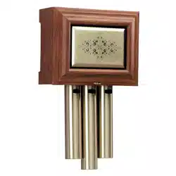
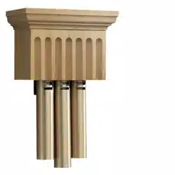
THREE NOTE DOOR CHIME
READ AND SAVE THESE INSTRUCTIONS
BATTERY
HOLDERS
WIRING
ACCESS
HOLE
MOUNTING
HOLES
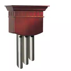
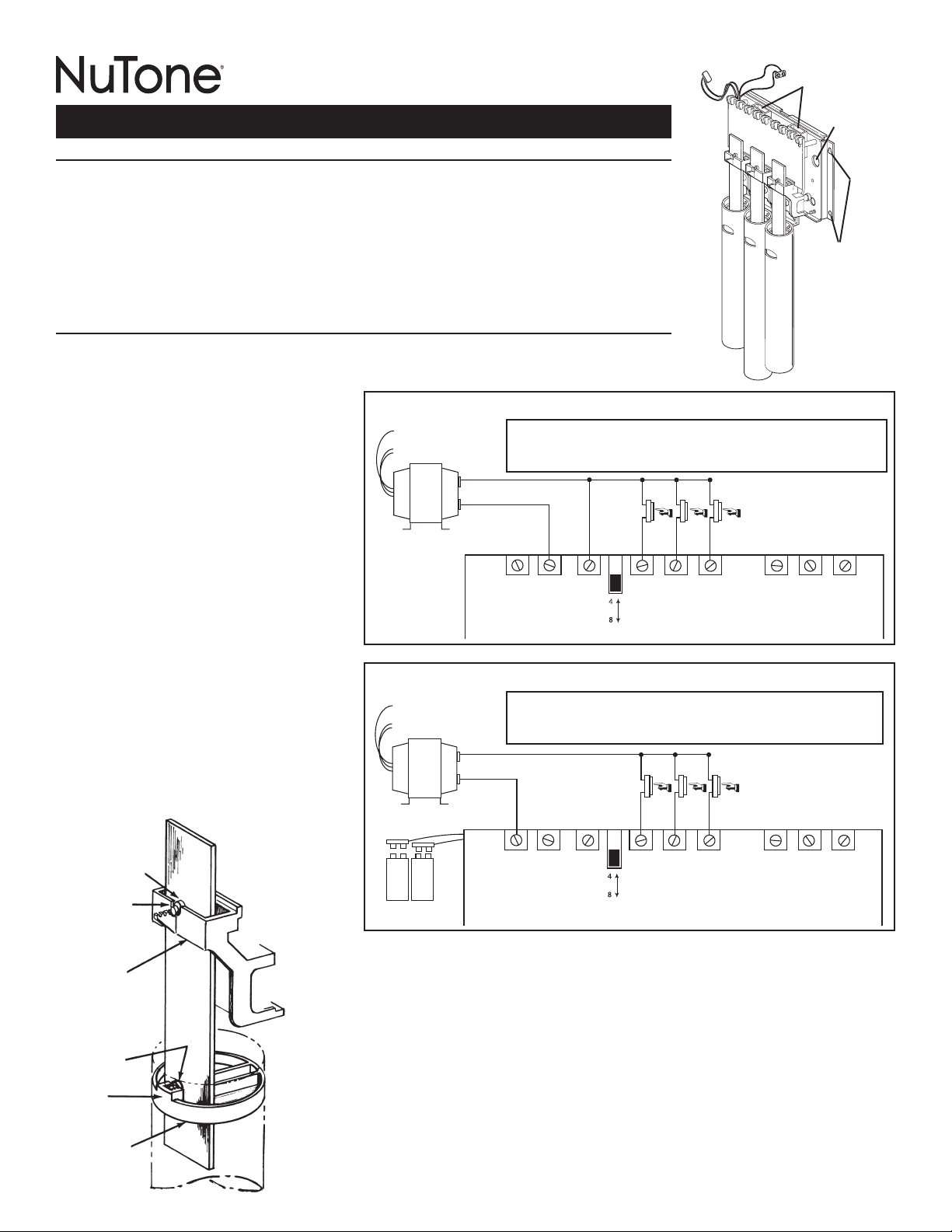
CHIME BAR INSTALLATION (Figure 3)
The three (3) chime bars must be held freely, within the decorative tubes, in order to achieve and
sustain the proper chime tone. When the chime bars are properly assembled to the mechanism, it
should be possible to move each bar up and down slightly without moving the isolators.
In the event that the chime bars become dislodged during shipping, refer to the instructions below
to properly reset them in the tubes.
1. The upper chime bar isolator should be completely seated in the U-shaped opening of the
chime bar holder.
2. The lower chime bar isolator should be inside the holder of the top tube plug.
UPPER
CHIME BAR
ISOLATOR
U-SHAPED
OPENING
CHIME BAR
HOLDER
LOWER
CHIME BAR
ISOLATOR
HOLDER
TOP TUBE
PLUG
SLIGHT UP AND
DOWN BAR
MOVEMENT
SHOULD BE
POSSIBLE
↕
RECOMMENDED NEW CONSTRUCTION WIRING
F S R 1 2 3
Lighted or
Unlighted Buttons
Front Side Rear
Ground
120 VAC
16 VAC
Transformer
NOT USED
Volume Control
9-volt
batteries
not used
OPTIONAL: 2 or 3 chimes can be connected to a single transformer. 2 chimes require
transformer Model C909 or C907. 3 chimes require transformer Model C907.
(Figure 1)
REPLACING EXISTING 2-NOTE CHIME
F S R 1 2 3
Lighted or
Unlighted Buttons
9V 9V
Front Side Rear
Ground
120 VAC
16 VAC
Transformer
Requires Two
9-volt Batteries
NOT USED
Volume Control
OPTIONAL: 2 or 3 chimes can be connected to a single transformer. 2 chimes require
transformer Model C909 or C907. 3 chimes require transformer Model C907.
(Figure 2)
(Figure 3)
Tube
configurations
vary by model.
To register this product, visit: www.nutone.com
PLANIFICATION DE L’INSTALLATION
Ce carillon peut accommoder jusqu’à trois (3) entrées. Les boutons de sonnette branchés à la borne « AVANT
» jouent une mélodie à 4 ou 8 notes. Les boutons branchés aux bornes « CÔTÉ » et « ARRIÈRE » jouent des
notes simples. Pour jouer successivement les 4 ou 8 notes d’une mélodie, le carillon doit posséder une source
d’alimentation constante.
CONSTRUCTIONS NEUVES (Figure 1)
Le transformateur fournit une alimentation constante aux bornes 2 et 3 ainsi qu’aux lumières des boutons de sonnette.
REMPLACEMENT D’UN CARILLON À 2 NOTES (Figure 2)
Deux piles de 9 volts fournissent une alimentation constante au carillon, alors que le transformateur permet
d’illuminer les boutons de sonnette.
INSTALLATION
TOUTES LES CONNEXIONS ÉLECTRIQUES DOIVENT ÊTRE CONFORMES AUX CODES ET RÈGLEMENTS MUNICIPAUX EN VIGUEUR
OU AU CODE NATIONAL DE L’ÉLECTRICITÉ, LE CAS ÉCHÉANT.
COUPEZ LE COURANT AU PANNEAU ÉLECTRIQUE AVANT D’INSTALLER, DE BRANCHER OU DE RÉPARER CE PRODUIT.
1. Tenez le mécanisme du carillon contre le mur et marquez
les quatre (4) trous de fixation.
2. Percez des trous de 4 mm (3/16 po) aux endroits marqués
et enfoncez les chevilles d’ancrage se trouvant dans le sac
de pièces.
3. Enfilez les fils dans le(s) trou(s) d’accès de la plaque arrière
du mécanisme du carillon.
4. Fixez le mécanisme du carillon au mur avec les vis se
trouvant dans le sac de pièces.
5. Serrez fermement les vis.
6. Branchez les fils aux bornes appropriées. Consultez la
figure 1 dans le cas d’une construction neuve ou la figure
2 s’il s’agit de remplacer un carillon à 2 notes. Installez
deux (2) piles alcalines de 9 volts, si cela correspond à
votre application.
7. Rétablissez le courant sur le panneau d’alimentation
électrique. Vérifiez si tous les boutons de sonnette
déclenchent correctement le carillon. (Réglez le
commutateur du circuit imprimé pour obtenir une mélodie
à 4 ou à 8 notes pour la porte avant. Les portes du côté et
de l’arrière auront un carillon à une seule note chacune.)
8. Replacez le couvercle sur le mécanisme du carillon.
NE HUILEZ PAS LES PISTONS PLONGEURS DU CARILLON.
L’huile entraînera leur collage lors du fonctionnement. Si les
pistons plongeurs ne fonctionnent pas librement en raison
d’une accumulation de poussière, de graisse de cuisson, etc.,
nettoyez-les avec un solvant ininflammable qui s’évapore,
laissant la surface sèche.
CARILLON DE PORTE À TROIS NOTES
VEUILLEZ LIRE CES DIRECTIVES ET LES CONSERVER
LOGEMENTS
DES PILES
TROU
D’ACCÈS
DES FILS
TROUS DE
FIXATION
INSTALLATION DES LAMES DE CARILLON (Figure 3)
Les trois (3) lames de carillon doivent pendre librement à l’intérieur des tubes décoratifs afin de
produire et de soutenir la note adéquate. Lorsque les lames de carillon sont bien assemblées
dans le mécanisme, chacune peut bouger légèrement de haut en bas sans remuer les isolateurs.
Si les lames de carillon sont délogées lors du transport, consultez les instructions au-dessous
pour les replacer correctement dans les tubes.
1. L’isolateur supérieur de la lame de carillon doit être complètement appuyé dans l’ouverture en
U du support de lame de carillon.
2. L’isolateur inférieur de la lame de carillon doit être à l’intérieur du support du bouchon supérieur
du tube.
CÂBLAGE RECOMMANDÉ POUR CONSTRUCTION NEUVE
F S R 1 2 3
Volume Control
Boutons illuminés
ou non illuminés
Avant Côté Arrière
Fil de terre
120 VCA
Transformateur
16 VCA
NON UTILISÉ
OU
NOTES
Piles de
9 volts non
utilisées
FACULTATIF : 2 ou 3 carillons peuvent être raccordés à un même transformateur.
Pour 2 carillons, utilisez un transformateur de modèle C909 ou C907. Pour 3
carillons, utilisez un transformateur de modèle C907.
(Figure 1)
REMPLACEMENT D’UN CARILLON À 2 NOTES
F S R 1 2 3
Boutons illuminés
ou non illuminés
9 V 9 V
Avant Côté Arrière
Fil de terre
120 VCA
Transformateur
16 VCA
Exige deux
piles de 9 volts
NON UTILISÉ
Volume Control
OU
NOTES
FACULTATIF : 2 ou 3 carillons peuvent être raccordés à un même
transformateur. Pour 2 carillons, utilisez un transformateur de modèle C909 ou
C907. Pour 3 carillons, utilisez un transformateur de modèle C907.
(Figure 2)
ISOLATEUR
SUPÉRIEUR
DE LAME DE
CARILLON
OUVERTURE
EN U
SUPPORT
DE LAME DE
CARILLON
ISOLATEUR
INFÉRIEUR
DE LAME DE
CARILLON
SUPPORT
BOUCHON
SUPÉRIEUR
DU TUBE
UN LÉGER
MOUVEMENT
DE HAUT EN
BAS DOIT ÊTRE
POSSIBLE
↕
(Figure 3)
La
configuration
des tubes
varie selon le
modèle.
Pour enregistrer ce produit, visitez: www.nutone.ca

PLANEACIÓN DE LA INSTALACIÓN
Este timbre aceptará hasta tres (3) entradas. Los botones conectados en la terminal “DELANTERA” reproducen
una melodía de 4 u 8 notas. Los botones conectados a las terminales “LATERAL” y “TRASERA” reproducen
notas individuales por separado. Para ciclar por la melodía de 4 u 8 notas, el timbre debe tener una fuente de
alimentación eléctrica constante.
INSTALACIONES PARA UNA NUEVA CONSTRUCCIÓN (Figura 1)
El transformador provee alimentación eléctrica constante a las terminales 2 y 3 y también para iluminar los
botones.
CÓMO REEMPLAZAR UN TIMBRE DE 2 NOTAS YA EXISTENTE (Figura 2)
Dos baterías de 9 voltios proveen alimentación eléctrica constante al timbre, mientras que el transformador ilumina
los botones.
INSTALACIÓN
TODO EL TRABAJO ELÉCTRICO DEBE REALIZARSE DE ACUERDO CON LOS CÓDIGOS ELÉCTRICOS LOCALES O NACIONALES
CORRESPONDIENTES.
APAGUE EL SUMINISTRO ELÉCTRICO EN LA ENTRADA DEL
SERVICIO ANTES DE INSTALAR, CABLEAR O DAR SERVICIO
A ESTE PRODUCTO.
1. Sostenga el mecanismo del timbre contra la pared y
marque cuatro (4) agujeros de montaje.
2. Perfore orificios de 4 mm (3/16 de pulg.) en los lugares
marcados e inserte los taquetes/anclas incluidos en la
bolsa de piezas.
3. Pase los cables eléctricos a través de los orificios de
acceso que están en la placa trasera del mecanismo del
timbre.
4. Sujete holgadamente el mecanismo del timbre a la pared
con los tornillos incluidos en la bolsa de piezas.
5. Apriete bien los tornillos.
6.
Conecte los cables a las terminales apropiadas. Consulte
la Figura 1 si es una construcción nueva o la Figura 2 si
reemplaza un timbre existente de 2 notas. Instale dos (2) pilas
alcalinas de 9 voltios, si es apropiado para su aplicación.
7. Encienda la energía eléctrica en la entrada de servicio.
Asegúrese de que los botones operan el timbre
correctamente. (Ajuste el interruptor del tablero de
circuitos para los 4 u 8 tonos del timbre en la puerta
delantera. Las puertas lateral y trasera tendrán 1 tono de
timbre cada una.)
8.
Enganche y coloque la tapa sobre el mecanismo del timbre.
NO ENGRASE LOS ÉMBOLOS DE LOS TIMBRES.
La grasa hará que se peguen durante su funcionamiento.
Si los émbolos no pueden moverse libremente debido a la
acumulación de polvo, aceite de cocina, etc., límpielos con
un solvente de limpieza no flamable que se evaporará y dejará
una superficie seca.
TIMBRE DE PUERTA DE TRES NOTAS
LEA Y CONSERVE ESTAS INSTRUCCIONES
SOPORTES
DE LAS PILAS
ORIFICIO
DE ACCESO
DE LOS
CABLES
ORIFICIOS
DE MONTAJE
INSTALACIÓN DE BARRA DEL TIMBRE (Figura 3)
Las tres (3) barras del timbre deben poder moverse libremente dentro de los tubos decorativos,
con el fin de lograr y mantener el tono de timbre apropiado. Cuando las barras del timbre están
instaladas correctamente en el mecanismo, debe ser posible mover ligeramente cada barra hacia
arriba y hacia abajo sin mover los aislantes.
En caso de que las barras del timbre se suelten durante el transporte, siga las instrucciones debajo
para reajustarlas debidamente en los tubos.
1. El aislante superior de barra del timbre debe asentarse completamente en la abertura en U del
portabarra del timbre.
2. El aislante inferior de barra del timbre debe estar dentro del soporte del tapón superior del
tubo.
CABLEADO RECOMENDADO PARA CONSTRUCCIONES NUEVAS
F S R 1 2 3
Botones con
luz o sin luz
Frente Lado Trasera
Tierra
120 VCA
Transformador de
16 VCA
NO SE USA
Volume Control
NOTAS
U
No se usan
pilas de
9 voltios
OPCIONAL: Se pueden conectar 2 ó 3 timbres a un transformador. Para 2
timbres se requiere el transformador modelo C909 o C907. Para 3 timbres se
requiere el transformador modelo C907.
(Figura 1)
REEMPLAZO DEL TIMBRE EXISTENTE DE 2 NOTAS
F S R 1 2 3
9 V 9 V
Se requieren dos
pilas de 9 voltios
Volume Control
Botones con
luz o sin luz
Frente Lado Trasera
Tierra
120 VCA
Transformador de
16 VCA
NO SE USA
NOTAS
U
OPCIONAL: Se pueden conectar 2 ó 3 timbres a un transformador. Para 2
timbres se requiere el transformador modelo C909 o C907. Para 3 timbres se
requiere el transformador modelo C907.
(Figura 2)
AISLANTE
SUPERIOR DE
BARRA DEL
TIMBRE
ABERTURA
EN U
PORTABARRA
DEL TIMBRE
AISLANTE
INFERIOR DE
BARRA DEL
TIMBRE
SOPORTE
TAPÓN
SUPERIOR
DEL TUBO
DEBE SER
POSIBLE
REALIZAR
UN LIGERO
MOVIMIENTO
ASCENDENTE Y
DESCENDENTE
↕
(Figura 3)
Las
configuraciones
de los tubos
varían según el
modelo.
Para colocar este producto, visite: www.nutone.com

99526275B
One Year Limited Warranty
WARRANTY OWNER: Broan-NuTone warrants to the original consumer purchaser of its products that such products will be free from defects in
materials or workmanship for a period of one (1) year from the date of original purchase. THERE ARE NO OTHER WARRANTIES, EXPRESS OR
IMPLIED, INCLUDING, BUT NOT LIMITED TO, IMPLIED WARRANTIES OF MERCHANTABILITY OR FITNESS FOR A PARTICULAR PURPOSE.
During this one year period, Broan-NuTone will, at its option, repair or replace, without charge, any product or part which is found to be defective
under normal use and service. THIS WARRANTY DOES NOT EXTEND TO FLUORESCENT LAMP STARTERS OR TUBES, FILTERS, DUCT, ROOF CAPS,
WALL CAPS AND OTHER ACCESSORIES FOR DUCTING. This warranty does not cover (a) normal maintenance and service or (b) any products or
parts which have been subject to misuse, negligence, accident, improper maintenance or repair (other than by Broan-NuTone), faulty installation or
installation contrary to recommended installation instructions.
The duration of any implied warranty is limited to the one year period as specified for the express warranty. Some states do not allow limitation on
how long an implied warranty lasts, so the above limitation may not apply to you.
BROAN-NUTONE’S OBLIGATION TO REPAIR OR REPLACE, AT BROAN-NUTONE’S OPTION, SHALL BE THE PURCHASER’S SOLE AND EXCLUSIVE
REMEDY UNDER THIS WARRANTY. BROAN-NUTONE SHALL NOT BE LIABLE FOR INCIDENTAL, CONSEQUENTIAL OR SPECIAL DAMAGES ARISING
OUT OF OR IN CONNECTION WITH PRODUCT USE OR PERFORMANCE. Some states do not allow the exclusion or limitation of incidental or
consequential damages, so the above limitation or exclusion may not apply to you. This warranty gives you specific legal rights, and you may also
have other rights, which vary from state to state. This warranty supersedes all prior warranties.
WARRANTY SERVICE: To qualify for warranty service, you must (a) notify Broan-NuTone at the address or telephone number below, (b) give
the model number and part identication and (c) describe the nature of any defect in the product or part. At the time of requesting warranty
service, you must present evidence of the original purchase date.
Date of Installation
Builder or Installer
Model No. and Product Description
IF YOU NEED ASSISTANCE OR SERVICE - CONTACT:
Broan-NuTone LLC Hartford, Wisconsin www.nutone.com 888-336-3948
Broan-NuTone Canada Mississauga, Ontario www.nutone.ca 877-896-1119
Rev. 08/2007
Garantie limitée d’un an
GARANTIE DU PROPRIÉTAIRE: Broan-NuTone garantie à l’acheteur original de ses produits que ces derniers seront exmpts de tout défaut de matériaux
et de fabrication pour une période d’un (1) an à compter de la date d’acha. AUCUNE AUTRE GARANTIE, IMPLICITE OU EXPRESSE, N’EST DONNÉE,
Y COMPRIS, MAIS SANS S’Y LIMITER, GARANTIE DE MARCHANDIBILITÉ OU D’ADAPTATION À UN USAGE PARTICULIER.
Pendant cette période d’un an, Broan-NuTone procédera au remplacement ou à la réparation sans aucuns frais, mais à sa propre discrétion, de tout
produit ou pièce jugé défectueux dans le cadre d’une utilisation normale. CETTE GARANATIE NE VISE PAS LES DISPOSITIFS D’AMORCAGE NI LES
TUBES DES LUMINAIRES FLUORESCENTS. Cette garantie ne couvre pas (a) l’entretien et le service courants ni (b) les produits et les pièces ayant fait
l’objet du’n usage abusif, de négligence, d’un accident, d’un entretien ou d’une réparation non appropriée (par du personnel non autorisé par Broan-
NuTone) d’une mauvaise installation ou d’une installation non conforme aux directives d’installation fournies.
La durée de toute garantie implicite est limitée à la période de deux ans précisée pour la garantie expresse. Certains états ne reconnaissent pas les
restrictions relatives à la durée des garanties implicites; il se pourrait donc que cette restriction ne s’applique pas dans votre cas.
LE REMPLACEMENT OU LA RÉPARATION PAR BROAN-NUTONE, À SA PROPRE DISCRÉTION, DE TOUT PRODUIT OU PIÈCE DÉFECTUEUX CONSTITUE
LE SEUL REMÈDE DE L’ACHETEUR EN VERTU DE CETTE GARANTIE. BROAN-NUTONE NE PEUT ÊTRE TENUE RESPONSABLE DES DOMMAGES
INDIRECTS, CONSÉCUTIFS OU SPÉCIAUX ATTRIBUABLES À UTILISATION OU AU RENDEMENT DU PRODUIT. Certains états ne reconnaissent pas
les restrictions ni les exclusions relatives aux dommages indirects, consécutifs ou spéciaux; il se pourrait donc que cette restriction ne s’applique pas
dans votre cas. La présente garantie vous accorde des droits spécifiques, mais vous pourriez aussi avoir d’autres droits en fonction de l’état dans
lequel vous résidez. Cette garantie remplace toute autre garantie donnée précédement.
SERVICE SOUS GRANTIE: Pour être admissible au service sous garantie, vous devez (a) aviser Broan-NuTone, à l’adresse ou au numéro de
téléphone ci-dessous, (b) fournir le numéro du modèle et la description de la pièce et (c) décrire la nature défaut de la pièce ou du produit. Au
moment de la demande de service sous garantie, vous devez fournir une preuve de la date d’achat originale.
Date d’installation
Entrepeneur ou installateur
N° de modèle et description du produit
POUR OBTENIR DE L’ASSITANCE OU DU SERVICE - CONTACTEZ:
Broan-NuTone LLC Hartford, Wisconsin www.nutone.com 888-336-3948
Broan-NuTone Canada Mississauga, Ontario www.nutone.ca 877-896-1119
Rev. 08/2007
Garantia Limitada de un Año
GARANTÍA DEL PROPIETARIO: Broan-NuTone garantiza al comprador consumidor original de sus productos, por el período de un (1) año desde
la fecha original de compra, que tales productos están libres de defectos en material y mano de obra. NO HAY OTRAS GRANTÍAS, EXPRESADOS
O SOBREENTENDIDAS, INCLUYENDO, PERO NO LIMITADAS A, GRANTÍAS NO EXPRESADAS DE MERCHNTIBILIDAD O ADAPTABLES A UN
PROPÓSITO EN PARTICULAR.
Durante este período de un año, Broan-NuTone reparará o reemplazará a su opción y sin costo, cualquier producto o parte que se encuentre defectuoso
bajo condiciones normales de uso y servicio. ESTA GARANTÍA NO CUBRE A LOS ARRANCADORES PARA LÁMPARAS FLUORESCENTES O A LOS
TUBOS FLUORESCENTES, FILTROS, DUCTOS, TAPAS DE TECHO, TAPAS DE PARED Y OTROS ACCESORIOS PARA CANALIZACIÓN. Esta granatía
no cubre (a) Mantenimiento y servicios normales (b) Productos o partes sujetos al mal uso, negligencia, accidente, mantenimiento inadecuado o
reparaciones (port otros ajenos a Broan-NuTone), instalación defectusoa o a una instalación contraria a las instrucciones de instalación recomendadas.
La duración de cualquier garantia no expresada está limitada a un periodo de un año según se especifica en la garantia expresada. Algunos estados
no permiten limitación en cuanto a la duración de una grantia no expresada, por lo que la limitación arriba indicada puede que no se apliqué a Ud.
LA OBLIGACIÓN DE BROAN-NUTONE DE REPARAR O REEMPLAZAR A SU OPCIÓN, SERÁ EL ÚNICO Y EXCLUSIVO RECURSO QUE TENDRÁ EL
COMPRADOR BAJO ESTA GARANTÍA. BROAN-NUTONE NO SERÁ RESPONSABLE POR DAÑOS INCIDENTALES, CONSECUENTES O ESPECIALES
QUE RESULTEN A CONSECUENCIA O SEAN INDEPENDIENTE DEL USO O DESEMPEÑO DEL PRODUCTO. Algunos estados no permiten la exclusión
o limitación de daños incidentals o consecuentes, de modo que la limitación o exclusión arriba indicada pueda que no se aplique a Ud. Esta garantia
le proporciona derechos legales especificos, y Ud.puede tener otros derechos, los cuales varían de estado a estado. Esta garantias reemplaza a
todas las garantías anteriores..
SERVICO DE GARANTÍA: Para tener derecho al servicio de garantía, Ud. debe (a) Noticar a Broan-NuTone a la dirección o el número de
teléfono abajo, (b) indicar el número de modelo y la identifación de la party y (c) describir la naturaleza de cualquier defecto en la producto
o parte. Al momento de solicitor el servicio por la garantía, Ud. debe presentar la evidencia de la fecha original de compra.
Fecha de la instalación
Constructor o instalador
Número de modelo y descripción del producto
SI NECESITA ASISTENCIA O SERIVIVIO - CONTACTO:
Broan-NuTone LLC Hartford, Wisconsin www.nutone.com 888-336-3948
Broan-NuTone Canada Mississauga, Ontario www.nutone.ca 877-896-1119
Rev. 08/2007