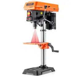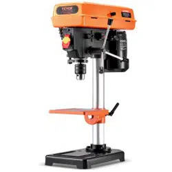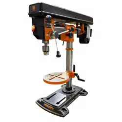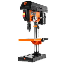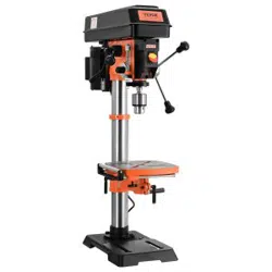

Bench Drill Press
Instruction Manual
Model:DP12VL
Technical Support and E-Warranty Certificate
www.vevor.com/support
We continue to be committed to provide you tools with competitive price.
"Save Half", "Half Price" or any other similar expressions used by us only represents an
estimate of savings you might benefit from buying certain tools with us compared to the major
top brands and doses not necessarily mean to cover all categories of tools offered by us.
You are kindly reminded to verify carefully when you are placing an order with us if you are
actually saving half in comparison with the top major brands.

1
IMPORTANT:
Your new tool has been engineered and manufactured to highest standards for dependability,ease
of operation, and operator safety. When properly cared for, this product will supply you years of rugged,
trouble-free performance. Pay close attention to the rules for safe operation, warnings, and cautions. If you use
your tool properly and for its intended purpose, you will enjoy years of safe, reliable service.
NEED HELP? CONTACT US!
Have product questions? Need technical support? Please feel free to contact us:
This is the original instruction, please read this manual carefully before use.VEVOR reserves the right to
interpret the instructions.The appearance of the product shall be subject tothe product you received.
Please forgive us that we won't inform you again if there is any technology or software updates on our
product.
Bench Drill Press
Model:DP12VL

2
CONTENTS
3 EMOCLEW
Introduction ............................................................................................................. 3
Specifications ........................................................................................................... 3
4 YTEFAS
General Safety Rules ................................................................................................ 4
Specific Safety Rules for the Drill Press ................................................................ 6
Electrical Information ............................................................................................... 8
Know Your Drill Press .............................................................................................. 9
BEFORE OPERATING 01
Assembly & Adjustments ...................................................................................... 10
OPERATION & MAINTENANCE 91
Operation ................................................................................................................ 19
Maintenance ............................................................................................................ 23
Troubleshooting Guide ........................................................................................... 24
Exploded View & Parts List ................................................................................... 26

3
SPECIFICATIONS
INTRODUCTION
Thanks for purchasing the Drill Press. We know you are excited to put your tool to work, but first, please
take a moment to read through the manual. Safe operation of this tool requires that you read and understand this
operator’s manual and all the labels affixed to the tool. This manual provides information regarding potential safety
concerns, as well as helpful assembly and operating instructions for your tool.
NOTE: The following safety information is not meant to cover all possible conditions and situations that may occur.
Keep this manual available to all users during the entire life of the tool and review it frequently to maximize
safety for both yourself and others.
Indicates danger, warning, or caution. The safety symbols and the explanations with them deserve your
careful attention and understanding. Always follow the safety precautions to reduce the risk of fire, electric shock
or personal injury. However, please note that these instructions and warnings are not substitutes for proper ac -
cident prevention measures.
Motor 120V, 60 Hz, 5A
Speed 580-3200 RPM (no load)
Chuck Capacity
Stroke 3-1/8"(80mm)
Swin
1/32" - 5/8"(Φ16mm))
g 12"(300mm)
Capacity (Chuck to Base) 23"(595mm)
Chuck Taper JT3
Spindle Taper MT2
Table Bevel 0 to 45
° left and right
Laser
Class III, transformer powered,
650 nm, <2.5 mW
Product Weight 78.5 lbs(N.W.: 35.75kg)
Product Dimensions 21-1/4 in. x 13-1/2 in. x 37 -1/2 in.
(340*540*950mm)

4
GENERAL SAFETY RULES
WORK AREA SAFETY
1. Keep work area clean and well lit. Cluttered or dark
areas invite accidents.
2. Do not operate power tools in explosive atmo -
spheres, such as in the presence of flammable liquids,
gases or dust. Power tools create sparks which may ig -
nite the dust or fumes.
3. Keep children and bystanders away while operating
a power tool. Distractions can cause you to lose control.
ELECTRICAL SAFETY
1. Power tool plugs must match the outlet. Never mod -
ify the plug in any way. Do not use any adapter plugs
with earthed (grounded) power tools. Unmodified plugs
and matching outlets will reduce risk of electric shock.
2. Avoid body contact with earthed or grounded surfac -
es such as pipes, radiators, ranges and refrigerators.
There is an increased risk of electric shock if your body
is earthed or grounded.
3. Do not expose power tools to rain or wet conditions.
Water entering a power tool will increase the risk of elec -
tric shock.
4. Do not abuse the cord. Never use the cord for car -
rying, pulling or unplugging the power tool. Keep cord
away from heat, oil, sharp edges or moving parts.
Damaged or entangled cords increase the risk of electric
shock.
5. When operating a power tool outdoors, use an ex -
tension cord suitable for outdoor use. Use of a cord
suitable for outdoor use reduces the risk
of electric
shock.
6. If operating a power tool in a damp location is un -
avoidable, use a ground fault circuit interrupter (GFCI)
protected supply. Use of a GFCI reduces the risk of elec-
tric shock.
PERSONAL SAFETY
1. Stay alert, watch what you are doing and use com -
mon sense when operating a power tool. Do not use a
power tool while you are tired or under the influence
of drugs, alcohol or medication. A moment of inatten-
tion while operating power tools may result in serious
personal injury.
2. Use personal protective equipment. Always wear
eye protection. Protective equipment such as a respira-
tory mask, non-skid safety shoes and hearing protection
used for appropriate conditions will reduce the risk of
personal injury.
3. Prevent unintentional starting. Ensure the switch is
in the off-position before connecting to power source
and/or battery pack, picking up or carrying the tool.
Carrying power tools with your finger on the switch or
energizing power tools that have the switch on invites
accidents.
4. Remove any adjusting key or wrench before turning
the power tool on. A wrench or a key left attached to a
rotating part of the power tool may result in personal
injury.
5. Do not overreach. Keep proper footing and
balance
at all times. This enables better control of the power
tool in unexpected situations.
6. Dress properly. Do not wear loose clothing or jew -
elry. Keep your hair and clothing away from moving
parts. Loose clothes, jewelry or long hair can be caught
in moving parts.
Safety is a combination of common sense, staying alert and knowing how your item works. The term “power tool”
in the warnings refers to your mains-operated (corded) power tool or battery-operated (cordless) power tool.
SAVE THESE SAFETY INSTRUCTIONS.
WARNING! Read all safety warnings and all instructions. Failure to follow the warnings and instructions may
result in electric shock, fire and/or serious injury.

5
GENERAL SAFETY RULES
7. If devices are provided for the connection of dust
extraction and collection facilities, ensure these are
connected and properly used. Use of dust collection
can reduce dust-related hazards.
POWER TOOL USE AND CARE
1. Do not force the power tool. Use the correct power
tool for your application. The correct power tool will
do the job better and safer at the rate for which it was
designed.
2. Do not use the power tool if the switch does not turn
it on and off. Any power tool that cannot be controlled
with the switch is dangerous and must be repaired.
3. Disconnect the plug from the power source and/or
the battery pack from the power tool before making
any adjustments, changing accessories, or storing
power tools. Such preventive safety measures reduce
the risk of starting the power tool accidentally.
4. Store idle power tools out of the reach of children
and do not allow persons unfamiliar with the power
tool or these instructions to operate the power tool.
Power tools are dangerous in the hands of untrained us-
ers.
5. Maintain power tools. Check for misalignment or
binding of moving parts, breakage of parts and any
other condition that may affect the power tool’s opera -
tion. If damaged, have the power tool repaired before
use. Many accidents are caused by poorly maintained
power tools.
6. Keep cutting tools sharp and clean. Properly main-
tained cutting
tools with sharp cutting edges are less
likely to bind and are easier to control.
7. Use the power tool, accessories and tool bits, etc.
in accordance with these instructions, taking into ac -
count the working conditions and the work to be per -
formed. Use of the power tool for operations different
from those intended could result in a hazardous situa-
tion.
8. Use clamps to secure your workpiece to a stable
surface. Holding a workpiece by hand or using your
body to support it may lead to loss of control.
9. KEEP GUARDS IN PLACE and in working order.
SERVICE
1. Have your power tool serviced by a qualified repair
person using only identical replacement parts. This
will ensure that the safety of the power tool is main -
tained.
CALIFORNIA PROPOSITION 65 WARNING
Some dust created by power sanding, sawing, grinding,
drilling, and other construction activities may contain
chemicals, including lead, known to the State of Califor-
nia to cause cancer, birth defects, or other reproductive
harm. Wash hands after handling. Some examples of
these chemicals are:
• Lead from lead-based paints.
• Crystalline silica from bricks, cement, and other
masonry products.
• Arsenic and chromium from chemically treated
lumber.
Your risk from these exposures varies depending on
how often you do this type of work. To reduce your ex -
posure to these chemicals, work in a well-ventilated area
with approved safety equipment such as dust masks
specially designed to filter out microscopic particles.
Safety
is a combination of common sense, staying alert and knowing how your item works. The term “power tool”
in the warnings refers to your mains-operated (corded) power tool or battery-operated (cordless) power tool.
SAVE THESE SAFETY INSTRUCTIONS.
WARNING! Read all safety warnings and all instructions. Failure to follow the warnings and instructions may
result in electric shock, fire and/or serious injury.

1. TOOL PURPOSE. This drill press is designed to drill through metal and wood. Drilling through other materials
could result in fire, injury, or damage to the workpiece. Using the machine for any other purpose for which it is not
designed may result in serious injuries, machine damage and voiding of the warranty.
2. MACHINE MOUNTING. For operation safety, the drill press must be securely mounted onto a flat and stable
surface or stand.
3. PERSONAL SAFETY.
• Always wear ANSI Z87.1-approved glasses with side shields, hearing protection and a dust mask.
• Do not wear loose clothing or jewelry, as they might get drawn in by the tool. Tie back long hair.
• DO NOT wear gloves while operating this machine.
4. Electric Cords. Keep cords away from heat, oil, sharp edges, and moving parts of the tool. Have an electrician
replace or repair damaged or worn cords immediately.
5. TOOL & ACCESSORIES INSPECTION. Before operation, check the tool and accessories for any damage or
missing parts. Do not use the tool if any part is missing or damaged. Make sure all adjustments are correct and all
connections are tight. Keep all guards in place.
6. DRILLING ACCESSORIES.
• Make sure the drill bit is not damaged before use; only use undamaged drill bits
• Make sure the drill bit is securely locked in the chuck before turning ON.
• Make sure the chuck key is removed from the chuck before turning ON.
• Use clamps or a vise (not included) to secure a workpiece to the table. This will prevent the workpiece from
rotating with the drill bit.
7. Make sure the table lock is tightened before starting the drill press.
8. WORKPIECE REQUIREMENTS.
• Only stand workpieces sturdy enough to withstand the force of the drill bit.
• Inspect the workpiece for imperfections, nails, staples, etc. before drilling. Never drill stock that has questionable
imperfections or embedded foreign objects.
• Do not drill materials without a flat surface unless a suitable support is used (clamp or vise).
9. PREVENTING ACCIDENTAL STARTING. Make sure the power switch is in the OFF position prior to plugging in the
machine. Always make sure the power switch is in the OFF position and the machine is unplugged when doing any
cleaning, assembly, setup operations, or when not in use.
10. Do not operate this tool until it is completely assembled and installed according to the instructions.
11. Remove scrap pieces and other objects from the table before turning ON the drill press.
SPECIFIC RULES FOR THE DRILL PRESS
WARNING: Do not let comfort or familiarity with the product replace strict adherence to product safety
rules. Failure to follow the safety instructions may result in serious personal injury.
6

SPECIFIC RULES FOR THE DRILL PRESS
12. DRILLING THE WORKPIECE.
• Allow spindle to reach full speed before drilling the workpiece.
• Never start the machine with the drill bit pressed against the workpiece.
• Adjust the table or depth stop to avoid drilling into the table.
• Set the drill press to the speed that is appropriate for the material being drilled.
13. Do not touch moving pieces. Keep hands away from the drill bit during operation. If cleaning is necessary, turn
off the machine and use a brush to remove sawdust and chips instead of your hands.
14. Never perform layout, assembly or set-up work on the table while the machine is ON.
15. After turning off the drill press, wait until the spindle comes to a complete stop before touching the workpiece.
Always turn the drill OFF before removing scrap from the table.
16. Before leaving the machine, always turn OFF and unplug the machine, remove the drill bit, and clean the table.
Turn Off and unplug the machine before cleaning, making adjustments or changing drill bits. Accidental start-ups
may occur if the tool is plugged in during an accessory change or adjustment.
17. CLEANING. Never use solvents to clean plastic parts. Solvents could dissolve or otherwise damage the material.
Use only a soft damp cloth to clean plastic parts.
18. REPLACEMENTS. Should any component of your drill press be missing/damaged or fail in any way, shut OFF
the switch and remove the plug from power supply outlet. Replace the missing, damaged, or failed parts using
only identical replacement parts before resuming operation.
CALIFORNIA PROPOSITION 65 WARNING
Some dust created by power sanding, sawing, grinding, drilling, and other construction activities may contain
chemicals, including lead, known to the State of California to cause cancer, birth defects, or other reproductive
harm. Wash hands after handling. Some examples of these chemicals are:
• Lead from lead-based paints.
• Crystalline silica from bricks, cement, and other masonry products.
• Arsenic and chromium from chemically treated lumber.
Your risk from these exposures varies depending on how often you do this type of work. To reduce your exposure
to these chemicals, work in a well-ventilated area with approved safety equipment such as dust masks specially
designed to filter out microscopic particles.
These safety instructions can’t possibly warn of every scenario that may arise with this tool,
so always make sure to stay alert and use common sense during operation.
7
8
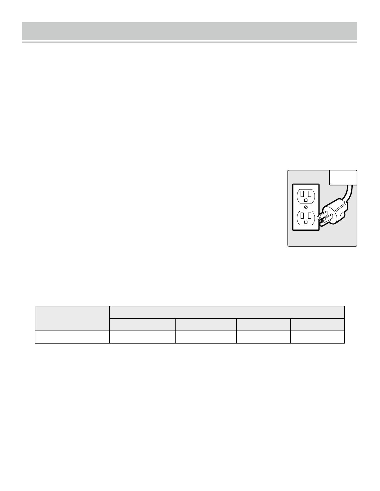
ELECTRICAL INFORMATION
AMPERAGE
REQUIRED GAUGE FOR EXTENSION CORDS
25 ft. 50 ft. 100 ft. 150 ft.
5A 18 gauge 16 gauge 16 gauge 14 gauge
3.
Check
with a licensed electrician or service personnel if you do not completely
understand the grounding instructions or whether the tool is properly grounded.
4.
Use only three-wire extension cords
that have three-pronged plugs and outlets
that accept the tool’s plug (INSERT CR). Repair or replace a damaged or worn cord
immediately.
CAUTION!
In all cases, make certain the outlet in question is properly grounded. If
you are not sure, have a licensed electrician check the outlet.
GUIDELINES AND RECOMMENDATIONS FOR EXTENSION CORDS
GROUNDING INSTRUCTIONS
In the event of a malfunction or breakdown
, grounding provides the path of least resistance for an electric
current and reduces the risk of electric shock. This tool is equipped with an electric cord that has an
equipment grounding conductor and a grounding
plug. The plug MUST be plugged into a matching outlet
that is properly installed and grounded in accordance with ALL local codes and ordinances.
1.
Do not modify the plug provided.
If it will not fit the outlet, have the proper outlet installed by a licensed
electrician.
2.
Improper connection
of the equipment grounding conductor can result in electric shock. The conductor
with the green insulation (with or without yellow stripes) is the equipment grounding conductor. If repair or
replacement of the electric cord or plug is necessary, DO NOT connect the equipment grounding conductor
to a live terminal.
1.
Examine extension cord before use.
Make sure your extension cord is properly wired and in good condition.
Always replace a damaged extension cord or have it repaired by a qualified person before using it.
2.
Do not abuse extension cord.
Do not pull on cord to disconnect from receptacle; always disconnect by pulling
on plug. Disconnect the extension cord from the receptacle before disconnecting the product from the extension
cord. Protect your extension cords from sharp objects, excessive heat and damp/wet areas.
3.
Use a separate electrical circuit for your tool.
This circuit must not be less than a 12-gauge wire and should
be protected with a 15A time-delayed fuse. Before connecting the motor to the power line, make sure the switch is in
the OFF position and the electric current is rated the same as the current stamped on the motor nameplate. Running
at a lower voltage will damage the motor.
When using an extension cord, be sure to use one heavy enough to carry the current your product will draw. An un -
dersized cord will cause a drop in line voltage resulting in loss of power and overheating. The table below shows the
correct size to be used according to cord length and ampere rating. When in doubt, use a heavier cord. The smaller
the gauge number, the heavier the cord.
Fig. 1
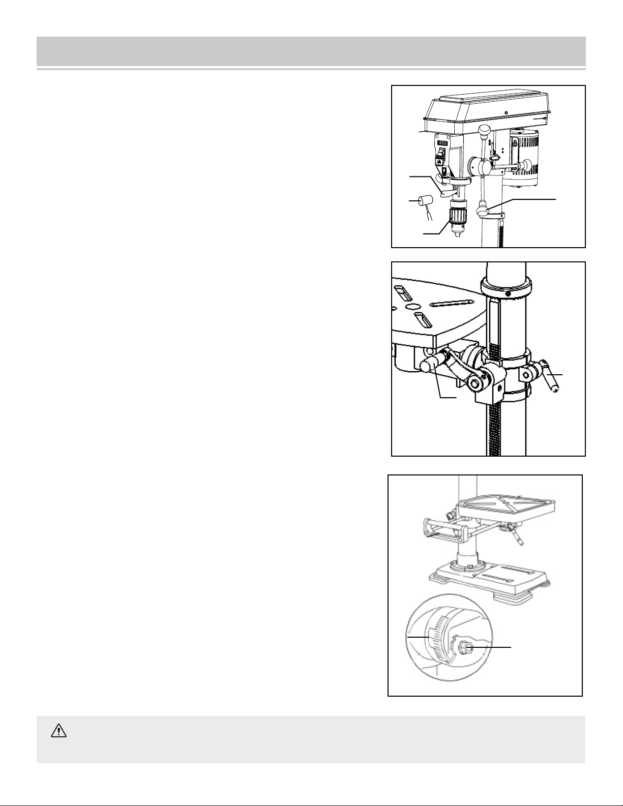
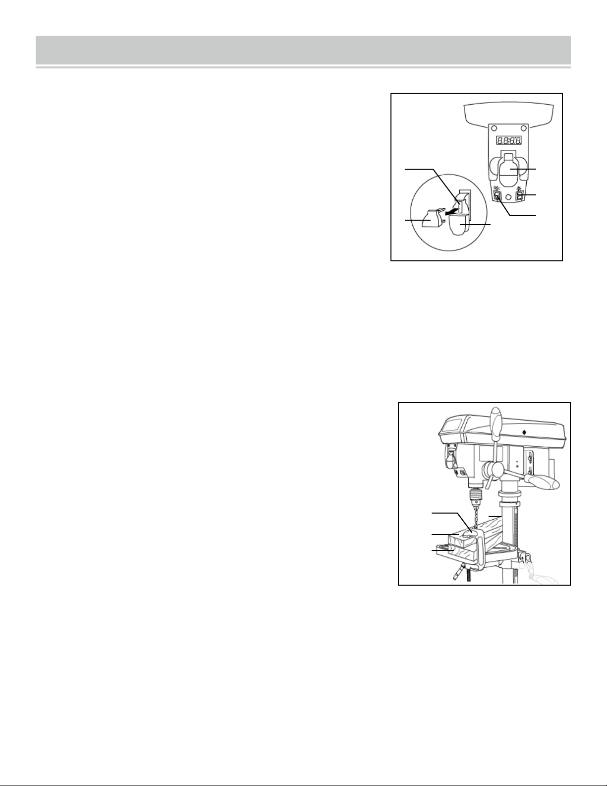
KNOW YOUR DRILL PRESS
TOOL PURPOSE
Drill presses are mainly used to drill clean, precise cylindrical holes into workpieces or enlarge existing holes. You
may also find other uses for your drill press such as reaming, countersinking, counterboring, etc. Refer to
the diagram below and on page 10 to become familiarized with the parts and controls of your drill press.
Column
Rack
Crank Handle
Column Support
Base
Table Lock Handle
Laser ON / OFF Switch
LED Worklight Switch
Support Lock Handle
Speed Control Handle
Chuck Key Storage
1.
2.
3.
4.
5.
6.
7.
8.
9.
10.
11.
12.
13.
14.
15.
16.
17.
18.
19.
Extension Wing
20.
Digital Speed Readout
ON / OFF Switch
Depth Scale
Chuck
Table
Feed Handles
Housing Cover Screw
Housing Cover
1
2
3
4
5
6
7
8
9
10
11
12
13
14
15
16
17
20
18
19
9
Fig. 2
10
CLEANING THE WORK TABLE SURFACE
Your drill press comes protected with a layer of anti-rust coating on its exposed (non-painted) metal surfaces.
Clean the rust-protected surfaces using a soft cloth, moistened with kerosene. Do not use gasoline, or
cellulose-based solvents such as paint thinner or lacquer thinner, as these will damage the painted surfaces.
After cleaning, apply a light coat of good-quality paste wax to the table and column to prevent rust. Wipe all
parts thoroughly with a clean, dry cloth.
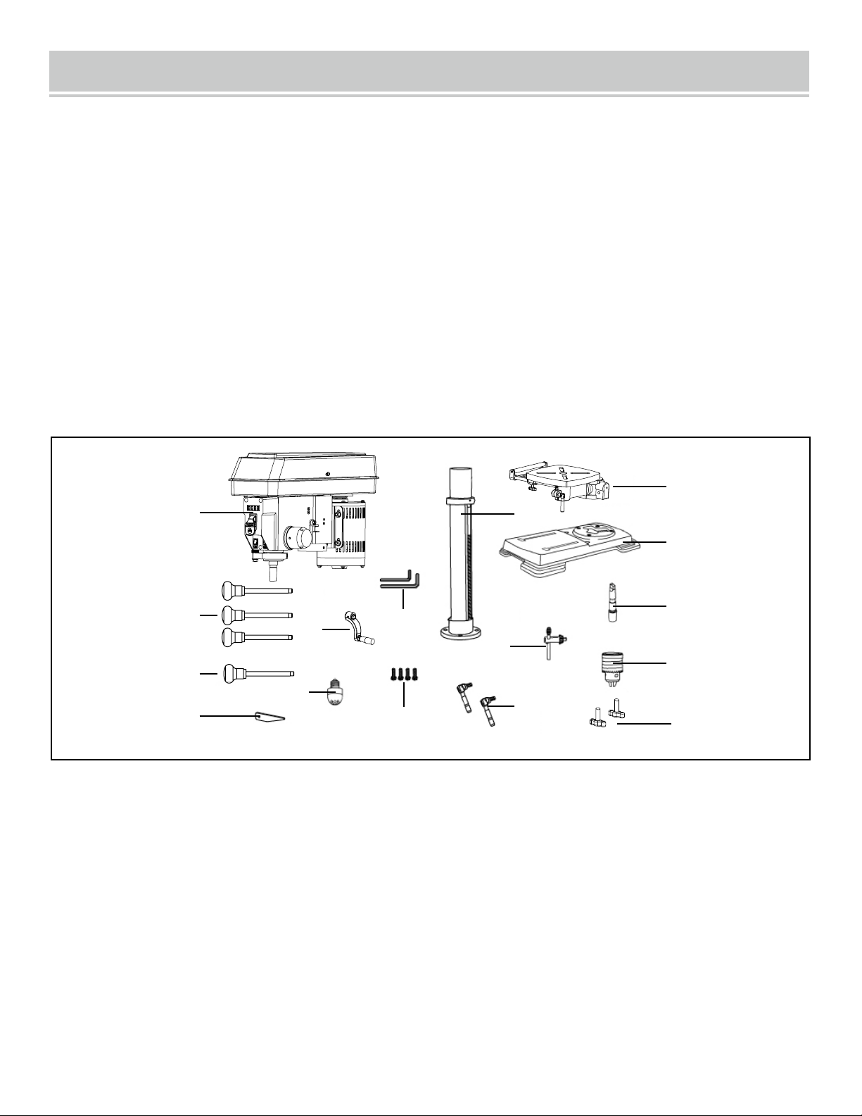
ASSEMBLY & ADJUSTMENTS
UNPACKING
With the help of a friend or trustworthy foe, carefully remove the drill press from the packaging. Make
sure to take out all contents and accessories. Do not discard the packaging until the drill press is
completely assembled.
Before using the drill press, you must assemble the unit using the instructions in this section. Check
your packing list against the diagram below.
1 2
3
4
5
6
8
10
11
12
13
15
9
13
7.
Speed Handle (1)
8.
Chuck Key(1)
9.
Wedge(1)
10.
Table Lock Handles (2)
11.
Hex Head Bolts (4)
12.
Table Crank Handle(1)
1.
Head / Motor Assembly
(1)
2.
Column Assembly
(1)
3.
Table(1)
4.
Base(1)
5.
Chuck Arbor(1)
6.
13.
Hex Wrenches (3mm & 4mm)
14.
Feed Handles (3)
15.
LED Bulb(1)
16.
Wing Knobs (2)
Chuck(1)
14
7
16
The column assembly (column, column support, rack, rack collar, and table support bracket) must be
attached to the base. The table and table support handles must be attached to the table support bracket. The
head must be attached to the column.
Tools needed for assembly (not included):
• Adjustable wrench
• Hammer and block of wood, OR dead blow hammer, OR rubber mallet
• Screwdriver
11
ASSEMBLY & ADJUSTMENTS
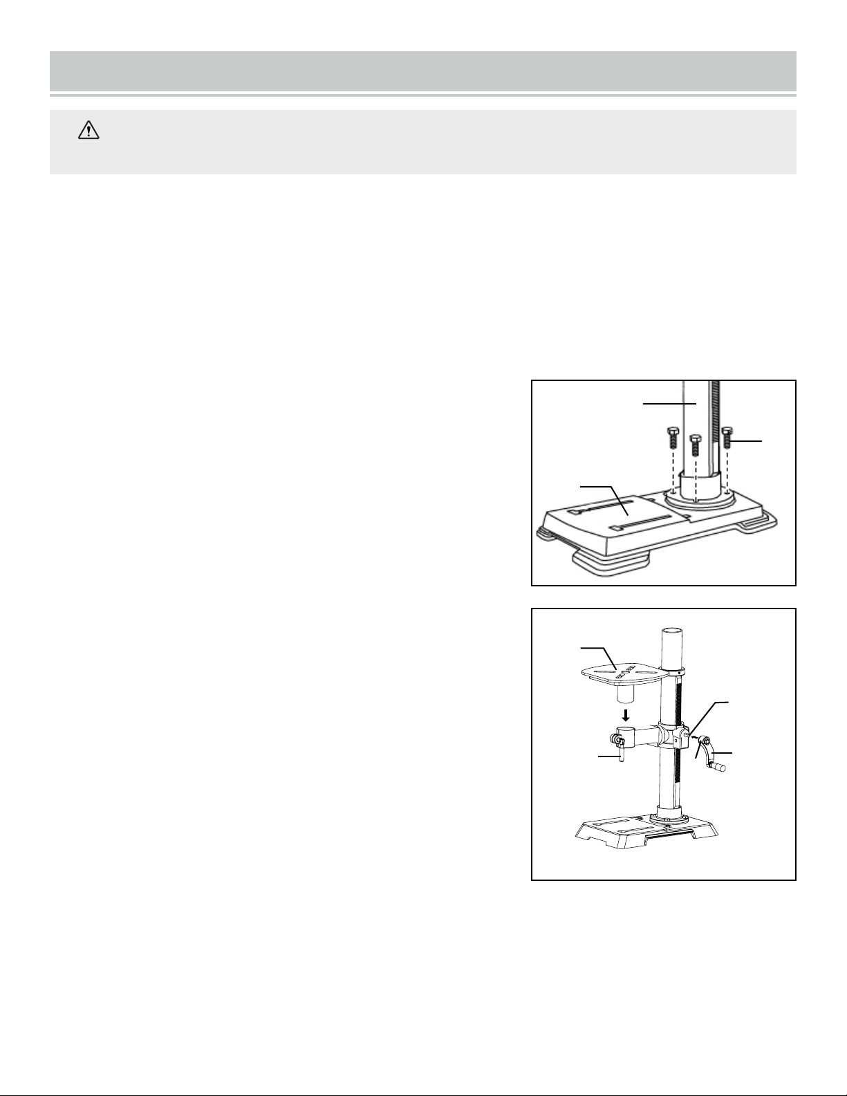
ATTACHING COLUMN TO BASE (FIG. 3)
1. Place the column assembly (Fig. 3 - 1) on the base (Fig. 3 - 2),
aligning the column support holes to the base holes.
2. Install a hex head bolt (Fig. 3 - 3) in each column support hole
and tighten bolts using the adjustable wrench (not included).
TABLE TO TABLE SUPPORT BRACKET (FIG. 4)
1. Place the crank handle (Fig 4 - 1) onto the shaft (Fig 4 - 2) of
the table bracket so the flat of the shaft is under the set screw
(Fig. 4 - 3). Tighten the set screw.
2. Thread the table lock handle (Fig. 4 - 4) into the front of the
table support bracket.
3. Thread the table support lock handle into the rear of the table
support bracket (not shown).
4. Position the table (Fig. 4 - 5) in the same direction as the base.
Install the table and tighten the table lock handle
(Fig. 4 - 4) and support lock handle.
Fig. 3
Fig. 4
1
2
3
1
3
4
5
WARNING: If any part is missing or damaged, do not plug the drill press in until the missing or
damaged part is repaired or replaced.
2
ASSEMBLY & ADJUSTMENTS
DRILL PRESS HEAD TO COLUMN (FIG. 5)
1. Carefully lift the drill press head assembly (Fig. 5 - 1) and
position it over the column (Fig. 5 - 2).
2. Place the mounting opening (Fig. 5 - 3) on the drill press
head over the top of the column. Make sure the drill press
head is seated properly on the column.
3. Align the direction of the drill press head with the direction
of the base and the table.
4. Tighten the set screw (Fig. 5 - 4) using the included hex
wrench.
FEED HANDLES (FIG. 6)
1. Insert the three feed handles (Fig. 6 - 1) into the threaded
openings on the feed hub (Fig. 6 - 2).
2. Manually tighten the handles into the openings. Use an
adjustable wrench (not included) to grip the flats on the
handles and fully tighten them.
NOTE: When using the drill press, one or two of the feed
handles may be removed if an unusually-shaped workpiece
interferes with the handle rotation.
SPEED HANDLE (FIG. 7)
1. Insert the speed handle (Fig. 7 - 1) into the threaded opening
on the speed hub (Fig. 7 - 2).
2. Manually tighten the handle into the openings. Use an
adjustable wrench (not included) to grip the flats on the
handles and fully tighten them.
12
Fig. 5
Fig. 6
Fig. 7
1
2
34
1
1
2
WARNING: The drill press head is heavy. To avoid
injury, two people should lift it into position.
2
MOUNTING THE DRILL PRESS (FIG. 8)
The drill press must be securely fastened through the mounting
holes (Fig. 8 - 1) to a stand or workbench with heavy-duty
fasteners (not included). This will prevent the drill press from
tipping over, sliding, or walking during operation.
IMPORTANT: If the stand or workbench has a tendency to move
during operation, fasten the workbench securely to the floor.
LED BULB
An LED bulb has been assembled in the socket of the head.
ASSEMBLY & ADJUSTMENTS
13
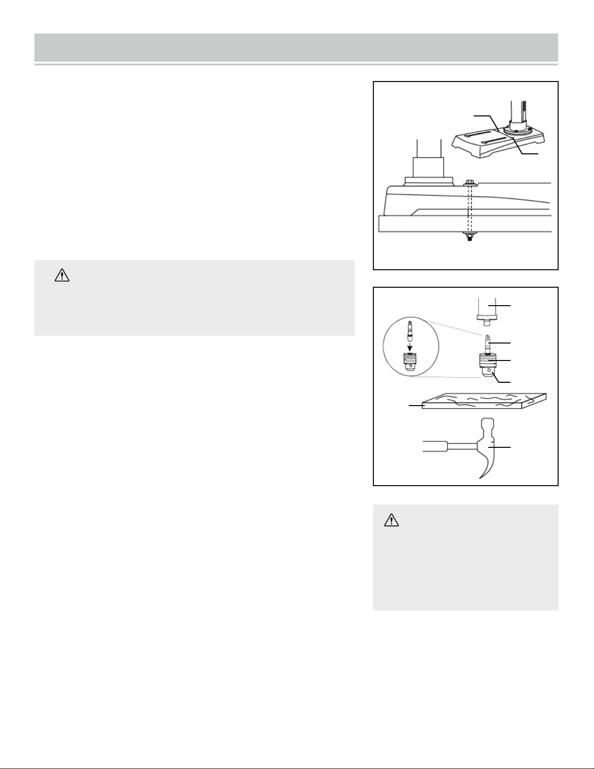
INSTALL THE CHUCK (FIG. 9)
1. Inspect and clean the taper hole in the chuck
(Fig. 9 - 1) and the spindle (Fig. 9 - 2). Remove all grease, coatings,
and particles from the chuck and spindle surfaces
with a clean cloth.
2. Open the chuck jaws (Fig. 9 - 3) by manually turning the chuck
barrel clockwise. Make sure the jaws are completely recessed
inside the chuck.
3. Insert the chuck arbor (Fig. 9 - 4) into the opening at the top of
the chuck.
4. Insert the arbor into the spindle. Rotate it until the tang of the
arbor (the flats on the end) is aligned with the slot in the spindle,
and the chuck and arbor can be pushed upwards. Seat the chuck by
placing a block of wood (Fig. 9 - 5, not included) below the chuck
and firmly tapping the wood once with a hammer. Alternatively,
firmly tap the chuck once with a rubber mallet or dead-blow
hammer (not included).
Fig. 8
Fig. 9
CAUTION: To avoid damaging
the chuck, make sure the jaws
are completely recessed into
the chuck. Do not use a metal
hammer to drive the chuck onto
the arbor or into the spindle.
1
1
1
2
3
4
5
6
WARNING: To reduce risk of fire, DO NOT use a light
bulb greater than 40 watts. When changing the light bulb,
always check that the power switch is in the OFF position
and the plug is disconnected from its power source.
5. If the chuck or arbor fail to seat properly, they may not be clean enough. Remove them and thoroughly
clean the mating surfaces, then try again. Ensure all dust, debris, and liquids are removed from the surfaces,
and that neither surface is damaged.
ASSEMBLY & ADJUSTMENTS
RAISE OR LOWER THE TABLE (FIG. 11)
1. Loosen the support lock handle (Fig. 11 - 1) and turn the
crank handle (Fig. 11 - 2) until the table is at the desired height.
2. Tighten the support lock handle before drilling.
ROTATE THE TABLE (FIG. 11)
1. Loosen the support lock handle (Fig. 11 - 1) and turn the
table around the column to the desired position.
NOTE: The rack should rotate around the column with the table
support bracket. If the rack binds and does not rotate, slightly
loosen the set screw in the rack collar.
2. Tighten the support lock before drilling.
TILT THE TABLE (FIG. 12A)
1. Loosen the bevel lock bolt (Fig. 12A - 1) by turning it
counterclockwise with an adjustable wrench (not included).
2. Tilt the table to the desired angle, using the bevel scale
(Fig. 12A - 2) as a basic guide.
3. Re-tighten the bevel lock bolt.
ADJUST TABLE TO BE HORIZONTAL (FIG. 12A)
1. Loosen the bevel lock bolt (Fig. 12A - 1).
2. Realign the table to the 0° setting on the bevel scale
(Fig. 12A - 2).
3. Tighten the bevel lock bolt with the adjustment wrench.
Fig. 11
14
REMOVE THE CHUCK (FIG. 10)
1. Turn the feed handles (1) to lower the chuck (2) to the lowest
position.
2. Insert the wedge (3) into the opening in the quill. Gently tap
on the wedge using a rubber mallet (4) (not included). The chuck
and arbor will drop out.
NOTE: To avoid possible damage to the drill or chuck, be prepared
to catch the chuck as it falls.
Fig. 10
1
2
4
1
2
WARNING: To avoid injury, make sure the chuck key is removed from the chuck before starting
3
any drilling operation.
Fig. 12A
1
2
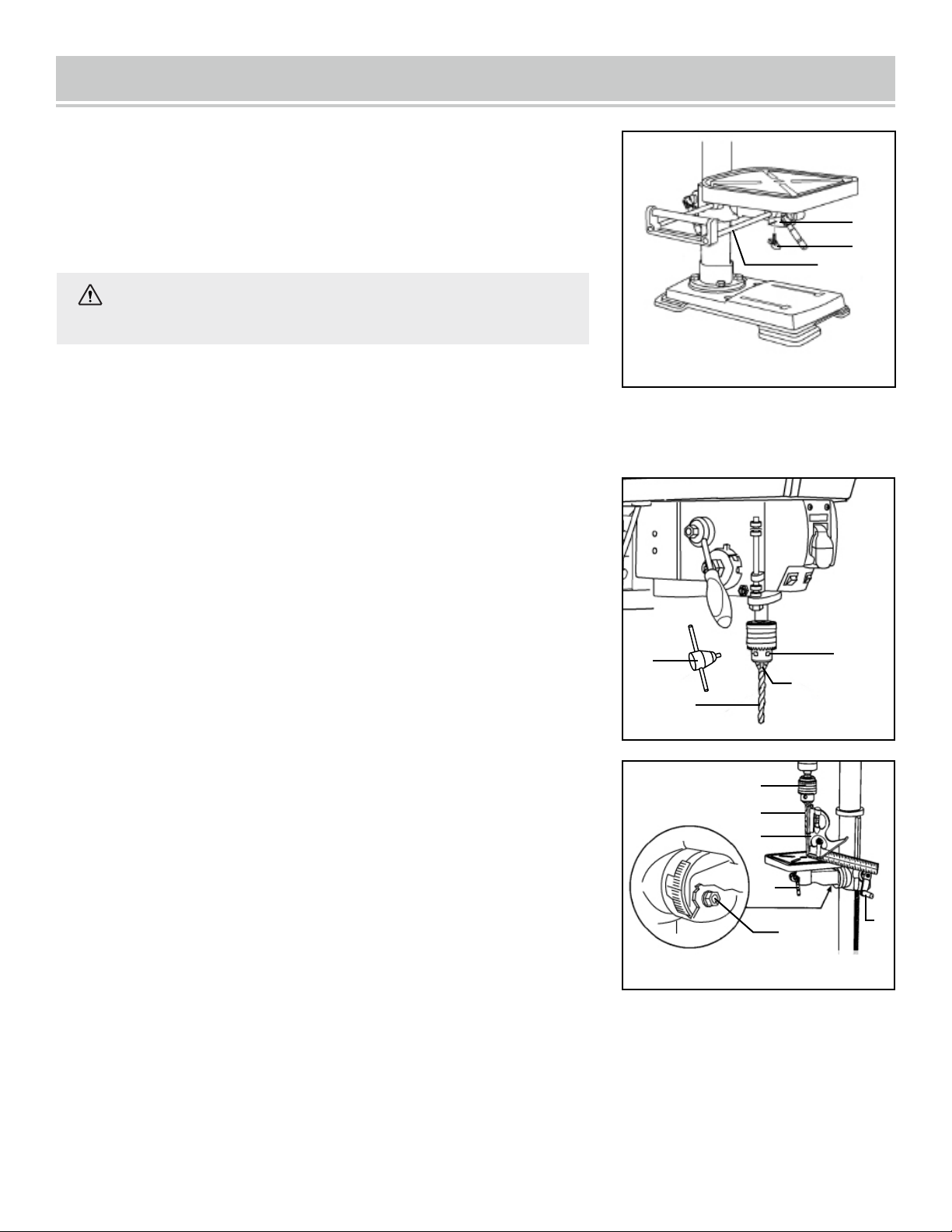
Fig. 13
ASSEMBLY & ADJUSTMENTS
INSTALLING A DRILL BIT (FIG. 13)
1. Place the chuck key (Fig. 13 - 1) into the side keyhole of the chuck
(Fig. 13 - 2), meshing the key with the gear teeth.
2. Turn the chuck key counterclockwise to open the chuck jaws
(Fig. 13 - 3).
3. Insert a drill bit (Fig. 13 - 4) into the chuck far enough to obtain the
maximum grip of the chuck jaws on the bit shank.
4. Center the drill bit in the chuck jaws before the final tightening of
the chuck.
5. Tighten the chuck jaws using the chuck key to ensure that the drill
bit will not slip while drilling. Tighten all three keyholes on the chuck.
6. Remove the chuck key and place it back on the onboard storage.
15
SQUARING TABLE TO THE DRILL BIT (FIG. 14)
1. Insert a 3" long drill bit (Fig. 14 - 1) into the chuck (Fig. 14 - 2) and
tighten the jaws with the chuck key.
2. Raise the table with the crank handle (Fig. 14 - 3). Lock the table
(Fig. 14 - 4) approximately 1" below the drill bit.
3. Place a combination square (Fig. 15 - 5) (not included) on the
table as shown, placing the long straight edge of the combination
square against the drill bit. Make sure the drill bit is parallel / aligned
exactly to the straight edge of the square.
Fig. 14
1
2
3
4
1
2
3
4
5
6
Fig. 12B
INSTALL THE TABLE EXTENSION (FIG. 12B)
1. Insert the two rods (Fig. 12B - 1) of the table extension into the
two channels (Fig. 12B - 2) at the side of the table.
2. Place a wing knob (Fig. 12B - 3) in the opening on the bottom of
each channel and tighten to secure the extension to the table.
1
2
3
WARNING:
To avoid injury, make sure the chuck key is
removed from the chuck before starting any drilling operation.
4. If an adjustment is needed, loosen the bevel lock bolt (Fig. 14 - 6) with a wrench.
5. Tilt the table slightly, until the combination straight edge is aligned perfectly with the drill bit.
6. Tighten the bevel lock when square.
ASSEMBLY & ADJUSTMENTS
ADJUSTING THE LASER (FIG. 15 & 16)
1. Place a workpiece on the table.
2. Turn the laser switch (Fig. 15 - 1) to the ON position.
3. Lower the drill bit to meet the workpiece (Fig. 16 - 2). The two laser
lines should cross where the drill meets the workpiece.
4. If the laser needs to be adjusted:
a. Using the included 3 mm hex key, turn the laser adjustment set
screws (Fig. 15 - 3) counterclockwise. There is one of each side
of the head.
b. Rotate the laser light housing (Fig. 15 - 4) until the two laser
lines intersect where the drill meets the workpiece.
5. Re-tighten the adjustment set screws (Fig. 15 - 3).
Fig. 15
Fig. 16
16
1
3
4
4
2
WARNING: Do not stare directly at the laser beam. Observe all safety rules.
• Never aim the beam at a person or an object other than the workpiece.
• Always make sure the laser beam is aimed at a workpiece that does not have reflective surfaces, as
the laser beam could reflect into your eyes or the eyes of others.
ASSEMBLY & ADJUSTMENTS
17
SPINDLE RETURN SPRING (FIG. 17)
The spindle is equipped with an auto-return mechanism. The main
components are a spring and a notched housing. The spring was properly
adjusted at the factory and should not be readjusted unless absolutely
necessary.
1. Unplug the drill press.
2. Place a screwdriver into the loop (Fig. 17 - 1) to hold the spring in
place.
3. Loosen the two housing nuts (Fig. 17 - 2) approximately 1/4" (6 mm).
Do not remove the nuts from the threaded shaft. Do not allow the spring
or spring housing to slip out of control.
4. While firmly holding the spring housing (Fig. 17 - 3), carefully pull
spring housing out until it clears the raised stop (Fig. 17 - 4).
5. Turn the housing so that the next notch (Fig. 17 - 5) is engaged with
the raised stop (Fig. 17 - 4).
• To increase the spindle return tension, turn the spring housing
counter-clockwise.
• To decrease the tension, turn the spring housing clockwise.
6. Tighten the two housing nuts. Do not overtighten the two nuts. If
the nuts are tightened too much, the movement of the spindle and feed
handles will become sluggish.
Fig. 17
ANGULAR “PLAY” OF THE SPINDLE (FIG. 18)
Move the spindle to the lowest downward position and hold in place. Try
to make the spindle revolve around its axis while also moving it with a
side motion. If there is too much “play”, proceed as follows:
1. Loosen the outer nut (Fig. 18 - 1) about 1/8 inch.
2. Without obstructing the upward and downward motion of the spindle,
turn the screw (Fig. 18 - 2) clockwise to eliminate the “play.”
NOTE: A little bit of “play” is normal.
3. Tighten the lock nut (Fig. 18 - 1).
Fig. 18
1
2
3
4
5
2
1
NOTE: Adjustments for
the correct function of
your drill press return
spring have been done by
the factory. Please do not
modify them. However,
prolonged use of the drill
press may make some
readjustments necessary.
ASSEMBLY & ADJUSTMENTS
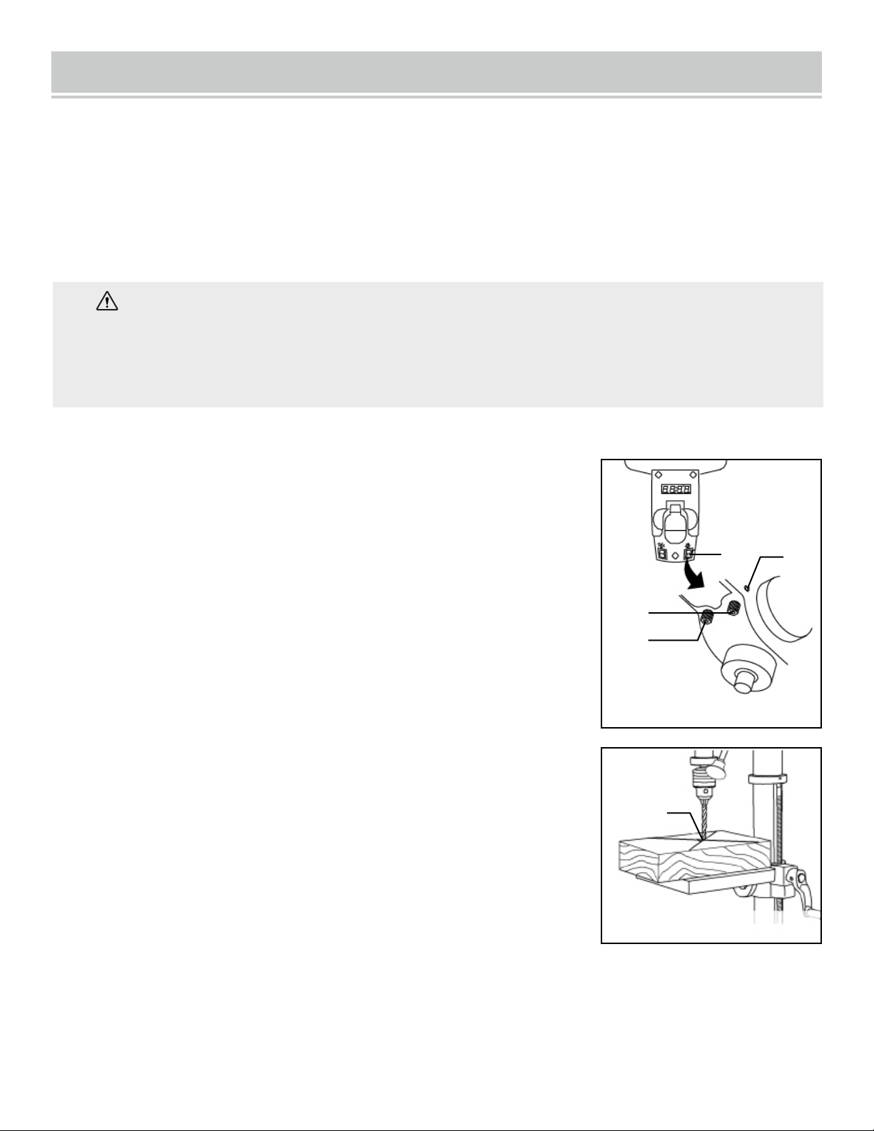
DRILL PRESS ON / OFF SWITCH (FIG. 19)
1. To turn the drill press ON, insert the yellow safety key (Fig. 19 - 1)
into the switch housing (Fig. 19 - 2). As a safety feature, the switch
cannot be turned ON without the safety key.
2. Flip the switch upward to the ON position.
3. To turn the drill press OFF, flip the switch downward.
4. To lock the switch in the OFF position, remove the safety key
(Fig. 19 - 1) from the switch. Store the safety key in a safe place away
from the reach of children.
Fig. 19
LIGHT & LASER LINE ON/OFF SWITCHES (FIG. 19)
The light switch (Fig. 19 - 3) is located on the lamp cover.
The laser switch (Fig. 19 - 4) is located below the ON/OFF switch on
the right.
Fig. 20
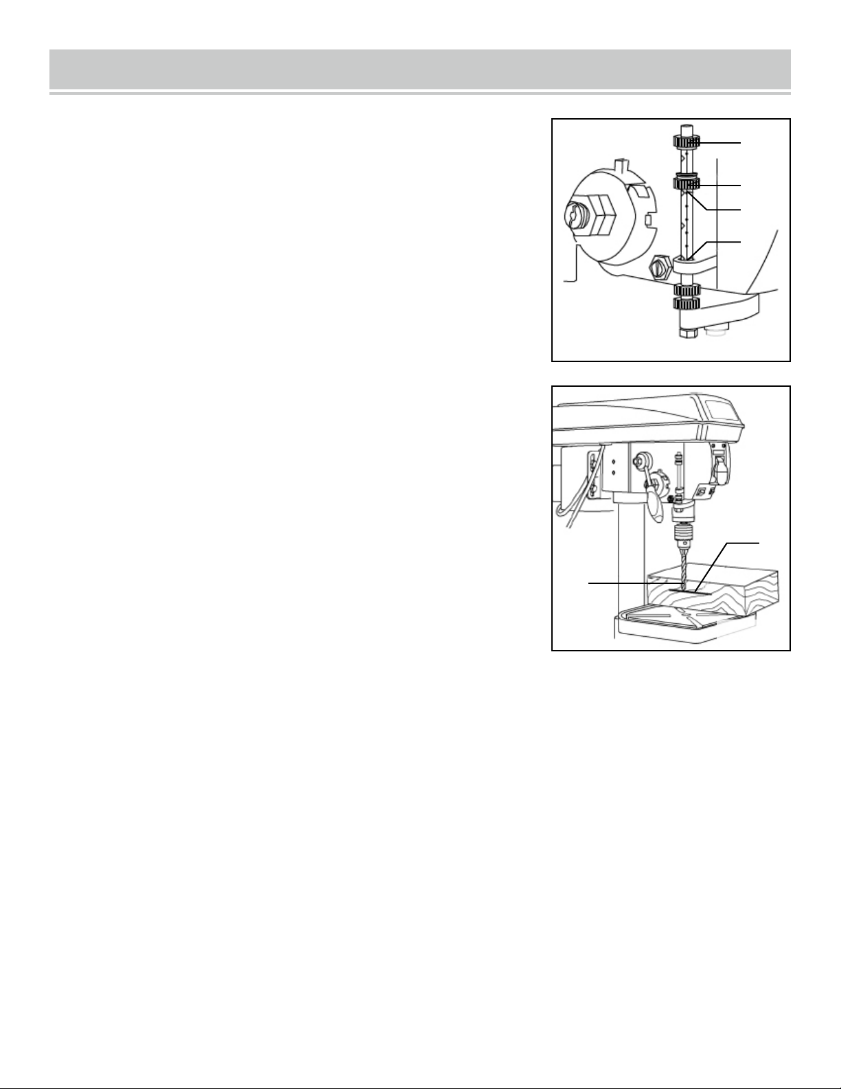
POSITION THE TABLE AND WORKPIECE (FIG. 20)
Always place a piece of backup material (Fig. 20 - 1) (wood, plywood,
etc.) on the table underneath the workpiece (Fig. 20 - 2). This will
prevent splintering on the underside of the workpiece as the drill bit
breaks through. To keep the material from spinning out of control, it
must contact the left side (Fig. 20 - 3) of the column as illustrated, or
be clamped (Fig. 20 - 4; not included) to the table.
NOTE: For small workpieces that cannot be clamped to the table, use a
drill press vise (not included). The vise must be clamped or bolted to
the table to avoid injury.
1
2
3
3
4
5
1
2
3
4
18
OPERATION
GENERAL DRILLING GUIDELINES - DRILLING A HOLE
1. Mark where you want to drill in workpiece by using a center punch or a sharp nail or turn ON the laser to
mark your drilling point.
2. Before turning the drill press ON, turn the feed handles to bring the drill bit down. Line the drill bit tip up
with the mark. Clamp the workpiece in place.
3. Turn ON the drill press and pull down on the feed handles with the appropriate force needed to allow the
drill bit to drill the material.
NOTE: Feeding too slowly might cause the drill bit to turn in the chuck. Feeding too rapidly
might stop the motor, cause the belt to slip, force the workpiece loose, or break the drill bit. Practice with
scrap material to get the feel of the machine before attempting to do any drilling operation.
WARNING: To prevent the workpiece and the backup material from slipping from your hand
while drilling, position the workpiece and backup material to the left side of the column. If the
workpiece and the backup material are not long enough to reach the column, clamp the workpiece
and backup material to the table. Failure to do this could result in personal injury.
Fig. 21A
ADJUST THE DRILLING DEPTH (FIG. 21A)
The depth gauge controls the maximum distance the drill bit will
move up or down.
TO STOP THE DRILL BIT AT A PRE-MEASURED DEPTH:
1. Rotate the lower depth scale knob (Fig. 21A - 2) until the bottom
of the knob is aligned with the desired depth mark
(Fig. 21A - 5) on the gauge scale.
2. Rotate the depth scale lock knob (Fig. 21A - 1) until it meets the
lower depth scale knob (Fig. 21A - 2). The chuck will stop after
travelling downward to the selected distance.
TO ADJUST THE QUILL (RETURN) HEIGHT:
To adjust the upward distance the quill (shaft that moves up and down) can travel:
1. Turn the feed handles until the quill is at the desired height and hold it there.
2. Rotate the lower depth knob (Fig. 21A - 3) until it rests against the bottom of the metal gauge support
(Fig. 21A - 4).
Drilling an unmeasured blind hole (not all the way through the workpiece) to a given depth can be done two
ways: using the depth scale method or workpiece method.
4
5
2
1
3
19
OPERATION
20
DEPTH SCALE METHOD (FIG. 21B)
1. Make sure the 0 (in or mm) mark on the depth gauge rests at the
top edge of the metal support (Fig. 21B - 4) when the quill is fully
retracted.
2. Put the workpiece on the table and raise the table until the tip of the
drill bit just touches the top of the workpiece. Lock the table in place.
3. Determine the drill depth for this workpiece.
4. Rotate the depth knob (Fig. 21B - 2) until it is aligned with the
desired depth mark (Fig. 21B - 3) (for example, 1") on the gauge scale.
5. The chuck will be stopped at the distance selected on the depth
scale.
Fig. 21B
DRILLING SPEEDS
There are a few important factors to keep in mind when determining the best drilling speed:
• Material type
• Hole size
• Drill bit or cutter type
• Quality desired
Smaller drill bits require greater speed than larger drill bits. Softer materials require greater speed than
harder materials. See page 22 for recommended speeds for particular materials.
WORKPIECE METHOD (FIG. 21 & 22)
1. Mark the desired depth (Fig. 22 - 5) of the drill hole on the side of
the workpiece.
2. With the drill press in the OFF position, bring the drill bit
(Fig. 22 - 6) down until the tip is even with the mark.
3. Holding the feed handles at this position, rotate the depth knob
(Fig. 21 - 2) until it meets the metal support.
4. The chuck and the drill bit will now be stopped at the distance
selected on the depth scale.
Fig. 22
1
2
4
3
5
6

OPERATION
21
DRILLING METAL
• Use metal-piercing twist drill bits.
• It is always necessary to lubricate the tip of the drill with oil to prevent overheating of the drill bit.
• All metal workpieces should be clamped down securely. Any tilting, twisting, or shifting causes a rough
drill hole, and increases the potential of drill bit breakage.
• Never hold a metal workpiece with your bare hands. The cutting edge of the drill bit may seize the
workpiece and throw it, causing serious injury. The drill bit will break if the metal piece suddenly hits the
column.
• If the metal is flat, clamp a piece of wood under it to prevent turning. If it cannot be laid flat on the table,
then it should be blocked and clamped.
DRILLING WOOD
• Brad point bits are preferred. Metal piercing twist bits may be used on wood.
• Do not use auger bits. Auger bits turn so rapidly that they can lift the workpiece off of the table and whirl
it around.
• Always protect the drill bit by positioning the table so that the drill bit will enter the center hole when
drilling through the workpiece.
• To prevent splintering, feed the drill bit slowly right as the bit is about to cut through to the backside of
the workpiece.
• To reduce splintering and protect the point of the bit, use scrap wood as a backing or a base block under
the workpiece.
FEEDING THE DRILL BIT
• Pull down on the feed handles with only enough force to allow the drill bit to cut.
• Feeding too rapidly might stall the motor, cause the belt to slip, damage the workpiece, or break the drill
bit.
• Feeding too slowly will cause the drill bit to heat up and burn the workpiece.
Fig. 23
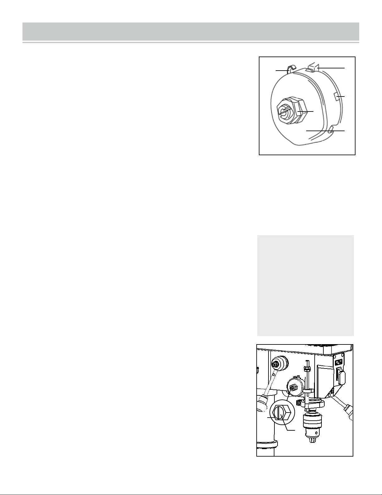
MECHANICAL VARIABLE SPEED (FIG. 23)
This is a mechanical variable speed drill press. To increase or decrease
the speed when operating, raise or lower the speed handle
(Fig. 23 - 1). Use the following table to determine the recommended
speed for the drill size you are using and the type of material you are to
drill. While drilling, check the speed on the digital speed readout
(Fig. 23 - 2) located at the front of the drill press.
1
2
WARNING: Do not change speeds using the variable speed
handle without turning on the machine.
OPERATION
Recommended speed for drill bit size and materials
DRILL BIT SIZE RECOMMENDATIONS
RPM Wood Aluminum, Zinc, Brass Iron, Steel
2000 to 3200 3/8 in. 9.5 mm 7/32 in. 5.6 mm 3/32 in. 2.4 mm
1400 to 2000 5/8 in. 16 mm 11/32 in. 8.75 mm 5/32 in. 4 mm
1000 to 1400 7/8 in. 22 mm 15/32 in. 12 mm 1/4 in. 6.4 mm
800 to 1000 1-1/4 in. 31.75 mm 11/16 in. 17.5 mm 3/8 in. 9.5 mm
580 to 800 1-5/8 in. 41.4 mm 3/4 in. 19 mm 5/8 in. 16 mm
Fig. 24
Belt tension and drill press speed is controlled by automatic
adjustments made to the diameter of the front spindle when the speed
handle is moved.
NOTE: See page 21 for information on the variable speed function of
this drill press.
1. Plug in the drill press and turn it ON. Adjust the speed to the highest
setting, then turn the drill press OFF and unplug it.
2. Open the belt cover (remove the Phillips-head screw from the right
side, then open the lid.
3. Press down on the bottom side of the motor pulley. This will loosen
the belt tension. Work the belt off the pulleys.
WARNING: Do not change
the drive speed when the drill
press is turned off.
REPLACING THE BELT (FIG. 24)
1
2
3
4
WARNING: Disconnect the drill press from the power source
before replacing the belt.
22
4. Place the new belt on the motor pulley, then press down on the bottom side of the pulley as before and
get the belt as close to the motor shaft as possible. Make sure the bottom side of the pulley is pushed fully
downward.
5. Work the belt around the spindle pulley. The belt will not be taut, but will self-seat later.
6. Close and secure the belt cover.
7. Plug in and turn ON the drill press. The belt will self-seat and achieve proper tension on its own.

MAINTENANCE
ROUTINE INSPECTION
Before each use, inspect the general condition of the tool. If any of these following conditions exist, do not
use until parts are replaced.
CHECK FOR:
• Loose hardware or improper mounting,
• Misalignment
• Damaged cord/electrical wiring,
• Cracked or broken parts, and
• Any other condition that may affect its safe operation
CAUTION: Most plastics are susceptible to damage from various types of commercial solvents. Do not
use any solvents or cleaning products that could damage the plastic parts. Some of these include but are
not limited to: gasoline, carbon tetrachloride, chlorinated cleaning solvents, and household detergents
that contain ammonia.
CLEANING & STORAGE
1. After every operation, use a vacuum to remove sawdust or metal shavings from the tool surfaces, motor
housing and work area. Keep the ventilation openings free from dust and debris to prevent the motor from
overheating.
2. Wipe the tool surfaces clean with a soft cloth or brush. Make sure water does not get into the tool.
3. Apply a light coat of paste wax to the column and table to help keep these surfaces clean and rust free.
4. Store the tool in a clean and dry place away from the reach of children.
LUBRICATION
The ball bearings in the spindle and the V-belt pulley assembly are greased and permanently sealed, and
require no lubrication. Pull the spindle down and oil the quill moderately every three months.
Lubricate the table bracket and locking knobs if they become difficult to use.
PRODUCT DISPOSAL
Used power tools should not be disposed of together with household waste. This product contains elec tronic
components that should be recycled. Please take this product to your local recycling facility for responsible
disposal and to minimize its environmental impact.
WARNING:
To avoid accidents, turn OFF and unplug the tool from the electrical outlet before
cleaning, adjusting, or performing any maintenance or lubrication work .
WARNING: Any attempt to repair or replace electrical parts on this tool may be hazardous.
Servicing of the tool must be performed by a qualified technician. When servicing, use only identical
replacement parts. Use of other parts may be hazardous or induce product failure.
23

PROBLEM CAUSE SOLUTION
Noisy operation
or excessive
vibration
1) Incorrect belt tension
2) Dry spindle
3) Loose spindle pulley
4) Loose motor pulley
5) Seized motor pulley
1) Adjust the belt tension.
(See REPLACE THE BELT section)
2) Lubricate the spindle.
3) Tighten the set screws on the side of the
spindle pulley.
4) Tighten the set screws on the side of the
motor pulley.
5) Lubricate motor pulley and motor shaft;
ensure that pulley opens and closes when
machine is ON and speed is adjusted.
The drill bit burns
or smokes
1) Drilling at the incorrect speed
2) The wood chips are not coming out
of the hole
3) Dull drill bit
4) Feeding the workpiece too slowly
5) Not lubricated
1) Change the speed.
2) Retract the drill bit frequently to clear the
chips.
3) Resharpen or replace the drill bit.
4) Feed fast enough to cut the workpiece.
5) Lubricate the drill bit with cutting oil or
motor oil.
Excessive drill
run out or
wobble; drilled
hole is not round
1) Bent drill bit
2) Bit improperly installed in the chuck
3) Worn spindle bearings
4) Lengths of cutting flutes or angles
not appropriate for the hardness of the
wood grain
5) Chuck not properly installed
1) Replace the drill bit.
2) Reinstall the bit.
3) Bearings may need replacement.
4) Resharpen the drill bit correctly or replace
with the appropriate type.
5) Reinstall the chuck.
TROUBLESHOOTING
WARNING: Stop using the tool immediately if any of the following problems occur. Repairs
and replacements should only be performed by an authorized technician.
24

PROBLEM CAUSE SOLUTION
Drill bit binds in
the workpiece
1) The workpiece is pinching the bit
2) Excessive feed pressure
1) Support or clamp the workpiece.
2) Feed more slowly.
Spindle returns
too slowly or too
quickly
Coil spring has improper tension
Adjust the coil spring tension.
See "Spindle Return Spring" on p. 17
Chuck falls off
spindle
Dirt, grease, or oil on the tapered sur -
face on the spindle or in the chuck
Clean the tapered surface of both the chuck and
spindle with a household detergent.
Motor stalls
1) Incorrect fuses or circuit breakers
2) Overloaded circuit
3) Low voltage
1) Replace with correct fuse or circuit breaker
for the circuit.
2) Turn off other machines and retry.
3) Check the power line for the proper
voltage. Use another circuit or have a qualified
electrician upgrade the service.
ASSEMBLY & ADJUSTMENTS
TROUBLESHOOTING
WARNING: Stop using the tool immediately if any of the following problems occur. Repairs
and replacements should only be performed by an authorized technician.
25
26
ASSEMBLY & ADJUSTMENTS
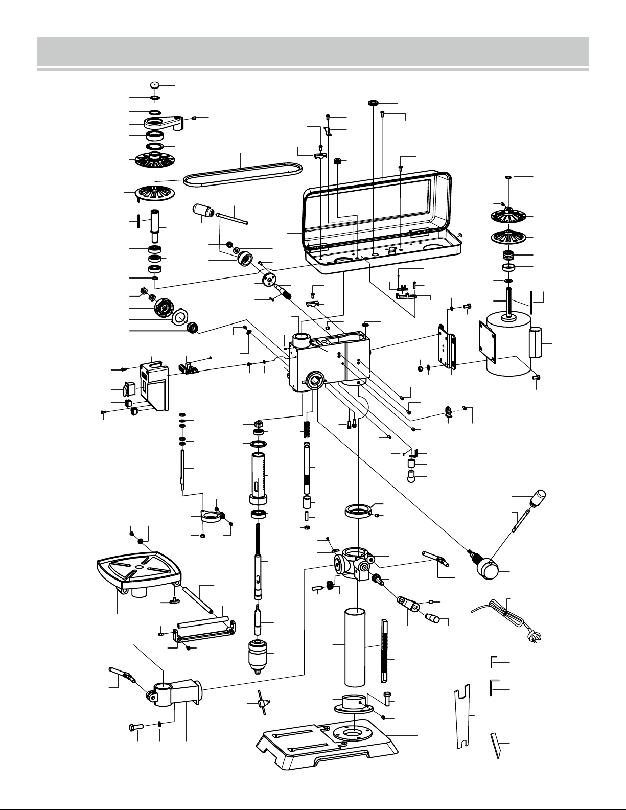
EXPLODED VIEW & PARTS LIST
1
2
3
4
5
7
124
125
34
6
8
9
10
11
12
17
18
19
20
21
22
24
23
77
35
67
25
26
27
28
2930
31
32
33
36
14
81 84
61
85
80
86
52
53
54
59
39
58
60
40 41
42
44
45
46 47
48
49
51 82 50
72
55
56
57
62
63
64
65
129
66
67
31
70
69
68
43
71
73
13
14
15
16
74
3
110
111
112
113
114
115
116
117
120
91
99
118
12141
61
75
77
717876
79
87
88
89
90
38
39
98
99
96
97
100
101
105
106
102
99
83
123
122
17
119
127
128
130
131
103
104
108
107
76
109
132
93
94
95
92
136
49

ASSEMBLY & ADJUSTMENTS
EXPLODED VIEW & PARTS LIST
27
NOTE: Parts may only be available in their respective subassemblies.
Not all parts may be available for purchase.
NO. DESCRIPTION QTY
1
1
2
1
3
2
4
1
5
1
6
1
7
1
8
1
9
1
10
2
11
1
12
1
13
2
14
4
15
1
16
1
17
4
18
1
19
1
20
1
21
1
22
1
23
1
24
1
25
2
26
1
27
1
28
1
29
1
30
1
31
3
32
1
33
2
34
1
35
1
36
1
37
2
38
1
39
1
40
1
Circlip for Shaft, Ø24
Cam
Set Screw, M8x12
Spindle Movable Pulley
Spindle Fixed Pulley
Key, Type A, 4x4x64
Spindle Sleeve
Bearing, 6203RZ
Retainer
Circlip for Shaft, Ø17
Screw, M4x20
Screw, ST2.9x6.5
Speed Sensor
Speed Sensor Base
Handle Knob
Variable Speed Handle
Lock Nut, M10
Flat Washer, Ø10
Handle Seat
Speed Adjustment Base
Gear Shaft
Key, Type A, 3x3x25
Hex Nut, M12
Coil Spring Assembly
Spring Baffle
Bushing
Digital Display PCB
Switch Box
Phillips-Head Screw, M5X12
Main Switch
Lamp/Laser Switch
Shaft Cover
Phillips-Head Screw, M6x8
Phillips-Head Screw, M5X10
Knob
Inner Hex Bolt, M8x6
Hex Nut, M8
Phillips-Head Screw, M6x8
Bearing, 61907
Cogged V-belt
NO. DESCRIPTION QTY
41
4
42
1
43
1
44
2
45
2
46
1
47
2
48
1
49
1
50
1
51
1
52
4
53
1
54
1
55
1
56
1
57
1
58
1
59
1
60
1
61
5
62
1
63
1
64
1
65
1
66
1
67
2
68
2
69
1
70
1
71
5
72
1
73
1
74
4
75
2
76
3
77
5
78
1
79
2
80
1
Flat Washer, Ø8
Work Table
Screw, M5x12
Guide Rod
Roller Screw
Roller Support
Phillips-Head Screw, M6x12
Roller
Column Clamp
Table Arm
Hex Bolt, M12x35
Adjustment Nut
Special Washer
Scale
Bearing, 6201RZ
Rubber Washer
Quill
Nut M6
Scale Collar
Screw M6x16
Hex Nut, M8
Bearing, 6204RZ
Spindle, MT2
Chuck Arbor, MT2-JT3
Chuck, JT3
Cord Clamping Plate
Rubber Bushing
Cord Bushing
Cord Clamping Hook
Hex bolt
Hex Nut, M14
Belt Housing Assembly
Damping Pad
Spring Pin, 6x15
Phillips-Head Screw, M5x10
Wrench Clip
Screw M6x8
Pin
Screw, M5x16
Set Screw, M8x8

Weihai Allwin Electrical & Mechanical Tech. Co.,Ltd.
NO.15-1,Sichan Road,Wendeng E. D.Z,Wendeng, Shandong,China 264400
Made In China
ASSEMBLY & ADJUSTMENTS
EXPLODED VIEW & PARTS LIST
28
NO. DESCRIPTION QTY
81
2
82
1
83
1
84
2
85
1
86
1
87
2
88
1
89
1
90
1
91
3
92
1
93
1
94
1
95
1
96
2
97
1
98
1
99
3
100
1
101
1
102
1
103
1
104
1
105
1
106
1
107
4
Phillips-Head Screw, M5x8,
with Spring & Flat Washers
Spring Washer, M12
Handle
Star Washer Ø5
Quill Set Screw
Head
Laser
Rack Compression Spring
Rack Shaft
Rack Bushing
Hex Bolt M8*12
Phillips-Head Screw, M4x12
Lamp Socket Bracket
Lamp Socket
LED Lamp
Phillips-Head Screw, M4x8
Bevel Indicator
Rack Collar
Screw M6x10
Table Support
Worm Gear
Crank Handle
Rack
Column
Inner Gear
Hex Bolt, M10x30
Inner Gear Shaft
NO. DESCRIPTION QTY
108
1
109
1
110
1
111
1
112
1
113
1
114
1
115
1
116
1
117
1
118
4
119
1
120
3
121
1
122
3
123
1
124
1
125
1
126
4
127
1
128
1
129
1
130
1
131
1
132
1
136
2
NP
1
Column Base
Base
Circlip for Shaft, Ø14
Motor Fixed Pulley
Motor Movable Pulley
Motor Compression Spring
Spring Base
Spring Washer
Motor Assembly
Key, Type A, 4x4x80
Hex Screw, M8x16
Power Cord
Spring Washer, Ø8
Motor Plate
Handle
Handle Hub
Elastic Ring, Type A, Ø55
Circlip for Shaft, Ø35
Sealing Rubber Strip
Hex Wrench, M3
Hex Wrench, M4
Chuck Key
Wedge Block
Wrench
Capacitor Cover
Table Support Knob
Capacitor


Technical Support and E-Warranty
Certificate www.vevor.com/support
TOUGH TOOLS, HALF PRICE