

Projector
PH3501QL/PH2601QL
powered by NP-LV01BD
Installation Manual
Model No.
NP-PH3501QL, NP-PH2601QL, NP-PH3501QL+, NP-PH2601QL+, NP-LV01BD

Introduction
This manual describes the procedures for mounting the NP-LV01BD mandatory option kit onto the NEC PH3501QL/
PH2601QL projector, as well as installation, connections and adjustments. For safe and correct installation, adjust-
ment and maintenance of the projector, carefully read this document before considering the layout of the unit and
installation. Please keep this document under care by the company who installed or adjusted the projector. This
document is intended the readers who have basic knowledge about projector installation. Refer to the user’s manual
of an applicable projector for basic operation and remarks.
The product name used in this manual
In this manual, the device name is written as listed below. If the function has difference by devices, the product name
is written in the text.
PH3501QL/PH2601QL: This product or the projector
NP-LV01BD: LV unit
•DLP
®
and the DLP logo are trademarks or registered trademarks of Texas Instruments in the United States and other
countries.
•Otherproductandcompanynamesmentionedinthisuser’smanualmaybethetrademarksorregisteredtrademarks
of their respective holders.
•Illustrationsshowninthismanualmaydifferslightlyfromtheactualones.
NOTES
(1) The contents of this manual may not be reprinted in part or whole without permission.
(2) The contents of this manual are subject to change without notice.
(3) Great care has been taken in the preparation of this manual; however, should you notice any questionable points,
errors or omissions, please contact us.
(4) Notwithstanding article (3), NEC will not be responsible for any claims on loss of prot or other matters deemed
to result from using the Projector.
i
Important Information
This symbol warns the user that uninsulated
voltage within the unit may have sufficient
magnitude to cause electric shock. Therefore,
it is dangerous to make any kind of contact with
any part inside of this unit.
This symbol alerts the user that important
literature concerning the operation and
maintenance of this unit has been included.
Therefore, it should be read carefully in order
to avoid any problems.
This symbol indicates something that must
be prohibited.
This symbol indicates something that must not
be broken down.
This symbol indicates something that must be
paid attention to.
CAUTION
TOPREVENTELECTRICSHOCK,DONOTOPEN
TOPCOVER.NOUSERSERVICEABLE PARTS
INSIDE.
Laser Safety Caution
This product is classied as Class 1 of IEC60825-1
Third edition 2014. This product is classied as RG3 of
IEC62471-5 First edition 2015. This product is classied
as RG3 of IEC62471:2006 (forUSA).Obeythelaws and
regulations of your country in relation to the installation
and management of the device.
CAUTION
Use of controls or adjustments of procedures other
than those specied herein may lead to hazardous
laser radiation exposure.
•Hazardous optical radiation is emitted from this prod-
uct, RG3 IEC 62471:2006 (for USA).
•No direct exposure to the beam shall be permitted,
RG3 IEC 62471-5:2015.
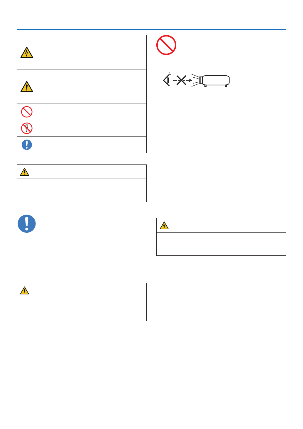
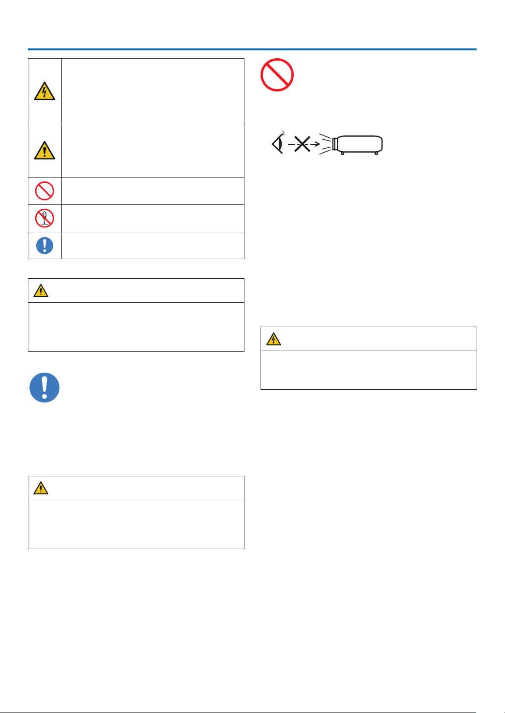
Do not do it
•Do not look into the lens while the projector is on.
Serious damage to your eyes could result.
•Keep any items such as magnifying glass out of the
light path of the projector. The light being projected
from the lens is extensive, therefore any kind of ab-
normal objects that can redirect light coming out of the
lens, can cause unpredictable outcome such as re or
injury to the eyes.
•When turning on the projector, ensure that nobody is
facing towards the lens in the path of the light emitted
from the laser.
DOC Compliance Notice (for Canada only)
This Class A digital apparatus meets all requirements of
the Canadian ICES-003 Standards.
Machine Noise Information Regulation - 3.
GPSGV,
The highest sound pressure level is less than 70 dB (A)
in accordance withENISO7779.
WARNING
This equipment is compliant with Class A of CISPR
32. In a residential environment this equipment may
cause radio interference.
ii
Important Information
CAUTION
In order to reduce any interference with radio and
television reception use a signal cable with ferrite
core attached. Use of signal cables without a ferrite
core attached may cause interference with radio and
television reception.
This equipment has been tested and found to comply
with the limits for a Class A digital device, pursuant to
Part 15 of the FCC Rules. These limits are designed to
provide reasonable protection against harmful interfer-
ence when the equipment is operated in a commercial
environment. This equipment generates, uses, and can
radiate radio frequency energy and, if not installed and
used in accordance with the installation manual, may
cause harmful interference to radio communications.
Operationofthis equipment in a residential area is
likely to cause harmful interference in which case the
user will be required to correct the interference at his
own expense.
WARNING
Do not disassemble
THE ENDUSERISNOTALLOWEDTOOPENOR
MODIFYTHEPRODUCT.
NOUSER SERVICEABLE PARTS.
MAINTENANCE AND SERVICEOFTHEPRODUCT
ISONLYTOBEHANDLEDBYNECAUTHORIZED
TECHNICIANS.
Important Safeguards
These safety instructions are to ensure the long life of
your projector and to prevent re and shock. Please read
them carefully and heed all warnings.
Installation
1. Do not point the projection beam toward other people
or reective objects.
2. Consult your distributor for information about trans-
porting and installing the projector. Do not attempt
to transport and install the projector yourself. The
projector must be installed by qualied technicians in
order to ensure proper operation and reduce the risk
of bodily injury.
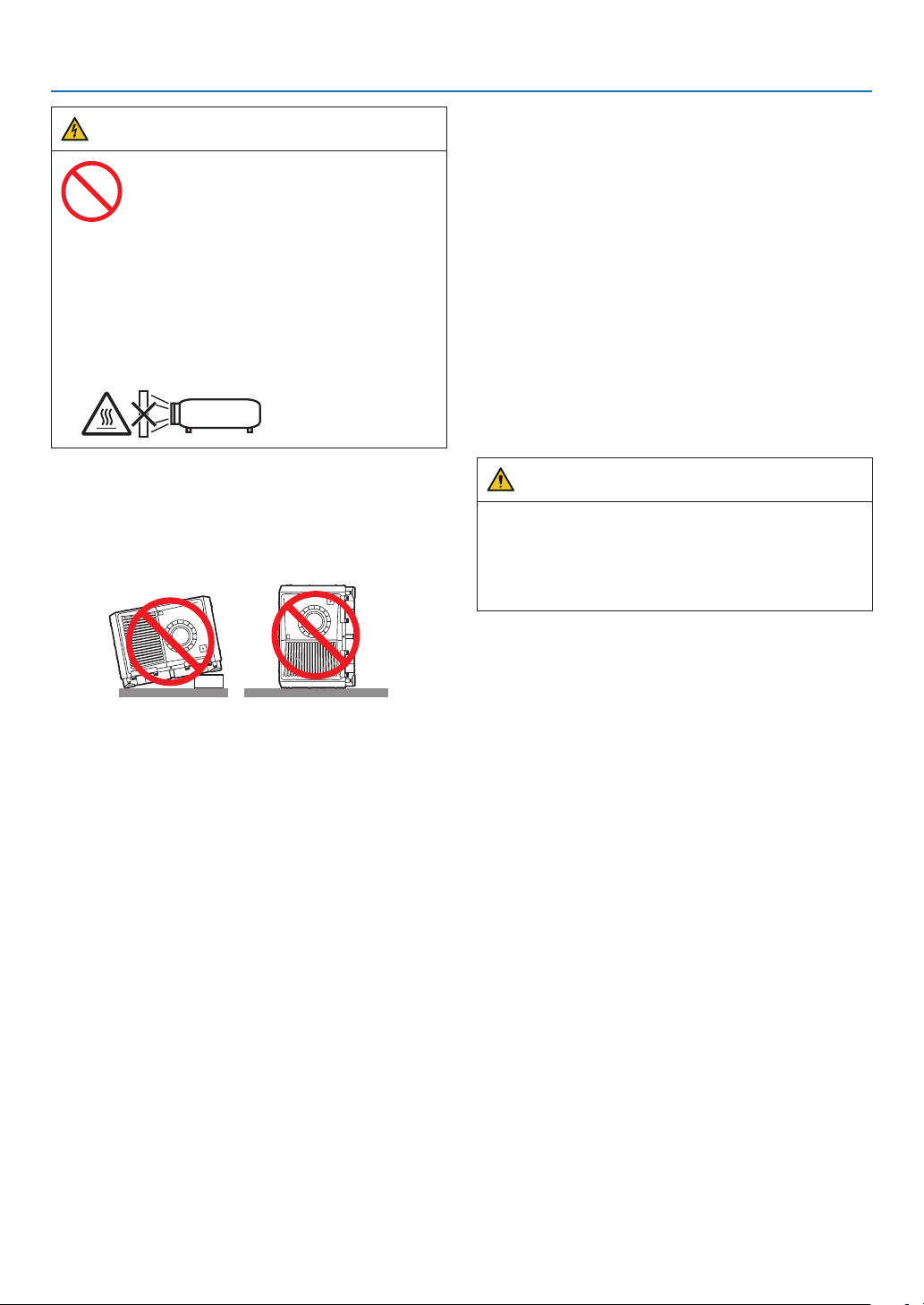
3. Place the projector on a at, level surface in a dry area
away from dust and moisture. Do not put the projector
on its side when the Laser is on. Doing so may cause
damage to the projector.
4. Do not place the projector in direct sunlight, near
heaters or heat radiating appliances.
5. Exposure to direct sunlight, smoke or steam could
harm internal components.
6. Handle your projector carefully. Dropping or jarring
your projector could damage internal components.
7. To carry the projector, a minimum of six persons are
required. Be sure to rmly grip the front and back
handles, then move the projector.
8. Do not hold the lens part withyourhand.Otherwise
the projector may tumble or drop, causing personal
injury.
9.Donotplaceheavy objects on top of the projector.
10. Turn off the projector, and disconnect the power cable
before moving the projector.
For C2 connection, turn off the projector, shut down
the AC power to the projector and the light using a cir-
cuitbreaker. Disconnect the cables between devices
and the light before moving the projector.
11. Do not install and store the projector in the below
circumstances. Failure to do so may cause of malfunc-
tion.
•Inpowerfulmagnetic elds
•Incorrosive gas environment
•Outdoors
12. If you need special installation work such as mounting
on the ceiling or suspending from the ceiling using eye
bolts:
•Do not attempt to install the projector yourself.
•Theprojector must be installed by qualied tech-
nicians in order to ensure proper operation and
reduce the risk of bodily injury.
•In addition, the ceiling must be strong enough to
support the projector and the installation must be
in accordance with any local building codes.
•Ifyouhangtheprojectorfromthehighplacesuch
as the ceiling, use fall prevention wires (commer-
cially available) to secure the lens unit in place.
Failing to do so may result in the lens unit being
loosened, causing it to fall.
•Makesureiftheprojectorisxedonthesurface
that has enough durability to stand the whole
projector weight (the projector weight including
LVunit170kgplusthelensweight9kg,i.e.,179
kg in total) for a long time.
•Pleaseconsultyour distributor for more informa-
tion.
iii
Important Information
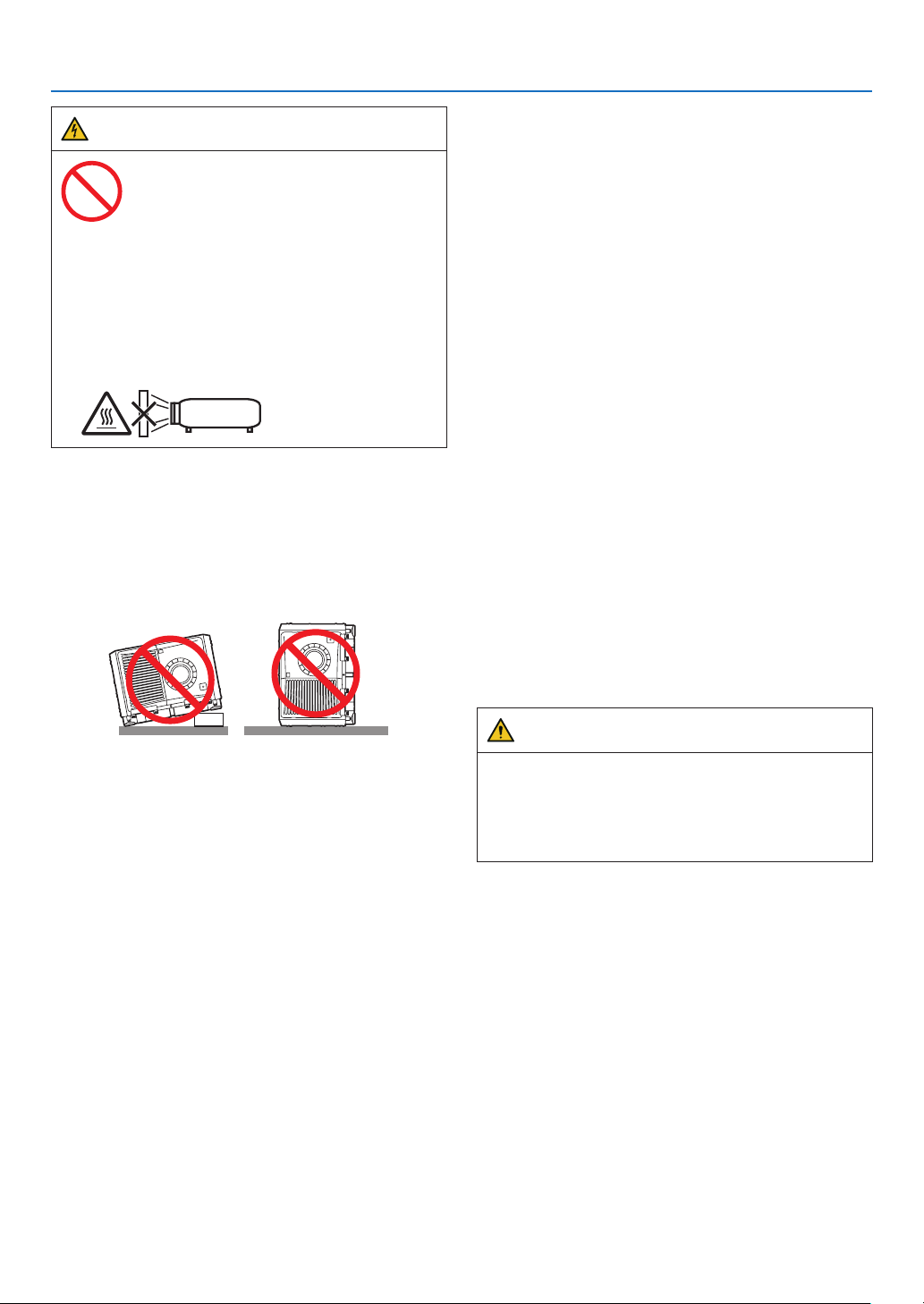
WARNING
Do not do it
1. Do not use the projector with the supplied lens cap
or equivalent while the projector is operating. This
may cause the lens cap to heat up and deform or
melt.
2. Do not place any objects, which are easily affected
by heat, in front of the projector lens. Doing so could
lead to the object melting from the heat that is emit-
ted from the light output.
It is possible to vertically set up this device at 360 degrees.
Do not use the projector with it leaning to the left and right.
This may result in a malfunction, however, portrait instal-
lation is possible. Please read the warnings concerning
portrait orientation before setting the projector in portrait
orientation.
Power Supply
1. Consult your distributor for installing the power cable
to the projector.DONOTinstallthe power cable by
yourself.Doing so may cause a re or electric shock.
The projector is so designed that it operates with the
power supply voltage described below.
For C1 connection
(When the AC power to the projector power supply and
the light power supply is provided by a single cable)
•AC200V-240V single phase 50/60Hz
For C2 connection
(When the AC power to the projector power supply
and the light power supply is provided by separate
cables)
• AC200V-240V single phase 50/60Hz (projector
power supply)
•AC200V-240V single phase 50/60Hz (light power
supply)
Ensure that your power supply ts this requirement
before attempting to use your projector.
2. The power cable is not included with the projector.
Ask your distributor for the power cable to select and
purchase. Use a power cable that meets the standards
and power supply voltage of the country where you
are using the projector.
Refer to “1-8. Connecting the Power Cable” (→ page
24) for details on connecting the power cable.
3. Handle the power cable carefully. A damaged or
frayed power cable can cause electric shock or re.
•Donot bend or tug the power cable excessively.
•Donotplacethe power cable under the projector,
or any heavy object.
•Do not cover the power cable with other soft ma-
terials such as rugs.
•Donotheat the power cable.
4. Placing the power cable and the signal cable closely
to each other can cause beat noise. If this happens,
keep the two separated so that beat noise is not
generated.
Beat noise is corruption of the picture often seen as
a rolling band moving through the image.
5. Do not touch the projector during a thunder storm.
Doing so can cause electrical shock or re.
6. When installed on the ceiling, install the breaker in a
location that is easy to reach by hand.
CAUTION
This equipment is designed to be used in the condition
of the power cable connected to earth. If the power
cable is not connected to the earth, it may cause
electric shock. Please make sure the power cable is
earthed properly.
iv
Important Information
Fire and Shock Precautions
1. Ensure that there is sufficient ventilation and that
vents are unobstructed to prevent potentially dan-
gerous concentrations of ozone and the build-up of
heat inside your projector. Allow at least 23.6 inches
(60 cm) of space between your projector and a wall.
In particular, clear a space of 27.6 inches (70 cm) or
more in front of the air outlet on the rear surface and
11.8 inches (30 cm) or more on the upper part of the
projecter body. (→ page
1)
2. Prevent foreign objects such as paper clips and bits of
paper from falling into your projector. Do not attempt
to retrieve any objects that might fall into your projec-
tor. Do not insert any metal objects such as a wire or
screwdriver into your projector. If something should
fall into your projector, shut down the AC power to the
projector immediately and have the object removed
by a qualied service person.
For C2 connection, turn off the projector, shut down
the AC power to the projector and the light using a
circuit breaker, and contact your dealer/distributor.
3. Turn off the projector, shut down AC power by using a
circuit breaker and contact qualied service personnel
under the following conditions. For C2 connection,
turn off the projector, shut down the AC power to the
projector and the light using a circuit breaker, and
contact your dealer/distributor for a repair.
•When the power cable or plug is damaged or
frayed.
•Ifliquid has been spilled into the projector, or if it
has been exposed to rain or water.
•Iftheprojector does not operate normally when
you follow the instructions described in this user’s
manual.
•Ifthe projector has been dropped or the cabinet
has been damaged.
•Iftheprojector exhibits a distinct change in per-
formance, indicating a need for service.
4. When using a LAN cable:
For safety, do not connect to the connector for periph-
eral device wiring that might have excessive Voltage.
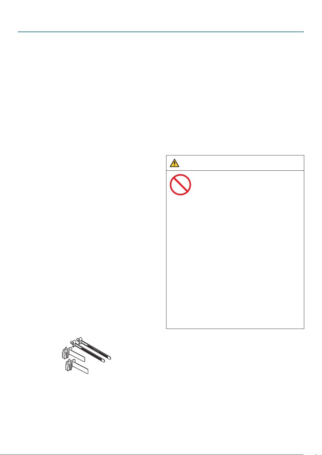
5. Make sure to mount the power cable stopper before
attempting to use your projector. Refer to page 36
about the power cable stopper.
Cleaning
1. Shut down AC power by using a circuit breaker before
cleaning.
For C2 connection, turn off the projector, shut down
the AC power to the projector and the light using a
circuit breaker.
2. Clean the cabinet periodically with a cloth. If heavily
soiled, use a mild detergent. Never use strong deter-
gents or solvents such as alcohol or thinner.
3. Use a blower or lens paper to clean the lens, and be
careful not to scratch or mar the lens.
4. Do not handle the projector and the power cable with
wet hands. Doing so can cause electrical shock or re.
5. Do not use a spray containing ammable gas to
remove dust attached to the lens and cabinet. Doing
so may result in res.
CAUTION
Do not do it
1. Do not shut down AC power to the projector under
the following conditions. Doing so can damage the
projector.
•While projecting images
•Whilecoolingafter the power is turned off.
2. Do not turn off the AC power for90secondsafter
the Laser is turnedonandwhilethePOWER
indicator is blinking green. Doing so could cause
premature Laser failure.
3. Keep hands away from the lens mounting portion
while the lens shift is in operation. Failure to do so
could result in ngers being pinched between the
cabinet and lens cover.
4. When main body is damaged, cooling uids may
come out of internalpart.DONOT touch and drink
the cooling uid.
When the cooling uids are swallowed or contacted
with your eyes, please consult with doctors imme-
diately.
v
Important Information
Caution on Carrying the Projector/
Handling the Optional Lens
When installing / removing a lens, shut down the AC
power to the projector.
When shipping the projector with the lens, remove the
lens before shipping the projector. Always attach the
dust cap to the lens whenever it is not mounted on the
projector. The lens and the lens shift mechanism may
encounter damage caused by improper handling during
transportation.
Cable information
CAUTION
For HDMI, DisplayPort, BNC, LAN, RS232C, 3D, and
GPI/O,please use a shielded cable.
Use of other cables may cause interference with radio
and television reception.
Remote Control Precautions
•Handletheremotecontrolcarefully.
•Iftheremotecontrolgetswet,wipeitdryimmediately.
•Avoidexcessiveheatandhumidity.
•Donotshort,heat,ortakeapartbatteries.
•Ifyouwillnotbeusingtheremotecontrolforalong
time, remove the batteries.
• Ensurethatyouhavethebatteries’polarity(+/−)
aligned correctly.
•Donotusenewandoldbatteriestogether,orusedif-
ferent types of batteries together.
Handling the Battery
•Takecarewhenhandlingthebattery,asitcouldcause
re, injury, or damage to surrounding objects.
- Do not short out, dismantle, or place batteries in a
re.
• Disposeofusedbatteriesaccordingtoyourlocal
regulations.
•Thereisabatterymountedontheelectroniccircuit
board within the main unit. When disposing of the
main unit, do not dismantle the device or remove the
internal circuit board, and contact the shop where
you purchased the product or your local government
agency.
Light Module
1. A light module containing multiple laser diodes is
included in the product as the light source.
2. These laser diodes are sealed in the light module.
No maintenance or service is required for the perfor-
mance of the light module.
3. End user is not allowed to replace the light module.
4. Contact qualied distributor for light module replace-
ment and further information.
Disposing of your used product
EU-wide legislation as implemented in each
Member State requires that used electrical
and electronic products carrying the mark
(left) must be disposed of separately from
normal household waste.
This includes projectors and their electrical
accessories. When you dispose of such
products, please follow the guidance of your
local authority and/or ask the shop where you
purchased the product.
After collecting the used products, they are
reused and recycled in a proper way. This
effort will help us reduce the wastes as well
as the negative impact to the human health
and the environment at the minimum level.
The mark on the electrical and electronic
products only applies to the current European
Union Member States.
For EU: The crossed-out wheeled bin implies
that used batteries should not be put to the
general household waste! There is a separate
collection system for used batteries, to allow
proper treatment and recycling in accordance
with legislation.
According to EU directive 2006/66/EC, the
battery can’t be disposed improperly. The
battery shall be separated to collect by
local service.

vi
Important Information
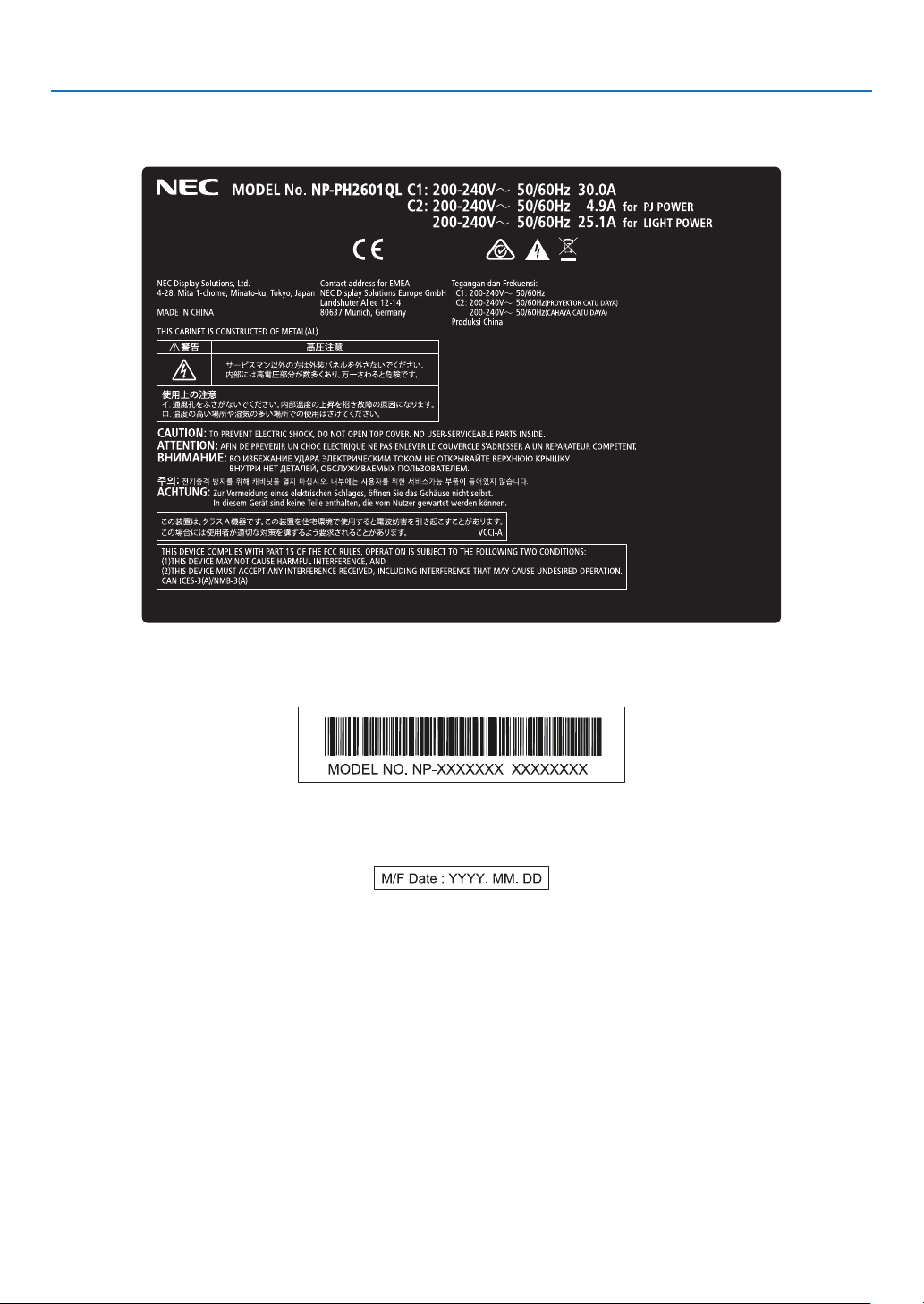
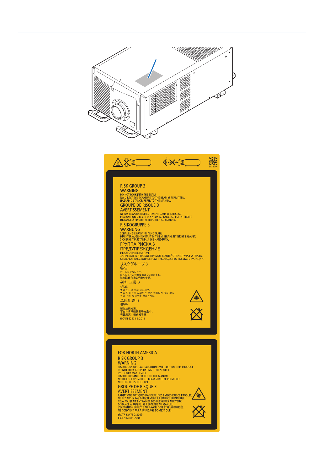
Label Information
Label A
Label A: Risk Group /Lamp Safety Label

vii
Important Information
Label C
Label D
Label ELabel B
Label B
Laser Explanatory Label
3263343400
Label C
PH3501QL
viii
Important Information
Label C
PH2601QL
Label D
Label E
ix
Important Information
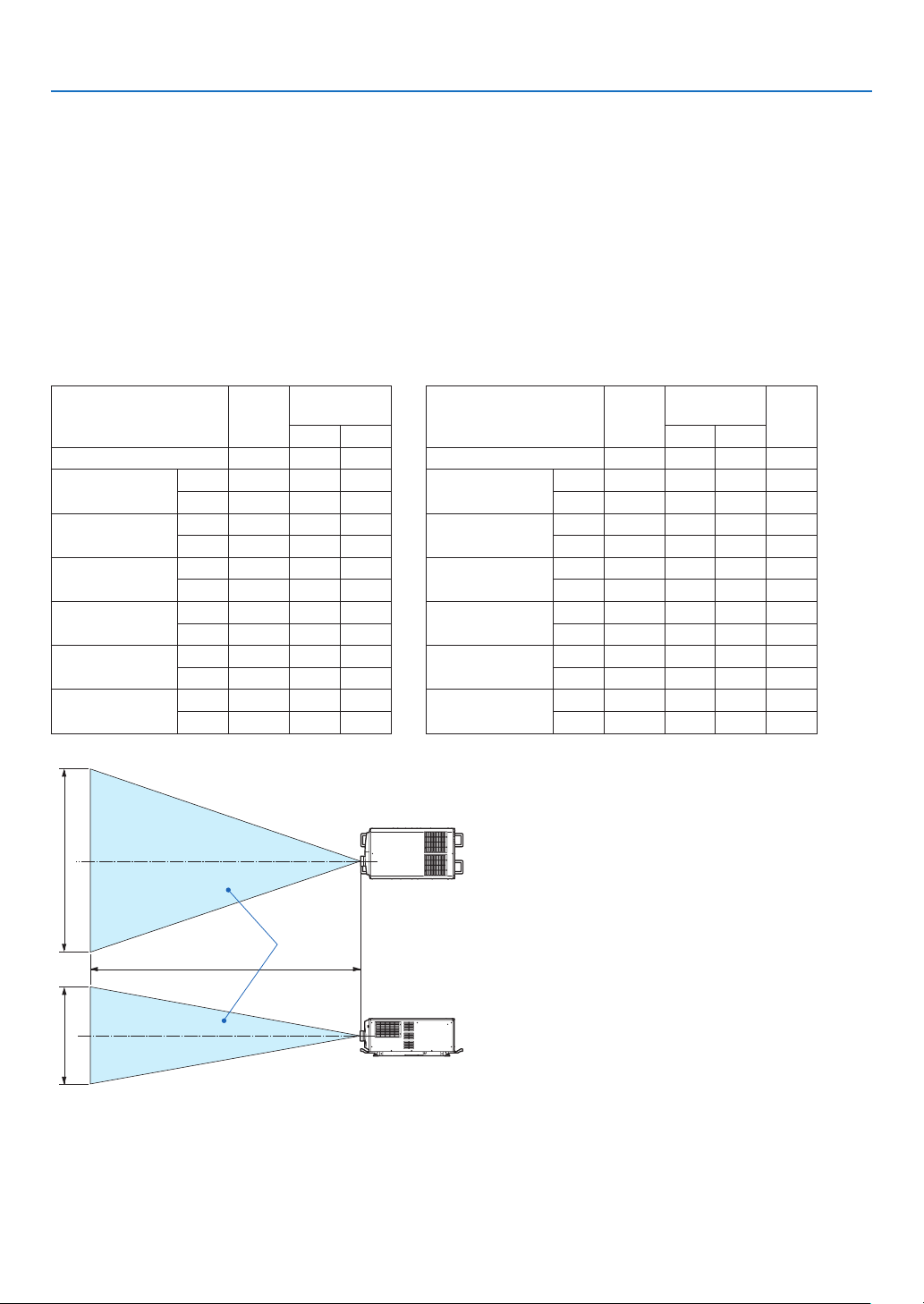
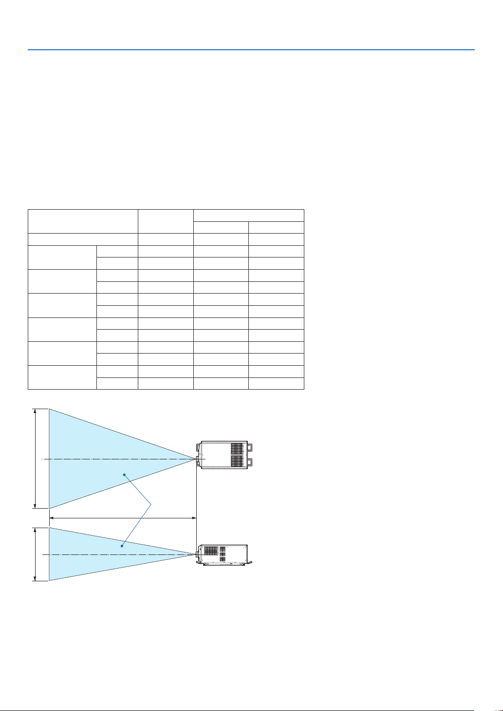
Radiation Range of Emitted Light by the Projector (HD: Hazard Distance)
•The below table describes the radiation range of emitted light by the projector that is classied as Risk Group 3
(RG3) of IEC62471-5 First edition 2015.
•The below table describes the radiation range of emitted light by the projector that is classied as Risk Group 3
(RG3) of IEC62471:2006 (for USA).
•Please keep within bounds for installing the projector.
Install a barrier for preventing human eyes from entering the RG3 area. For the barrier installation position, keep
horizontal safety zone over 1.5m from the RG3 area. In case to install the projector over head, keep over 3m dis-
tance at least between the oor surface and the RG3 area.
Operatorsshallcontrolaccesstothebeamwithinthehazarddistanceorinstalltheproductattheheightthatwill
prevent exposures of spectators’ eyes within the hazard distance.
(IEC62471-5 First edition 2015) (IEC62471:2006 (for USA))
Lens
RG3
HD(m)
Screen
size(m)
H V
L2K-10F1 4.1 4.51 2.38
L4K-11ZM
Wide 4.6 4.07 2.15
Tele 7.1 4.13 2.18
L4K-15ZM
Wide 6.2 4.28 2.25
Tele
9.14.33 2.29
L4K-20ZM
Wide 8.2 4.14 2.18
Tele 14.0 4.12 2.17
L2K-30ZM
Wide 11.0 4.07 2.15
Tele 16.0 4.10 2.16
L2K-43ZM1
Wide 16.0 4.10 2.16
Tele 22.0 4.07 2.15
L2K-55ZM1
Wide 21.0 4.20 2.21
Tele 32.0 4.16
2.19
Lens
RG3
HD(m)
Screen
size(m)
EHv
H V
L2K-10F1 4.1 4.51 2.38 10
L4K-11ZM
Wide 4.6 4.07 2.15 11
Tele 7.1 4.13 2.18 14
L4K-15ZM
Wide 6.2 4.28 2.25 12
Tele
9.14.33 2.2917
L4K-20ZM
Wide 8.2 4.14 2.18 16
Tele 14.0 4.12 2.17 17
L2K-30ZM
Wide 11.0 4.07 2.15 20
Tele 16.0 4.10 2.16 22
L2K-43ZM1
Wide 16.0 4.10 2.16 22
Tele 22.0 4.07 2.15 22
L2K-55ZM1
Wide 21.0 4.20 2.21 24
Tele 32.0 4.16
2.1927
[Plan view]
[Side view]
RG3 range
HD
H
V
* If lens shift is utilized, please consider the shift of projected image according to the volume of lens shift. (→ page
10)

x
Important Information
CAUTION
Please heed all precaution for safety.
To install the projector
•For planning the layout of the projector, make sure to take safety measures instructed on the installation manual.
•In order to refuse danger, install either a wall outlet within easy reach for pulling out the power plug in emergency
or a device as a breaker to shut down the power supply to the projector.
•Take safety measures preventing human eyes from entering the RG3 area.
•Considering the installation place, select an appropriate lens and secure safety zone that is determined for each
lens. For operation on the powered projector as light adjustment, make sure appropriate safety measures have
been taken.
•Check the validity of taken security measures if appropriate safety zone based on the installed lens is secured.
Periodically check the validity and keep these results.
•Educate the administrator of the projector (operators) about safety before starting to operate the projector.
To use the projector
•Instruct the administrator of the projector (operators) to perform inspections before powering on the projector.
(Including the safety check against emitted light by the projector)
•Instruct the administrator of the projector (operators) to be in circumstances able to control the projector when-
ever the projector is powered on for an emergency.
•Instruct the administrator of the projector (operators) to keep the installation manual, user’s manual and inspec-
tion records to a place where they can take these documents out easily.
•Instruct them to clarify if the projector is conformed to standards of each country and region.

xi
Important Information
Health precautions to users viewing 3D images
Before viewing, be sure to read health care precautions that may be found in the user’s manual included with your 3D
eyeglasses or your 3D compatible content such as Blu-ray Discs, video games, computer’s video les and the like.
To avoid any adverse symptoms, heed the following:
•Donotuse3Deyeglassesforviewinganymaterialotherthan3Dimages.
•Allowadistanceof2m/7feetorgreaterbetweenthescreenandauser.Viewing3Dimagesfromtooclosea
distance can strain your eyes.
•Avoidviewing3Dimagesforaprolongedperiodoftime.Takeabreakof15minutesorlongeraftereveryhour
of viewing.
•Ifyouoranymemberofyourfamilyhasahistoryoflight-sensitiveseizures,consultadoctorbeforeviewing3D
images.
•Whileviewing3Dimages,ifyougetsicksuchasnausea,dizziness,queasiness,headache,eyestrain,blurry
vision, convulsions, and numbness, stop viewing them. If symptoms still persist, consult a doctor.
•View3Dimagesfromthefrontofthescreen.Viewingfromananglemaycausefatigueoreyestrain.
About Copyright of original projected pictures:
Please note that using this projector for the purpose of commercial gain or the attraction of public attention in a venue
such as a coffee shop or hotel and employing compression or expansion of the screen image with the following func-
tions may raise concern about the infringement of copyrights which are protected by copyright law.
[ASPECTRATIO],Magnifyingfeatureandothersimilarfeatures.
xii
Wichtige Informationen
Dieses Symbol warnt den Benutzer vor nicht
isolierter Spannung im Innern des Geräts, die
hoch genug sein kann, um einen Stromschlag
zu verursachen. Deshalb ist es gefährlich, ei-
nen Teil im Innern dieses Geräts auf irgendeine
Weise zu berühren.
Dieses Symbol weist den Benutzer darauf
hin, dass wichtige Informationen hinsichtlich
des Betriebs und der Wartung dieses Geräts
enthalten sind. Diese sind deshalb sorgfältig
zu lesen, um jegliche Probleme zu vermeiden.
Dieses Symbol weist auf etwas hin, das ver-
boten ist.
Dieses Symbol weist auf etwas hin, das nicht
zerlegt werden darf.
Dieses Symbol weist auf etwas hin, auf das
geachtet werden muss.
ACHTUNG
ZURVERMEIDUNGEINESELEKTRISCHEN
SCHLAGSÖFFNENSIENICHTDIEOBEREAB-
DECKUNG.IMINNERENGIBTESKEINEZUWAR-
TENDEN TEILE.
Vorsichtsmaßnahmen zur Lasersicherheit
Dieses Produkt ist gemäß IEC60825-1 Dritte Auage
2014 als Klasse 1 klassiziert. Dieses Produkt ist als
RG3 von IEC62471-5 Erste Ausgabe 2015 eingestuft.
Beachten Sie bei der Installation und Verwaltung des
Geräts die Gesetze und Bestimmungen Ihres Landes.
ACHTUNG
Die Verwendung von Bedienelementen oder die
Änderung von Prozeduren in Abweichung von den in
diesem Handbuch beschriebenen könnte zu gefährli-
chem Kontakt mit Laserstrahlung führen.
•KeinedirekteExpositiongegenüberdemStrahlist
zulässig, RG3 IEC 62471-5: 2015.
Nicht tun
•SchauenSienichtindieLinse,wennderProjektor
eingeschaltet ist. Dies könnte schwere Augenverlet-
zungen zur Folge haben.
•LichtkegeldesProjektorsfern.DadasvonderLinse
projizierte Licht umfassend ist, können alle abnormalen
Gegenstände, die in der Lage sind, das aus der Linse
austretende Licht umzulenken, unvorhersehbare Er-
eignisse wie z.B. einen Brand oder Augenverletzungen
verursachen.
•WennSiedenProjektoreinschalten,stellenSiesicher,
dass sich keine Personen in dem vom Laser abgege-
benen Lichtstrahl zur Linse hingewandt benden.
Maschinenlärminformations-Verordnung –
3. GPSGV,
Der höchste Schalldruckpegel beträgt 70 dB(A) oder
wenigergemäßENISO7779.
WARNUNG
Dieses Gerät entspricht Klasse A von CISPR 32.
Dieses Produkt kann Funkstörungen in der häuslichen
Umgebung verursachen.
xiii
Wichtige Informationen
ACHTUNG
Verwenden Sie ein Signalkabel mit Ferritkern, um
Störungen beim Radio- und Fernsehempfang zu re-
duzieren. Die Verwendung eines Signalkabels ohne
Ferritkern kann Störungen beim Radio- und Fernseh-
empfang verursachen.
Durch Prüfung dieses Gerätes nach FCC, Part 15
wurde die Einhaltung der Grenzwerte für digitale
„Class A“- Geräte bestätigt. Diese Grenzwerte gelten
für einen wirksamen Schutz gegen Störungen in Ge-
werbegebieten. Dieses Gerät erzeugt und verwendet
Funkfrequenzenergie und kann diese ausstrahlen und
kann, wenn es nicht entsprechend dem Bedienungs-
handbuch aufgestellt und betrieben wird, Störungen
beim Radio- und Fernsehempfang verursachen. Die
Verwendung dieses Gerätes in Wohngebieten verur-
sacht wahrscheinlich Störungen, die der Benutzer in
eigener Verantwortung zu beseitigen hat.
WARNUNG
Nicht auseinanderbauen
DERENDBENUTZERDARFDASPRODUKTNICHT
ÖFFNENODERMODIFIZIEREN.
ESGIBTKEINEVOMBENUTZERZUWARTENDEN
TEILE.
DIEWARTUNGDESPRODUKTSDARFNURVON
NEC-AUTORISIERTENTECHNIKERNDURCHGE-
FÜHRT WERDEN.
Wichtige Sicherheitshinweise
Diese Sicherheitshinweise sollen eine lange Lebensdauer
Ihres Projektors sicherstellen und vor Feuer und elekt-
rischen Schlägen schützen. Lesen Sie diese Hinweise
sorgfältig durch und beachten Sie alle Warnungen.
Installation
1. Richten Sie den Projektionsstrahl nicht auf Personen
oder reektierende Gegenstände.
2. Wenn Sie Informationen zum Transport und zur Ins-
tallation des Projektors wünschen, wenden Sie sich
an Ihren Händler. Versuchen Sie nicht, den Projek-
torselbstzutransportierenoderzuinstallieren.Zur
Gewährleistung eines ordnungsgemäßen Betriebs
des Projektors und zur Minimierung des Risikos von
Verletzungen von Personen muss der Projektor von
qualizierten Technikern installiert werden.
3. Stellen Sie den Projektor auf eine ache, waagerechte
Fläche in einer trockenen Umgebung; frei von Staub
und Feuchtigkeit. Drehen Sie den Projektor nicht auf
die Seite, wenn der Laser eingeschaltet ist. Ande-
renfalls kann es zur Beschädigung des Projektors
kommen.
4. Stellen Sie den Projektor weder in direktes Sonnen-
licht noch in die Nähe einer Heizung oder sonstiger
Hitze abstrahlender Einrichtungen.
5. Wenn das Gerät direktem Sonnenlicht, Rauch oder
Dampf ausgesetzt wird, können interne Komponenten
beschadigt werden.
6. Behandeln Sie Ihren Projektor vorsichtig. Fallenlassen
oder starkes Schutteln kann interne Komponenten
beschädigen.
7.ZumTragendesProjektorswerdenmindestenssechs
Personen benötigt. Bewegen Sie den Projektor stets,
indem Sie ihn sicher an den vorderen und hinteren
Griffen halten.
8. Halten Sie den Projektor nicht mit der Hand am
Linsenbereich fest. Anderenfalls kann der Projektor
umkippen oder herunterfallen und Verletzungen ver-
ursachen.
9.LegenSiekeineschwerenGegenständeaufden
Projektor.
10. Schalten Sie den Projektor aus, und ziehen Sie das
Netzkabel ab, bevor Sie den Projektor umsetzen.
Für Anschluss C2 schalten Sie den Projektor aus,
und trennen Sie die Netzspannung zur Spannungs-
versorgung des Projektors und der Lichtquelle mithilfe
eines Ausschalters. Trennen Sie die Kabel zwischen
Geräten und der Lampe, bevor Sie den Projektor
bewegen.
11. Installieren und bewahren Sie den Projektor nicht
unter den nachfolgend aufgeführten Umständen auf.
Nichtbeachtung kann eine Fehlfunktion verursachen.
•InstarkenMagnetfeldern
•IneinerUmgebungmitSchadgas
•ImFreien
12. Wenn Sie spezielle Installationsarbeiten benötigen,
wie zum Beispiel die Befestigung an der Decke oder
das Aufhängen an der Decke mittels Ringschrauben:
•VersuchenSienicht,denProjektorselbstzu
installieren.
•DerProjektormussvonqualiziertemServiceper-
sonal installiert werden, um einen ordnungsgemä-
ßen Betrieb sicherzustellen und die Verletzungs-
gefahr zu reduzieren.
•DieDeckemussfürdasGewichtdesProjektors
eine ausreichende Festigkeit aufweisen und die
Installation muss entsprechend den örtlichen
Bauvorschriften ausgeführt werden.
•WennSiedenProjektoraneinerhohenStellewie
zum Beispiel von einer Decke aufhängen, verwen-
den Sie (handelsübliche) Fallschutzkabel, um die
Objektiveinheitzusichern.Andernfallskannsich
dieObjektiveinheitlösenundherunterfallen.
•StellenSiesicher,dassderProjektoraufeiner
ausreichendhaltbarenOberächebefestigtist,
um das gesamte Projektorgewicht (das Projek-
torgewicht einschließlich LV-Einheit 170 kg plus
dasObjektivgewicht9kg,d.H.Insgesamt179kg)
lange zu halten.
•WeitereInformationenerhaltenSievonIhrem
Fachhändler.
xiv
Wichtige Informationen
WARNUNG
Nicht tun
1. Verwenden Sie den Projektor nicht, während die
mitgelieferte Linsenkappe oder Ähnliches ange-
bracht ist, und der Projektor in Betrieb ist. Andern-
falls kann sich die Linsenkappe oder Glasschutz-
kappe erhitzen und sich verformen oder schmelzen.
2.PlatzierenSiekeinehitzeempndlichenObjektevor
der Projektorlinse. Dies könnte zum Schmelzen des
ObjektsdurchdieHitzeamLichtausgangführen.
Dieses Gerät kann in vertikaler Position 360° gedreht
angebracht werden.
Verwenden Sie den Projektor nicht, wenn er nach links
oder rechts geneigt ist. Dies kann zu einer Fehlfunktion
führen, die Installation im Hochformat ist jedoch möglich.
Bitte lesen Sie die Warnhinweise für die Installation im
Hochformat, bevor Sie den Projektor im Hochformat
installieren.
Spannungsversorgung
1.ZumInstallierendesNetzkabelsamProjektorwenden
Sie sich bitte an Ihren Fachhändler. UNTER KEINEN
UMSTÄNDEN versuchen, das Netzkabel selbst zu
installieren. Brand- und Schlaggefahr.
Der Projektor wurde so konzipiert, dass er mit der
unten aufgeführten Netzspannung läuft.
Für Anschluss C1
(Wenn die Netzspannung zur Spannungsversorgung
des Projektors und der Lichtquelle über ein einzelnes
Kabel zugeführt wird)
•AC200V-240Veinphasig50/60Hz
Für Anschluss C2
(Wenn die Netzspannung zur Spannungsversorgung
des Projektors und der Lichtquelle über getrennte
Kabel zugeführt wird)
•AC200V-240Veinphasig50/60Hz(Spannungs-
versorgung zum Projektor)
•AC200V-240Veinphasig50/60Hz(Spannungs-
versorgung zur Lichtquelle)
Stellen Sie sicher, dass die vorhandene Spannungs-
versorgung diesen Vorgaben entspricht, bevor Sie
versuchen, Ihren Projektor zu betreiben.
2. Es wird kein Netzkabel mit dem Projektor geliefert.
Fragen Sie Ihren Händler, welches Netzkabel aus-
zuwählen und zu kaufen ist. Verwenden Sie ein
Netzkabel, das die Normen und Netzspannung des
Landes, in dem der Projektor verwendet wird, erfüllt.
Siehe„1-9.AnschließendesNetzkabels“(→ Seite
38)
für Einzelheiten zum Anschließen des Netzkabels.
3. Behandeln Sie das Netzkabel vorsichtig. Ein be-
schädigtes oder durchgescheuertes Netzkabel kann
elektrische Schläge oder einen Brand verursachen.
•BiegenoderziehenSiedasNetzkabelnichtüber-
mäßig.
•LegenSiedasNetzkabelnichtunterdenProjektor
oder unter einen anderen schweren Gegenstand.
•BedeckenSiedasNetzkabelauchnichtmitwei-
chen Materialien, z. B. mit Teppichen.
•ErhitzenSiedasNetzkabelnicht.
4. Wenn Sie das Netzkabel und das Signalkabel in
unmittelbarer Nähe zueinander platzieren, kann
Überlagerungsrauschen auftreten. Vergrößern Sie in
einem derartigen Fall den Abstand zwischen diesen
beiden Kabeln.
Bildrauschen ist ein Bildfehler, der oft als rollendes
Band durch das Bild sichtbar wird.
5. Berühren Sie den Projektor auf keinen Fall während
eines Gewitters. Wenn Sie dies nicht beachten, kann
dies zu einem elektrischen Schlag oder einem Feuer
führen.
6. Wenn der Projektor an der Decke montiert wird, in-
stallieren Sie den Leistungsschalter an einer Stelle,
die von Hand leicht erreichbar ist.
VORSICHT
Diese Ausrüstung ist für den Gebrauch mit einem geer-
deten Netzkabel entworfen. Wenn das Netzkabel nicht
geerdet ist, kann dies zu einem elektrischen Schlag
führen. Bitte achten Sie darauf, dass das Netzkabel
ordnungsgemäß geerdet ist.
xv
Wichtige Informationen
Vorsichtsmasnahmen zur Vermeidung von
Bränden und elektrischen Schlägen
1. Sorgen Sie für ausreichende Belüftung und stellen
Sie außerdem sicher, dass die Lüftungsschlitze frei
bleiben, damit sich innerhalb des Projektors kein
Hitzestau bilden kann. Lassen Sie mindestens 60 cm
Abstand zwischen Ihrem Projektor und der Wand. Hal-
ten Sie insbesondere einen Freiraum von mindestens
70 cm vor dem Luftauslass auf der Rückseite und von
mindestens 30 cm oberhalb des Projektorgehäuses.
(→ Seite
3)
2. Vermeiden Sie, dass Fremdgegenstande wie Bü-
roklammern und Papierschnipsel in den Projektor
fallen. Versuchen Sie nicht, in den Projektor gefallene
Gegenstände selbst zu entfernen. Stecken Sie keine
Metallgegenstände wie einen Draht oder Schrauben-
dreher in Ihren Projektor. Wenn etwas in den Projektor
gefallen ist, schalten Sie sofort die Stromversorgung
des Projektors ab, und lassen Sie den Gegenstand
von qualiziertem Servicepersonal entfernen.
Für Anschluss C2 schalten Sie den Projektor aus,
trennen Sie die Netzspannung zur Spannungsversor-
gung des Projektors und der Lichtquelle mithilfe eines
Ausschalters und wenden Sie sich an Ihren Händler/
Lieferanten.
3. Schalten Sie den Projektor aus, ziehen Sie den Netz-
stecker und kontaktieren Sie unter den folgenden
Bedingungen qualiziertes Service-Personal.
Für Anschluss C2 schalten Sie den Projektor aus,
trennen Sie die Netzspannung zur Spannungsver-
sorgung des Projektors und der Lichtquelle mithilfe
eines Ausschalters und wenden Sie sich für Repara-
turarbeiten an Ihren Händler/Lieferanten.
•WenndasNetzkabeloderderNetzsteckerbe-
schädigt oder ausgefranst ist.
•FallsFlüssigkeitindenProjektorgelangtist,oder
wenn er Regen oder Wasser ausgesetzt war.
•FallsderProjektornichtnormalarbeitet,obwohl
Sie die in diesem Bedienungshandbuch beschrie-
benen Anleitungen befolgen.
•WennderProjektorfallengelassenoderdasGe-
häuse beschädigt wurde.
•WennderProjektoreineeindeutigeLeistungsver-
änderung aufweist, die einer Wartung bedarf.
4. Wenn ein LAN-Kabel verwendet wird:
Schließen Sie es aus Sicherheitsgründen nicht an
den Anschluss der Peripheriegeräte-Verbindung an,
das sie eine zu hohe Spannung führen könnte.
5. Bringen Sie stets den Netzkabelverschluss an, bevor
Sie versuchen, Ihren Projektor zu benutzen. Siehe
Seite 50 Wissenswertes über den Netzkabelver-
schluss.
Reinigung
1. Schalten Sie vor der Reinigung die Stromversorgung
durch Herausdrehen der Sicherung ab.
Für Anschluss C2 schalten Sie den Projektor aus und
trennen Sie die Netzspannung zur Spannungsversor-
gung des Projektors und der Lichtquelle mithilfe eines
Ausschalters.
2. Reinigen Sie das Gehäuse regelmäßig mit einem
Tuch. Bei starker Verschmutzung verwenden Sie
ein mildes Reinigungsmittel. Reinigen Sie das Gerät
niemals mit starken Reinigungsoder Lösungs-mitteln
wiez.B. Alkohol oder Verdünner.
3. Reinigen Sie die Linse mit einer Blaseinrichtung oder
einem Linsentuch. Beachten Sie dabei, dass die
Linsenoberäche weder zerkratzt noch auf andere
Weise beschädigt wird.
4. Berühren Sie den Projektor oder das Netzkabel nicht
mit nassen Händen. Andernfalls kann es zu elektri-
schen Schlägen oder zu einem Brand kommen.
5. Verwenden Sie kein Sprühmittel, das ein brennbares
Gasenthält,umdenamObjektivundGehäuseanhaf-
tenden Staub zu entfernen. Dadurch können Brände
entstehen.
ACHTUNG
Nicht tun
1. In den folgenden Situationen darf die Netzspan-
nung nicht getrennt werden. Der Projektor könnte
sonst beschädigt werden.
•WährendderProjizierungvonBildern
•WährenddesAbkühlensnachAusschaltender
Stromzufuhr.
2.SchaltenSiedenWechselstrom90Sekundenlang
nicht aus, nachdem der Laser eingeschaltet wurde
undwährenddiePOWER-Anzeigegrünblinkt.
Anderenfalls könnte der Laser vorzeitig ausfallen.
3. Halten Sie die Hände fern vom Linsenmontageteil,
während der Linsenversatz in Betrieb ist. Ande-
renfalls könnten Finger zwischen Gehäuse und
Linsendeckel eingeklemmt werden.
4. Wenn das Hauptteil beschädigt ist, kann Kühlungs-
üssigkeit aus dem Inneren austreten. Berühren
Sie die Flüssigkeit NICHT, und trinken Sie sie
NICHT.
Wenn die Kühlungsüssigkeit geschluckt wurde
oder in Augenkontakt kam, rufen Sie bitte sofort
einen Arzt.
xvi
Wichtige Informationen
Vorsicht beim Transportieren des
Projektors/Umgang mit der optischen
Linse
WennSieeinObjektivinstallieren/entfernen,schalten
Sie die Stromversorgung des Projektors ab.
Wenn Sie den Projektor mit der Linse verschicken, ent-
fernen Sie die Linse vor dem Versand. Bringen Sie immer
die Staubschutzkappe an der Linse an, wenn diese nicht
am Projektor angebracht ist. Die Linse und der Lens Shift
Mechanismus können durch unsachgemäße Handha-
bung während des Transports beschädigt werden.
Kabelinformationen
VORSICHT
Für HDMI, DisplayPort, BNC, LAN, RS232C, 3D und
GPI/OverwendenSiebitteeinabgeschirmtesKabel.
Das Verwenden anderer Kabel kann Störungen beim
Fernseh- und Rundfunkempfang verursachen.
Vorsichtsmaßnahmen zur Fernbedienung
•BehandelnSiedieFernbedienungmitSorgfalt.
•WischenSiedieFernbedienungsoforttrocken,wenn
sie einmal nass geworden sein sollte.
•VermeidenSieübermäßigeHitzeundFeuchtigkeit.
•SchließenSiedieBatteriennichtkurz,erhitzenSiesie
nicht und nehmen Sie sie nicht auseinander.
•NehmenSiedieBatterienheraus,wennSiebeabsichti-
gen,dieFernbedienungübereinenlängerenZeitraum
hinweg nicht zu benutzen.
•StellenSiesicher,dassdieBatteriepole(+/−)richtig
ausgerichtet sind.
•VerwendenSieniemalsverschiedeneBatterietypen
oder neue und alte Batterien zusammen.
Umgang mit der Batterie
•SeienSieausserstvorsichtigbeimHantierenderBat-
terie, um jedes Risiko von Brand, Verletzungen oder
BeschadigungenandererObjekte.
- Die Batterien nicht kurzschliessen, demontieren oder
ins Feuer werfen.
•EntsorgenSieverbrauchteBatterienentsprechend
den in Ihrem Land geltenden Bestimmungen.
•AufderLeiterplattederHaupteinheitisteineBatterie
montiert.
ZerlegenSiedieHaupteinheitbeimEntsorgennicht,
und entfernen Sie nicht die interne Leiterplatte. Wen-
den Sie sich stattdessen an den Handler, bei dem Sie
das Gerat erworben haben, oder an die zustandige
Behorde.
Lichtmodul
1. Als Lichtquelle dient dem Produkt ein Lichtmodul
bestehend aus mehreren Laserdioden.
2. Diese Laserdioden sind im Lichtmodul eingeschlos-
sen. Für die Leistung des Lichtmoduls ist keine War-
tung erforderlich.
3. Der Endbenutzer darf das Lichtmodul nicht austau-
schen.
4. Wenden Sie sich an einen qualizierten Händler, wenn
Sie das Lichtmodul austauschen wollen oder weitere
Informationen benötigen.
Entsorgung Ihres benutzten Gerätes
Die EU-weite Gesetzgebung, wie sie in jedem
einzelnen Mitgliedstaat gilt, bestimmt, dass
benutzte elektrische und elektronische Geräte
mit dieser Markierung (links) getrennt vom
normalen Haushaltsabfall entsorgt werden
müssen.
Dies schließt Projektoren und deren elek-
trischesZubehörmitein.FolgenSiebeim
Entsorgen eines solchen Gerätes bitte den
Anweisungen Ihrer örtlichen Behörde und/
oder konsultieren Sie den Händler, bei dem
Sie das Gerät erworben haben.
Nach der Sammlung benutzter Geräte werden
diese erneut verwendet und entsprechend
den Umweltbestimmungen recycelt. Das
trägt dazu bei, die Abfallmenge sowie die
negativen Auswirkungen auf die menschliche
Gesundheit und die Umwelt auf ein Minimum
zu reduzieren.
Die Markierung auf elektrischen und elektroni-
schen Geräten gilt nur für die gegenwärtigen
Mitgliedstaaten der Europäischen Union.
Für die EU: Der durchgestrichene Abfallbe-
hälter bedeutet, dass verbrauchte Batterien
nicht über den allgemeinen Hausmüll entsorgt
werden dürfen. Es gibt ein getrenntes Sam-
melsystem für Altbatterien, um die ordnungs-
gemäße Behandlung und Wiederverwertung
entsprechend den geltenden Vorschriften zu
ermöglichen.
Gemäß der Richtlinie 2006/66/EG dürfen
Batterien nicht auf ungeeignete Weise
entsorgt werden. Die Batterie muss ge-
trennt durch einen örtlichen Entsorger
gesammelt werden.
xvii
Wichtige Informationen
Etiketteninformationen
Aufkleber A
Aufkleber A: Lampe Warnzeichen Etikette

xviii
Wichtige Informationen
Aufkleber C
Aufkleber D
Aufkleber EAufkleber B
Aufkleber B
Laser erklärendes Etikett
3263343400
Aufkleber C
PH3501QL

xix
Wichtige Informationen
Aufkleber C
PH2601QL
Aufkleber D
Aufkleber E
xx
Wichtige Informationen
Strahlungsbereich des abgegebenen Lichts durch den Projektor(Sicherheitsabstand –
HD: Hazard distance)
•DienachfolgendabgebildeteTabellegibtdenStrahlungsbereichdesabgegebenenLichtsdurchdenProjektoran,
das als Risikogruppe 3 (RG3) nach IEC62471-5 Erste Ausgabe 2015 eingestuft.
•BittebeiderInstallationdesProjektorsdieEinschränkungenbeachten.
Installieren Sie zum Schutz der menschlichen Augen vor dem RG3-Bereich eine Abdeckung. Achten Sie darauf,
dass sich bei der Installation der Abdeckung die horizontale Sicherheitszone mindestens 1,5 m vom RG3-Bereich
entfernt bendet. Falls der Projektor über Kopf installiert wird, halten Sie einen Abstand von mindestens 3 m zwi-
schen der Bodenäche und dem RG3-Bereich ein.
BedienermüssendenZugangzumStrahlinnerhalbdesGefahrenabstandskontrollierenoderdasProduktsohoch
installieren,dassdieAugenderZuschauerinnerhalbdesGefahrenabstandsnichtdemStrahlausgesetztwerden
können.
Linse RG3 HD (m)
Bildschirmgröße (m)
H V
L2K-10F1 4,1 4,51 2,38
L4K-11ZM
Breit 4,6 4,07 2,15
Tele 7,1 4,13 2,18
L4K-15ZM
Breit 6,2 4,28 2,25
Tele
9,14,33 2,29
L4K-20ZM
Breit 8,2 4,14 2,18
Tele 14,0 4,12 2,17
L2K-30ZM
Breit 11,0 4,07 2,15
Tele 16,0 4,10 2,16
L2K-43ZM1
Breit 16,0 4,10 2,16
Tele 22,0 4,07 2,15
L2K-55ZM1
Breit 21,0 4,20 2,21
Tele 32,0 4,16
2,19
[Draufsicht]
[Seitenansicht]
RG3-Bereich
HD
H
V
* Falls der Linsenversatz verwendet wird, berücksichtigen Sie bitte die Verschiebung des projizierten Bildes je nach Umfang des
Linsenversatzes. (→ Seite
10)

xxi
Wichtige Informationen
WARNUNG
Bitte beachten Sie alle Sicherheitshinweise.
Installation des Projektors
•BeachtenSiebeiderPlanungdesAufbausdesProjektorsdieSicherheitsmaßnahmenimInstallationshandbuch.
•InstallierenSiezurGefahrenverringerungeineWandsteckdoseinReichweite,damitderNetzsteckerimNotfall
herausgezogen werden kann, oder einen Trennschalter, um die Stromversorgung zum Projektor unterbrechen
zu können.
•BeachtenSiezumSchutzdermenschlichenAugenvordemRG3-BereichdieSicherheitsmaßnahmen.
•WählenSieeinegeeigneteLinsefürdenInstallationsortaus,undhaltenSiedieSicherheitszone,diefürdie
jeweilige Linse vorgesehen ist, ein. Beachten Sie die entsprechenden Sicherheitsmaßnahmen, wenn Sie Ein-
stellungen am Licht des eingeschalteten Projektors vornehmen.
•PrüfenSie,obdieSicherheitsmaßnahmeneingehaltenwurden,wenndieentsprechendeSicherheitszonegemäß
der installierten Linse eingestellt wird. Prüfen Sie dies in regelmäßigen Abständen und dokumentieren Sie die
Ergebnisse.
•WeisenSiedenAdministratordesProjektors(Bediener)indieSicherheitsbestimmungenein,bevordiesermit
dem Betrieb des Projektors beginnt.
Verwendung des Projektors
•WeisenSiedenAdministratordesProjektors(Bediener)an,denProjektorvordemEinschaltenzuüberprüfen
(einschließlich der Sicherheitsprüfung des abgegebenen Lichts durch den Projektor).
•UnterrichtenSiedenAdministratordesProjektors(Bediener)überdieerforderlichenMaßnahmenzurKontrolle
des eingeschalteten Projektors, falls ein Notfall eintritt.
•WeisenSiedenAdministratordesProjektors(Bediener)an,dasInstallationshandbuch,dasBenutzerhandbuch
unddieInspektionsdokumenteaneinemOrtzuverwahren,andemleichtaufdieseDokumentezugegriffen
werden kann.
•WeisenSieihnan,zuprüfen,obderProjektordenStandardsdesentsprechendenLandesundderjeweiligen
Region entspricht.

xxii
Wichtige Informationen
Vorsichtsmaßnahmen zur Gesundheit bei der Betrachtung von 3D-Bildern
Bevor Sie 3D-Bilder betrachten, lesen Sie unbedingt die Vorsichtsmaßnahmen zu Gesundheitsrisiken, die Sie im
Benutzerhandbuch Ihrer 3D-Brillen oder Ihrer 3D-kompatiblen Medien wie Blu-ray-Disks, Videospiele, Compu-
tervideodateien und dergleichen nden.
ZurVermeidungvongesundheitsbeeinträchtigendenSymptomenbeachtenSieFolgendes:
•VerwendenSiekeine3D-BrillenzumBetrachtenvonanderenMaterialienals3D-Bildern.
•LassenSieeinenAbstandvon2m/7FußodermehrzwischendemBildschirmundBenutzer.DasAnsehenvon
3D-Bildern aus zu naher Entfernung kann Ihre Augen belasten.
•VermeidenSiedasBetrachtenvon3D-BildernübereinenlängerenZeitraumhinweg.MachenSienachjeder
Stunde eine Pause von 15 Minuten.
•FallsSieodereinMitgliedIhrerFamilieschondurchLichtausgelösteKrampfanfällehatten,fragenSieeinen
Arzt, bevor Sie 3D-Bilder betrachten.
•WennwährenddesBetrachtensvon3D-BildernSymptomewieÜbelkeit,Schwindel,Brechreiz,Kopfschmerzen,
Augenschmerzen, verschwommene Sicht, Krämpfe oder Taubheitsgefühl auftreten, brechen Sie das Betrachten
ab. Wenn die Symptome anhalten, suchen Sie einen Arzt auf.
•BetrachtenSie3D-BildervonvorneaufdemBildschirm.AnsichtvonderSeitekannzuErmüdungoderÜber-
anstrengung der Augen führen.
Zum Urheberrecht von original projizierten Bildern:
BittebeachtenSie,dassbeiderVerwendungdiesesProjektorsfürkommerzielleZweckeoderzurErregungderAuf-
merksamkeitaneinemöffentlichenOrt,z.B.ineinemCaféoderineinemHotel,eineKomprimierungoderDehnung
des Bildes mit den Funktionen als Verletzung bestehender und gesetzlich geschützter Urheberrechte ausgelegt
werden kann.
[BILDFORMAT],Vergrößerungs-undandereähnlicheFunktionen.

xxiii
Table of Contents
Introduction ................................................................................................................. b
Important Information ............................................................................................i
Wichtige Informationen ...................................................................................... xii
1. Before Setting Up Your Projector .............................................................1
1-1. Clearance for Installing the Projector (English) .............................................................1
1-2. Freiraum bei der Projektorinstallation (Deutsch) ...........................................................3
1-3. Selecting the lens unit ..................................................................................................5
1-4. Carrying the projector .................................................................................................12
1-5. Removing and Mounting the Projector Covers............................................................13
1-5-1. Removing and Mounting the Lens Cover .......................................................15
1-5-2. Removing and Mounting the Side Panel .......................................................17
1-5-3. Removing and Mounting the Filter Cover ......................................................17
1-6. Selecting the Power Cable for C2 Connection (English) .............................................18
1-7. Auswahl des Netzkabels für Anschluss C2 (Deutsch) .................................................21
1-8. Connecting the power cable (English) ........................................................................24
1-8-1. Power supply construction specications ......................................................24
1-8-2. Procedure for connecting the power cable (C1 connection) ..........................31
1-8-3. Procedure for connecting the power cable (C2 connection) ..........................34
1-9.AnschließendesNetzkabels(Deutsch) ......................................................................38
1-9-1.TechnischeDatenzumNetzanschluss .........................................................38
1-9-2.AnschlussdesStromkabels(AnschlussC1) .................................................45
1-9-3.AnschlussdesStromkabels(AnschlussC2) .................................................48
2. Configuring the projector’s initial settings .......................................52
2-1. Initial settings ow ....................................................................................................... 52
2-2. Updating the software ................................................................................................52
2-2-1. Update ow....................................................................................................52
2-2-2. Installing the DCC on the computer ..............................................................53
2-2-3. Connecting the computer to the projector and starting up the DCC .............54
2-2-4. Updating the projector ..................................................................................56
2-2-5. Exiting the DCC ............................................................................................58
2-3. Installing the LV unit ...................................................................................................59
2-4. Attaching the controls/indicator panel display label ....................................................61
3. Setting Up Your Projector ...........................................................................62
3-1. Setup Procedure .........................................................................................................62
3-2. Installing the projector ................................................................................................63
3-3. Mounting the Lens Unit ..............................................................................................64
4. Projector Adjustment and Connecting ................................................69
4-1. Flow of Adjustment and Connecting ...........................................................................69
4-2. Turning on the Projector .............................................................................................70
4-3. Selecting the projector orientation .............................................................................. 74

xxiv
Table of Contents
4-4. Adjusting the Picture Size and Position ......................................................................75
4-4-1. Adjustment of the projector’s settings (Level adjusters) .................................76
4-4-2. Adjusting the vertical position of a projected image (Lens shift) ...................77
4-4-3. Focus ............................................................................................................79
4-4-4.Zoom.............................................................................................................81
4-5.ConnectingtoOtherEquipments ...............................................................................82
4-5-1. Connecting to external equipments ...............................................................82
4-5-2.MountingtheOptionalBoard(soldseparately) .............................................84
4-6. Turning off the Projector ..............................................................................................85
5. List of Menu Items ..........................................................................................87
6. Maintenance .......................................................................................................93
6-1. Cleaning the Cabinet ..................................................................................................93
6-2. Cleaning the Lens ......................................................................................................93
6-3. Cleaning the Air Filters ...............................................................................................94
6-3-1. Cleaning the Air Filter ....................................................................................94
6-3-2. Resetting the Air Filter Usage Time ............................................................... 97
7. Appendix ................................................................................................................98
7-1. Compatible Input Signal List .......................................................................................98
7-2. Indicator Messages ..................................................................................................100
7-3. Pin assignments and signal names of main terminals ..............................................103
7-4. Remote Interlock Connector .....................................................................................108
7-5. About the ASCII Control Command .......................................................................... 11 0
7-6. OutlineDrawing ........................................................................................................ 112
7- 7. Special Installation .................................................................................................... 113
7-7- 1. Installing the Projector on the Ceiling ........................................................... 113
7-7-2 Installing using eye bolts .............................................................................. 114
7-7-3. Installation for free tilting or portrait projecting ............................................. 115
7-7-4. Multi-Screen Projection ................................................................................ 117
7-8. Using the DCC’s functions ........................................................................................ 118
7-8-1. Description of the Sections in the screen .................................................... 118
7-8-2. Switching the operating mode .....................................................................122
7-8-3. Checking Information of the Projector and Logs .........................................124
7-8-4. Creating logs ...............................................................................................134

1
1. Before Setting Up Your Projector
1-1. Clearance for Installing the Projector (English)
Allow ample clearance between the projector and its surroundings as shown below.
The high temperature exhaust coming out of the device may be sucked into the device again.
Avoid installing the projector in a place where air movement from the HVAC is directed at the projector.
Heated air from the HVAC can be taken in by the projector's intake vent. If this happens, the temperature inside the
projector will rise too high causing the over-temperature protector to automatically turn off the projectors power.
Intake vent
Exhaust vent
Intake vent
Intake vent Exhaust vent
Exhaust vent
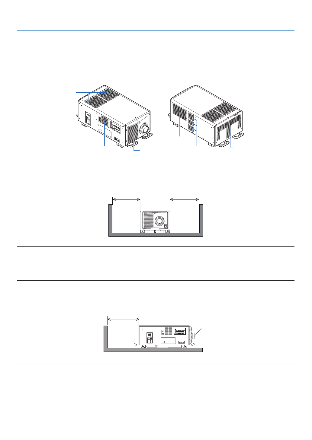
Installation conditions for the projector
Example 1 – If there are walls on both sides of the projector.
60 cm/23.6" or greater 60 cm/23.6" or greater
NOTE:
•Thedrawingshowstheproperclearancerequiredforthefront,back,andtopoftheprojector.
•Theabovedrawingcanalsobeappliedtotherequiredclearancebetweenintakeventandtheoorfortheportraitprojection.
•Seepage115foraninstallationexampleonportraitprojection.
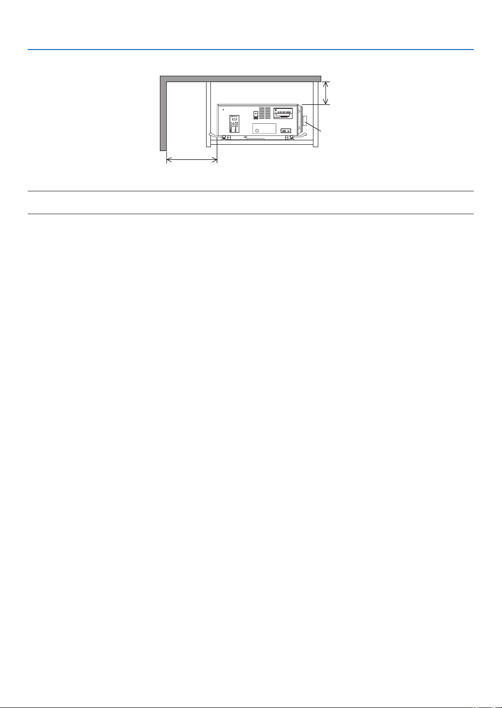
Example 2 – If there is a wall behind the projector.
(1) For oor installation:
70 cm/27.6" or greater
Lens
NOTE:
•Thedrawingshowstheproperclearancerequiredfortheright,left,andtopoftheprojector.
2
1. Before Setting Up Your Projector
(2) For ceiling mounting:
Lens
70 cm/27.6" or greater
30 cm/11.8" or greater
NOTE:
•Thedrawingshowstheproperclearancerequiredforthefront,right,left,andbottomoftheprojector.
3
1. Before Setting Up Your Projector
1-2. Freiraum bei der Projektorinstallation (Deutsch)
Sorgen Sie für ausreichend Abstand zwischen dem Projektor und der Umgebung wie unten abgebildet.
Die mit hoher Temperatur aus dem Gerät ausströmende Abluft könnte wieder in das Gerät eingesaugt werden.
Installieren Sie den Projektor nicht in einer Position, wo die Luft aus einer Klimaanlage auf den Projektor trifft.
Heiße Luft aus einer Klimaanlage kann von den Lüftungsöffnungen des Projektors aufgenommen werden. In diesem
Fall steigt die Innentemperatur des Projektors zu hoch und der Überhitzungsschutz wird den Projektor abschalten.
Eintrittsöffnung
Austrittsöffnung
Eintrittsöffnung
Eintrittsöffnung Austrittsöffnung
Austrittsöffnung
Bedingungen für die Installation des Projektors
Beispiel 1 – Wenn sich Wände auf beiden Seiten des Projektors benden.
60 cm oder mehr 60 cm oder mehr
HINWEIS:
•DieAbbildungzeigtdenordnungsgemäßenAbstandfürdieVorder-,Rück-undOberseitedesProjektors.
•DieobigeZeichnungkannauchfürdenerforderlichenAbstandzwischenderEintrittsöffnungunddemBodenbeiderAusrichtung
imHochformatverwendetwerden.
•EinEinbaubeispielfürdieProjektionimHochformatndenSieaufSeite115.
Beispiel 2 – Wenn sich eine Wand hinter dem Projektor bendet.
(1) Für Bodeninstallation:
70 cm oder mehr
Linse
HINWEIS:
•DieZeichnungzeigtdenrichtigenAbstanddesProjektorsnachrechts,linksundobenan.

4
1. Before Setting Up Your Projector
(2) Für Deckenmontage:
Linse
70 cm oder mehr
30 cm oder mehr
HINWEIS:
•DieZeichnungzeigtdenrichtigenAbstanddesProjektornachvorn,rechts,linksunduntenan.
5
1. Before Setting Up Your Projector
1-3. Selecting the lens unit
This section provides the guideline information on how to select a screen size, projector mounting position, and type
of lens units, which is appropriate for your presentation purposes. Many types of optical lens for the projector are
available for separate sale to support various projection range.
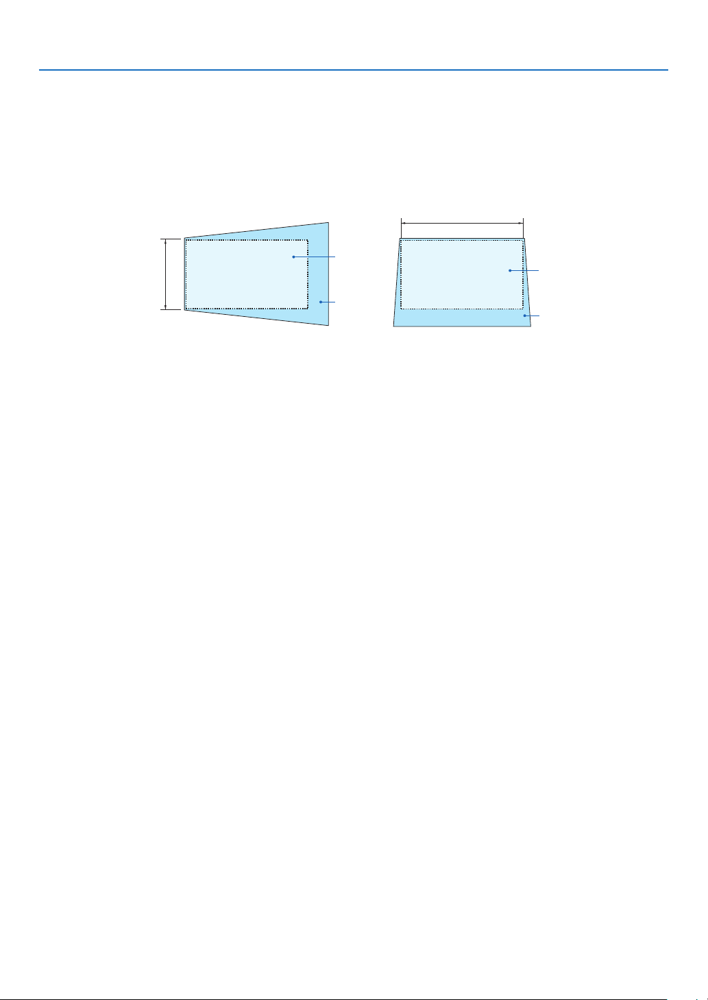
Note that all descriptions given in this manual assume that the angle of projection is zero degree. In case of projection
from an upper position or from the right or left, it is necessary to calculate the width for the minimum projected image
that is a little larger than the screen size.
Minimum width
Screen
Screen
Minimum
height
Projected
image
Projected
image
Projection from the left Projection from an upper position
6
1. Before Setting Up Your Projector
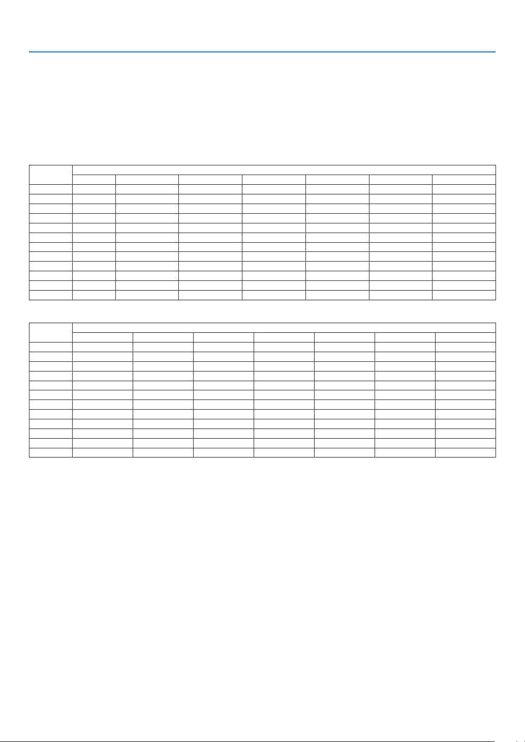
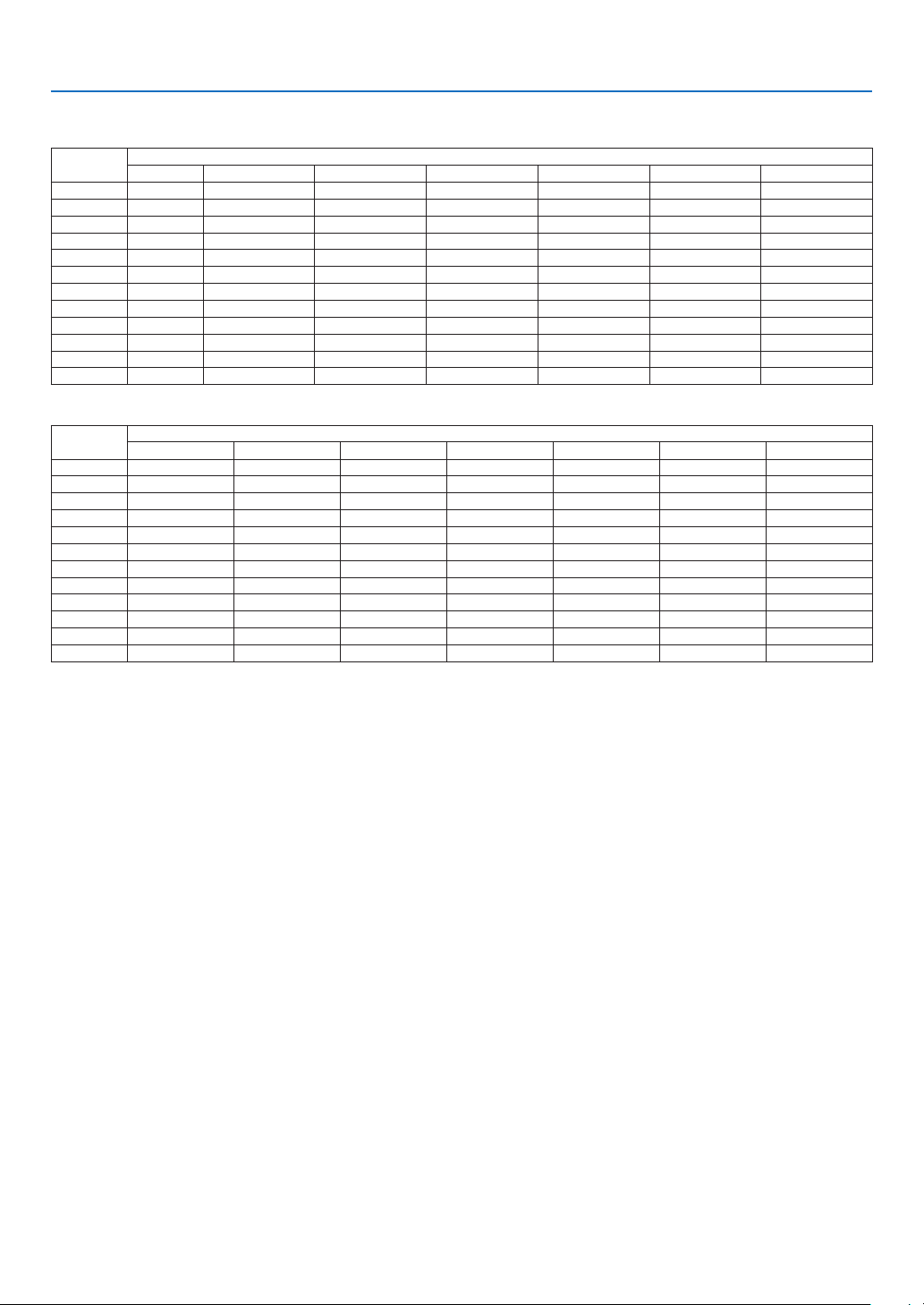
Throw distance and screen size
Seven separate bayonet style lenses can be used on this projector. Refer to the information on this page and use a
lens suited for the installation environment (screen size and throw distance). For installation and replacement of lens
units contact your distributor.
Each number provided in the table below means the throw distance between the lens surface and the screen.
Lens types and throw distance
4096 × 2160 (Aspect ratio: 17:9)
unit: inch
Screen
size
Lens model name
L2K-10F1 L4K-11ZML4K-15ZML4K-20ZML2K-30ZML2K-43ZM1L2K-55ZM1
100" 78.7 105.9–149.6131.2–181.1185.0–303.1232.3–338.6338.6–476.4433.1–677.2
120" 94.5128.0–181.1158.4–220.5216.5–362.2279.5–409.4405.5–574.8519.7–818.9
150" 122.0 161.2–224.4199.1–275.6271.7–448.8354.3–511.8511.8–720.5653.5–1027.6
200" 161.4 216.6–303.1267.0–370.1358.3–598.4476.4–689.0685.0–968.5874.0–1374.0
250" 204.7 271.9–378.0334.8–460.6444.9–744.1594.5–862.2858.3–1212.61098.4–1720.5
300" 244.1 327.2–456.7402.7–555.1531.5–889.8716.5–1035.41031.5–1456.71318.9–2070.9
350" 287.4 382.5–492.1470.5–649.6618.1–1039.4838.6–1212.61208.7–1704.71543.3–2417.3
400" 326.8 437.9–610.2538.4–744.1704.7–1185.0956.7–1385.81381.9–1948.81763.8–2763.8
500" 409.4548.5–763.8674.1–929.1878.0–1476.41200.8–1736.21728.3–2440.92208.7–3460.6
600" 492.1659.2–917.3809.8–1118.11051.2–1771.71440.9–2086.62078.7–2929.12653.5–4153.5
800" 657.5 880.5–1224.41081.2–1492.11397.6–2358.31925.2–2783.52775.6–3913.43543.3–5547.2
1000" 822.8 1101.8–1531.51352.6–1866.11744.1–2944.92409.4–3484.33468.5–4893.74433.1–6937.0
unit: m
Screen
size
Lens model name
L2K-10F1 L4K-11ZML4K-15ZML4K-20ZML2K-30ZML2K-43ZM1L2K-55ZM1
100" 2.0 2.7–3.83.3–4.64.7–7.75.9–8.68.6–12.111.0–17.2
120" 2.4 3.3–4.64.0–5.65.5–9.27.1–10.410.3–14.613.2–20.8
150" 3.1 4.1–5.75.1–7.06.9–11.49.0–13.013.0–18.316.6–26.1
200" 4.1 5.5–7.76.8–9.49.1–15.212.1–17.517.4–24.622.2–34.9
250" 5.2 6.9–9.68.5–11.711.3–18.915.1–21.921.8–30.827.9–43.7
300" 6.2 8.3–11.610.2–14.113.5–22.618.2–26.326.2–37.033.5–52.6
350" 7.3 9.7–12.512.0–16.515.7–26.421.3–30.830.7–43.339.2–61.4
400" 8.3 11.1–15.513.7–18.917.9–30.124.3–35.235.1–49.544.8–70.2
500" 10.4 13.9–19.417.1–23.622.3–37.530.5–44.143.9–62.056.1–87.9
600" 12.5 16.7–23.320.6–28.426.7–45.036.6–53.052.8–74.467.4–105.5
800" 16.7 22.4–31.127.5–37.935.5–59.948.9–70.770.5–99.490.0–140.9
1000" 20.928.0–38.934.4–47.444.3–74.861.2–88.588.1–124.3112.6–176.2
TIP
•Calculationofthethrowdistancefromthescreensize
L2K-10F1lensthrowdistance(m)=H×0.93:78.7"/2.0m(min.)to822.8"/20.9m(max.)
L4K-11ZMlensthrowdistance(m)=H×1.24toH×1.73:105.9"/2.7m(min.)to1531.5"/38.9m(max.)
L4K-15ZMlensthrowdistance(m)=H×1.52toH×2.10:131.2"/3.3m(min.)to1866.1"/47.4m(max.)
L4K-20ZMlensthrowdistance(m)=H×1.98toH×3.34:185.0"/4.7m(min.)to2944.9"/74.8m(max.)
L2K-30ZMlensthrowdistance(m)=H×2.71toH×3.92:232.3"/5.9m(min.)to3484.3"/88.5m(max.)
L2K-43ZM1lensthrowdistance(m)=H×3.91toH×5.52:338.6"/8.6m(min.)to4893.7"/124.3m(max.)
L2K-55ZM1lensthrowdistance(m)=H×4.99toH×7.82:433.1"/11.0m(min.)to6937.0"/176.2m(max.)
“H”(Horizontal)referstothescreenwidth.
*Figuresdifferbyseveral%withthetableabovebecausethecalculationisapproximate.
Ex.:Throwdistancewhenprojectingona300"screenusingtheL4K-15ZMlens:
Accordingtothe“Tablesofscreensizesanddimensions”incaseof4096×2160(AspectRatio17:9)(→page
9),H(screen
width)=265.4"/6.74m.
Thethrowdistanceis265.4"/6.74m×1.52to265.4"/6.74m×2.10=403.41"/10.24mto557.34"/14.15m(becauseofthezoom
lens).
7
1. Before Setting Up Your Projector
3840 × 2160 (Aspect ratio: 16:9)
unit: inch
Screen
size
Lens model name
L2K-10F1 L4K-11ZML4K-15ZML4K-20ZML2K-30ZML2K-43ZM1L2K-55ZM1
100" 82.7 111.5–157.5138.2–192.9192.9–318.9244.1–354.3354.3–500.0452.8–712.6
120" 102.4 134.9–189.0166.6–232.3228.3–381.9295.3–429.1429.1–602.4547.2–858.3
150" 126.0 169.8–240.2209.2–291.3283.5–472.4370.1–539.4535.4–759.8689.0–1078.7
200" 169.3228.0–318.9280.3–389.8374.0–629.9500.0–720.5720.5–1015.7921.3–1444.9
250" 212.6 286.3–401.6351.3–488.2464.6–783.5626.0–905.5901.6–1275.61153.5–1811.0
300" 255.9344.6–480.3422.3–586.6555.1–937.0752.0–1090.61086.6–1531.51385.8–2173.2
350" 299.2402.8–559.1493.3–685.0645.7–1090.6881.9–1271.71267.7–1791.31622.0–2539.4
400" 342.5 461.1–641.7564.4–783.5736.2–1248.01007.9–1456.71452.8–2047.21854.3–2905.5
500" 433.1 577.5–803.1706.4–976.4921.3–1555.11259.8–1822.81818.9–2563.02322.8–3637.8
600" 519.7694.1–964.6848.4–1173.21102.4–1862.21515.7–2192.92185.0–3078.72787.4–4366.1
800" 692.9927.1–1287.41132.5–1566.91464.6–2480.32023.6–2925.22917.3–4110.23724.4–5830.7
1000" 866.1 1160.0–1610.21416.6–1960.61830.7–3098.42531.5–3661.43645.7–5141.74657.5–7291.3
unit: m
Screen
size
Lens model name
L2K-10F1 L4K-11ZML4K-15ZML4K-20ZML2K-30ZML2K-43ZM1L2K-55ZM1
100" 2.1 2.8–4.03.5–4.94.9–8.16.2–9.09.0–12.711.5–18.1
120" 2.6 3.4–4.84.2–5.95.8–9.77.5–10.910.9–15.313.9–21.8
150" 3.2 4.3–6.15.3–7.47.2–12.09.4–13.713.6–19.317.5–27.4
200" 4.3 5.8–8.17.1–9.99.5–16.012.7–18.318.3–25.823.4–36.7
250" 5.4 7.3–10.28.9–12.411.8–19.915.9–23.022.9–32.429.3–46.0
300" 6.5 8.8–12.210.7–14.914.1–23.819.1–27.727.6–38.935.2–55.2
350" 7.6 10.2–14.212.5–17.416.4–27.722.4–32.332.2–45.541.2–64.5
400" 8.7 11.7–16.314.3–19.918.7–31.725.6–37.036.9–52.047.1–73.8
500" 11.0 14.7–20.417.9–24.823.4–39.532.0–46.346.2–65.159.0–92.4
600" 13.2 17.6–24.521.6–29.828.0–47.338.5–55.755.5–78.270.8–110.9
800" 17.6 23.5–32.728.8–39.837.2–63.051.4–74.374.1–104.494.6–148.1
1000" 22.0 29.5–40.936.0–49.846.5–78.764.3–93.092.6–130.6118.3–185.2
TIP
•Calculationofthethrowdistancefromthescreensize
L2K-10F1lensthrowdistance(m)=H×0.99:82.7"/2.1m(min.)to866.1"/22.0m(max.)
L4K-11ZMlensthrowdistance(m)=H×1.33toH×1.84:111.5"/2.8m(min.)to1610.2"/40.9m(max.)
L4K-15ZMlensthrowdistance(m)=H×1.62toH×2.24:138.2"/3.5m(min.)to1960.6"/49.8m(max.)
L4K-20ZMlensthrowdistance(m)=H×2.11toH×3.57:192.9"/4.9m(min.)to3098.4"/78.7m(max.)
L2K-30ZMlensthrowdistance(m)=H×2.89toH×4.19:244.1"/6.2m(min.)to3661.4"/93.0m(max.)
L2K-43ZM1lensthrowdistance(m)=H×4.17toH×5.88:354.3"/9.0m(min.)to5141.7"/130.6m(max.)
L2K-55ZM1lensthrowdistance(m)=H×5.33toH×8.34:452.8"/11.5m(min.)to7291.3"/185.2m(max.)
“H”(Horizontal)referstothescreenwidth.
*Figuresdifferbyseveral%withthetableabovebecausethecalculationisapproximate.
Ex.:Throwdistancewhenprojectingona300"screenusingtheL4K-15ZMlens:
Accordingtothe“Tablesofscreensizesanddimensions”incaseof3840×2160(AspectRatio16:9)(→page
9),H(screen
width)=261.5"/6.64m.
Thethrowdistanceis261.5"/6.64m×1.62to261.5"/6.64m×2.24=423.63"/10.76mto585.76"/14.87m(becauseofthezoom
lens).
8
1. Before Setting Up Your Projector
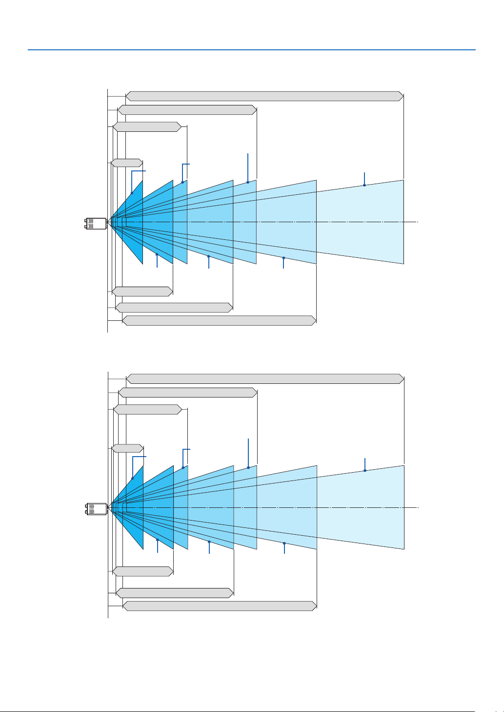
Projection range for the different lenses
4096 × 2160 (Aspect ratio: 17:9)
L2K-55ZM1 433.1–6937.0"/11.0–176.2 m
L2K-43ZM1 338.6–4893.7"/8.6–124.3 m
L2K-30ZM 232.3–338.6"/5.9–88.5 m
L4K-20ZM 185.0–2944.9"/4.7–74.8 m
L4K-11ZM
105.9–1531.5"/
2.7–38.9 m
L4K-15ZM
131.2–1866.1"/
3.3–47.4 m
L2K-10F1
78.7–822.8"/
2.0–20.9 m
100–1000"100–1000"100–1000"
100–1000"
100–1000"
100–1000"
100–1000"
3840 × 2160 (Aspect ratio: 16:9)
L2K-55ZM1 452.8–7291.3"/11.5–185.2 m
L2K-43ZM1 354.3–5141.7"/9.0–130.6 m
L2K-30ZM 244.1–3661.4"/6.2–93.0 m
L4K-20ZM 192.9–3098.4"/4.9–78.7 m
L4K-11ZM
111.5–1610.2"/
2.8–40.9 m
L4K-15ZM
138.2–1960.6"/
3.5–49.8 m
L2K-10F1
82.7–866.1"/
2.1–22.0 m
100–1000"100–1000"100–1000"
100–1000"
100–1000"
100–1000"
100–1000"
9
1. Before Setting Up Your Projector
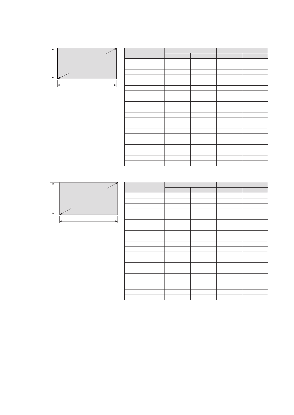
Tables of screen sizes and dimensions
4096 × 2160 (Aspect ratio: 17:9)
Screen height
Screen width
17:9 screen size
(diagonal)
Size (inches) Screen width Screen height
(inches) (cm) (inches) (cm)
100 88.5 224.7 46.6 118.5
120 106.1 269.656.0 142.2
150 132.7 337.0 70.0 177.7
200 176.9449.393.3237.0
250 221.1 561.7 116.6 296.2
300 265.4 674.0 139.9355.4
350 309.6786.4 163.3 414.7
400 353.8 898.7186.6 473.9
450 398.01011.0 209.9533.2
500 442.3 1123.4 233.2 592.4
550 486.5 1235.7 256.6 651.6
600 530.7 1348.0 279.9710.9
650 575.0 1460.4 303.2 770.1
700 619.21572.7 326.5 829.4
750 663.4 1685.1 349.8888.6
800 707.6 1797.4373.2 947.8
850 751.91909.7396.51007.1
900796.12022.1 419.81066.3
950840.3 2134.4 443.1 1125.6
1000 884.5 2246.7 466.5 1184.8
3840 × 2160 (Aspect ratio: 16:9)
Screen height
Screen width
16:9 screen size
(diagonal)
Size (inches) Screen width Screen height
(inches) (cm) (inches) (cm)
100 87.2 221.4 49.0124.5
120 104.6 265.7 58.8 149.4
150 130.7 332.1 73.5 186.8
200 174.3 442.8 98.1249.1
250 217.9553.5 122.6 311.3
300 261.5 664.1 147.1 373.6
350 305.1 774.8 171.6 435.8
400 348.6 885.5 196.1498.1
450 392.2996.2220.6 560.4
500 435.8 1106.9245.1 622.6
550 479.41217.6 269.6684.9
600 522.91328.3 294.2747.2
650 566.5 1439.0318.7 809.4
700 610.1 1549.7343.2 871.7
750 653.7 1660.4 367.7 933.9
800 697.31771.0 392.2996.2
850 740.8 1881.7 416.7 1058.5
900784.4 1992.4441.2 1120.7
950828.0 2103.1 465.7 1183.0
1000 871.6 2213.8 490.31245.3
10
1. Before Setting Up Your Projector
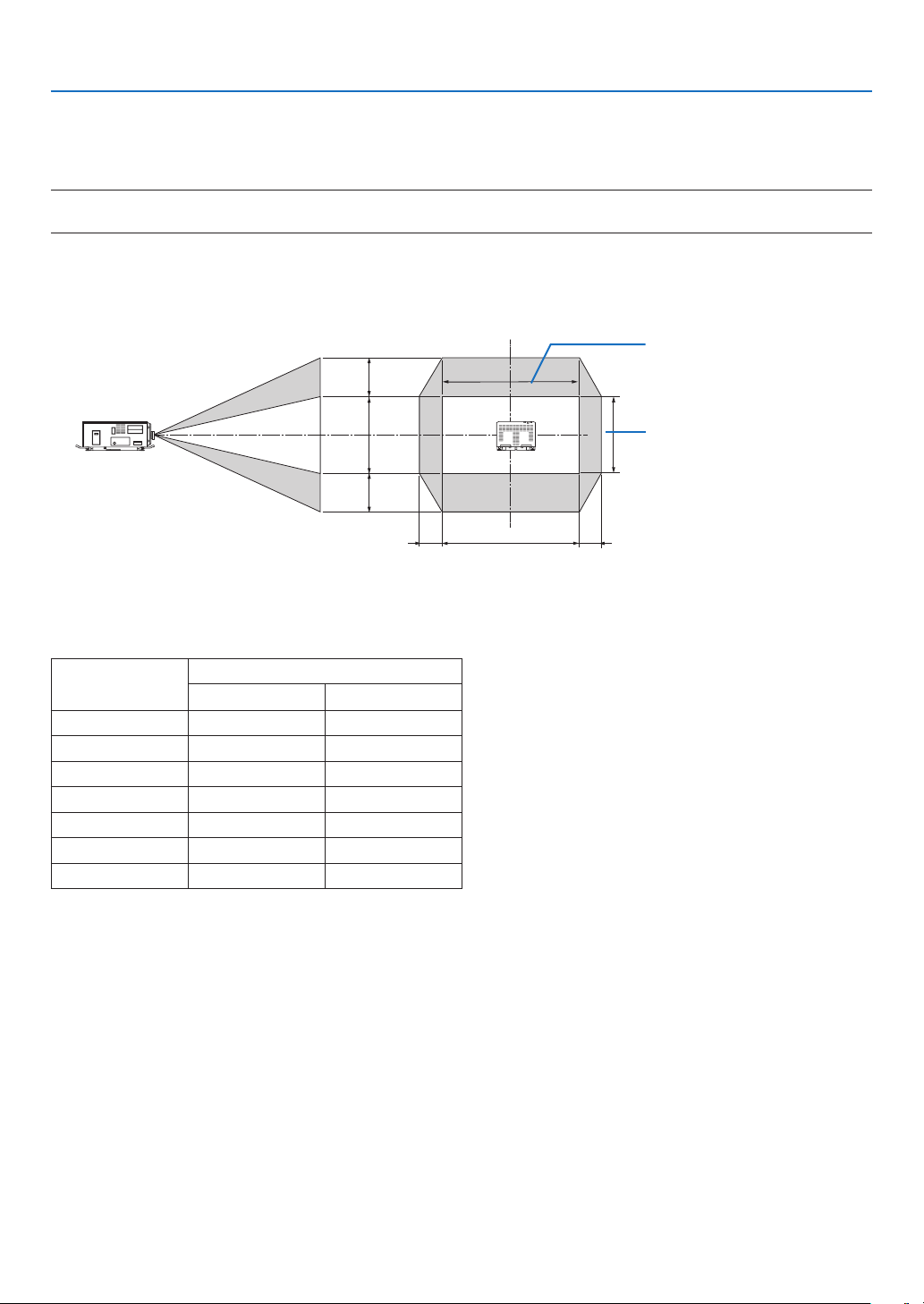
Lens shifting range
This projector is equipped with a lens shift function for adjusting the position of the projected image by using the LENS
SHIFT buttons (→ page
77). The lens can be shifted within the range shown below.
NOTE:
•Pleasedonotusethelensshiftfunctionwhenprojectingportraitimages.Pleaseuseitwiththelensinthecenter.
Legend: V “Vertical” refers to the screen height and H “Horizontal” refers to the screen width. The lens shift range is
expressed as a ratio of height and width, respectively.
100%V
③
④
100%H
①②
Height of projected image
Width of projected image
* The lens shift range is the same for ceiling installation.
4096 × 2160 (Aspect ratio: 17:9)
Lens unit Drawing number
①② ③④
L2K-10F1 8%H 27%V
L4K-11ZM17%H 50%V
L4K-15ZM17%H 50%V
L4K-20ZM17%H 50%V
L2K-30ZM8%H 27%V
L2K-43ZM18%H 27%V
L2K-55ZM110%H 31%V
(Examplecalculation)Ifprojectingona300inchscreenusinganL4K-15ZMlensunit
According to the “Table of screen sizes and dimensions” (→ page
9),H=265.4"/674.0cm,V=139.9"/355.4cm.
Adjustmentrangeintheverticaldirection:theprojectedimagecanbemovedupwards0.5×139.9"/355.4cm≈
70"/178 cm, downwards approximately 70"/178 cm (when the lens is at the center position). Adjustment range in the
horizontal direction: the projected image can be moved to the left 0.17 × 265.4"/674.0 cm ≈ 45"/115 cm, to the right
approximately 45"/115 cm.
* Figures differ by several % because the calculation is approximate.

11
1. Before Setting Up Your Projector
3840 × 2160 (Aspect ratio: 16:9)
Lens unit Drawing number
①② ③④
L2K-10F1 12%H 34%V
L4K-11ZM22%H 55%V
L4K-15ZM22%H 55%V
L4K-20ZM22%H 55%V
L2K-30ZM12%H 34%V
L2K-43ZM112%H 34%V
L2K-55ZM114%H 37%V
(Examplecalculation)Ifprojectingona300inchscreenusinganL4K-15ZMlensunit
According to the “Table of screen sizes and dimensions” (→ page
9), H = 261.5"/664.1 cm, V = 147.1"/373.6 cm.
Adjustment range in the vertical direction: the projected image can be moved upwards 0.55 × 147.1"/373.6 cm ≈
81"/205 cm, downwards approximately 81"/205 cm (when the lens is at the center position). Adjustment range in the
horizontal direction: the projected image can be moved to the left 0.22 × 261.5"/664.1 cm ≈ 58"/146 cm, to the right
approximately 58"/146 cm.
* Figures differ by several % because the calculation is approximate.
12
1. Before Setting Up Your Projector
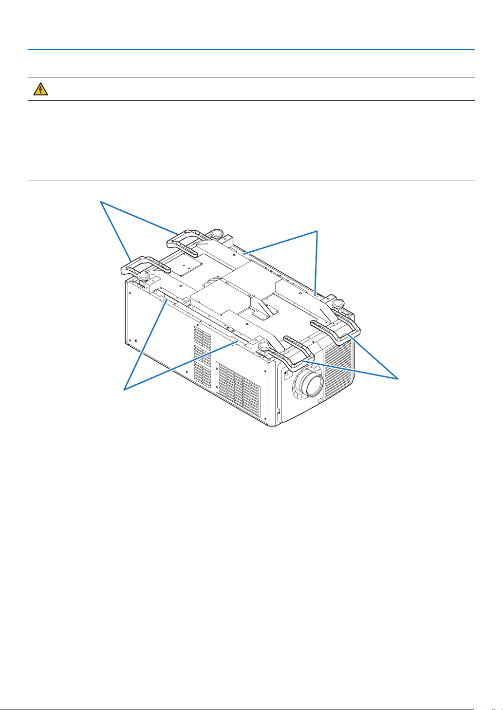
1-4. Carrying the projector
WARNING
•Whenmovingtheprojector,itshouldbecarriedbyholdingthehandlesorhookonthebaseoftheunitby6or
more people.
•Whenmovingtheprojector,rstturnoffthepowerandalwaysdisconnectthepowerplugfromtheelectrical
outlet, and check that all of the connecting cables between equipment and the lenses have been removed.
•ForC1connection,turnofftheprojector,shutdownACpowerbyusingacircuitbreaker.
•ForC2connection,turnofftheprojector,shutdowntheACpowertotheprojectorandthelightusingacircuit
breaker.
Handles
Handles
Hook
Hook
13
1. Before Setting Up Your Projector
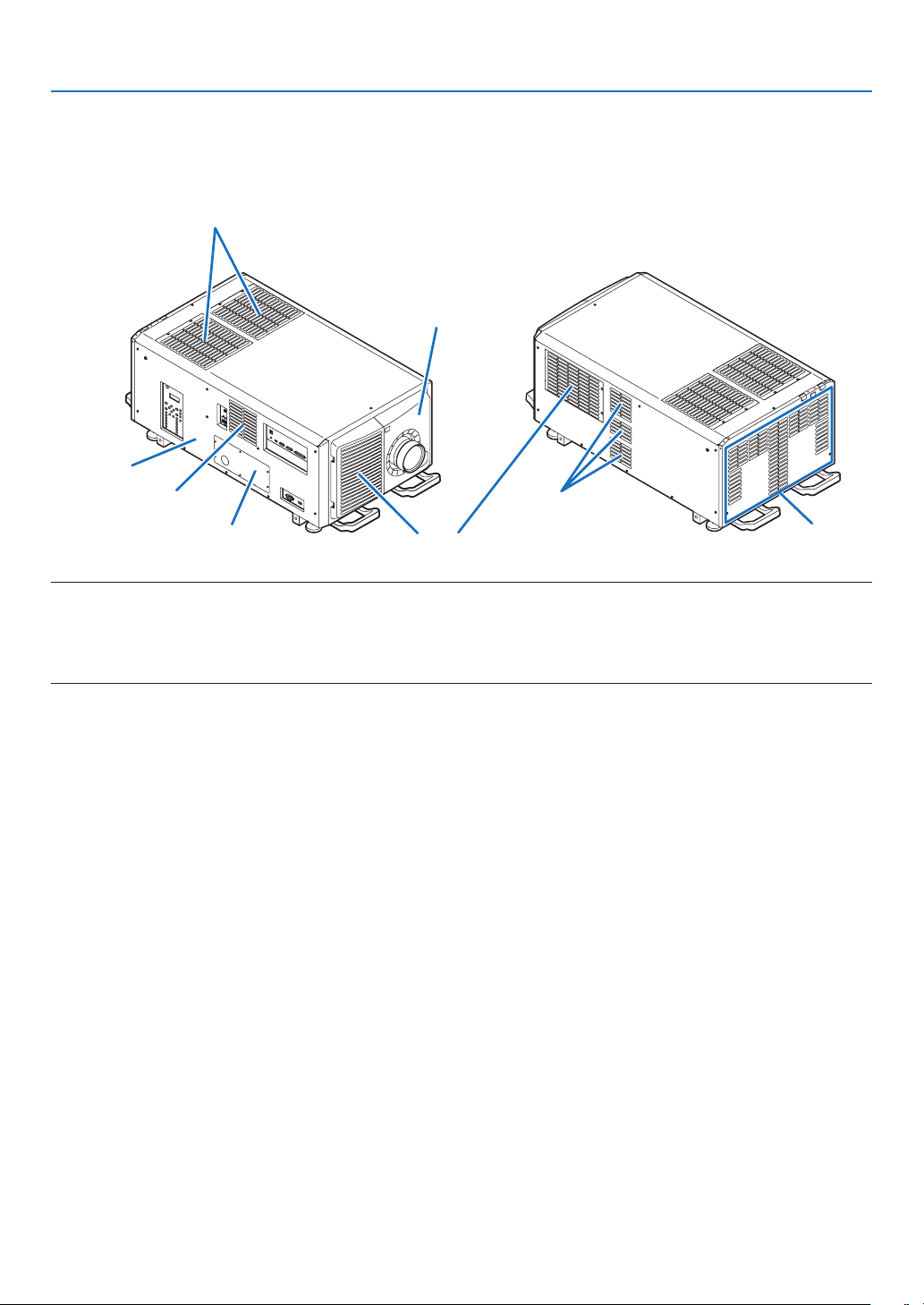
1-5. Removing and Mounting the Projector Covers
This section provides guideline information on how to remove and mount covers on the projector.
Name of the cover
Plate inlet
Air inlet (Filter cover / Filter)
Lens cover
Side panel
Air outlet
Air outlet
Air outlet
Air inlet (Filter cover / Filter)
NOTE:
•“Sidepanel”and“Lenscover”areequippedwithkeylocks.Specialkeys(servicekey)arerequiredtoremoveormountthem.
Referto“Positionofthekeylocksonthecovers”(→page14)fordetails.
•Donotturnonthepowerwhenthelenscoverandthesidepanelareremoved.
•Whenremovingthelenscover,returnthelensshifttothecenterpositionbeforeturningoffthepower.
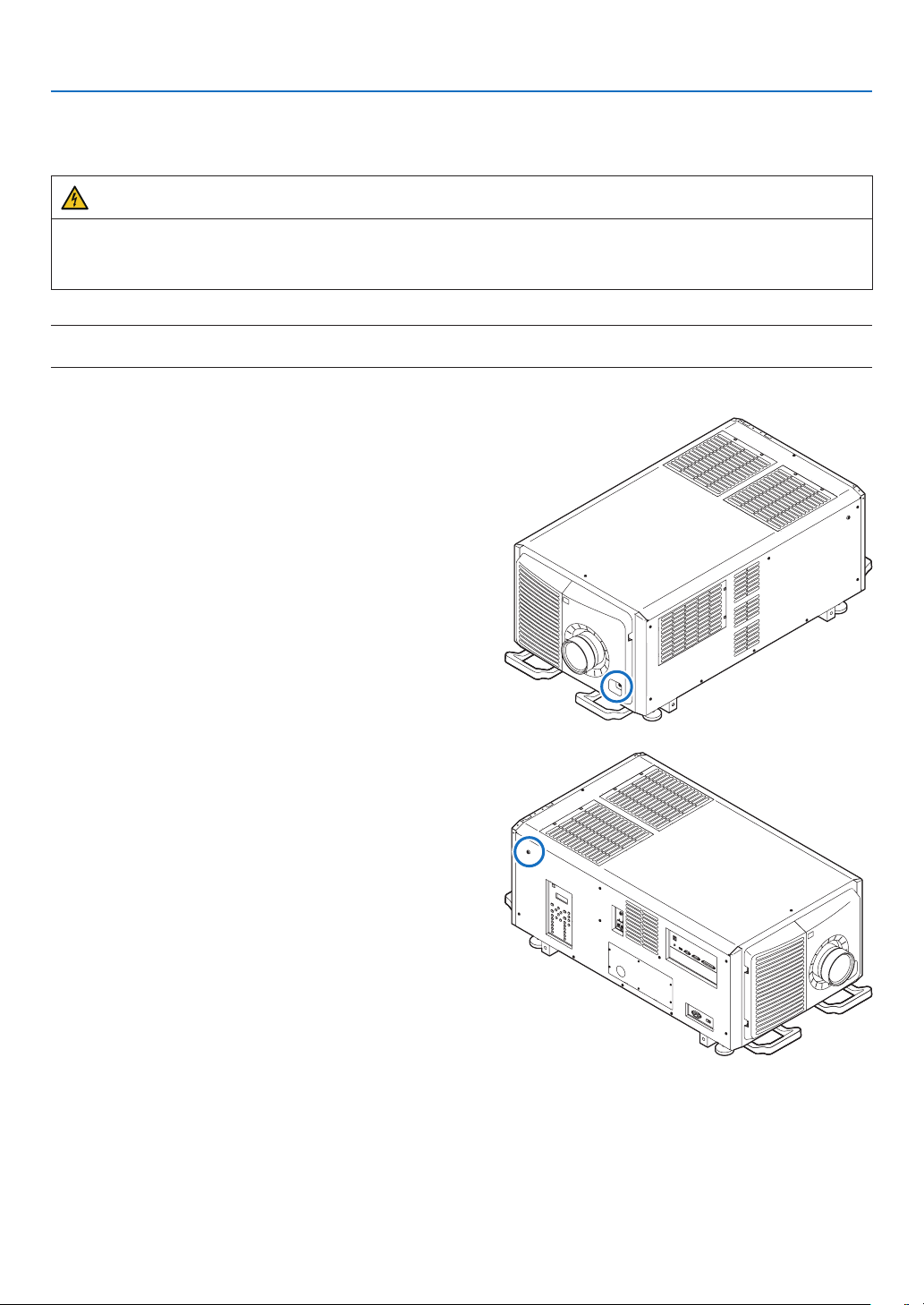
14
1. Before Setting Up Your Projector
Position of the key locks on the covers
When removing or attaching a cover of the projector main unit, the lock needs to be unlocked using the included
service key. The positions of the locks on each of the covers are as follows.
WARNING
TOREDUCETHERISKOFELECTRICSHOCKANDLASERRADIATION,DONOTOPENCOVER.NOUSER-
SERVICEABLEPARTSINSIDE.REFERSERVICINGANDINSTALLATIONTOQUALIFIEDSERVICEPERSON-
NELANDINSTALLATIONPERSONNEL.
NOTE:
•Whenacoverisremoved,thepowertotheunitisautomaticallyturnedoffbythesafetyprotectionsystem.
Lens Cover
The lock is unlocked when attaching or removing lenses
(→ page
64).
Side Panel
The lock is unlocked when Installing the LV unit (→ page
59).
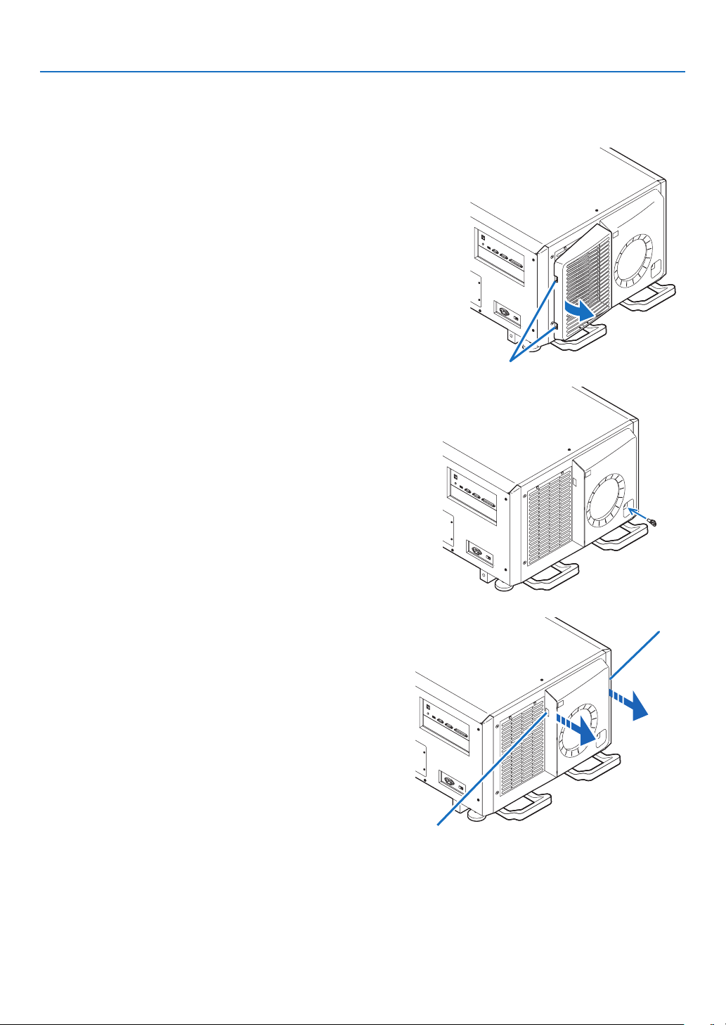
15
1. Before Setting Up Your Projector
1-5-1. Removing and Mounting the Lens Cover
Preparation:
Service key (attached goods)
1. Remove the front filter cover.
Pull the filter cover in the direction of the arrow to remove it.
Handle
2. Unlock the lens cover.
Unlock the cover using the service key.
3. Remove the lens cover.
The lens cover is secured to the projector body by two claws
each at the cover top and bottom.
Hold the cover sides and pull toward you.
Handle
Handle
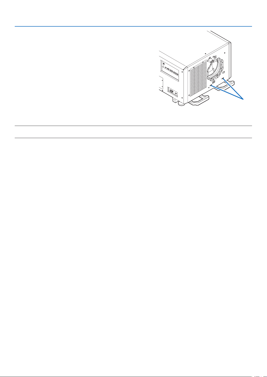
16
1. Before Setting Up Your Projector
•Thiscompletesremovingthelenscover.Tomountthecover,
perform the removal procedure in reverse. Make sure to
lock the key.
Hook
* Lens cover removed condition
NOTE:
•Ifthecoverisnotproperlymounted,anerrormayoccur.Securelypushallclawsintotheposition.
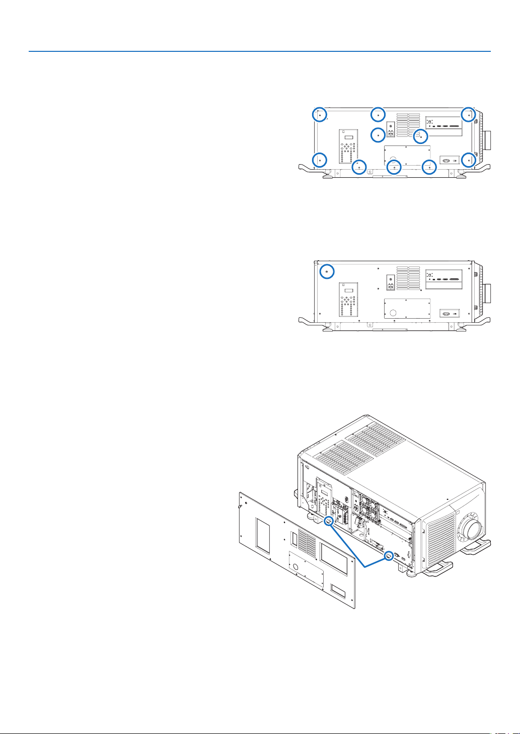
17
1. Before Setting Up Your Projector
1-5-2. Removing and Mounting the Side Panel
Preparation:
Phillips-head screwdriver (No.2), service key (attached goods)
1. Loosen the ten fixing screws on the side panel.
Loosen four screws on the side panel until they
are free to spin. The screws do not detach from
the panel.
2. Unlock the side panel.
Unlock the cover using the service key.
3. Remove the side panel.
The side panel is fixed in place by hooks at the
bottom (in 2 locations). Tilt the side panel toward
you and pull up to remove it. Do not use force
when tilting the side panel.
Hook
(2 locations)
This completes removing the side panel. To mount the side panel, perform the removal procedure in reverse. Make
sure that you do not forget to tighten the screws or to lock the key lock.
1-5-3. Removing and Mounting the Filter Cover
Refer to "6-3-1. Cleaning the Air Filter" (→ page 94) for details on how to remove and attach the lter cover.

18
1. Before Setting Up Your Projector
1-6. Selecting the Power Cable for C2 Connection (English)
The power cable for C2 Connection is not included with the projector. Refer to “AC Power Work Specications” (
next
page) and provide the necessary power cable.
WARNING
Carefully read the contents described in this section before connection and connect the cables according to the
proper procedure. Inappropriate handling may cause fatal, serious or other bodily injuries due to re or electric shock.
CAUTION
•Beforeconnectingthepowercables,checkthatthemainpowerswitchoftheprojectoristurnedoff.Implement
the connection with AC power shut off.
•Besuretogroundtheequipmenttoensuresafety.Useapowercablethatmeetsthestandardsandpowersup-
ply voltage of the country where you are using the projector (→ page
19), and always connect the equipment to
the ground. If the ground is not connected, it may cause electrical shocks.
•WhenconnectingthepowercableplugstotheACINandtheelectricaloutlet,securelyinserttheplugsalltheway
in. If the connection between the power cable plug and the electrical outlet is loose, the plug area may generate
heat, causing burns and accidents.
•Inordertopreventthepowerplugfrombeingdisconnectedfromtheprojector,xthepowercablebyusingthe
power cable stopper supplied with this unit. For how to use the power cable stopper, refer to “Attaching the
power cable stopper” (→ page 36)
NOTE:
•InstalltheelectricoutletnearbytheprojectormainunitsothatthepowersupplycanbecutbyunpluggingtheACpowercable.
•WhenplugginginorunpluggingtheACpowercable,makesurethatthemainpowerswitchispushedtothe[O]position.Failure
todosomaycausedamagetotheprojector.
•Donotuseathree-phasepowersupply.Doingsomaycausemalfunction.
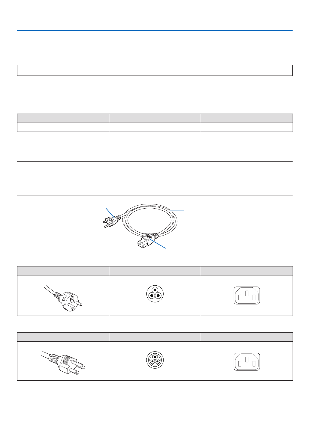
19
1. Before Setting Up Your Projector
AC Power Work Specications
AC power supply equipment
Do not use any voltage other than those shown below for the AC power supply connected to the projector.
200–240VAC,singlephase,power,50/60Hz
AC power supply cable for the projector
The projector is equipped with an IEC60320-C14 inlet to connect an AC power supply cable. Use an IEC60320-C13
compliant AC power cable connector and ensure that the connector meets the following current capacity specications.
Power supply voltage Projector input current Power cable current capacity
AC200–240V4.9A10A or higher
Furthermore, use plugs, cables, and connectors that are suitable for the regulations of the country of installation, as
shown in the following table.
NOTE:
•ForusersinNorthAmerica
Useapowercablenolongerthan4.5m/14.76ftaccordingtoNationalElectricalCode.
•ForUKonly:InUK,aBSapprovedpowercablewithmouldedplughasablack(10Amps)fuseinstalledforusewiththisequip-
ment.Ifapowercableisnotsuppliedwiththisequipment,pleasecontactyoursupplier.
Cable
Plug
Connector
Germany
Plug Cable Connector
CEE 7
H05VV-F 3 x 1 mm
2
IEC60320 C13
USA
Plug Cable Connector
NEMA 6-15P
SJT 3 x AWG 16 IEC60320 C13
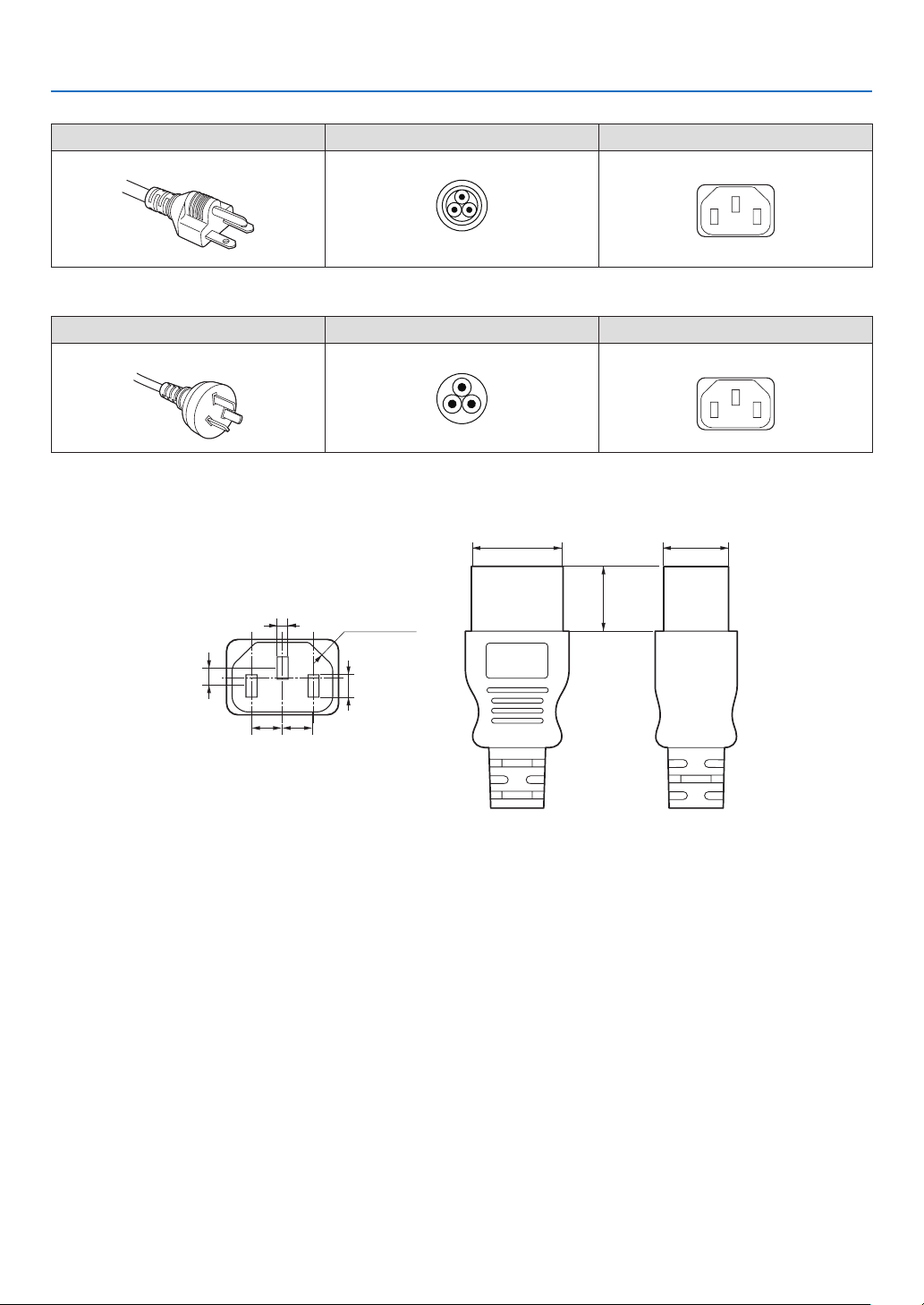
20
1. Before Setting Up Your Projector
Japan
Plug Cable Connector
JIS C 8303
HVCTF 3 x 1.25 mm
2
IEC60320 C13
China
Plug Cable Connector
GB2099
RVV 300/500 GB17465.1
Connector
Dimensions of the connector of the power cable are shown below.
28
+0
-
0.9
20
+0
-
0.7
5
+ 0.5
-
0
4
+ 0.5
-
0
2.5
+ 0.5
-
0
4-R3.5
20
7
+0.5
-
0
7
+0.5
-
0
Unit: mm
(Min)
(Min)

21
1. Before Setting Up Your Projector
1-7. Auswahl des Netzkabels für Anschluss C2 (Deutsch)
Es wird kein Netzkabel für Anschluss C2 mit dem Projektor geliefert. Nehmen Sie auf „Netzstrom-Spezikationen“
(
Nächste Seite) Bezug, und beschaffen Sie das notwendige Netzkabel.
WARNUNG
Lesen Sie diesen Abschnitt vor dem Herstellen der Verbindungen sorgfältig durch, und schließen Sie die Kabel
anhand der ordnungsgemäßen Verfahren an. Falsche Handhabung kann zu schweren oder sogar tödlichen Ver-
letzungen durch Brand oder einen elektrischen Schlag führen.
ACHTUNG
•BevorSiedasNetzkabelanschließen,prüfenSie,obdieHauptstromschalterdesProjektorsausgeschaltetist.
Stellen Sie die Verbindungen bei ausgeschaltetem Netzstrom her.
•ErdenSiedasGerät,umdieSicherheitzugewährleisten.VerwendenSieeinNetzkabel,dasdieNormenund
Netzspannung des Landes, in dem der Projektor verwendet wird, erfüllt (→ Seite
22), und schließen Sie das
Gerät stets an Erde an. Wenn keine Erde angeschlossen wird, kann es zu elektrischen Schlägen kommen.
•FührenSiedieNetzkabelsteckerbeimAnschließenbiszumAnschlagindenNetzeingangunddieNetzsteckdose
ein. Sitzt der Netzstecker nicht fest in der Netzsteckdose, kann Wärme im Steckerbereich erzeugt werden, die
zu Verbrennungen und Unfällen führen kann.
•UmeineTrennungdesNetzsteckersvomProjektorzuverhindern,xierenSiedasNetzkabel,indemSieden
mit diesem Gerät gelieferten Netzkabelstopper verwenden. Die Verwendung des Netzkabelstoppers siehe 50.
HINWEIS:
•InstallierenSiedieSteckdosenahebeimProjektor,sodassSiedieStromzufuhrunterbrechenkonnen,indemSiedasNetzkabel
abtrennen.
•VergewissernSiesich,dassderHauptstromschalteraufderPosition[O]steht,bevorSiedasNetzkabelanschliesenoderabziehen.
AnderenfallskanneszueinerBeschadigungdesProjektorskommen.
•VerwendenSiekeineDreiphasen-Stromversorgung.AnderenfallskanneszueinerFunktionsstorungkommen.
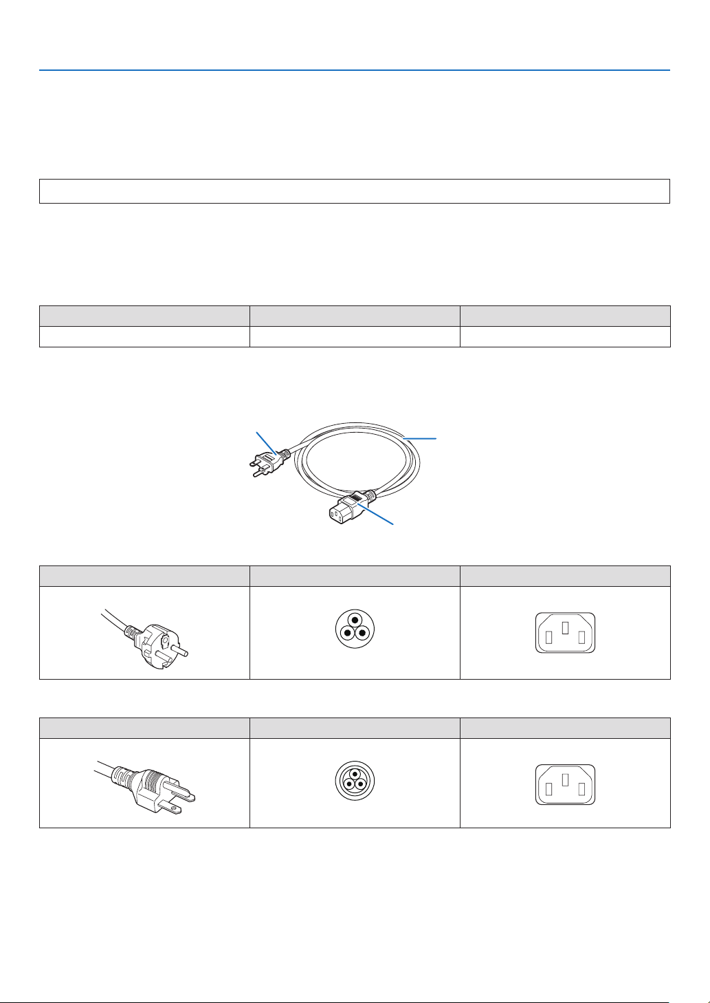
22
1. Before Setting Up Your Projector
Netzstrom-Spezikationen
Netzkabel
DerProjektoristmiteinemC19-SteckverbindergemäßIEC60320zumAnschließendesNetzkabelsausgestattet.
Sorgen Sie dafür, dass die Netzkabel, die von den Steckverbindern am Projektor zum Netzanschluss führen, über
die unten angegebenen Stromkapazitäten verfügen.
200–240VAC,eiphasig,50/60Hz
Netzkabel für den Projektor
Der Projektor ist mit einem C14-Eingang gemäß IEC60320 zum Anschließen des Netzkabels ausgestattet.Verwenden
Sie einen IEC60320 C13-kompatiblen Netzkabelanschluss und sorgen Sie dafür, dass der Anschluss über die unten
angegebene Stromkapazität verfügt.
Netzspannung Projektor-Eingangsstrom Netzkabel-Stromkapazität
200–240VWechselstrom4,9A10 A oder höher
Verwenden Sie zudem Stecker, Kabel und Steckverbinder, die den Vorgaben des jeweiligen Landes entsprechen
(siehe dazu folgende Tabelle).
Kabel
Stecker
Steckverbinder
Deutschland
Stecker Kabel Steckverbinder
CEE 7
H05VV-F 3 x 1 mm
2
IEC60320 C13
USA
Stecker Kabel Steckverbinder
NEMA 6-15P
SJT 3 x AWG 16 IEC60320 C13
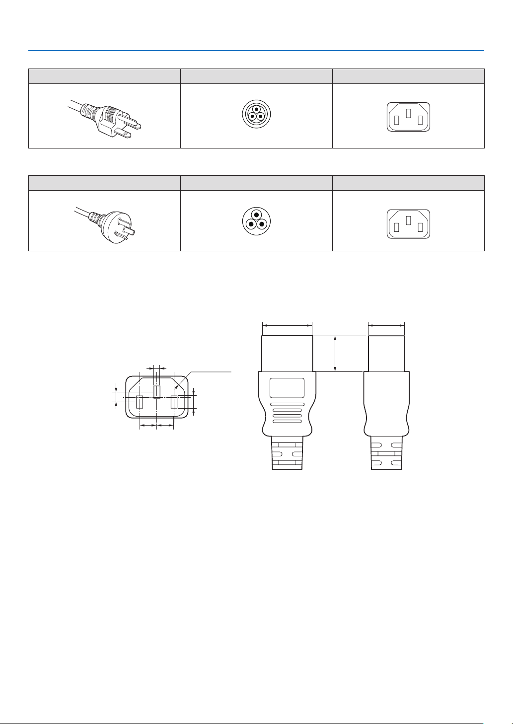
23
1. Before Setting Up Your Projector
Japan
Stecker Kabel Steckverbinder
JIS C 8303
HVCTF 3 x 1.25 mm
2
IEC60320 C13
China
Stecker Kabel Steckverbinder
GB2099
RVV 300/500 GB17465.1
Für Benutzer in UK
VerwendenSieeinNetzteilmitBS-Zulassungund10A-Sicherung.
Steckverbinder
Die Abmessungen des Netzkabels sind unten angegeben.
28
+0
-
0.9
20
+0
-
0.7
5
+ 0.5
-
0
4
+ 0.5
-
0
2.5
+ 0.5
-
0
4-R3.5
20
7
+0.5
-
0
7
+0.5
-
0
Einheit: mm
(Min)
(Min)
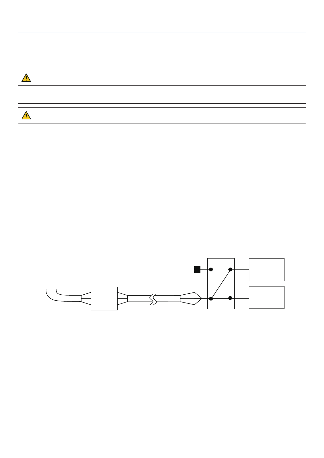
24
1. Before Setting Up Your Projector
1-8. Connecting the power cable (English)
Connect the power cable of the projector. The AC power cable is not attached as an accessory. Be sure to have
professional technicians do any power supply construction.
WARNING
Carefully read the contents described in this section before connection and connect the cables according to the
proper procedure. Inappropriate handling may cause fatal, serious or other bodily injuries due to re or electric shock.
CAUTION
•MakesurethattheACpowersupplyisdisconnectedbeforecarryingouttheworkofconnectingthepowersupply
cable.
•Besuretofollowthecontentsdescribedinthissection.
•Entrustaspecialisttocarryoutthepowersupplyworkfromthepowersupplyequipmentofthebuildingtothe
place of projector installation.
•Besuretogroundtheequipmenttoensuresafety.Toavoidelectricshock,requestaprofessionaltocarryout
the grounding and related works. Make sure to ground the equipment before supply of the AC power.
1-8-1. Power supply construction specifications
There are two different ways to connect the power cables, the C1 connection and the C2 connection.
• C1 connection
AC power is provided to the projector power supply and the light power supply by a single cable.
AC power supply cable
Input Selection
C1 connection
Projector
(Main unit)
Light power
supply unit
AC power supply
equipment
Breaker
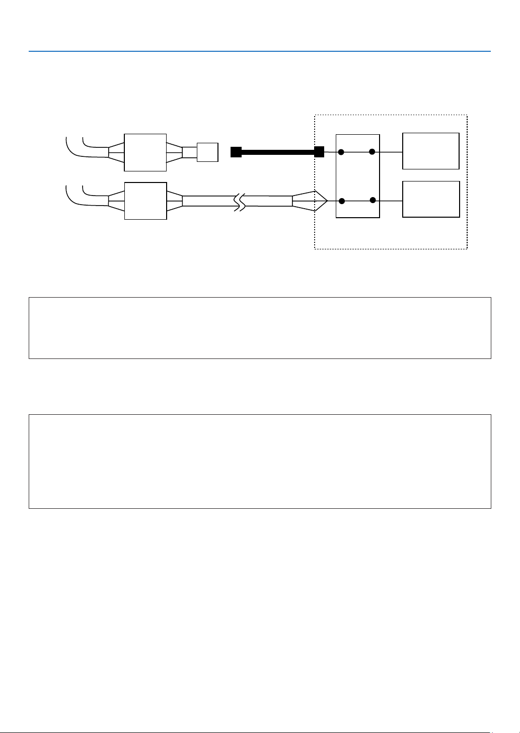
25
1. Before Setting Up Your Projector
• C2 connection
AC power is provided to the projector power supply and the light power supply by separate cables.
AC power supply cable
AC power supply
cable
Electric outlet
Input Selection
C2 connection
Projector
(Main unit)
Light power
supply unit
AC power supply
equipment
AC power supply
equipment
Breaker
Breaker
AC power supply equipment
Do not connect AC power supply voltages to the projector other than those indicated below.
When using with a C1 connection
•200-240VAC,singlephase,50/60Hz
When using with a C2 connection
•200-240VAC,singlephase,50/60Hz(projectorpowersupply)
•200-240VAC,singlephase,50/60Hz(lightpowersupply)
Breakers
When connecting the AC power supply from the power supply equipment of the building to the projector, be sure to
connect it through a breaker. The capacity of the breaker must be as indicated below.
When using with a C1 connection
•Powersupplyforprojector+powersupplyforlight
200V-240 V AC: Input current 40A, Inrush current 150A or higher @10msec
When using with a C2 connection
•Powersupplyforprojector
200V-240 V AC: Input current 10A, Inrush current 60A or higher @10msec
•Powersupplyforlight
200V-240 V AC: Input current 40A, Inrush current 150A or higher @10msec
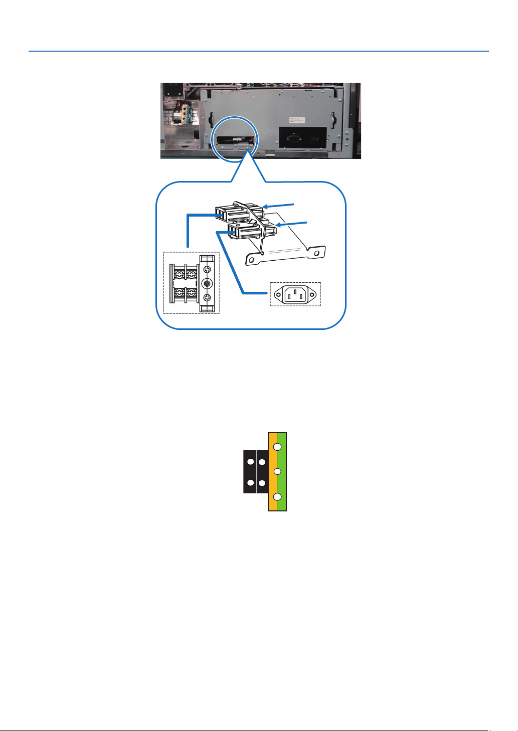
26
1. Before Setting Up Your Projector
Input Selection
The power supply connection method is congured by the wiring to the input selection. The congurations are as follows.
C1 Connection
C2
Connection
AC power supply cable
•FortheACpowercable,useacableofthicknessasappropriatefortheinstallationcountryandmadeofcopperas
shown below.
•UsearoundtypeUL-listedsolderlessterminalforthesectionconnectedtothemainunit.Inaddition,whenclamping
this terminal with the cable, use an UL listed tool.
Compatible Cables and Solderless Terminals
The specications of the terminals for attaching the power cables are as follows.
Power supply terminal L, N Grounding terminal G
The size of the solderless terminal to use and the fastening torque of the screws varies depending on the type of
terminal block. Use the cable and solderless terminal that is suitable for the specic type of terminal block as shown
in the following table. This species the model name of the recommended solderless terminals. Use these parts or
equivalent parts. If you are unable to use the recommended solderless terminals, ensure that you use terminals of
the dimensions shown in the following diagram.
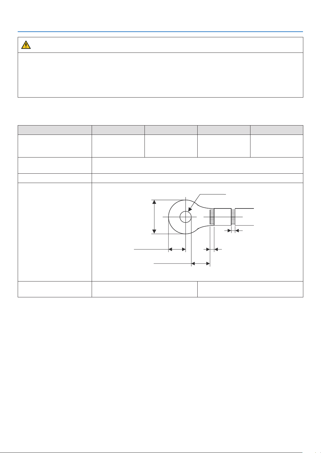
27
1. Before Setting Up Your Projector
WARNING
•Thepowersupplyunithandleslargeelectricalcurrents.Tomaintainsafety,usewireswiththespecicationsas
shown in the following table, and affix to the terminals at the designated attachment torque.
•Alwaysusesolderlessterminalswiththedimensionsasshowninthefollowingdiagram.
•TheuseofpartswithdimensionsotherthanasdesignatedcreatesariskoftheACpowersupplyunitshort
circuiting due to the terminal block generating heat and melting because the terminal block of the light power
supply unit cannot be attached correctly.
• Power supply terminal L, N (Black)
AC power is provided to the projector power supply and the light power supply by a single cable.
JIS IEC/EN UL CSA
Thickness of compatible
wiring (using solderless ter-
minal)
14 mm
2
14 mm
2
AWG6 or
AWG8
AWG6 or
AWG8
Solderless terminal dimen-
sions
M5 x 10
Tightening torque 2.0 to 2.5N·m
Solderless terminal dimen-
sions
Min 1.0
Min 1.0
-Max 2.0
-Max 2.0
Max 5.8
Min ⌀6.1
Max 12.2
Min 4.5
Unit: mm
Solderless terminal recom-
mended part (J.S.T parts)
Model R8-5 When using AWG6: Model R14-5
When using AWG8: Model R8-5
J.S.T: J.S.T. Manufacturing Co. Ltd.

28
1. Before Setting Up Your Projector
• Ground terminal G (Green/Yellow)
JIS IEC/EN UL CSA
Thickness of compatible
wiring (using solderless ter-
minal)
14 mm
2
14 mm
2
AWG6 or
AWG8
AWG6 or
AWG8
Solderless terminal dimen-
sions
M6 x 15
Tightening torque 3.5 to 5.0N·m
Solderless terminal dimen-
sions
Min 1.0
Min 1.0
-Max 2.0
-Max 2.0
Max 11
Min ⌀6.1
Max 13
Min 7.5
Unit: mm
Solderless terminal recom-
mended part (J.S.T parts)
Model 8-8NS When using AWG6: Model R14-6
When using AWG8: Model 8-8NS
J.S.T: J.S.T. Manufacturing Co. Ltd.

29
1. Before Setting Up Your Projector
Connecting the cable
In order to attach the power cable to the connector block, connect the wires using the following procedure such that
the individual wires cannot directly touch each other.
1. Remove the power cable sleeves from the terminals to
ensure that the sleeves are not pinched by the terminal
attachment screw.
Pull back the sleeves from the terminal area before fastening
the screw to prevent the sleeves from being pinched.
Sleeves
2. Attach the sleeves after tightening the screw.
Tighten the fixing screw to the designated torque.
Use sleeves and secure the insulation to ensure that terminals
do not touch each other. If the cables are attached to the
powersupplyterminalwithoutusingsleeves,thereisariskof
the terminals touching each other as shown in the photograph
on the right.

30
1. Before Setting Up Your Projector
When connecting the cables to the ground terminal block, ensure
that parts other than the solderless terminal (such as cable wires
and ttings) are not pinched within the terminal fastening area.
When correctly fastened.
When the cable wire has become pinched due to using a solderless
terminal with dimensions other than as designated.
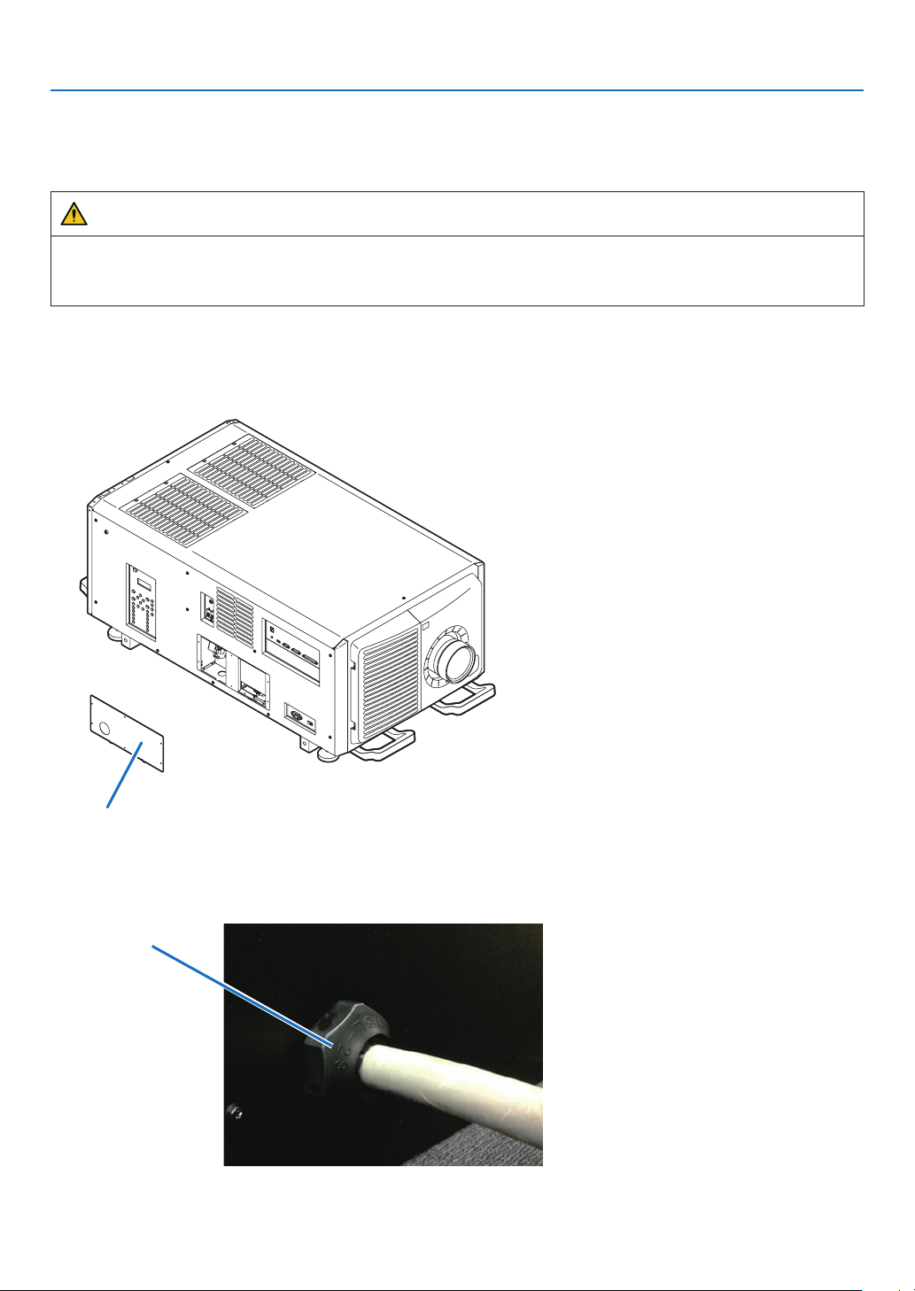
31
1. Before Setting Up Your Projector
1-8-2. Procedure for connecting the power cable (C1 connection)
Preparation:
Phillips-head screwdriver (No. 2), service key (projector accessory)
WARNING
•Beforeconnectingthepowercable,makesurethattheACpowersupplyisdisconnected.Otherwiseareor
electric shock may occur.
•Highleakagecurrentows.DoNOTconnectthepowersupplybeforegroundingconnection.
1. Remove the plate inlet.
Remove the plate inlet by loosening the fixing screws (at six points).
InEurope,replaceitwiththesupplied⌀35 plate inlet.
Plate Inlet
2. Pass the power cable through the cable hole of the plate.
If you use the supplied ⌀35plateinlet,passthepowercablethroughacommerciallyavailablecablestopper
and then insert it into the cable hole.
Cable stopper
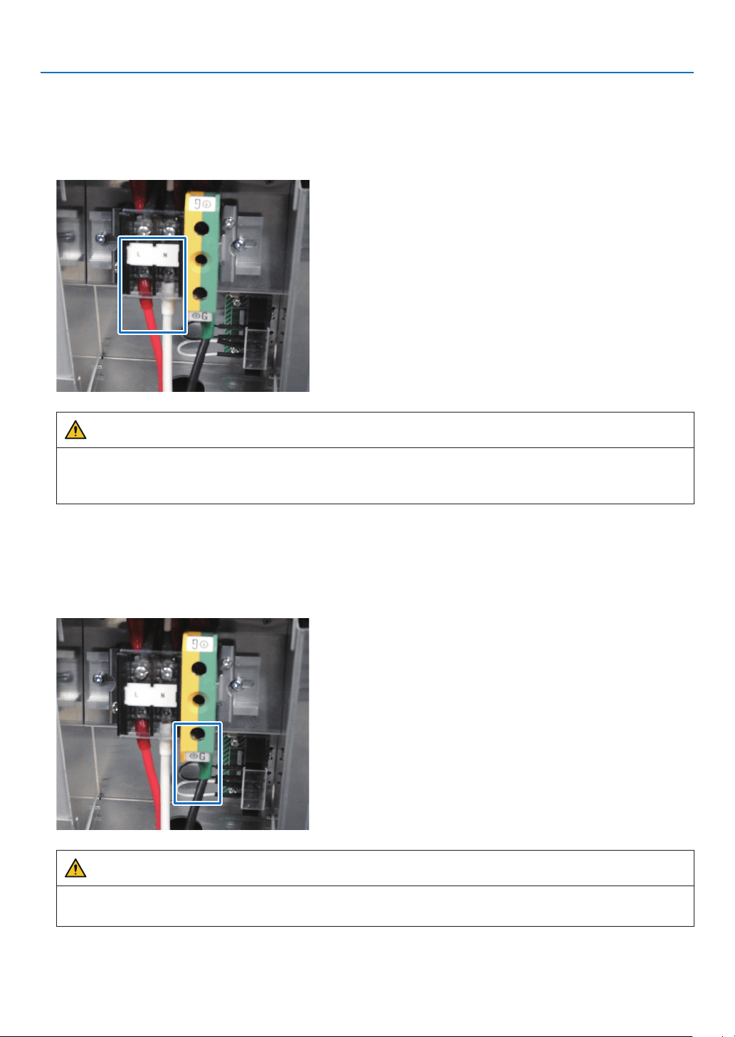
32
1. Before Setting Up Your Projector
3. Remove the terminal cover of the power supply terminals.
Remove the terminal cover by pulling it upward.
4. Insert the L/N lines of the AC power cable into the connection terminals, and tighten the screws.
InsertthecrimpingterminalsoftheACpowercableintotheretainingholesoftheconnectionterminals,andtighten
the screws with the Phillips-head screwdriver.
WARNING
Securely screw the AC power cable to the connection terminals. Also, after tightening the screws, make sure
that all the power cable lines are securely screwed. A failure to do this could result in an accident causing death,
injury, etc.
5. Put the terminal cover on the power supply terminals.
Follow the reverse procedure to removal of the terminal cover.
6. Insert the grounding cable into the grounding terminal, and screw it.
Insertthecrimpingterminalofthegroundingcableintotheretainingholeoftheconnectionterminal,andtighten
the screw with the Phillips-head screwdriver.
WARNING
Securely screw the grounding cable to the connection terminal. Also, after tightening the screw, make sure that
the screw is securely tightened. A failure to do this could result in an accident causing death, injury, etc.

33
1. Before Setting Up Your Projector
7. Remove the fixing screws (at two points), eject the fixing bracket in the direction of the arrow, and pull out
the power connector.
8. Configure the power supply for C1 connection.
ForC1connection,connecttheinner-sideconnector.
Connect
Connect
9. Return the power connector and the fixing bracket to their original position, and fix the fixing screws (at
two points).
10
. Fix the plate inlet with the fixing screws (at six points).
InEurope,fixthesupplied⌀35 plate inlet.
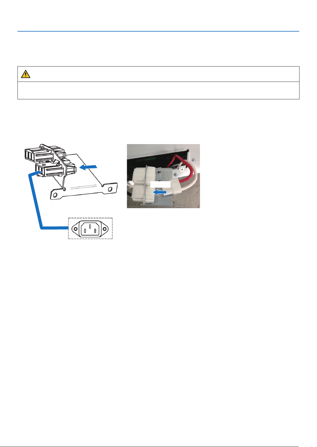
34
1. Before Setting Up Your Projector
1-8-3. Procedure for connecting the power cable (C2 connection)
Preparation:
Phillips-head screwdriver (No. 2), service key (projector accessory)
WARNING
Beforeconnectingthepowercable,makesurethattheACpowersupplyisdisconnected.Otherwiseareor
electric shock may occur.
1. Follow steps to in “1-8-2. Procedure for connecting the power cable (C1 connection)” (page
31).
2. Configure the power supply for C2 connection.
ForC2connection,connecttheouter-sideconnector.
Connect
Connect
3. Return the power connector and the fixing bracket to their original position, and fix the fixing screws (at
two points).
4. Fix the plate inlet with the fixing screws (at six points).

35
1. Before Setting Up Your Projector
5. Connect the AC power supply cable.
(1) Connect the AC power supply cable.
Connect the AC power supply cable to the projector.
To wall outlet
AC input
(2) Connect the power plug to the electrical outlet.
This completes the connection of the AC power supply
cable.
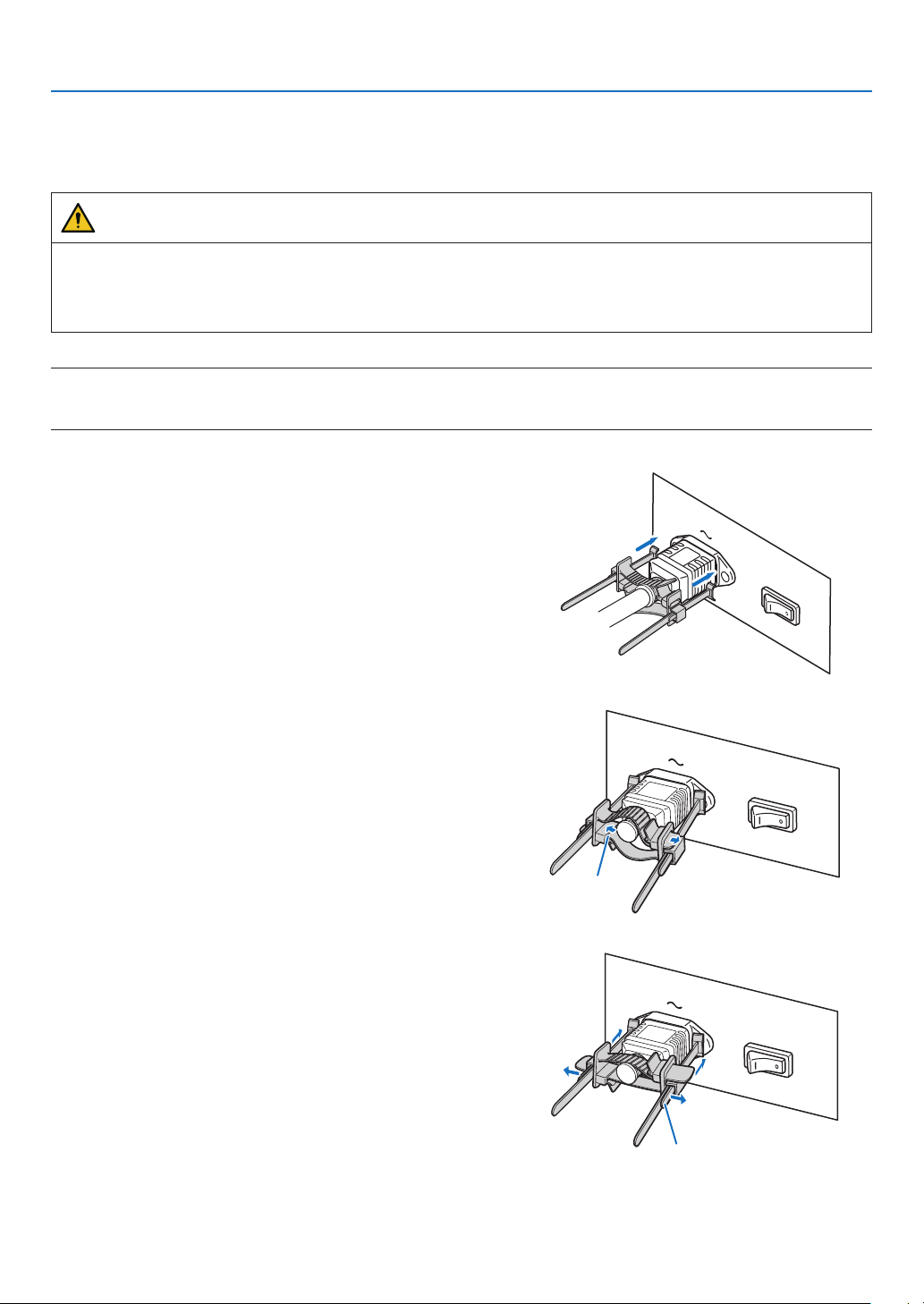
36
1. Before Setting Up Your Projector
Attaching the power cable stopper
To prevent the power cable from accidently removing from the AC IN of the projector, attach the supplied power cable
stopper to clamp the power cable.
CAUTION
•To prevent the power cable from coming loose, make sure that all the prongs of the power cable are fully inserted
into the AC IN terminal of the projector before using the power cable stopper to x the power cable. A loose
contact of the power cable may cause a re or electric shock.
•Do not bundle the power cable. Doing this could cause heat or a re.
NOTE
•
Donotclampthepowercablewithothercables.Doingsocangeneratenoise,whichcanaffectadverselythesignalcable.
•Becarefulnottoinsertthebandinversely.Oncethebandisattached,itcannotberemovedfromtheslot.
1. Set the clamper band to the power cable side, and
insert the end of band of the power cable stopper into
the slot next to the AC IN on the terminal panel.
Attach the power cable stopper to the other side in the
same way.
2. Pass each band through the slits in the power cable
stopper.
Pass the bands through them so that the power cable will
be sandwiched from above and below.
Band
3. Slide the clamper to the hilt of the power cable.
Pulling the knob in the arrow direction allows you to adjust
the clamper position.
Once the clamper position is adjusted,releasetheknob
to lock the clamper.
Knob
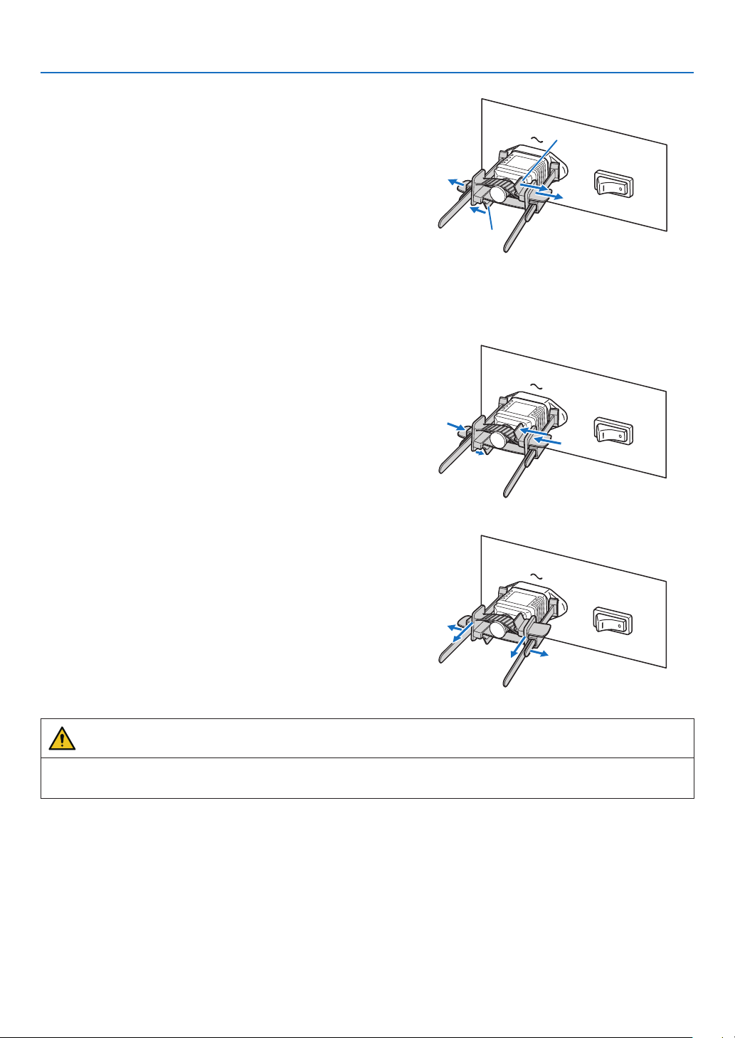
37
1. Before Setting Up Your Projector
4. Pull the band to hold the power cable.
Pulling the knob in the arrow direction allows you to adjust
the band position.
Pull the top and bottom bands by keeping their balance.
Once the band position is adjusted,releasetheknob to
lock.
Knob
Knob
This completes the attachment of the power cable stopper.
Removing the power cable from the power cable stopper
1. Pull the knob of the clamper and loosen the band.
2. Pull the knob and slide the clamper away from the
power plug.
CAUTION
•The projector may become hot temporarily when the power is turned off or if the AC power is disconnected while
the projector is projecting. Take care when handling the projector.
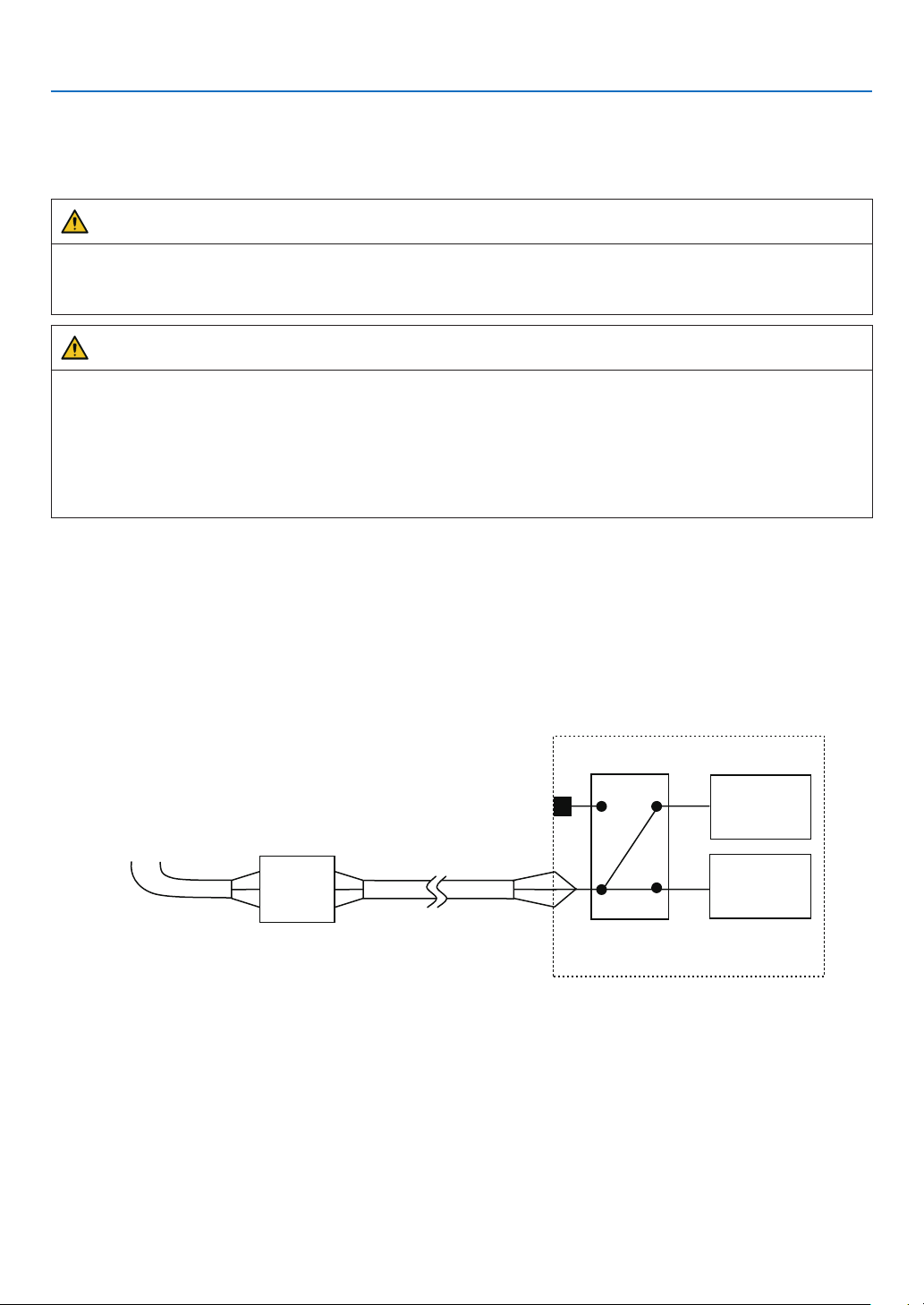
38
1. Before Setting Up Your Projector
1-9. Anschließen des Netzkabels (Deutsch)
Schließen Sie das Netzkabel des Projektors an. Das Netzkabel ist nicht abziehbar sondern fest mit dem Gerät verbun-
den. Lassen Sie die Installation einer Netzstromversorgung unbedingt nur von professionellen Elektrikern durchführen.
WARNUNG
Lesen Sie diesen Abschnitt sorgfältig durch, bevor Sie die Kabel anschließen, und befolgen Sie beim Anschließen
der Kabel die entsprechenden Anweisungen. Durch unsachgemäße Handhabung kann es infolge von Bränden
oder elektrischen Schlägen zu tödlichen, schweren oder anderen Verletzungen kommen.
ACHTUNG
•VergewissernSiesich,dassdasGerätvonderStromversorgunggetrenntist,bevorSiedasNetzkabelanschließen.
•BefolgenSieaufjedenFalldieAnweisungenindiesemAbschnitt.
•BeauftragenSieeinenFachmannmitderInstallationdieStromzufuhrvonderStromversorgungsanlagedes
Gebäudes zum Aufstellort des Projektors.
•ErdenSiedasGerät,umdieSicherheitzugewährleisten.UmelektrischeSchlägezuvermeidenbeauftragen
Sie einen Fachmann mit der Erdung und den damit verbundenen Arbeiten. Stellen Sie sicher, dass das Gerät
geerdet ist, bevor Sie Strom zuführen.
1-9-1. Technische Daten zum Netzanschluss
Die Netzkabel können auf zweierlei Weise angeschlossen werden: zum einen über Anschluss C1 und zum anderen
über Anschluss C2.
• Anschluss C1
Die Stromversorgung zu den Netzteilen des Projektors und der Lichtquelle wird über ein einzelnes Kabel zugeführt.
Netzstromkabel
Eingabe Auswahl
Anschluss C1
Projektor
(Grundgerät)
Licht Netzteil
Netzstrom-
versorgung
Sicherung
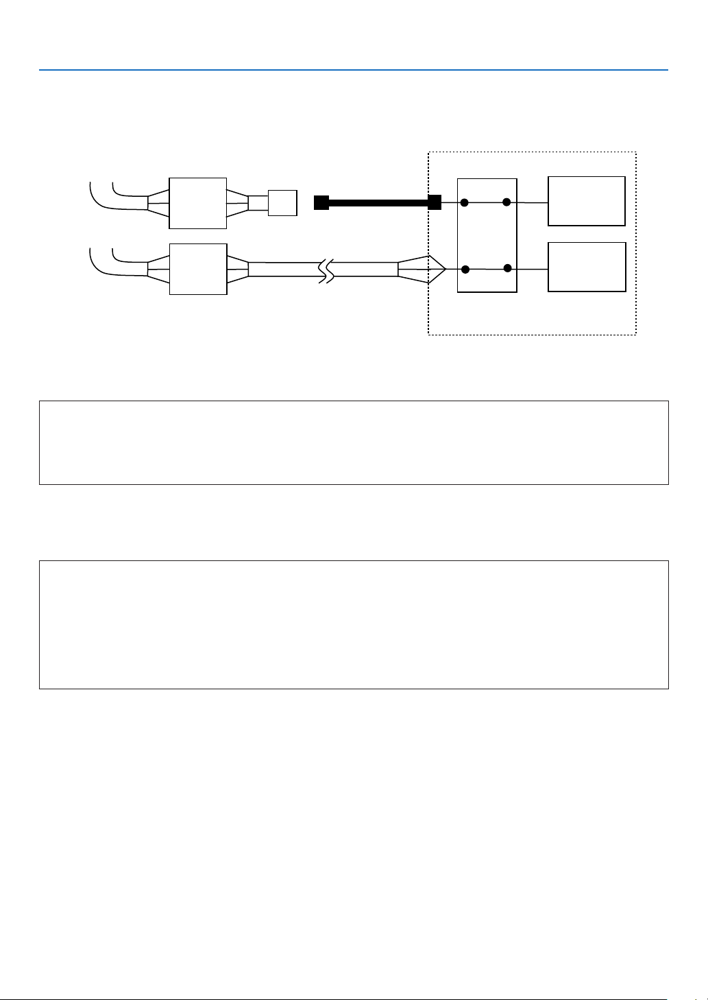
39
1. Before Setting Up Your Projector
• Anschluss C2
Die Stromversorgung zu den Netzteilen des Projektors und der Lichtquelle wird über getrennte Kabel zugeführt.
Netzstromkabel
Netzstromkabel
Elektrosteckdos
Eingabe Auswahl
Anschluss C2
Projektor
(Grundgerät)
Licht Netzteil
Netzstrom-
versorgung
Netzstrom-
versorgung
Sicherung
Sicherung
Wechselstromversorgung
Betreiben Sie den Projektor nur mit den unten angegebenen Netzspannungen.
Bei Verwendung von Anschluss C1
•200–240VAC,einphasig,50/60Hz
Bei Verwendung von Anschluss C2
•200–240VAC,einphasig,50/60Hz(StromversorgungdesProjektors)
•200–240VAC,einphasig,50/60Hz(StromversorgungderLichtquelle)
Sicherungen
Stellen Sie beim Anschließen der Stromversorgungsanlage des Gebäudes an den Projektor sicher, dass dies über
eine Sicherung erfolgt. Der maximale Kennwert der Sicherung muss den folgenden Angaben entsprechen.
Bei Verwendung von Anschluss C1
•StromversorgungdesProjektors+StromversorgungderLichtquelle
200V-240 V AC: Eingangsstrom 40A, Einschaltstrom 150A oder höher @10msec
Bei Verwendung von Anschluss C2
•StromversorgungdesProjektors
200V-240 V AC: Eingangsstrom 10A, Einschaltstrom 60A oder höher @10msec
•StromversorgungderLichtquelle
200V-240 V AC: Eingangsstrom 40A, Einschaltstrom 150A oder höher @10msec
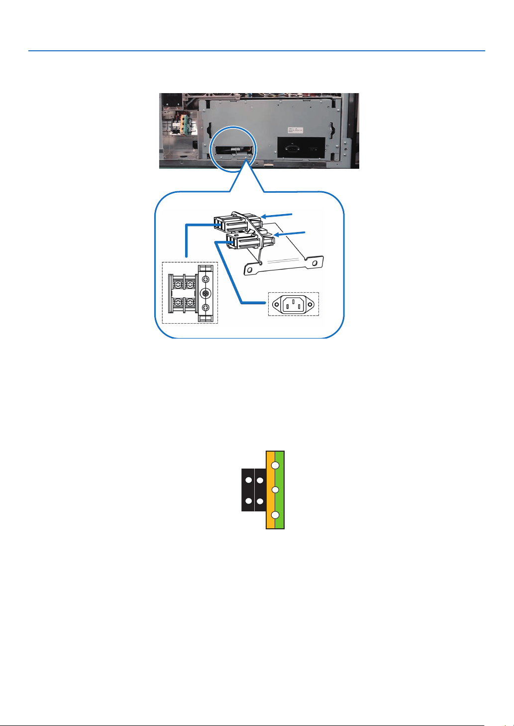
40
1. Before Setting Up Your Projector
Eingabe Auswahl
Die Netzanschluss Methode wird durch die Schaltung der Eingabe Auswahl festgelegt. Die Kongurationsmöglich-
keiten sind im Folgenden aufgeführt.
Anschluss C1
Anschluss
C2
Netzkabel
•VerwendenSiealsNetzkabeleinKabelmiteinerKabeladerausKupferundeinemLeiterquerschnitt,derdenVor-
gaben des jeweiligen Landes entspricht (siehe folgende Abbildung).
•VerwendenSieeinerundelötfreieAnschlussklemmemitdemULListing-PrüfzeichenfürdenanderHaupteinheit
angeschlossenen Kabelabschnitt. Verwenden Sie darüber hinaus bei der Klemmung dieser Anschlussklemme ein
Werkzeug mit dem UL Listing-Prüfzeichen.
Kompatible Kabel und lötfreie Anschlussklemmen
Die technischen Daten für die Anschlussklemmen zum Befestigen der Netzkabel sind im Folgenden aufgeführt.
Netzklemme L, N Erdklemme G
Die Größe der zu verwendenden lötfreien Anschlussklemme und das Anzugsmoment der Schrauben hängen von der
Art des Klemmenblocks ab. Verwenden Sie das Kabel und die lötfreie Anschlussklemme, die jeweils für den entsprech-
enden Klemmenblock geeignet sind (siehe folgende Tabelle). In dieser Tabelle sind die Modellnamen der empfohlenen
lötfreien Anschlussklemmen angegeben. Verwenden Sie die angegebenen oder gleichwertige Bauteile. Wenn Sie die
empfohlenen lötfreien Anschlussklemmen nicht verwenden können, stellen Sie sicher, dass Sie Anschlussklemmen
verwenden, deren Abmessungen den Angaben in der folgenden Tabelle entsprechen.
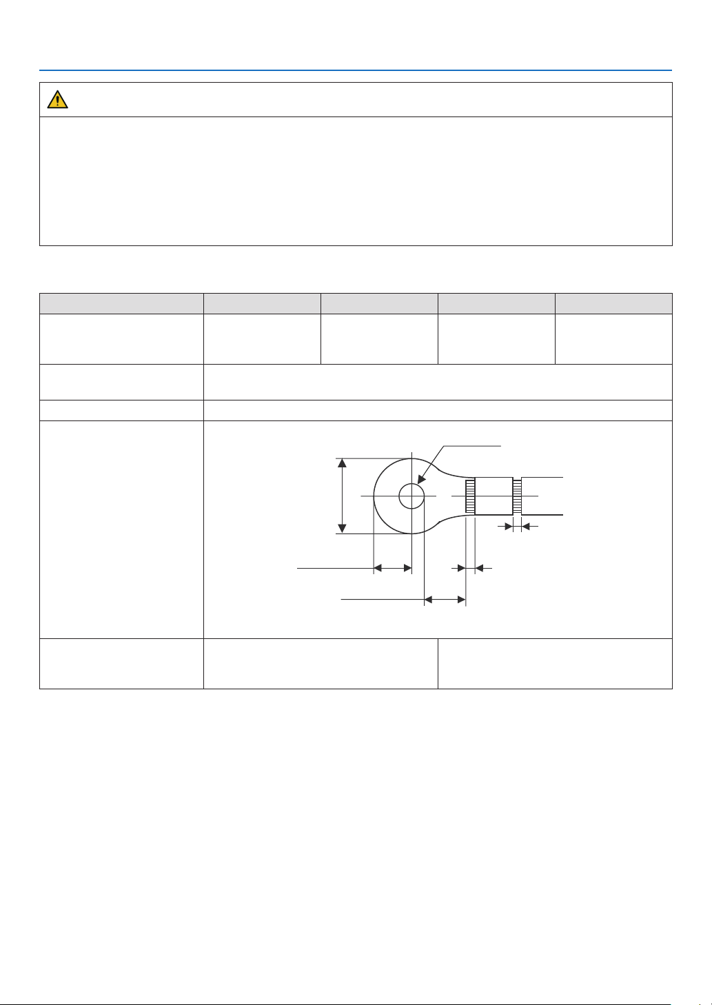
41
1. Before Setting Up Your Projector
WARNUNG
•DasNetzteilverarbeitethoheelektrischeStröme.VerwendenSiezurGewährleistungderSicherheitKabeladern
entsprechend den in der folgenden Tabelle aufgeführten Vorgaben, und befestigen Sie die Anschlussklemmen
am angegebenen Klemmenblock.
•VerwendenSieimmerlötfreieAnschlussklemmen,derenAbmessungendenAngabeninderfolgendenAbbildung
entsprechen.
•DieVerwendungvonBauteilenmitabweichendenAbmessungenbirgtdieGefahreinesKurzschlussesdes
Netzteils aufgrund von Hitzeentwicklung und Schmelzen des Klemmenblocks, da der Klemmenblock für die
Stromversorgung der Lichtquelle nicht ordnungsgemäß angebracht werden kann.
• Netzklemme L, N (Schwarz)
JIS IEC/EN UL CSA
Leiterquerschnitt kompati-
bler Kabel (bei Verwendung
lötfreier Anschlussklemmen)
14 mm
2
14 mm
2
AWG6 oder
AWG8
AWG6 oder
AWG8
Abmessungen lötfreier An-
schlussklemmen
M5 x 10
Anzugsmoment 2,0 bis 2,5 N·m
Abmessungen lötfreier An-
schlussklemmen
Min 1.0
Min 1.0
-Max 2.0
-Max 2.0
Max 5.8
Min ⌀6.1
Max 12.2
Min 4.5
Unit: mm
Empfohlene Modelle für
lötfreie Anschlussklemmen
(J.S.T-Teile)
Modell R8-5 Bei AWG6: Modell R14-5
Bei AWG8: Modell R8-5
J.S.T: J.S.T. Manufacturing Co. Ltd.
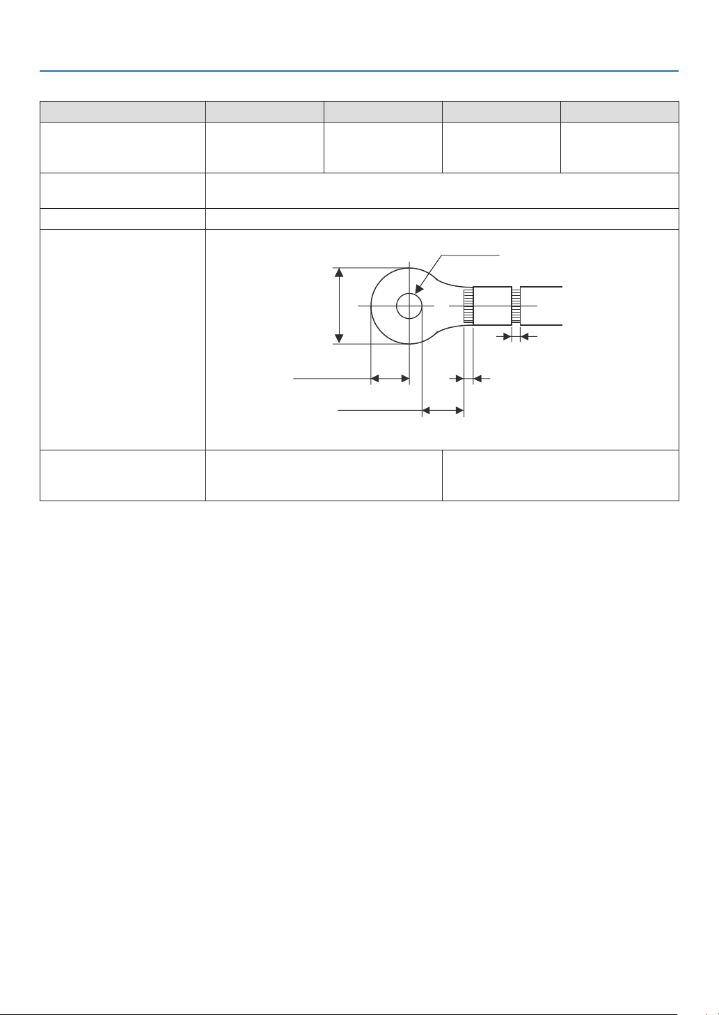
42
1. Before Setting Up Your Projector
• Erdungsklemme G (Grün/Gelb)
JIS IEC/EN UL CSA
Leiterquerschnitt kompati-
bler Kabel (bei Verwendung
lötfreier Anschlussklemmen)
14 mm
2
14 mm
2
AWG6 bis
AWG8
AWG6 oder
AWG8
Abmessungen lötfreier An-
schlussklemmen
M6 x 15
Anzugsmoment 3,5 bis 5,0 N·m
Abmessungen lötfreier An-
schlussklemmen
Min 1.0
Min 1.0
-Max 2.0
-Max 2.0
Max 11
Min ⌀6.1
Max 13
Min 7.5
Unit: mm
Empfohlene Modelle für
lötfreie Anschlussklemmen
(J.S.T-Teile)
Modell 8-8NS Bei AWG6: Modell R14-6
Bei AWG8: Modell 8-8NS
J.S.T: J.S.T. Manufacturing Co. Ltd.
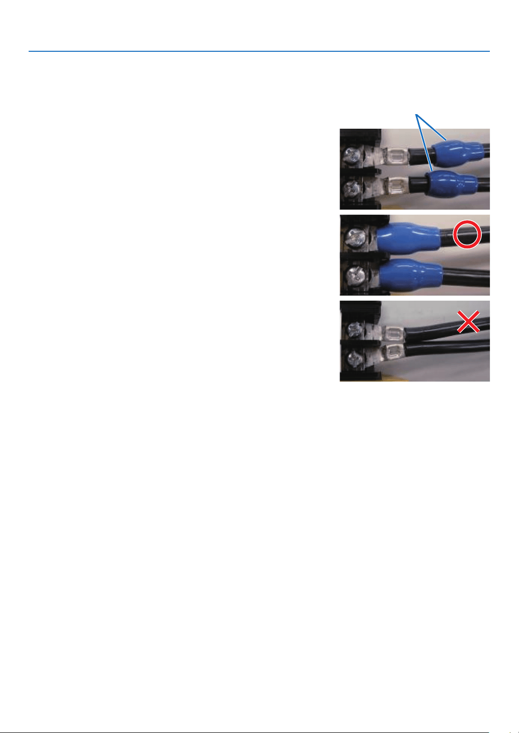
43
1. Before Setting Up Your Projector
Anschließen des Kabels
Schließen Sie zum Befestigen des Netzkabels am Klemmenblock die Drähte entsprechend den folgenden Anweisun-
gen an, sodass sich die einzelnen Drähte nicht direkt berühren können.
1. Ziehen Sie die Kabelmanschetten der Netzkabel von den
Anschlussklemmen zurück, um sicherzustellen, dass diese
nicht von der Schraube der Anschlussklemme eingeklemmt
werden.
Ziehen Sie die Kabelmanschette von der Anschlussklemme
zurück,bevorSiedieSchraubeanziehen,damitdieKabel-
manschette nicht eingeklemmt wird.
Manschetten
2. Schieben Sie die Manschetten nach dem Anziehen der
Schraube wieder an ihre richtige Position.
Ziehen Sie die Befestigungsschraube mit dem angegebenen
Drehmoment an.
Verwenden Sie Kabelmanschetten und fixieren Sie das
Isolationsmaterial,damitsichdieAnschlussklemmennicht
berühren. Wenn die Kabel ohne Kabelmanschetten an der
Netzklemmebefestigtwerden,bestehtdieGefahr,dasssich
die Anschlussklemmen wie in der Abbildung rechts berühren.
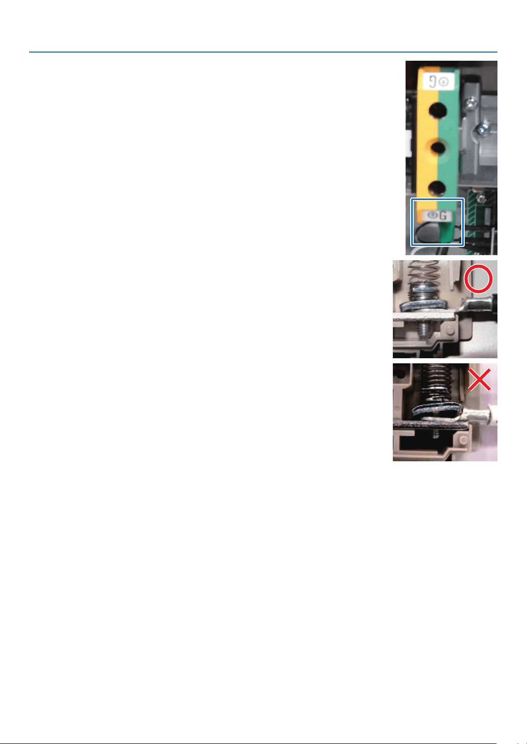
44
1. Before Setting Up Your Projector
Achten Sie beim Anschließen der Kabel an die Masseanschlusskl-
emme darauf, dass keine anderen Teile als der Quetschkabel-
schuh (z. B. Kabeladern undVerschraubungen) in der Klemmen-
befestigung eingeklemmt werden.
Richtig befestigt.
Kabeldraht ist verkantet, da eine lötfreie Anschlussklemme
mit Abmessungen verwendet wurde, die nicht den Vorgaben
entsprechen.
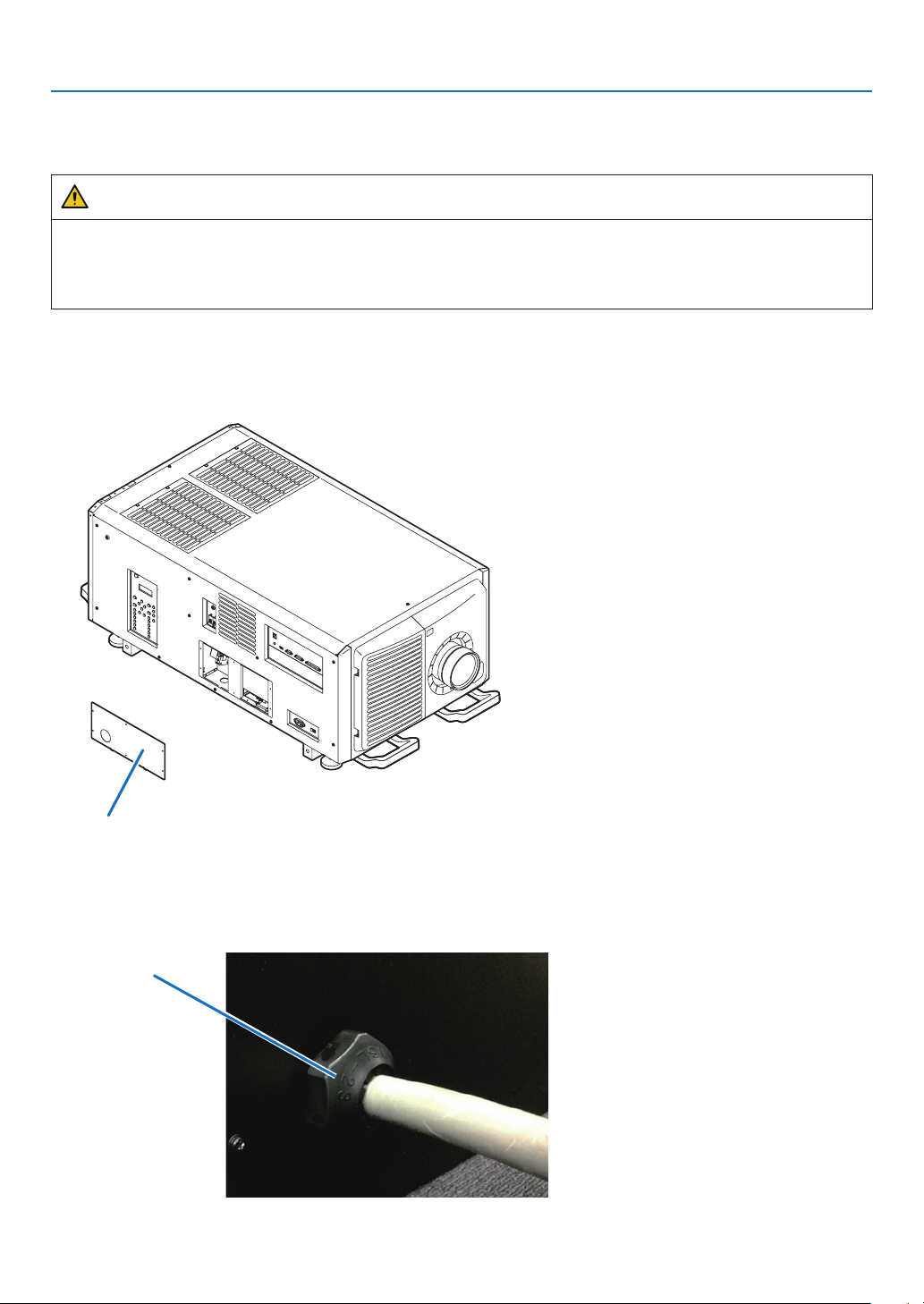
45
1. Before Setting Up Your Projector
1-9-2. Anschluss des Stromkabels (Anschluss C1)
Vorbereitung: Kreuzschraubenzieher (Nr. 2), Serviceschlüssel (Projektorzubehör)
WARNUNG
•StellenSiesicher,dassdieStromversorgungunterbrochenist,bevorSiedasStromkabelanschließen.Esbesteht
Brand- und Stromschlaggefahr.
•EsentstehtvielKriechstrom.StellenSieunbedingtsicher,dieStromversorgungnuranzuschließen,nachdem
die Erdung angeschlossen ist.
1. Entfernen Sie die Platte Inlet.
Lösen Sie die sechs Schrauben und entfernen Sie die Inlet-Platte.
EU-Region: Tauschen Sie die Inlet-Platte mit der als Zubehör beigefügten 35mm-Inlet-Platte aus.
Platte Inlet
2. Vergewissern Sie sich, dass das Stromkabel durch die Kabelöffnung passieren kann, und ziehen Sie das
Stromkabel durch die Kabelöffnung der Platte Inlet.
WennSiediebeigefügte35mm-PlatteInletbenutzen,sichernSiedasStromkabelmiteinemhandelsüblichen
Kabelfixierer in der Kabelöffnung.
Kabelxierer
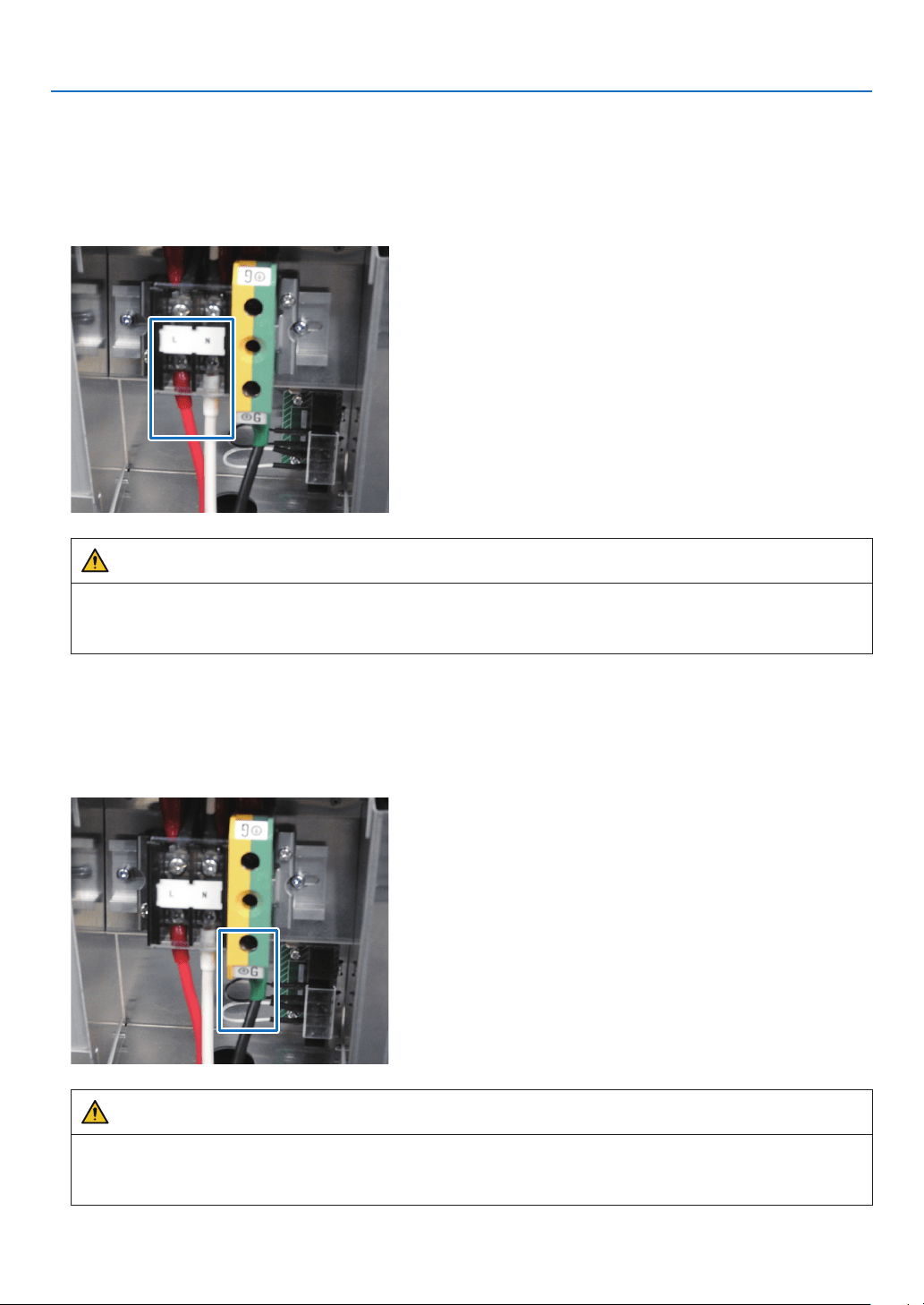
46
1. Before Setting Up Your Projector
3. Entfernen Sie den Deckel der Strombuchse.
Ziehen Sie dazu den Deckel zu sich hin und heben Sie ihn nach oben.
4. Stecken Sie die L-Leitung und N-Leitung des Stromkabels in die Anschlussbuchse und schrauben Sie sie
fest.
Stecken Sie den Crimpanschluss des Stromkabels in die Öffnung der Anschlussbuchse und schließen Sie die
Schrauben mit einem Kreuzschraubenzieher.
WARNUNG
Verschrauben Sie das Stromkabel gut in der Anschlussbuchse. Vergewissern Sie sich nach dem Schließen
der Schrauben, dass alle Stromkabel gut verschraubt sind. Wenn die Schrauben nicht richtig geschlossen sind,
können Tod und schwere Verletzungen die Folge sein.
5. Befestigen Sie den Deckel der Strombuchse.
GehenSiedabeiinumgekehrterReihenfolgezumEntfernenvor.
6. Stecken Sie das Erdungskabel in die Anschlussbuchse und schrauben Sie es fest.
SteckenSiedenCrimpanschlussdesErdungskabelsindieÖffnungderAnschlussbuchse,undschließenSie
die Schrauben mit einem Kreuzschraubenzieher.
WARNUNG
Verschrauben Sie das Erdungskabel gut in der Anschlussbuchse. Vergewissern Sie sich nach dem Schließen
der Schrauben, dass das Erdungskabel gut verschraubt ist. Wenn die Schrauben nicht richtig geschlossen sind,
können Tod und schwere Verletzungen die Folge sein.
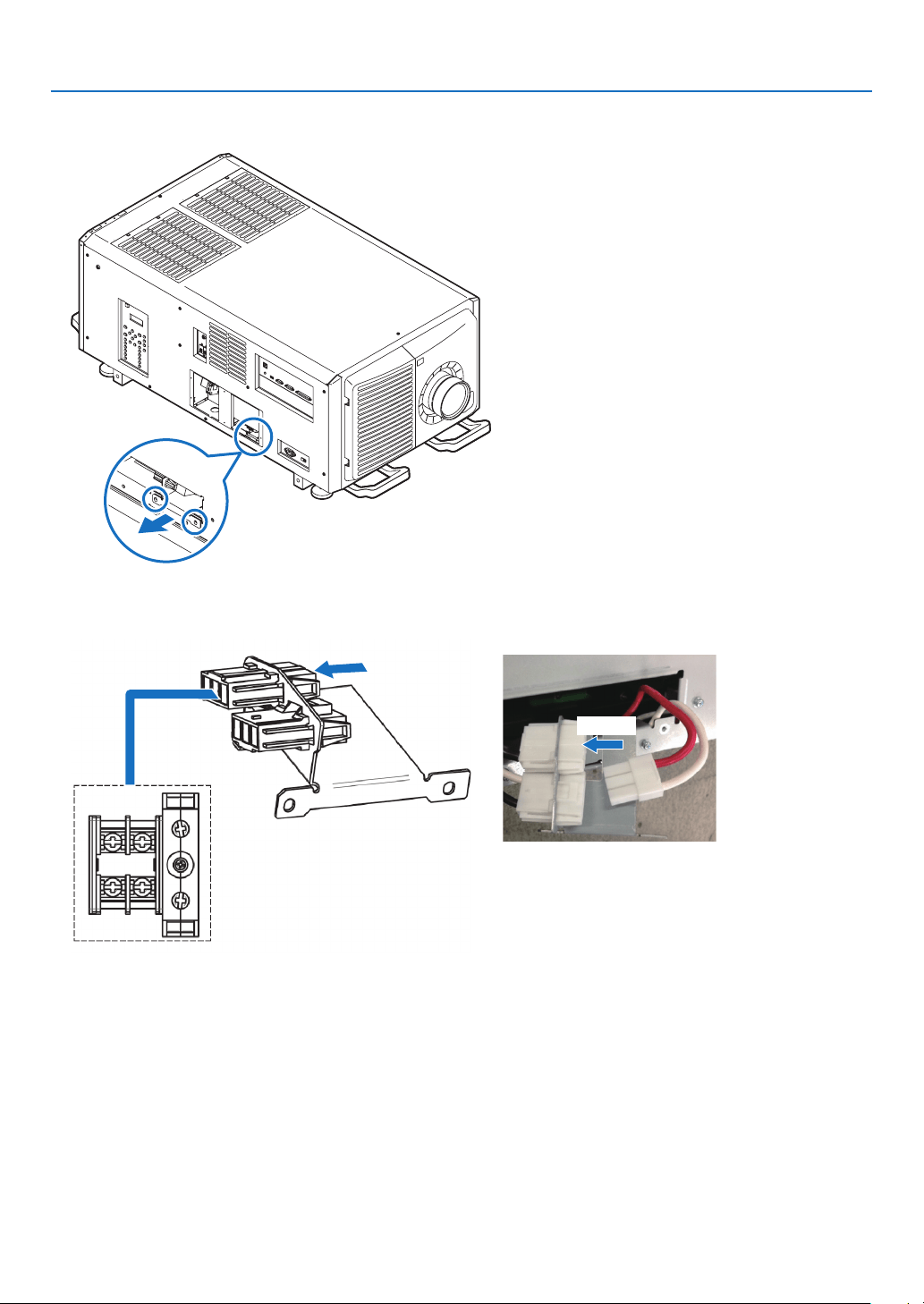
47
1. Before Setting Up Your Projector
7. Lösen Sie die zwei Fixierschrauben und entfernen Sie das Fixiermetall in Pfeilrichtung, und ziehen Sie den
Stromverbinder heraus.
8. Richten Sie die Stromversorgung über Anschluss C1 ein.
Verbinden Sie Anschluss C1 mit dem hinteren Verbinder.
Anschluss
Anschluss
9. Legen Sie den Stromverbinder und das Fixiermetall zurück in ihre ursprüngliche Position, und schließen
Sie die zwei Fixierschrauben.
10
. Befestigen Sie die Platte Inlet mit sechs Fixierschrauben.
EU-Region: Befestigen Sie die als Zubehör beigefügte 35mm-Platte Inlet.
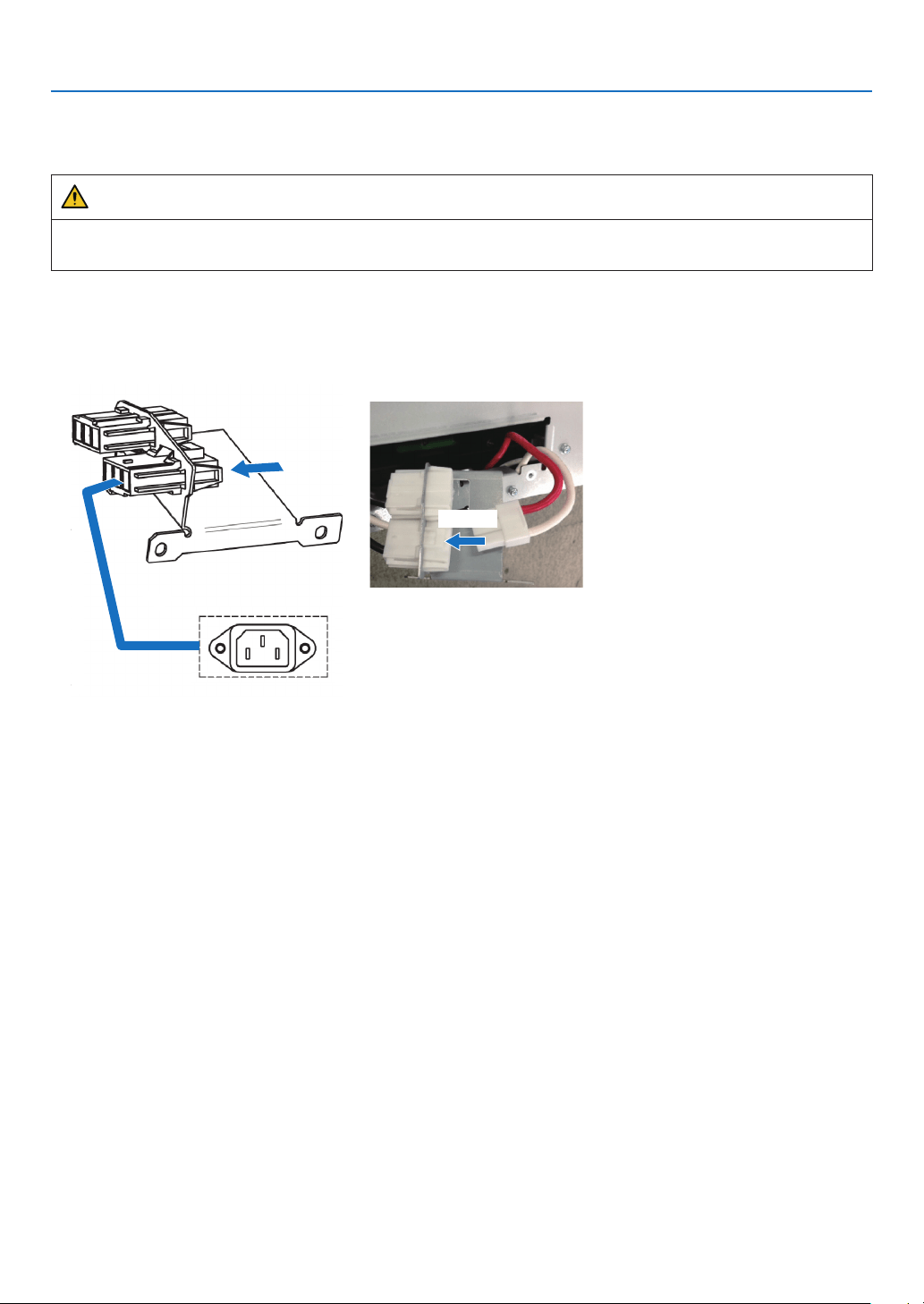
48
1. Before Setting Up Your Projector
1-9-3. Anschluss des Stromkabels (Anschluss C2)
Vorbereitung: Kreuzschraubenzieher (Nr. 2), Serviceschlüssel (Projektorzubehör)
WARNUNG
Stellen Sie sicher, dass die Stromversorgung unterbrochen ist, bevor Sie das Stromkabel anschließen. Es besteht
Brand- und Stromschlaggefahr.
1. Führen Sie die Schritte 1 bis 7 unter „1-9-2. Anschluss des Stromkabels (Anschluss C1)“ (Seite
45) aus.
2. Richten Sie die Stromversorgung über Anschluss C2 ein.
Verbinden Sie Anschluss C2 mit dem vorderen Verbinder.
Anschluss
Anschluss
3. Legen Sie den Stromverbinder und das Fixiermetall zurück in ihre ursprüngliche Position, und schließen
Sie die zwei Fixierschrauben.
4. Befestigen Sie die Platte Inlet mit sechs Fixierschrauben.
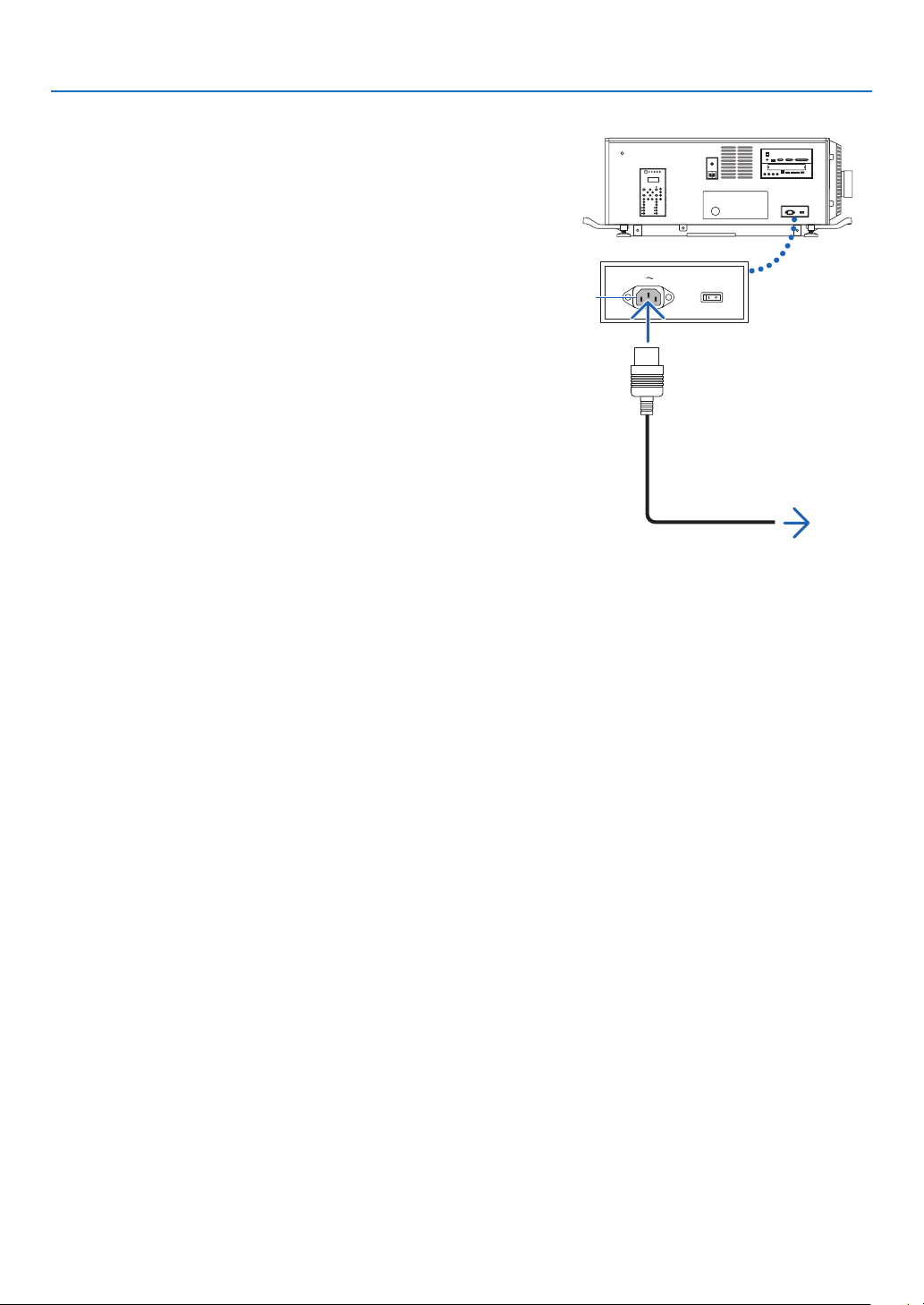
49
1. Before Setting Up Your Projector
5. Schließen Sie das Netzkabel an.
(1) Schließen Sie das Netzkabel an.
Schließen Sie das Netzkabel an den Projektor an.
Zur Wandsteckdose
AC input
(2) Schließen Sie das Netzkabel an die Netzsteckdose an.
Dadurch ist der Anschluss des Netzkabels abgeschlos-
sen.
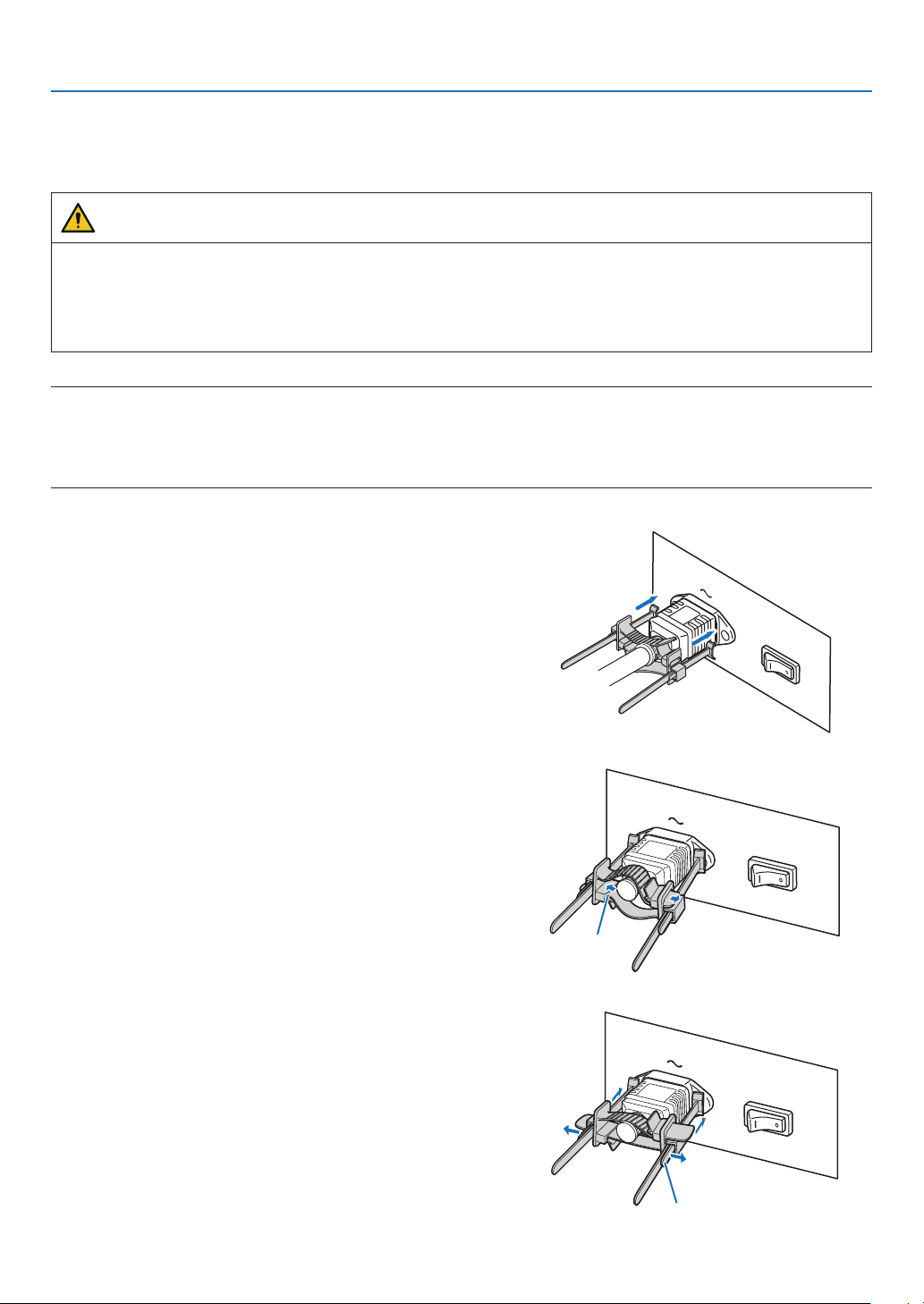
50
1. Before Setting Up Your Projector
Anbringen des Netzkabelstoppers
Um zu verhindern, dass sich das Netzkabel unbeabsichtigt aus dem Wechselstromeingang des Projektors löst, bringen
Sie den im Lieferumfang enthaltenen Netzkabelstopper an, um das Netzkabel zu sichern.
ACHTUNG
•Umzuverhindern,dasssichdasNetzkabellöst,stellenSiesicher,dassalleStiftedesNetzkabelsvollständig
in den Wechselstromeingangsanschluss des Projektors eingesteckt sind, bevor Sie den Netzkabelstopper ver-
wenden, um das Netzkabel zu xieren. Ein lockerer Kontakt des Netzkabels kann einen Brand oder Stromschlag
verursachen.
•BündelnSiedasNetzkabelnicht.AnderenfallskannWärmeerzeugtodereinBrandverursachtwerden.
HINWEIS
•KlemmenSiedasNetzkabelnichtmitanderenKabelnzusammen.DadurchkannelektrischesRauschenerzeugtwerden,welches
dasSignalkabelstörenkann.
•FührenSiedasBandnichtverkehrtherumein.WenndasBandeinmalangebrachtwordenist,kannesnichtmehrausdemSchlitz
entferntwerden.
1. Bringen Sie das Klemmenband auf die Netzkabelseite
und führen Sie das Ende des Bands am Netzkabelstop-
per in den Schlitz neben dem Anschluss AC IN an der
Anschlussplatte ein.
Befestigen Sie den Netzkabelstopper in gleicher Weise
auf der anderen Seite.
2. Führen Sie jedes Band durch die Schlitze im Netzka-
belstopper.
FührenSiedieBändersohindurch,dassdasNetzkabel
von oben und unten gehalten wird.
Band
3. Schieben Sie die Klemme bis zum Anschlag des Netz-
kabels.
Durch Ziehen des Knopfes in Pfeilrichtung können Sie die
Klemmenposition justieren.
SobalddieKlemmenpositionjustiertwurde,lassenSie
denKnopflos,umdieKlemmezusperren.
Knopf

51
1. Before Setting Up Your Projector
4. Ziehen Sie das Band zur Befestigung des Netzkabels.
Durch Ziehen des Knopfes in Pfeilrichtung können Sie die
Bandposition justieren.
Ziehen Sie das obige und das untere Band gleichmäßig
im Wechsel.
SobalddieBandpositionjustiertwurde,lassenSieden
Knopflos,umzusperren.
Knopf
Knopf
Damit ist die Anbringung des Netzkabelstoppers abgeschlossen.
Entfernen des Netzkabels aus dem Netzkabelstopper
1. Ziehen Sie den Klemmenknopf, um das Band zu lösen.
2. Ziehen Sie den Knopf und schieben Sie die Klemme
vom Netzstecker fort.
ACHTUNG
•DerProjektorkann vorübergehend heiß werden, wenn die Stromversorgung ausgeschaltet wird oder wenn der
Wechselstrom getrennt wird, während der Projektor projiziert. Seien Sie im Umgang mit dem Projektor vorsichtig.

52
This chapter describes the preparations necessary for using the projector for the rst time.
2-1. Initial settings flow
Step 1
•Updatingthesoftware(thispage)
Step 2
•InstallingtheLVunitontheprojector(→ page
59)
Step 3
•Attachingthecontrols/indicatorpaneldisplaylabeltotheprojector(→ page
61)
NOTE:
•BesuretoupdatethesoftwarebeforemountingtheLVunit.UpdatingthesoftwareaftermountingtheLVunitcancauseanupdate
failure.
2-2. Updating the software
2-2-1. Update flow
Step 1
•InstallingtheDCConthecomputer(→ page
53)
Step 2
•ConnectingthecomputertotheprojectorandstartinguptheDCC(→ page
54)
Step 3
•Updatingtheprojector(→ page
56)
Step 4
•ExitingtheDCC(→ page
58)
2. Configuring the projector’s initial settings

53
2. Configuring the projector’s initial settings
2-2-2. Installing the DCC on the computer
Overview of DCC
DCC is software for controlling and managing projectors via the network. A maximum of 20 units can be congured and
managed from a computer by connecting to the projectors via the network from a computer where DCC is installed.
TIP:
•DCCsupports“English”,“Chinese(Simplied)”,and“Japanese”fordisplay.
Supported devices
Contact your distributor for information about which devices are supported by DCC.
Operating environment of DCC
This software can be used with the personal computer that lls the following environments.
SupportedOSMicrosoft Windows 7/8/8.1/10 (32-bit or 64-bit)
Microsoft Windows Server 2008/2012
LAN environment Except for supported host names of standard TCP/IP, a xed IP address is required
for most devices that are directly connected to a LAN.
HDD capacity 70 MB
(Note)
or more is required for installation.
(Note): Necessary capacity can vary by updating the DCC.
Installing the DCC
This section describes the installation procedure of DCC. Use the same procedure as for installation for version
upgrading (installation by overwriting).
Preparatory operation:
•BootupyourPC’sWindows.
•IfyouhavealreadystartedWindows,quitallrunningapplicationprograms.
If you do not quit all running programs before installing the DCC Software, you risk having unsuccessful installation.
NOTE
•Abouttheprivilegesusedduringsoftwareinstallationanduninstallation
-ForWindows8/Windows10
Performasauserwhohas“Administrator”selectedastheaccounttype.
•OnWindows7,ifthe“UserAccountControl”windowisdisplayed,click“Allow”.OnWindows8/Windows10,click“Yes”.
1. Save the EXE file of the DCC in the local drive of the personal computer.
2. Double-click the EXE file that was saved.
The installer starts.
3. Install the DCC (version upgrading) according to the instruction of the installer.
DCC has now been installed (the version has been upgraded).
DCC uninstalling
Uninstall the Software from the menu shown below.
•ForWindows10
Right-click [Start] → [Control Panel] → [Uninstall a program]
•ForWindows8
Hold down the [Windows] key and press the [X] key → [Control Panel] → [Uninstall a program]
•ForWindows7
[Start] → [Control Panel] → [Programs] → [Programs and Features]
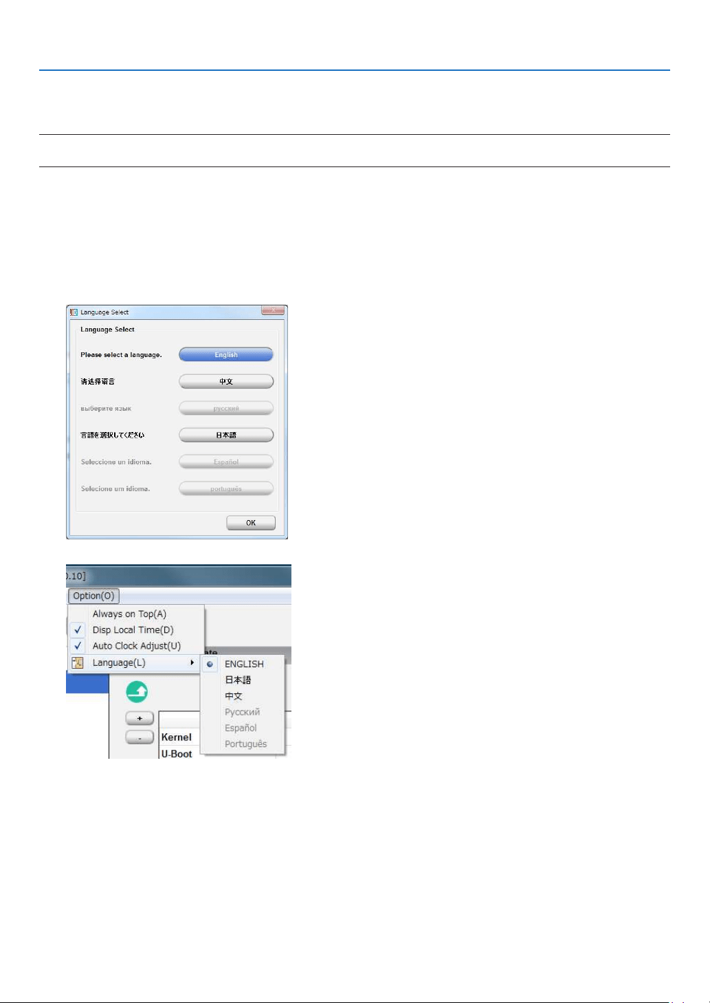
54
2. Configuring the projector’s initial settings
2-2-3. Connecting the computer to the projector and starting up the DCC
1. Connect the computer on which the DCC is installed to the LAN port on the projector using a commercially
available LAN cable.
NOTE
•TheDCCcannotbeconnectedtotheHDBaseTport.
2. Set the projector to the standby mode.
Follow the instructions at “4-2. Turning on the Projector” (→ page
70) and set the projector to the standby mode.
3. Start up the DCC.
FromtheWindows[Start]menu,select[AllPrograms]→ [Projector User Supportware] → [DCC].
The DCC starts up.
TIP:
•
Ifthe“LanguageSelect”screenappears,selectthedisplaylanguage.
•Tochangethedisplaylanguage,click“Option”-“Language”fromthetoolbar.
•IfaChinesefontorJapanesefontisnotinstalledonyourPC,thendisplayingChineseorJapaneseisnotsupportedandthe[
中文]buttonor[日本語]buttonisnotdisplayed.
•DCCsupports“English”,“Chinese(Simplied)”,and“Japanese”fordisplay.
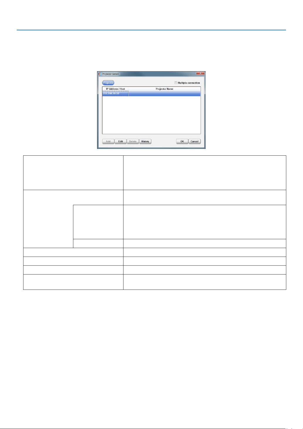
55
2. Configuring the projector’s initial settings
4. Setting a connection destination
WhentheDCCisactivated,theProjectorSelectscreenisdisplayed.ThisscreenisusedtosettheIPaddressor
host name of the connection destination device. The connection destination devices that have been connected
toaresavedinahistory,andtheconnectiondestinationcanbeselectedfromthishistory.Thisscreencanbe
displayed also by selecting “Select Projector... ” from the tool bar.
Multiple connection Allows to set multiple connection destination devices.
Without check: Set only 1 connection destination device.
With check: Set multiple connection destination devices. When mul-
tiple destination devices are set, the currently connected device is
located at the top of the connection list.
Enter the network setting of the connection destination device. Select
the IP address or the host name and enter the necessary items.
IP Address/Host Enter the IP address.
•Whenenteringanaddressfromtheconnectionhistory,double-
click the IP address/Host eld, then select the connection history
displayed.
Valuesetatfactoryshipment:192.168.10.10
Projector Name Displays the host name of the connection destination device.
“Add” button Adds a connection destination device.
“Edit” button Sets the connection destination device.
“Delete” button Deletes the connection destination device.
“History” button Edits (or deletes) the information history of the connection destina-
tion device.
Check that the IP address is set to the factory default of “192.168.10.10”, then click the [OK] button.
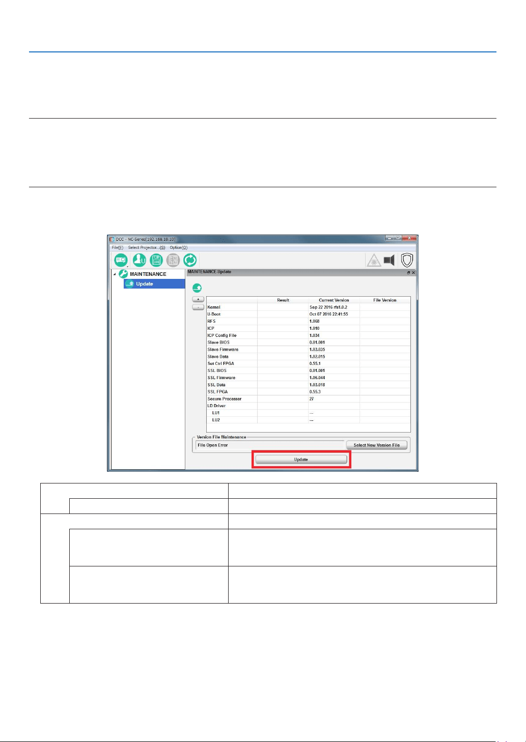
56
2. Configuring the projector’s initial settings
2-2-4. Updating the projector
Preparation:
•Obtainthelatestreleasepackageandstoreitinalocaldriveonyourcomputer.
NOTE
•Performtheupdatebyadheringtothefollowingwarnings.Ifyoudonotadheretothesewarnings,thereisariskthattheprojector
willnolongerbeabletostartcorrectly.
•Donotturnoffthemainpowertotheprojectorduringtheupdate.
•DonotturnoffthePCduringtheupdate.Turnpowersavingfunctionsoff.
•DonotdisconnecttheLANcableconnectingthePCandprojectormainunitduringtheupdate.
1. On the [MAINTENANCE] → [Update] screen, click the [Update] button.
The Update screen appears.
Version File Maintenance Displays the denition le (*.npversion) that is read by DCC.
“Select New Version File” button Sets the selected le as the new version le.
Update Displays the screen for selecting the method for updating.
“Full-Auto”button Begins Full-Auto Update. When the Full-Auto Update nishes, the
button changes to “Update End”. Click the “Update End” button to
nish the Full-Auto Update (shuts down the projector).
“Semiauto”button Begins Semiauto Update. When the Semiauto Update nishes, the
button changes to “Update End”. Click the “Update End” button to
nish the Semiauto Update (shuts down the projector).
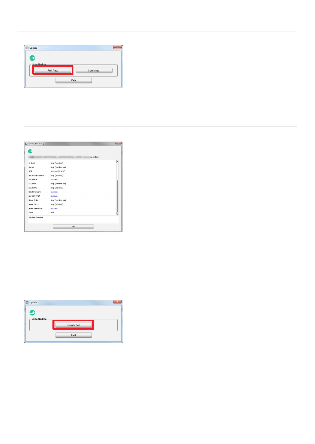
57
2. Configuring the projector’s initial settings
2. Click the “Full-Auto” button.
3. Select the “nprelease” file stored on the local drive, then click the “Open” button.
A progress bar is displayed and the update begins. The update proceeds automatically.
NOTE
•Duringupdating,theprojectorturnsonautomatically.Afterthat,theprojectorautomaticallyreturnstothestandbystate.
4. Check the results of the update.
If“Error”isnotdisplayedonthescreenbottomofcolumn,theupdatehascompletedsuccessfully.
Oncetheupdateiscompleted,amessagesuchasthefollowingappearsbelowthescreen.
If the update is successful: Update Success
If the update is unsuccessful: Update has failed
5. Once the update is successful, click the “Exit” button.
The All Update screen closes.
6. Click the “Update End” button.
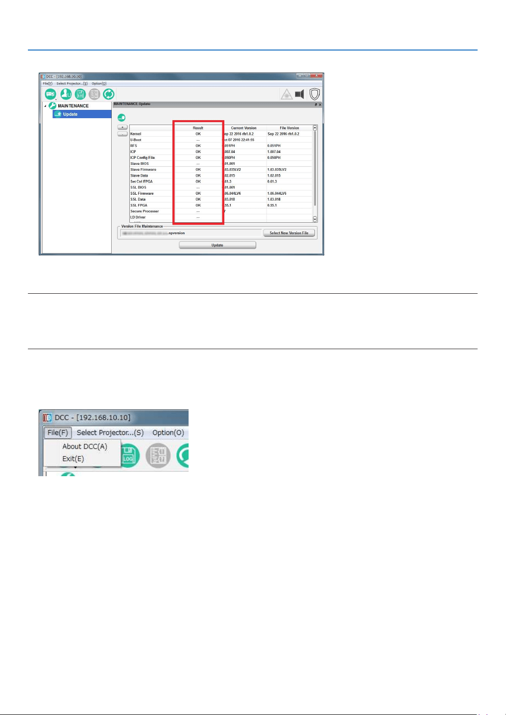
58
2. Configuring the projector’s initial settings
7. Check that all of the results are “OK”.
If Different is displayed
Return to step 1 and execute the update again.
NOTE
•When,afterhavingmountedtheLVunit,updatingtheprojectorforthepurposeofversionupgrade,insteadoftheprojector’s
initialsettings,settheprojector’sIPaddresstoaconnectiondestination,andexecutefromstep1throughstep7.
Theprojector’sIPaddresscanbecheckedonthesettingofWIREDLANfromtheonscreenmenu.
•TheupdateforthepurposeoftheinitialsettingsmustbedonebeforemountingtheLVunit.
2-2-5. Exiting the DCC
1. Click “File”.
The [File] menu will appear.
2. Click “Exit”.
The DCC will close.
3. Turning off the Projector
Follow the procedure at “4-6 Turning off the Projector” (→ page
85)toturnofftheprojector’spower,thendiscon-
nect the AC power.
TIP:
•
Tochecktheprojector’sinformationandlogusingtheDCC,see“7-8.UsingtheDCC’sfunctions”(→page
118).
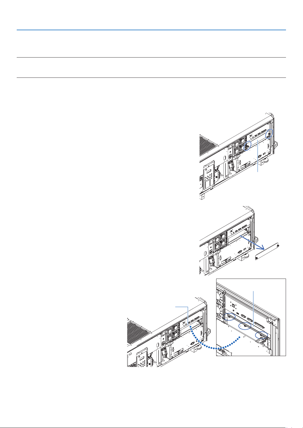
59
2. Configuring the projector’s initial settings
2-3. Installing the LV unit
Mount the LV unit on the projector unit.
NOTE:
•Theprojectorcannotbeusedalone.BesuretomounttheLVunitbeforeusingtheprojector.
•Beforemounting,besuretoturnofftheprojector’spower,disconnecttheACpowerandunplugthepowercord.
Preparation:
•Prepare a Phillips screwdriver.
•Remove the side panel. (→ page
17)
1. Remove slot blocking panel A.
(1)
Loosen the blocking panel A screws (2) until they turn freely.
The screws do not come off.
Blocking panel A
(2) Remove blocking panel A.
2. Remove slot blocking panel B.
(1)
Loosen the blocking panel B screws
(3) located inside the slot until they turn
freely.
The screws do not come off.
Blocking panel B
Blocking panel B
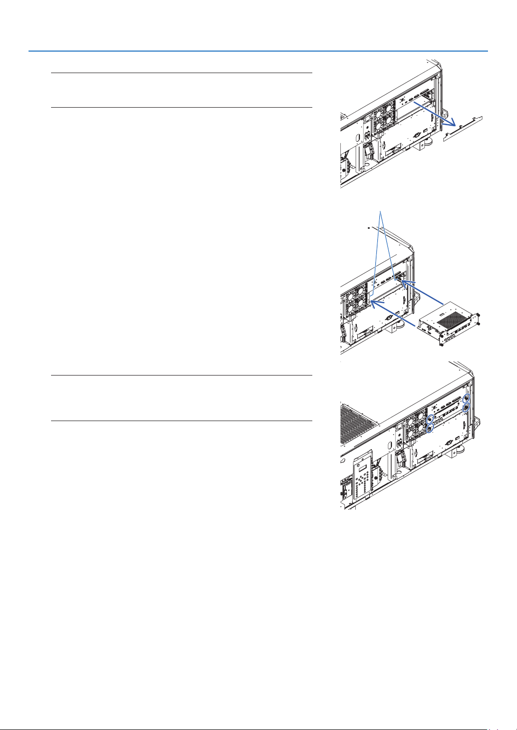
60
2. Configuring the projector’s initial settings
(2) Remove blocking panel B.
NOTE:
•AfterremovingblockingpanelsAandB,besuretostoretheminasafe
place.
3. Mount the LV unit onto the projector.
(1) Insert the LV unit by following the guide on either side of the slot.
guide (left/right)
(2) Tighten the screws (4) on the front of the LV unit to fasten.
NOTE:
•SettheLVunit’sdisplaysintheproperdirection,accordingtotheprojec-
tor.InsertingtheLVunitupsidedowncanresultindamage
•Tightenthescrewssecurely.
This completes installing of the LV unit.
Next, attach the controls/indicator panel display label.
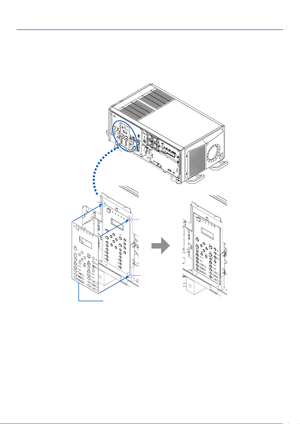
61
2. Configuring the projector’s initial settings
2-4. Attaching the controls/indicator panel display label
Attach the supplied controls/indicator panel display label to the projector’s control panel.
(1) Peel off the default attached label.
(2) Peel the label off the backing paper and attach it to the projector’s control panel.
•Lineupthecornersofthelabelwiththefourprotrusions.
•Install carefully, making sure the label does not touch the buttons.
Protrusion
Protrusion
Protrusion
Controls/indicator panel display label
This completes mounting of the controls/indicator panel display label.
Mount the side panel. (→ page
17)

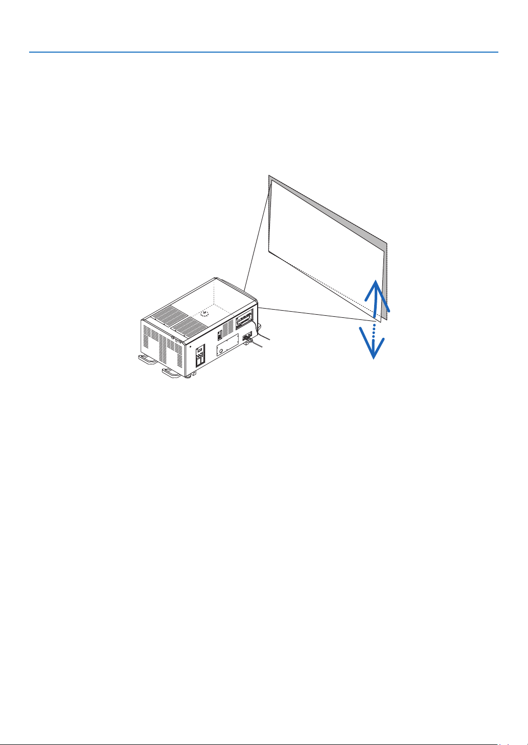
63
3. Setting Up Your Projector
3-2. Installing the projector
Move the projector to the projection position and install it corresponding to the screen and projection conditions.
The projector must be placed square to the screen otherwise keystone distortion may appear on the screen. For
setting the projector perpendicular to the screen when viewed from the side, utilizing the level adjusters equipped at
each corner of the projector bottom. (→ page
76)
Example for adjustment
To install as shown below, see “7-7. Special Installation” (→ page 113).
•Installing the Projector on the Ceiling
•Installing using eye bolts
•Installing with free tilting
•Portrait projection (vertical orientation)
•Multi-Screen Projection

64
3. Setting Up Your Projector
3-3. Mounting the Lens Unit
The lens units that can be attached to this projector are shown in the following table.
MODELMagnifying
L2K-10F1 0.93
L4K-11ZM1.24–1.73
L4K-15ZM1.52–2.10
L4K-20ZM1.98–3.34
L2K-30ZM2.71–3.92
L2K-43ZM13.91–5.52
L2K-55ZM15.00–7.80
NOTE:
•TheotherNECoptionallensesarenotavailableonthismodel.
•Theprojectorandlensesaremadeofprecisionparts.Donotsubjectthemtoshockorexcessiveforces.
•Removethelensunitwhenmovingtheprojector.Ifnot,thelenscouldbesubjecttoshockwhiletheprojectorisbeingmoved,
damagingthelensandthelensshiftmechanism.
•Whenremovingorinstallingthelensunit,returnthepositionofthelenstothecenterbeforeturningoffthepowertotheprojector.
Ifthepositionofthelensisnotreturnedtocenter,thefrontcoverwillinterferewiththelensandthecovercannotberemovedor
installed.
•Wheninstallingorremovingthelensunit,rstconrmthatthemainpowerswitchtotheprojectorisoff,andthendisconnect
theACpowersupply.AftertheACpowersupplyhasbeendisconnected,allowtheprojectortosufcientlycoolbeforestarting
thiswork.
•Nevertouchthelenssurfacewhiletheprojectorisoperating.
•Beverycarefulnottoletdirt,grease,etc.,onthelenssurfaceandnottoscratchthelenssurface.
•Performtheseoperationsonaatsurfaceoverapieceofcloth,etc.,topreventthelensfromgettingscratched.
•Whenleavingthelensofftheprojectorforlongperiodsoftime,mountDust-proofcushionontheprojectortopreventdustor
dirtfromgettinginside.
Mounting and adjustment of optional lenses must be performed by a qualied technician.
The lens unit mounting procedure is roughly the same.
•ForL2K-30ZM,L2K-43ZM1,andL2K-55ZM1,attachthegearboxcover.
•FortheL4K-20ZM,thelenscover'sringmustberemoved.
At the same time, the image adjustment mechanism by manual besides the focus adjustment is also equipped on
theL4K-11ZM,L4K-15ZMandL4K-20ZM.
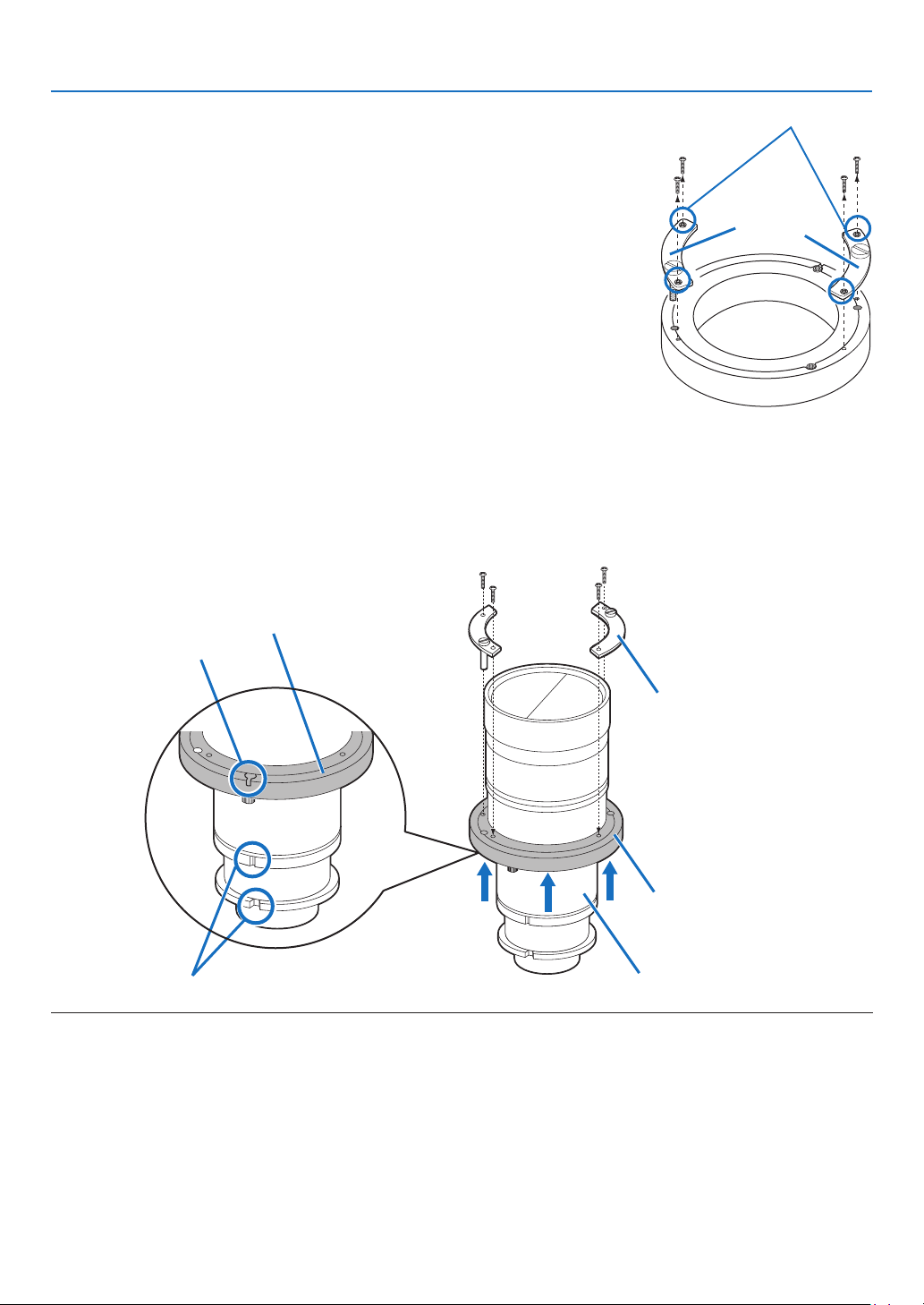
65
3. Setting Up Your Projector
1. Remove two mounting metals of the lens holder.
Remove four mounting screws and remove two mounting
metals.
These four mounting screws and two mounting metals will be
used for lens holder mounting.
Mounting screws
Mounting
metals
2. Place the lens with the face upward.
Check that the place for putting the lens is flat before the work.
It is recommended to keep the lens cap set so as to protect the lens from any damage.
3.
Insert the lens holder from under the lens.
Align the lens holder slits with two lens insertion guides and insert the lens holder.
4.
Fix two mounting metals of the lens holder with four mounting screws.
Lens insertion guides
Lens holder
Lens holder
mounting metal
Slit
Lens
Lens holder
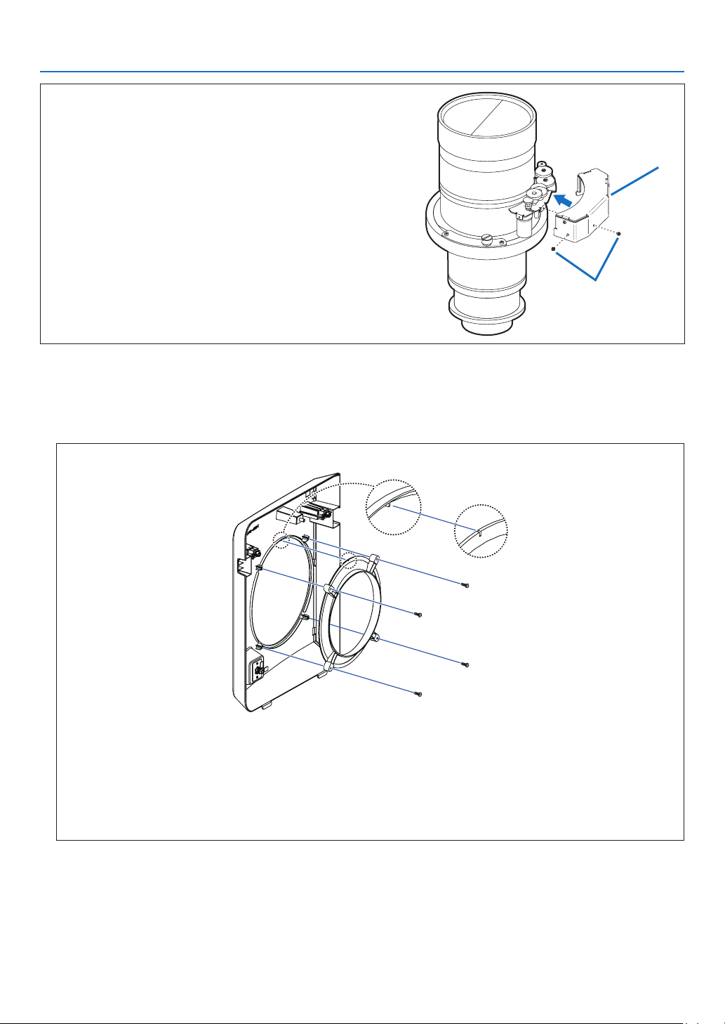
66
3. Setting Up Your Projector
(Applicable lens units: L2K-30ZM, L2K-43ZM1 and L2K-
55ZM1)
Attach the gearbox cover.
Attach the attached gearbox cover with two screws.
Fixing screws
Gearbox cover
5. Remove the lens cap.
Ifthelenshasalenscap,removethelenscap.
6. Remove the lens cover.
Forremovalofthelenscover,Referto“1-5-1. Removing and Mounting the Lens Cover” (page
15).
WhenmountingtheL4K-20ZM,loosenthescrews(4)onthebackofthelenscover,thenremovethering.
•Be sure to store the ring and screws you have removed in a safe place.
•
WhenreplacingtheL4K-20ZMwithanotherlensunit,besuretomounttheringonthelenscover.
Mounting the ring
1. Line up the protruding part on the back of the lens cover with the notch in the ring (the circle on the
diagram).
2. Tighten the screws (4).
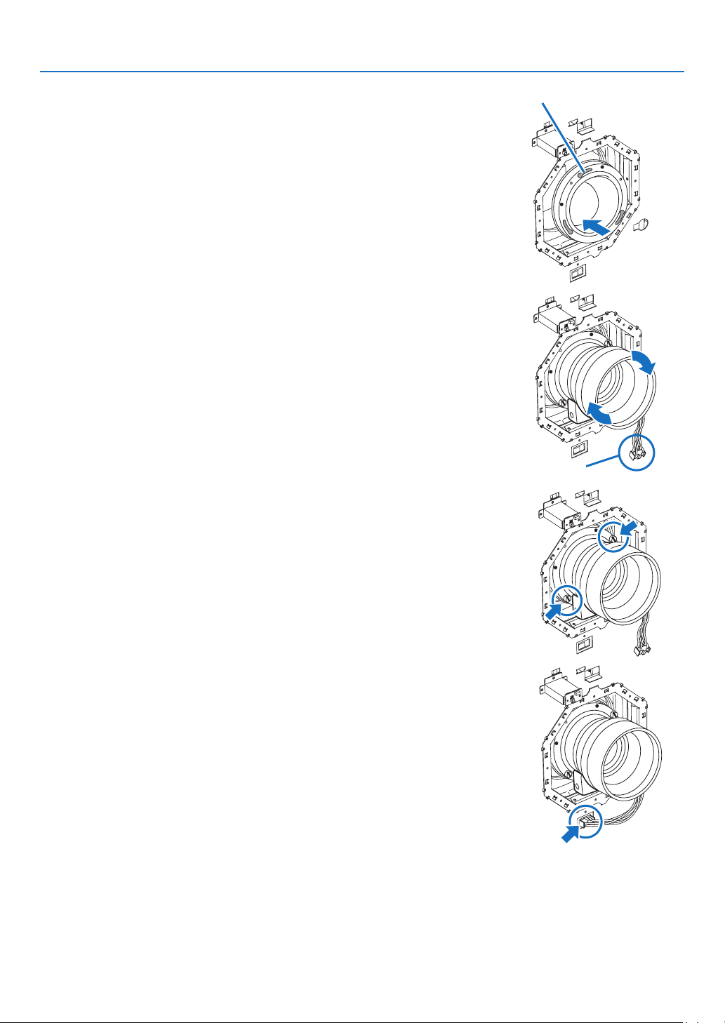
67
3. Setting Up Your Projector
7. Hold the lens unit with its guide faced upward and insert
the lens until it cannot go further.
Insert the lens holder into the fixing hole of the lens ring and
mount it with rotating it clockwise.
Pay attention not to catch the lens control cable here.
Fixing hole of the lens ring
Control cable
8. Tighten the two fixing screws for the lens holder.
9. Connect the control cable.
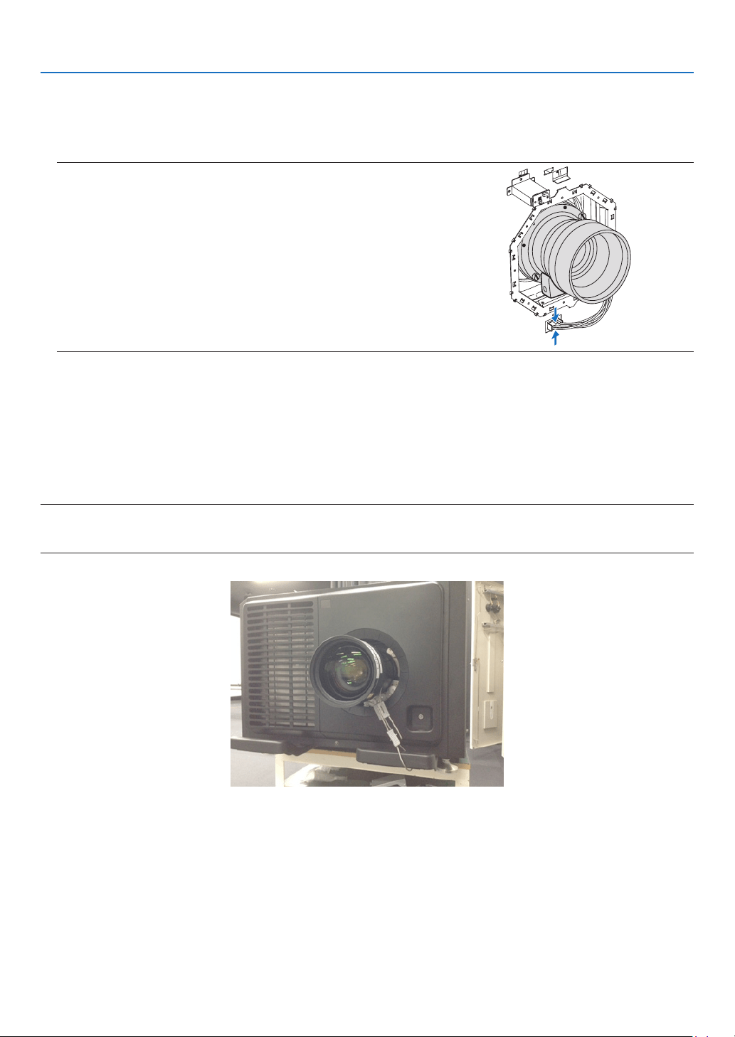
68
3. Setting Up Your Projector
Preventing the lens unit from falling
When suspending the projector, from the ceiling or otherwise, use commercially available wire rope and an attach-
ment to secure the lens unit. In this case, allow about 20 mm of exure of the wire rope for the lens shifting range.
•Recommended wire: Rope diameter 3.0 mm
•Place the wire around the lens unit and the projector’s handle, then tighten it with the attachment to fasten it in place.
NOTE:
•Tootightwireropecancausestructuralfailureofthelensshiftwhiletooloosewireropecancausethelensunittofalloff.Be
suretoadjusttheexureofthewireropetoallowfor20mmofexureandsecureit.
10
. Attach the lens cover.
Fordetailsonattachingthelenscover,referto“1-5-1.RemovingandMountingtheLensCover”(page
15).
This completes the installation of the lens unit. Removal is done in reverse order of installation.
NOTE:
•Whenunpluggingthelenscontrolcableatthetimeoflensunitreplacement,
besuretodosobyholdingbothtopandbottomsidesoftheconnector.
Doingsobyholdingbothleftandrightsidesoftheconnectormaycausethe
connectorattheprojectortocomeoff.

69
4. Projector Adjustment and Connecting
4-1. Flow of Adjustment and Connecting
Perform the adjustment and connection of the projector according to the the following procedure
Step 1
•TurningontheProjector(→ page
70)
Step 2
•Selectingtheprojectororientation(→ page
74)
Step 3
•AdjustingthePictureSizeandPosition(→ page
75)
Displaythetestpatterntoadjustthescreensize,screenratioandfocus.
Step 4
•ConnectingtoOtherEquipments(→ page
82)
Step 5
•Turning off the projector (→ page
85)
This chapter explains the adjustment and connection of the projector with Steps from 1 to 5.
The adjustment and connection of the projector is completed by performing all steps in order
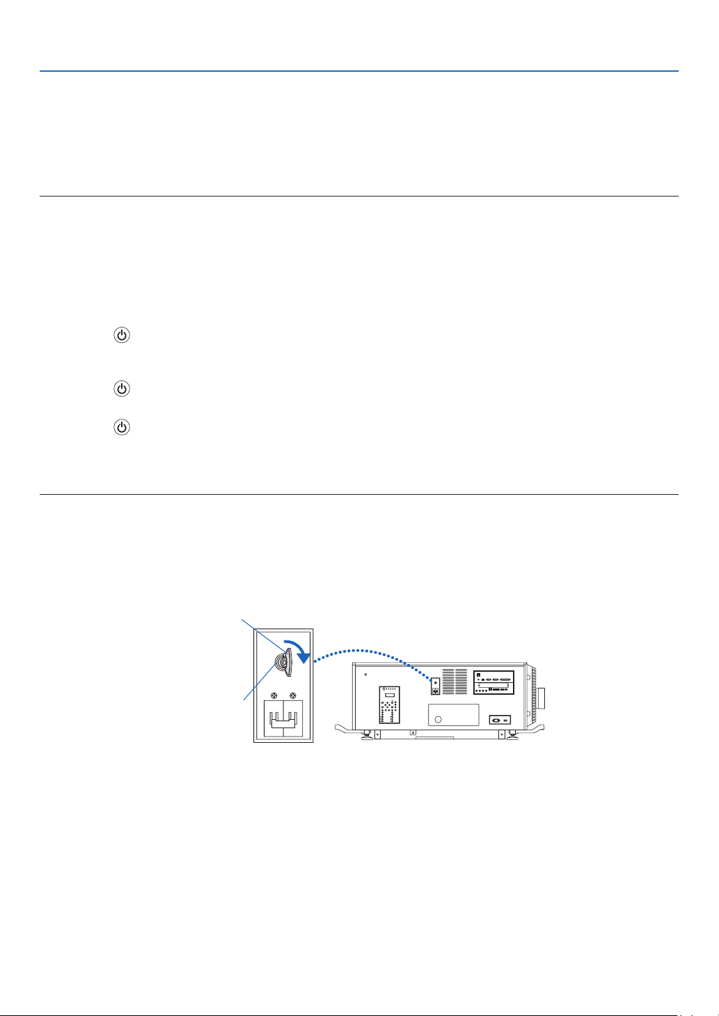
70
4. Projector Adjustment and Connecting
4-2. Turning on the Projector
Please contact your dealer/distributor to connect the power cable.
Preparation:
•Connectthepowercabletotheprojector.(→ page
24)
•SupplyACpowertotheprojector.
NOTE:
•TurnofftheprojectorpowerswitchandlightpowerswitchtotheprojectorwhencuttingACpowertotheprojector.Shuttingdown
theACpowerwhiletheprojectorpowerswitchandlightpowerswitchisonwilldamagetheprojector.
•Turningonandofftheprojectorinvolvesatwo-stepoperation;the“projectorpowerswitchandlightpowerswitch”andthe
“POWERbutton”(POWERONandOFFontheremotecontrol).
Turning power on. (See this page)
1. Turn on the “projector power switch and light power switch” of the projector.
Your projector is set in a standby state.
2. Press the
(POWER) button on the projector cabinet or the POWER ON button on the remote control.
Your projector is turn on.
Turning power off. (→ page
85)
1. Press the (POWER) button on the projector cabinet or the POWER OFF button on the remote control.
The confirmation message will be displayed.
2. Press the
(POWER) button or the POWER OFF button again.
Your projector is set in a standby state.
3. Turn off the “projector power switch and light power switch” of the projector.
Your projector is turned off.
1. Remove the lens cap.
2. Insert the administrator key vertically, and turn it to the right.
The administrator key can no longer be removed. The projector will not function unless the administrator key is
inserted.
Administrator switch
Administrator key
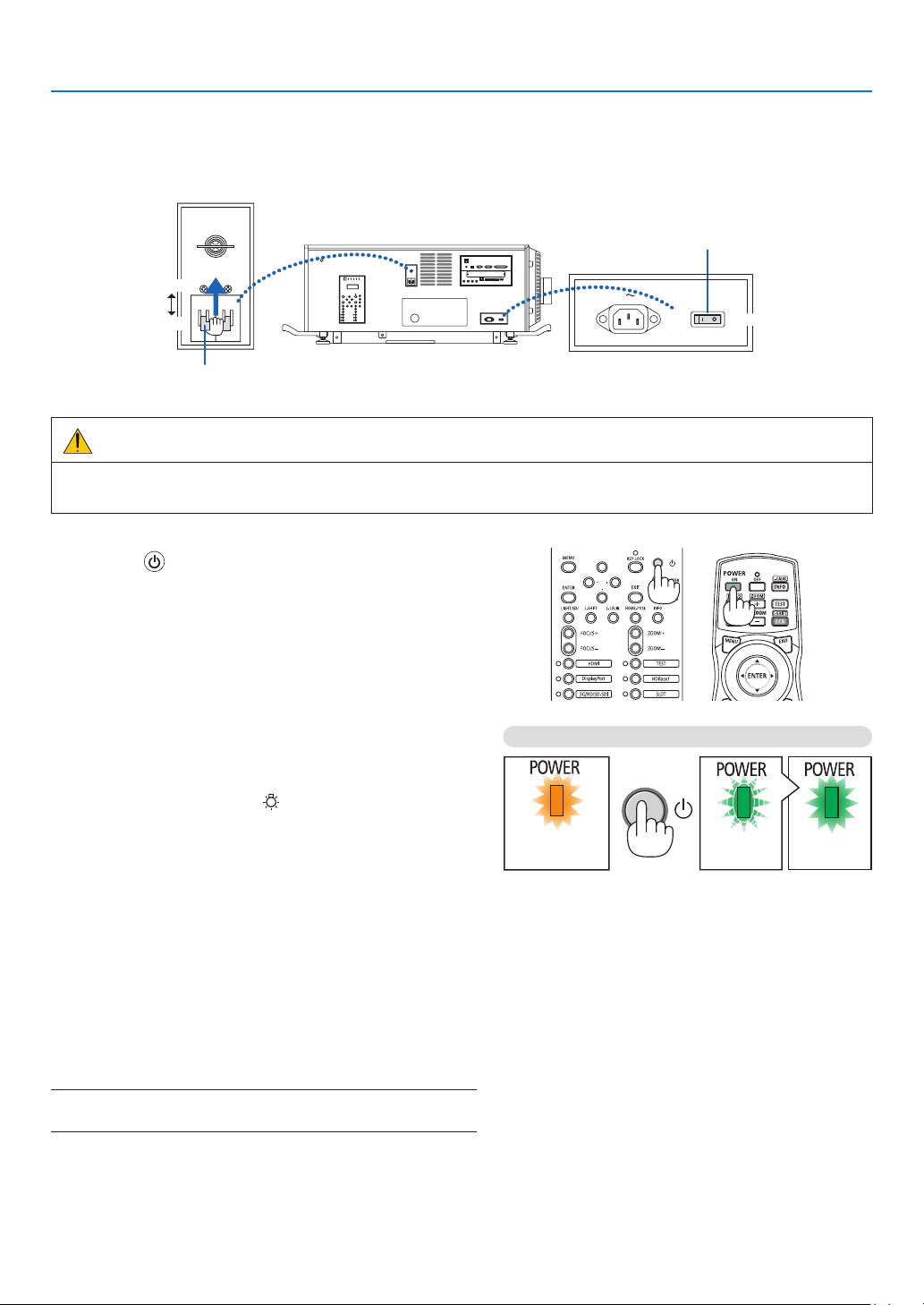
71
4. Projector Adjustment and Connecting
3. Turn on the light power switch ([1]) then the projector power switch ([2]) on the side of the projector.
The POWER indicator lights up orange.
•Thebuzzersoundisreleasedwhen[NOTIFICATIONSETTING]for[BUZZER]isON.
ON
ON
OFF
OFF
Projector power switch
Light power switch
WARNING
The projector produces a strong light. When turning on the power, make sure no one within projection range is
looking at the lens.
4. Press the
(POWER) button on the projector cabinet
or the POWER ON button on the remote control.
The POWER indicator goes from a steady orange light to
asteadygreenlight,andthepictureisprojectedonthe
screen.
•Ifusingtheremotecontrol,pressthePOWERONbut-
ton.
•Whenthereisnosignaltheunitwillprojectablue
screen (factory default menu settings).
•Ifthepictureisblurry,adjustthescreenfocus.(→ page
79)
•Whenitisdarkpressthe
(lights) button. The indicator
panel backlight and the LED lamp on the right side of
the projector will turn on.
TIP:
•Thelensshutterremainsclosedevenwhenthepoweristurned
onwiththePowerOnShutterfunction.
•PressingthebuttonwillnotactivatetheunitwhentheKEYLOCK
indicatorisashingorange.
•Whenthemessage“PROJECTORISLOCKED!ENTERYOUR
PASSWORD.”isdisplayed,itmeansthatthe[SECURITY]
featureisturnedon.
Afteryoupoweronyourprojector,ensurethatthecom-
puter or video source is turned on.
NOTE:Thebluescreen([BLUE]background)isdisplayedwhenno
signalisbeinginput(byfactorydefaultmenusettings).
Standby Blinking Power On
Steady orange
light
Blinking green
light
Steady green
light
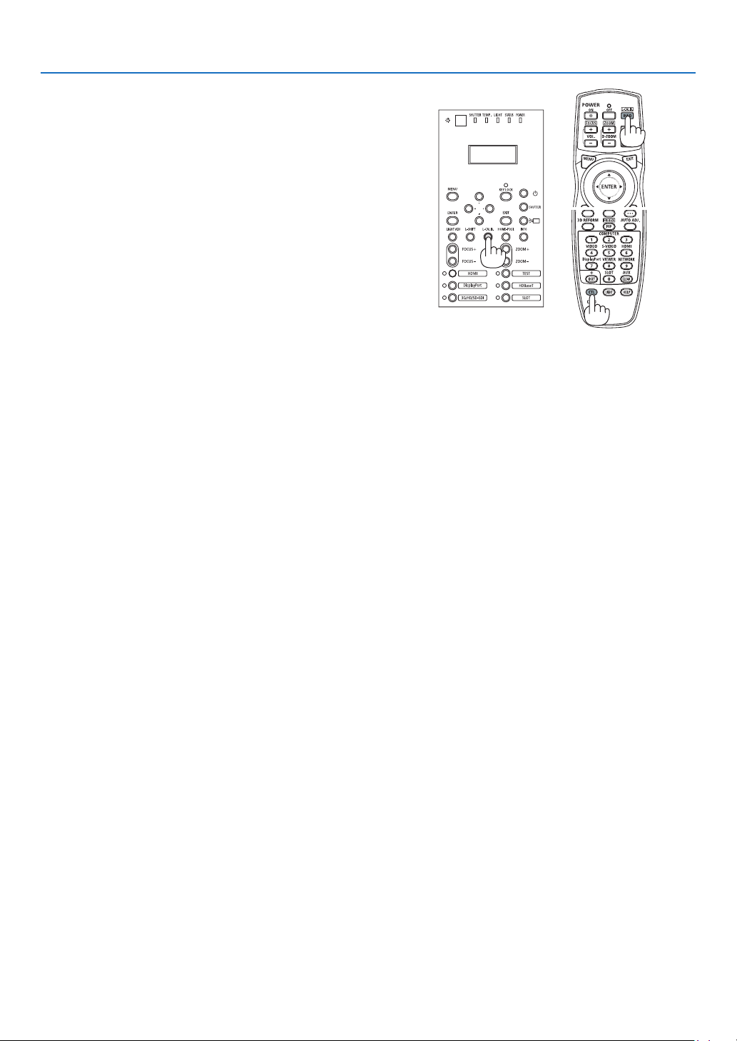
72
4. Projector Adjustment and Connecting
Performing Lens Calibration
•AfterinstallingthelensunitL4K-11ZM/L4K-15ZM/L4K-
20ZM(soldseparately),presstheL-CALIB.buttononthe
projector, or hold down the CTL button on the remote control
thenpresstheINFO/L-CALIB.buttontocarryout[LENS
CALIBRATION].
Bycarryingout[LENSCALIBRATION],theadjustment
rangeofthezoomofthe[LENSMEMORY]iscalibrated.
If you need to install or replace the lens unit, contact your
distributor and have them do it for you.
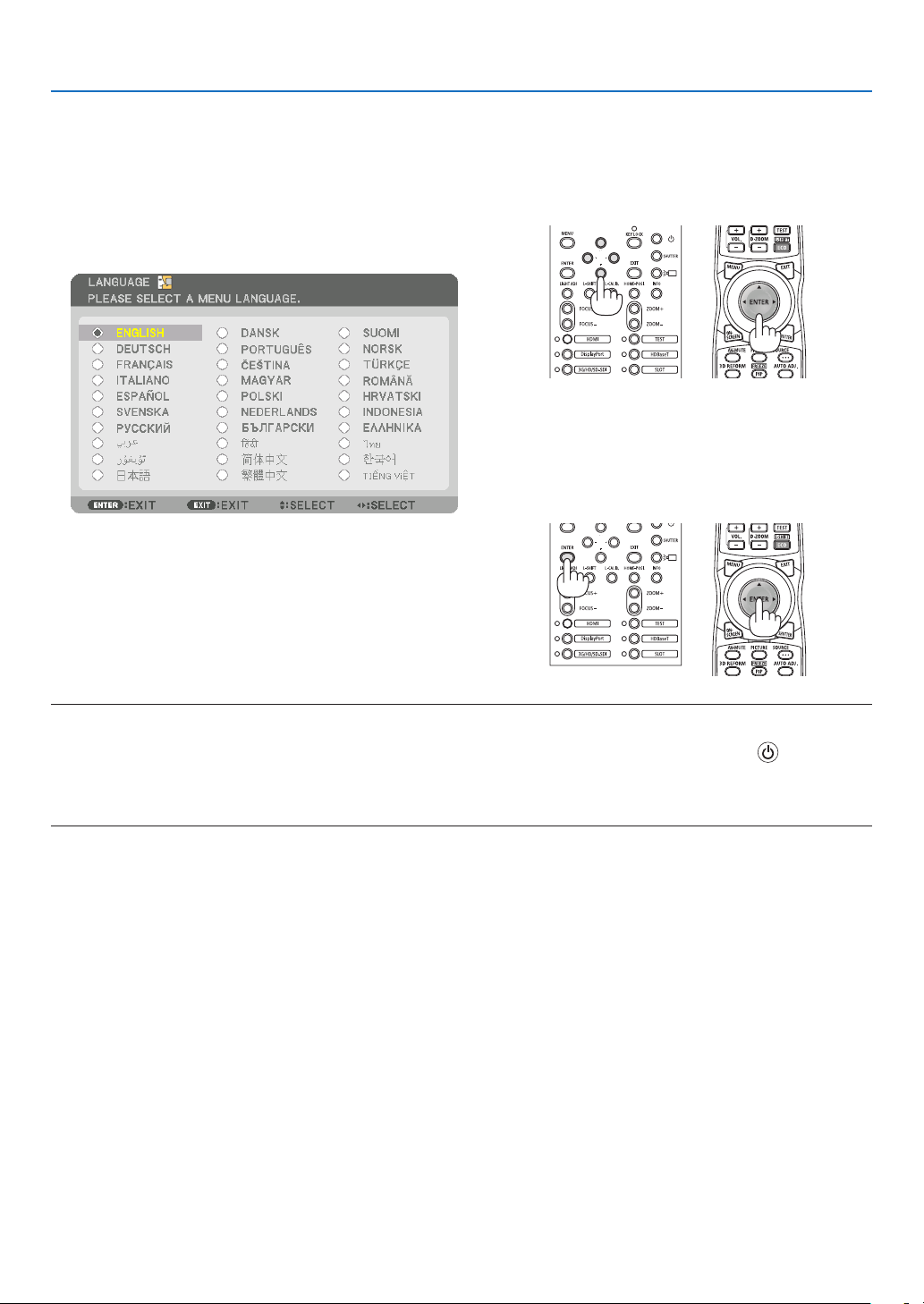
73
4. Projector Adjustment and Connecting
Note on Startup screen (Menu Language Select screen)
When you rst power on the projector, you will get the Startup menu. This menu gives you the opportunity to select
one of the 30 menu languages.
To select a menu language, follow these steps:
1. Use the ▲, ▼, ◀ or ▶ button to select one of the 30
languages from the menu.
2. Press the ENTER button to execute the selection.
After this has been done, you can proceed to the menu
operation.
If you want, you can select the menu language later.
NOTE:
•Ifthemessage,[PLEASESET"DATEANDTIME".]isshown,pleasesetthecurrentdateandtime.
•WhentheKEYLOCKindicatorisashing,thatmeans[CONTROLPANELLOCK]hasbeensetandpressingthebuttonwillnot
causetheunittopower-on.Release[CONTROLPANELLOCK].
•WhilethePOWERindicatorisblinkinggreeninshortcycles,thepowercannotbeturnedoffbyusingthepowerbutton.(While
thePOWERindicatorisblinkinggreeninlongcycles,the[OFFTIMER]isfunctionedandthepowercanbeturnedoff.)
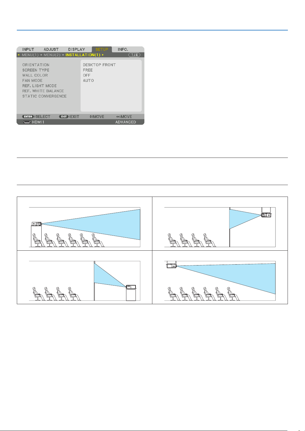
74
4. Projector Adjustment and Connecting
4-3. Selecting the projector orientation
This reorients your image for your type of projection. Select [SETUP] →[INSTALLATION(1)]→[ORIENTATION]in
the on-screen menu. The options are: desktop front projection, ceiling rear projection, desktop rear projection, and
ceiling front projection.
NOTE:
•Pleaseconsultthedistributorifyourequirespecialinstallationservicese.g.whenmountingtheprojectortoaceilingorsuspend-
ingfromtheceilingusingeyebolts.Neverinstalltheprojectoronyourown.Thismayresultintheprojectorfallingdownand
causinginjurytopeople.
DESKTOPFRONTCEILING REAR
DESKTOPREARCEILINGFRONT
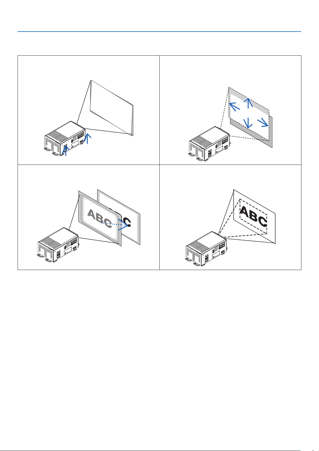
75
4. Projector Adjustment and Connecting
4-4. Adjusting the Picture Size and Position
Adjusting the projector’s settings
[Level adjuster]
(→ page 76)
Adjusting the projected image’s vertical and horizontal
position
[Lens shift]
(→ page 77)
Adjusting the focus
[Focus]
(→ page 79)
Finely adjusting the size of an image
[Zoom]
(→ page 81)
In this chapter drawings and cables are omitted for clarity.
TIP:
•Built-intestpatternscanbeconvenientlyusedforadjustingthepicturesizeandposition.
ApressoftheTESTbuttonwilldisplaythetestpattern.The◀or▶buttoncanselectonetestpattern.Toclosethetestpattern,
changethesourcetoanother.
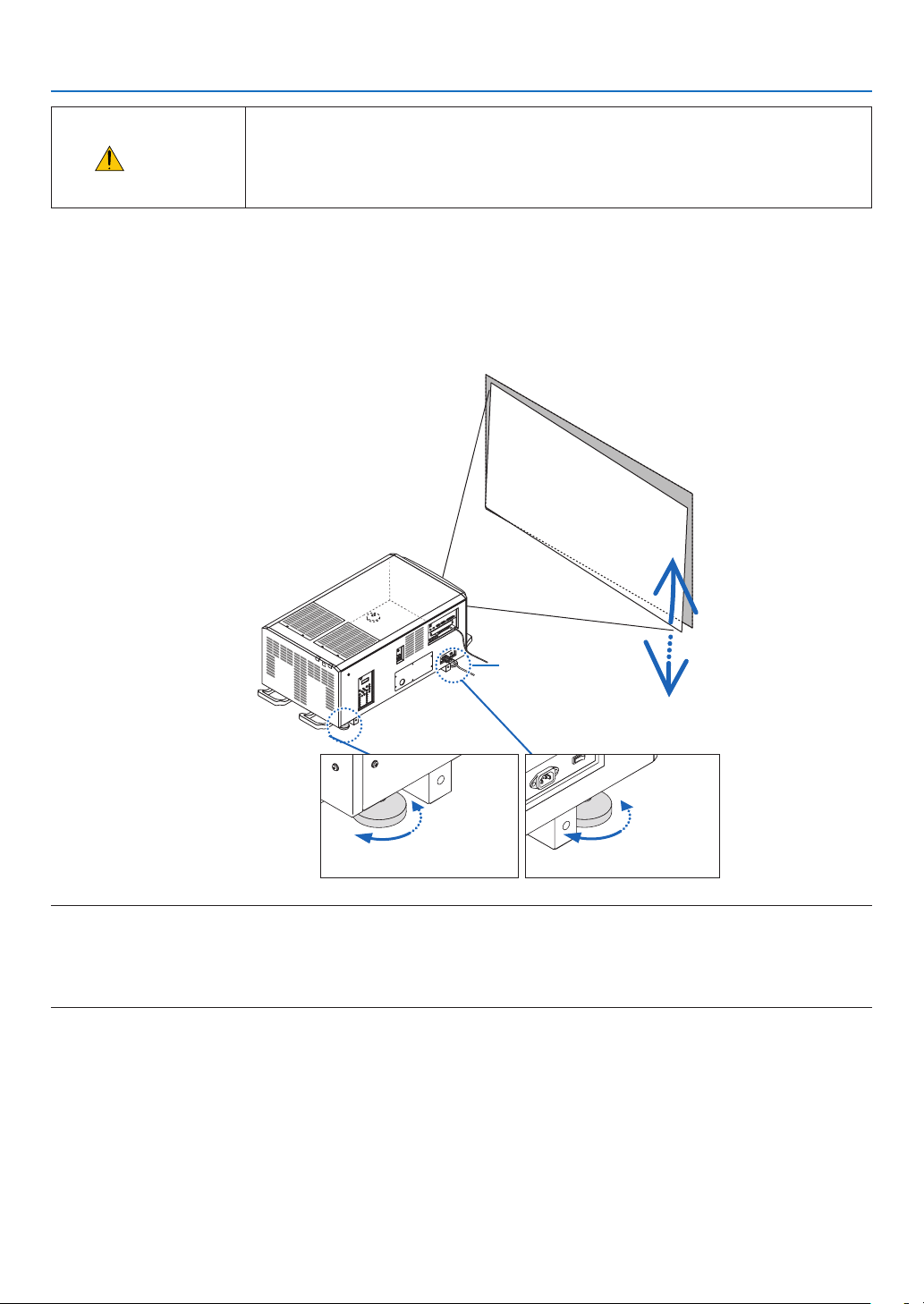
76
4. Projector Adjustment and Connecting
CAUTION
•Performtheadjustmentfrombehindorfromthesideoftheprojector.Adjustingfrom
the front could expose your eyes to strong light which could injure them.
•Keephandsawayfromthelensmountingportionwhilethelensshiftisinoperation.
Failure to do so could result in hands being pinched by the moving lens.
4-4-1. Adjustment of the projector’s settings (Level adjusters)
The projector must be placed square to the screen otherwise keystone distortion may appear on the screen. For
setting the projector perpendicular to the screen when viewed from the side, utilizing the level adjusters equipped at
eachcorneroftheprojectorbottom.MaximumAdjustablelengthoftheleveladjusteris10mm/0.39".
Example for adjustment
Raise Raise
Lower Lower
Level adjuster
NOTE:
•Donotlengtheneachoftheleveladjustersanymorethan10mm/0.39".Theforceofdoingsomaycausetheleveladjusterto
comeoff,resultingindamagetotheprojector.
•Payattentiontolengthenorshortentwoleveladjustersatfrontatthesametime.Samefortherearadjusters,otherwise,the
weightoftheprojectorisloadedononeleveladjusteranditmaycauseofdamagetoit.
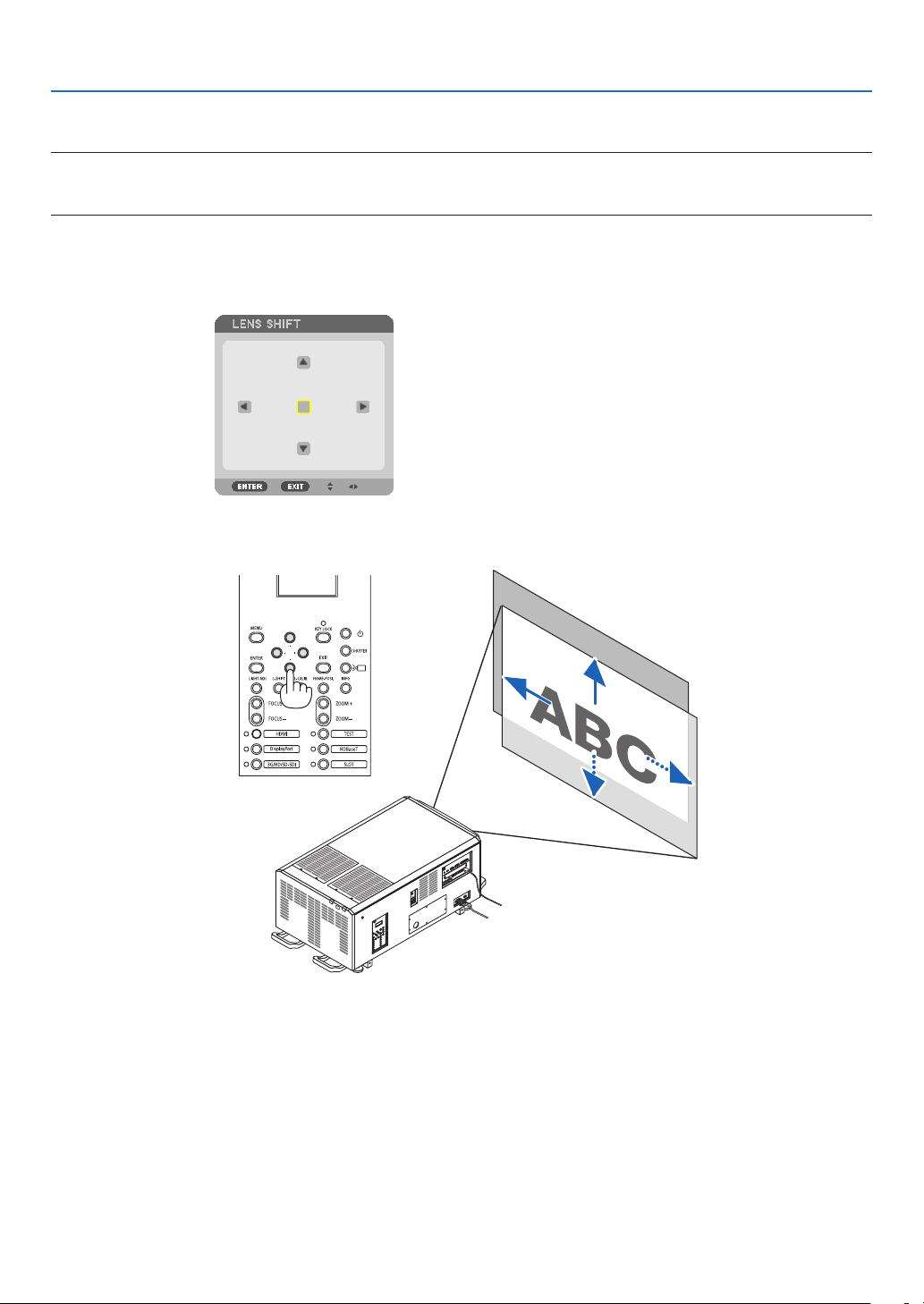
77
4. Projector Adjustment and Connecting
4-4-2. Adjusting the vertical position of a projected image (Lens shift)
NOTE:
•Shiftingthelenstothemaximumintwodirectionscombinedwillcausetheedgesoftheimagetobecomedarkorwillcause
someshadows.
Adjusting with buttons on the cabinet
1. Press the L-SHIFT button.
The [LENS SHIFT] screen will be displayed.
2. Press the ▼▲◀ or ▶ button.
Use the ▼▲◀▶ buttons to move the projected image.
•Returningthelensshiftpositiontothehomeposition
Press the HOME-POSI. button to return the lens shift position to the home position (nearly center position)
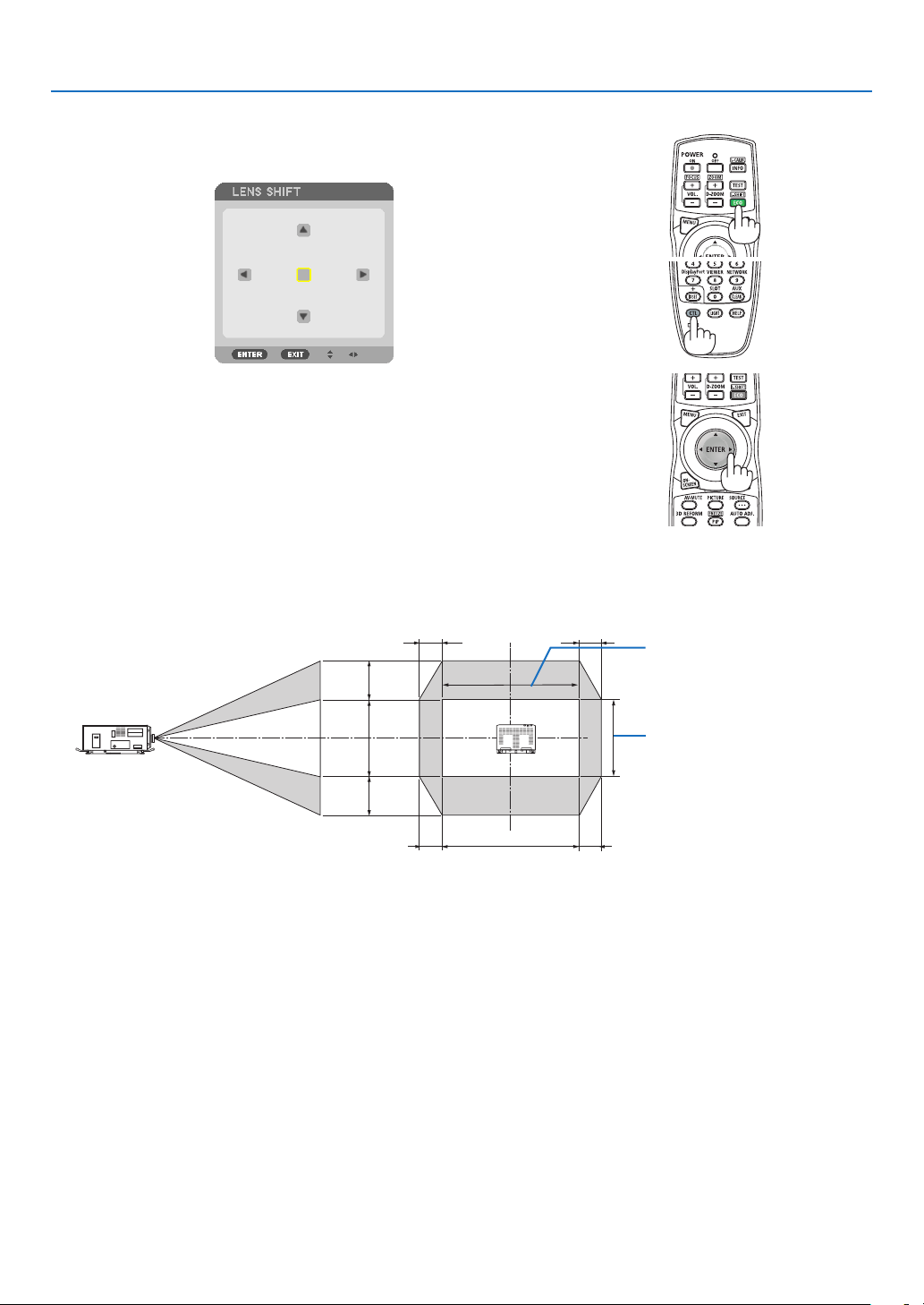
78
4. Projector Adjustment and Connecting
Adjusting with the remote control
1. Hold the CTL button and press the ECO/L-SHIFT button.
The [LENS SHIFT] screen will be displayed.
2. Press the ▼▲◀ or ▶ button.
Use the ▼▲◀▶ buttons to move the projected image.
TIP:
•Thegurebelowshowsthelensshiftranges(projectionmode:desktop/front)for3840×2160images(16:9aspectratio)forthe
L4K-11ZM,L4K-15ZMandL4K-20ZMlensunits.Seepage10forthedetailsofotherlenses.
100%V
55%V
55%V
100%H
22%H 22%H
22%H22%H
Height of projected image
Width of projected image
Descriptionofsymbols:Vindicatesvertical(heightoftheprojectedimage),Hindicateshorizontal(widthoftheprojectedimage).
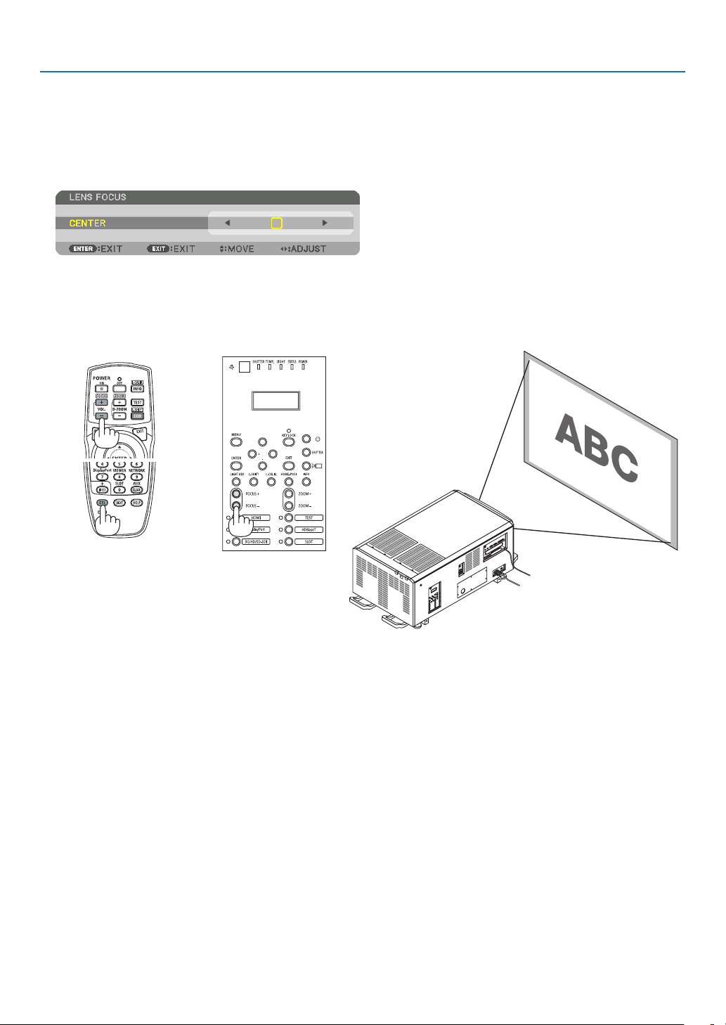
79
4. Projector Adjustment and Connecting
4-4-3. Focus
FortheL4K-11ZM,L4K-15ZMandL4K-20ZMlensunits,performtheimagesurfaceadjustmentbeforeadjustingthe
focus. (→ next page)
1. Press the FOCUS +/− button.
The FOCUS adjustment bar will be displayed on.
The focus is adjusted.
•Ontheremotecontrol,whilepressingontheCTLbutton,pressonVOL/FOCUS(+)or(−)button.
•◀ or ▶ buttons on the cabinet or the remote control are also available to adjust FOCUS while the FOCUS
adjustment bar is displayed on.
TIP:Toobtainthebestfocus,performthefollowing(forxedinstallation)
Preparation:Warmuptheprojectorforonehour.
1.UsetheFOCUS+/−buttonstomakesureyouobtainthebestfocus.Ifyoudonot,movetheprojectorbackandforth.
2.PresstheTESTbuttonontheremotecontroltodisplaythetestpattern.
3.KeeppressingtheFOCUS−buttonuntilthegridofthetextpatternismadeinvisible.
4.KeeppressingtheFOCUS+buttonuntilyouobtainthebestfocus.
Ifyouadjustbeyondthebestfocalpoint,gobacktostep3andrepeattheprocedures.
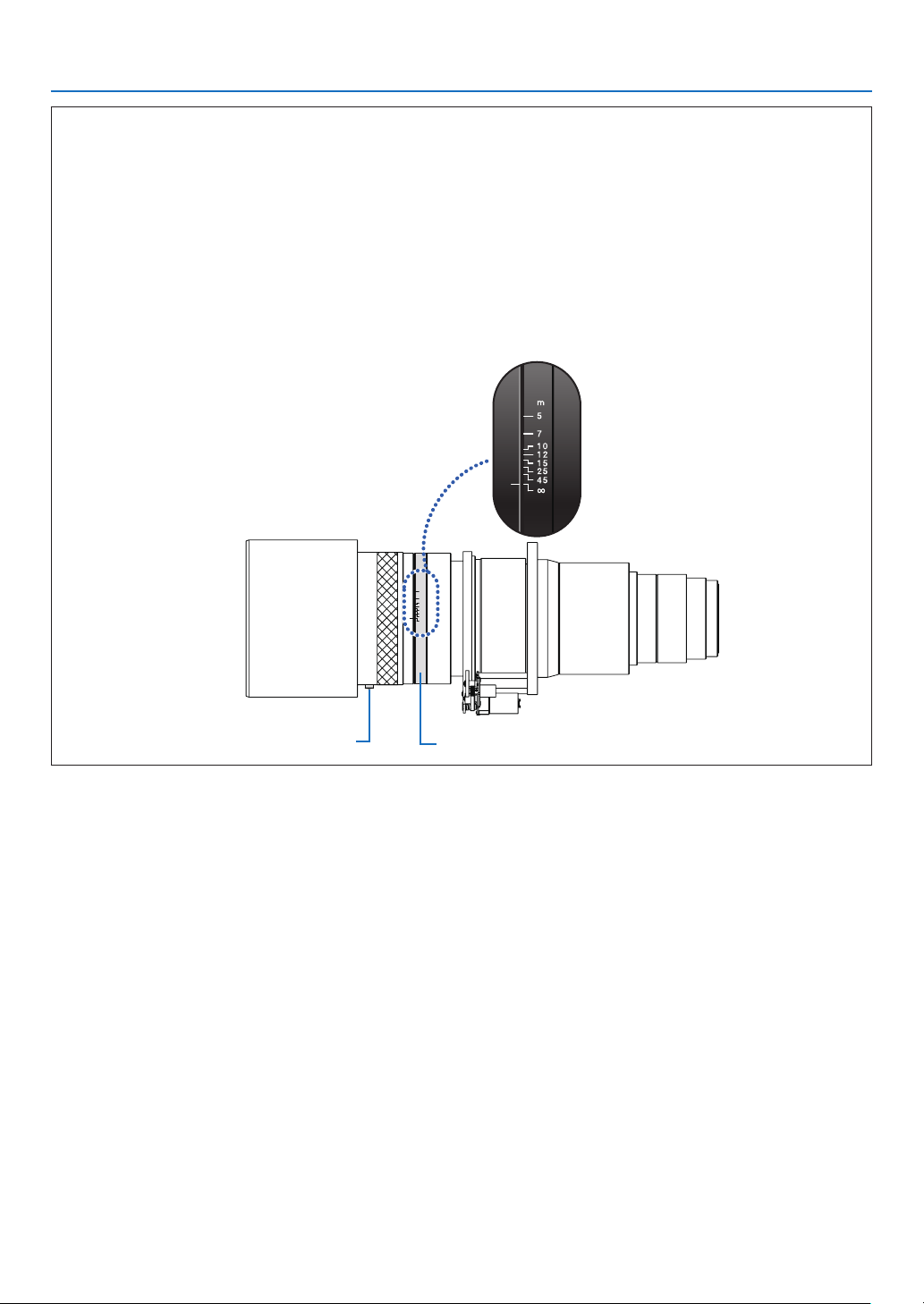
80
4. Projector Adjustment and Connecting
Lens image surface adjustment
(Applicable lens units: L4K-11ZM, L4K-15ZM and L4K-20ZM)
WhenusingtheL4K-11ZM,L4K-15ZMorL4K-20ZMlensunits,performtheimagesurfaceadjustmentbefore
adjusting the lens' focus.
Adjustment procedure
1. Loosen the lock bolt.
2.
Set the dial to the value of the projection distance.
Example:Iftheprojectiondistanceis20m,setthedialtobetween15and25.
3. Tighten the lock bolt.
∞
45
25
15
12
10
7
5
m
DialLock bolt
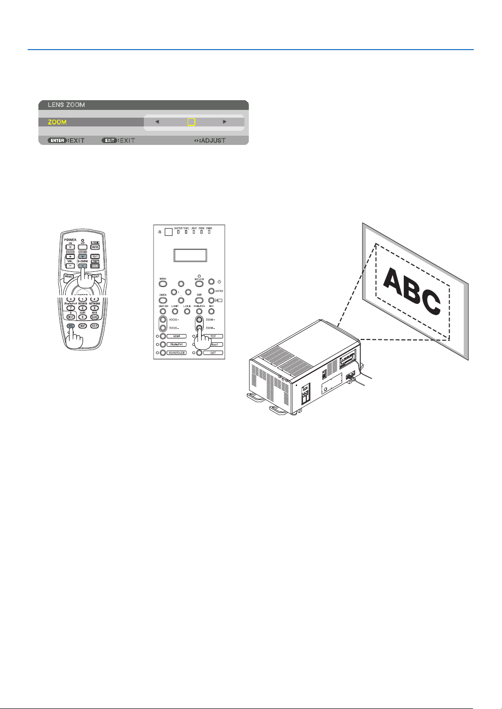
81
4. Projector Adjustment and Connecting
4-4-4. Zoom
1. Press the ZOOM +/− button.
The ZOOM adjustment bar will be displayed on.
The zoom is adjusted.
•Ontheremotecontrol,whilepressingontheCTLbutton,presstheD-ZOOM/ZOOM(+)or(−)button.
•◀ or ▶ buttons on the cabinet or the remote control are available to adjust ZOOM while the ZOOM adjustment
bar is displayed on.
•ThezoomofthelensunitL2K-10F1cannotbeadjusted.
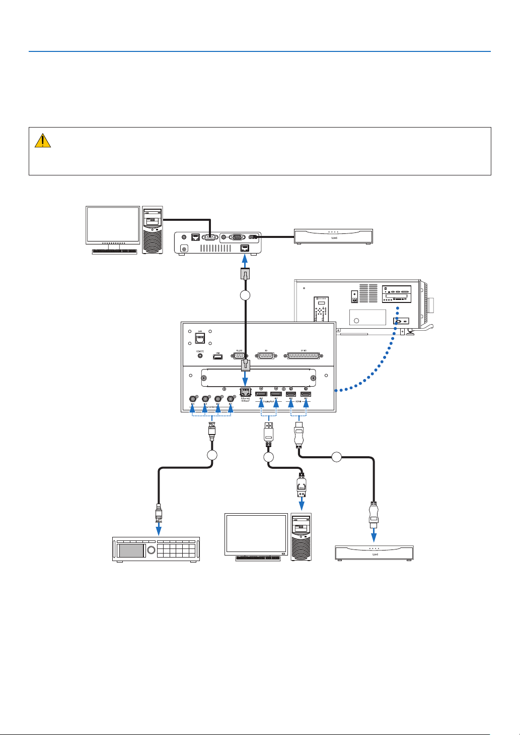
82
4. Projector Adjustment and Connecting
4-5. Connecting to Other Equipments
4-5-1. Connecting to external equipments
Below is an example of connections to external equipment.
No connection cables are included with this unit. Use the appropriate cables for the connections.
CAUTION
For HDMI, DisplayPort, BNC and LAN, please use a shielded cable.
Use of other cables may cause interference with radio and television reception.
3
4
2
1
Professionalvideoequipment,etc.Computer,etc.Blu-rayplayer,etc.
HDBaseTtransmissiondevice,etc.
83
4. Projector Adjustment and Connecting
① HDMI cable (not supplied)
•UseacertiedHighSpeedHDMI
®
Cable or High Speed HDMI
®
Cable with Ethernet.
•WhenconnectingtheHDMI1INorHDMI2INconnectoroftheprojectortotheBlu-rayplayer,theprojector'svideo
level can be made settings in accordance with the Blu-ray player's video level. In the menu select [ADJUST] →
[VIDEO]→[VIDEOLEVEL]andmakenecessarysettings.
② DisplayPort cable (not supplied)
•UseacertiedDisplayPortcable.
③ BNC cable (not supplied)
•Usecablesthatare5C-FBorhigher(5C-FB,7C-FB,etc.)orBelden1694Aorhigher.Inaddition,usecableswith
a cable length 100m or less.
•Thelengthofcablesthatcanbeusedmaydiffer,dependingonthesignal.
④ LAN cable (not supplied)
•Pleaseuseashieldedtwistedpair(STP)cableofCategory5eorhigherfortheLANcable(soldcommercially).
•TheHDBaseTportoftheprojectorsupportsHDMIsignals(HDCP)fromtransmissiondevices,controlsignalsfrom
external devices (serial, LAN) and remote control signals (IR commands).
•ThemaximumtransmissiondistanceovertheLANcableis100m.(themaximumdistanceis70mfora4Ksignal)
•Pleasedonotuseothertransmissionequipmentbetweentheprojectorandtransmissionequipment.Thepicture
quality may be degraded as a result.
•ThisprojectorisnotguaranteedtoworkwithallHDBaseTtransmissiondevicessoldcommercially.
After turning on the power of the unit, select the input according to the connection terminal.
Input connector Button on the projector
cabinet
Button on the remote
control
Note
HDMI1/2 IN HDMI HDMI Switches between HDMI1 and HDMI2 each time
it is pressed.
DisplayPort 1/2 IN DisplayPort DisplayPort •SwitchesbetweenDisplayPort1andDisplay-
Port2 each time it is pressed.
•SelectDisplayPort1forduallink.
SDI 1/2/3/4 IN 3G/HD/SD-SDI AUX •SwitchesbetweenSDI1,SDI2,SDI3andSDI4
each time it is pressed.
•SelectSDI1forquadlinkorduallink.
HDBaseT HDBaseT NETWORK—
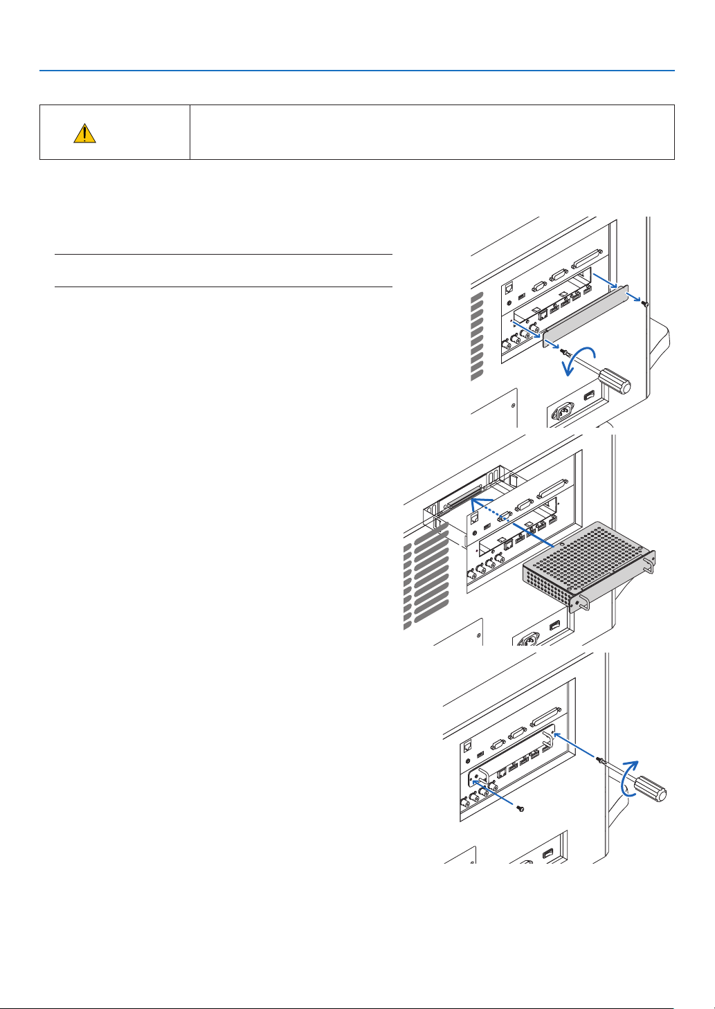
84
4. Projector Adjustment and Connecting
4-5-2. Mounting the Optional Board (sold separately)
CAUTION
•Before mounting or removing the optional board, check that the projector power
switch and light power switch of the projector is turned off. Implement the connec-
tion with AC power shut off.
Tool needed: Phillips screwdriver (plus-head)
1. Loosen the two screws on the SLOT cover of the LV unit.
Remove the two screws and the SLOT cover.
NOTE:
•Keepthetwoscrewsandtheslotcover.
2. Insert the optional board into the slot.
Make sure that the board is inserted into the slot in the correct
orientation.
Incorrect orientation may cause miscommunication between
the optional board and projector.
3. Tighten the two screws on both sides of the slot.
•Besuretotightenthescrews.
This will complete installation of the optional board.
Toselecttheoptionalboardsource,selectSLOTastheinput.
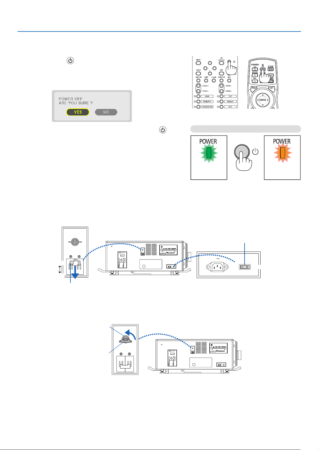
85
4. Projector Adjustment and Connecting
4-6. Turning off the Projector
To turn off the projector:
1. First, press the (POWER) button on the projector
cabinet or the POWER OFF button on the remote control.
The [POWER OFF / ARE YOU SURE ?] message will ap-
pear.
2. Secondly, press the ENTER button or press the
(POWER) or the POWER OFF button again.
WhentheprojectorisinSTANDBYMODE,thePOWER
indicator lights up orange.
•BeforethePOWERindicatorlightsuporange,the
buzzer sound is released when [NOTIFICATION SET-
TING]for[BUZZER]isON.
Power On
Steady green light
Standby
Steady orenge light
Press twice
3. After the projector enters the standby state, turn off the projector power switch ([1]), then the light power
switch ([2]).
The POWER indicator will go off and the main power will turn off.
•WhilethePOWERindicatorisblinkinggreeninshortcycles,thepowercannotbeturnedoff.
ON
ON
OFF
OFF
Light power switch
Projector power switch
4. Return the administrator switch to the OFF position, then remove the administrator key.
Administrator switch
Administrator key
5. Turn off the AC power to the projector.

86
4. Projector Adjustment and Connecting
NOTE:
•Inthefollowinginstances,donotturnofftheprojectorpowerswitchandlightpowerswitchordisconnecttheACpower.Doing
socandamagetheprojector.
•Whileprojectingimages
•Whilethepowerison
•Duringthecoolingafterthepoweristurnedoff.
•Afteryouhavemadetheadjustmentsandclosedtheadjustmentscreen,donotturnofftheprojectorpowerswitchandlight
sourcepowerswitch,orpulloutthepowerplugfromthewalloutlet,orshutdowntheACpowersupplyforabout10seconds.
TheadjustmentvaluesmaybeinitializediftheACpowersupplyisshutdownduringthistime.
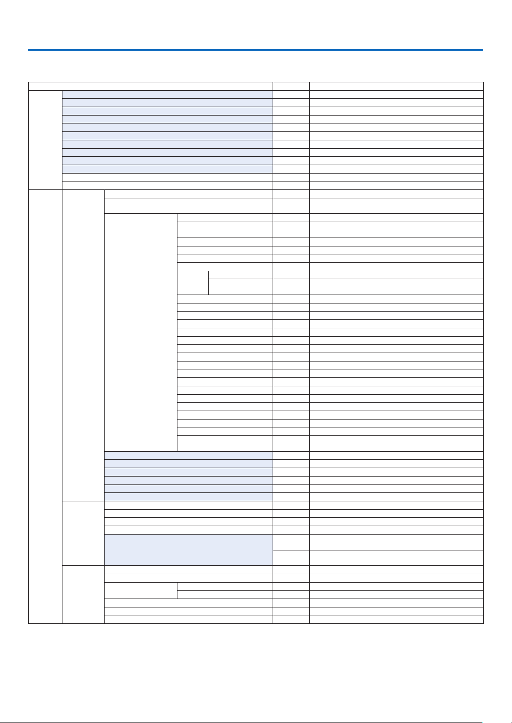
87
* The asterisk (*) indicates that the default setting varies depending on the signal.
*1The[GAMMASETTING]itemisavailablewhenanitemotherthan[DICOMSIM.]isselectedfor[REFERENCE].
*2The[SCREENSIZE]itemisavailablewhen[DICOMSIM.]isselectedfor[REFERENCE].
*3When[HIGH-BRIGHT]or[PRESENTATION]isselectedin[REFERENCE],the[COLORTEMPERATURE]isnotavailable.
5. List of Menu Items
Some menu items are not available depending on the input source.
•Basicmenuitemsareindicatedbyshadedarea.
Menu Item Default Options
INPUT
HDMI1
HDMI2
DisplayPort1
DisplayPort2
HDBaseT
SDI1
SDI2
SDI3
SDI4
SLOT
ENTRY LIST
TEST PATTERN
ADJUST
PICTURE
MODE STANDARD STANDARD, PROFESSIONAL
PRESET *
AUTO, 1:HIGH-BRIGHT, 2:PRESENTATION, 3:REC709, 4:CINEMA,
5:REC2020, 6:sRGB, 7:DICOM SIM.
DETAIL SETTINGS
GENERAL
REFERENCE *
HIGH-BRIGHT, PRESENTATION, REC709, CINEMA, REC2020,
sRGB, DICOM SIM.
GAMMA SETTING*
1
SCREEN SIZE*
2
* LARGE, MEDIUM, SMALL
COLOR TEMPERATURE*
3
*
DYNAMIC CONTRAST * OFF, MOTION IMAGE, STILL IMAGE
LIGHT
MODE
LIGHT ADJUST
CONSTANT
BRIGHTNESS
OFF OFF, ON
WHITE BALANCE
CONTRAST R 0
CONTRAST G 0
CONTRAST B 0
BRIGHTNESS R 0
BRIGHTNESS G 0
BRIGHTNESS B 0
COLOR CORRECTION
RED 0 HUE, SATURATION
GREEN 0 HUE, SATURATION
BLUE 0 HUE, SATURATION
YELLOW 0 HUE, SATURATION
MAGENTA 0 HUE, SATURATION
CYAN 0 HUE, SATURATION
COLOR SETTING
SETTINGS ON, OFF
MCGD REFERENCE, RED, GREEN, BLUE, WHITE, OK, CHANCEL
TCGD
REFERENCE, RED, GREEN, BLUE, CYAN, MAGENTA, YELLOW,
WHITE, SAVE, OK, CHANCEL
CONTRAST 50
BRIGHTNESS 50
SHARPNESS 10
COLOR 50
HUE 0
RESET
IMAGE
OPTIONS
HORIZONTAL *
VERTICAL *
BLANKING * TOP, BOTTOM, LEFT, RIGHT
OVERSCAN AUTO, 0[%], 5[%], 10[%]
ASPECT RATIO
AUTO
(HDTV/SDTV) AUTO, NORMAL, 4:3, LETTERBOX, WIDE SCREEN,
ZOOM, FULL
AUTO
(COMPUTER) AUTO, NORMAL, 4:3, 5:4, 16:9, 15:9, 16:10, FULL,
NATIVE
VIDEO
NOISE REDUCTION OFF OFF, LOW, MEDIUM, HIGH
DEINTERLACE NORMAL NORMAL, MOVIE, STILL
CONTRAST
ENHANCEMENT
MODE AUTO OFF, AUTO, NORMAL
GAIN
SIGNAL TYPE AUTO
AUTO, RGB, REC601, REC709, REC2020
VIDEO LEVEL AUTO AUTO, NORMAL, ENHANCED, SUPER WHITE
HDR MODE AUTO AUTO, OFF, ON

88
5. List of Menu Items
Menu Item Default Options
ADJUST
3D
SETTINGS(1)
STEREO VIEWER SINGLE SINGLE, DUAL LEFT, DUAL RIGHT
FORMAT AUTO
AUTO, OFF(2D), FRAME PACKING, SIDE BY SIDE (HALF), SIDE BY
SIDE (FULL), TOP AND BOTTOM
3D
SETTINGS(2)
3D DETAIL SETTINGS OFF OFF, ON
L/R DISPLAY REF. NOT USE NOT USED, USE GPI(TRUE), USE GPI(INVERT)
DELAY
TIME
PHASE
FRAME RATE RATIO 1:1 1 : 1, 4 : 1, 6 : 1, 2 : 2, 4 : 2, 6 : 2
INPUT FRAME DOMINANCE
LEFT(L1R1
L2R2)
LEFT(L1R1 L2R2), RIGHT(R1L1 R2L2)
L/R OUTPUT REF. POLARITY TRUE TRUE, INVERT
DARK TIME
L/R INPUT REF.
USE
PORT(TURE)
NONE PROVIDED, USE GPI(TRUE), USE GPI(INVERT),
USE PORT(TURE), USE PORT(INVERT)
LENS
MEMORY
STORE
MOVE
RESET
LOAD BY SIGNAL OFF OFF, ON
FORCED MUTE OFF OFF, ON
DISPLAY
PICTURE BY
PICTURE
MODE OFF OFF, DUAL, QUAD
SUB1 INPUT
SDI1, SDI2, SDI3, SDI4, HDMI1, HDMI2, DisplayPort1,
DisplayPort2, HDBaseT, SLOT
SUB2 INPUT
SDI1, SDI2, SDI3, SDI4, HDMI1, HDMI2, DisplayPort1,
DisplayPort2
SUB3 INPUT
SDI1, SDI2, SDI3, SDI4, HDMI1, HDMI2, DisplayPort1,
DisplayPort2
PORTRAIT ANGLE 0° 0°, 90°, 270°
MAIN POSITION
SUB POSITION
GEOMETRIC
CORRECTION
MODE OFF
OFF, KEYSTONE, CORNERSTONE, HORIZONTAL CORNER,
VERTICAL CORNER, WARP, PC TOOL
KEYSTONE
HORIZONTAL
VERTICAL
TILT
THROW RATIO
CORNERSTONE
TOP-LEFT, TOP, TOP-RIGHT, LEFT, RIGHT, BOTTOM-LEFT,
BOTTOM, BOTTOM-RIGHT
HORIZONTAL CORNER
TOP-LEFT, TOP, TOP-RIGHT, LEFT, RIGHT, BOTTOM-LEFT,
BOTTOM, BOTTOM-RIGHT
VERTICAL CORNER
TOP-LEFT, TOP, TOP-RIGHT, LEFT, RIGHT, BOTTOM-LEFT,
BOTTOM, BOTTOM-RIGHT
WARP
TOP-LEFT, TOP, TOP-RIGHT, LEFT, RIGHT, BOTTOM-LEFT,
BOTTOM, BOTTOM-RIGHT
PC TOOL OFF OFF, 1, 2, 3
RESET
EDGE
BLENDING
MODE OFF OFF, ON
MARKER OFF OFF, ON
TOP
CONTROL OFF OFF, ON
RANGE
POSITION
BOTTOM
CONTROL OFF OFF, ON
RANGE
POSITION
LEFT
CONTROL OFF OFF, ON
RANGE
POSITION
RIGHT
CONTROL OFF OFF, ON
RANGE
POSITION
BLEND CURVE 5 OFF, 1, 2, 3, 4, 5, 6, 7, 8, 9
BLACK LEVEL
CENTER
REFERENCE, RED, GREEN, BLUE, RESET
TOP
BOTTOM
LEFT
RIGHT
BORDER(TOP)
BORDER(BOTTOM)
BORDER(LEFT)
BORDER(RIGHT)
89
5. List of Menu Items
Menu Item Default Options
DISPLAY
PICTURE
SETTING
MODE OFF OFF, ZOOM
ZOOM
HORIZONTAL ZOOM
VERTICAL ZOOM
HORIZONTAL POSITION
VERTICAL POSITION
TILING
WIDTH
HEIGHT
HORIZONTAL POSITION
VERTICAL POSITION
MULTI
SCREEN
WHITE BALANCE
MODE
CONTRAST W
CONTRAST R
CONTRAST G
CONTRAST B
BRIGHTNESS W
BRIGHTNESS R
BRIGHTNESS G
BRIGHTNESS B
SETUP
MENU(1)
LANGUAGE ENGLISH
ENGLISH, DEUTSCH, FRANÇAIS, ITALIANO, ESPAÑOL, SVENSKA,
日本語
DANSK, PORTUGUÊS, ČEŠTINA, MAGYAR, POLSKI,
NEDERLANDS, SUOMI
NORSK, TÜRKÇE, РУССКИЙ,
, Ελληνικά, 简体中文, 한국어
ROMÂNĂ, HRVATSKA, БЪЛГАРСКИ, INDONESIA, , ไทย,
, 繁體中文, Tiếng Việt
COLOR SELECT COLOR COLOR, MONOCHROME
INPUT DISPLAY ON OFF, ON
MESSAGE DISPLAY ON OFF, ON
ID DISPLAY OFF OFF, ON
3D CAUTION MESSAGE ON OFF, ON
DISPLAY TIME
AUTO 45
SEC
MANUAL, AUTO 5 SEC, AUTO 15 SEC, AUTO 45 SEC
FILTER MESSAGE OFF
OFF, 100[H], 500[H], 1000[H], 2000[H], 5000[H], 10000[H],
20000[H]
MENU(2)
MENU ANGLE 0° 0°, 90°, 270°
MENU POSITION CENTER
TOP-LEFT, TOP-CENTER, TOP-RIGHT, CENTER-LEFT, CENTER,
CENTER-RIGHT, BOTTOM-LEFT, BOTTOM-CENTER, BOTTOM-
RIGHT
INSTALLA-
TION(1)
ORIENTATION
DESKTOP
FRONT
DESKTOP FRONT, CEILING REAR, DESKTOP REAR, CEILING
FRONT
SCREEN TYPE FREE FREE, 4:3 SCREEN, 16:9 SCREEN, 16:10 SCREEN
WALL COLOR OFF
OFF, WHITEBOARD, BLACKBOARD, BLACKBOARD (GRAY), LIGHT
YELLOW, LIGHT GREEN, LIGHT BLUE, SKY BLUE, LIGHT ROSE,
PINK
FAN MODE AUTO AUTO, HIGH, LOW
REF. LIGHT MODE
REF. LIGHT ADJUST
CONSTANT BRIGHTNESS OFF OFF, ON
REF. WHITE BALANCE
CONTRAST R
CONTRAST G
CONTRAST B
BRIGHTNESS R
BRIGHTNESS G
BRIGHTNESS B
UNIFORMITY R
UNIFORMITY B
STATIC CONVERGENCE
HORIZONTAL R
HORIZONTAL G
HORIZONTAL B
VERTICAL R
VERTICAL G
VERTICAL B
INSTALLA-
TION(2)
SHUTTER SETTINGS
POWER ON SHUTTER OPEN OPEN, CLOSE
PICTURE MUTE SHUTTER OPEN OPEN, CLOSE
FADE IN TIME 0–10 SEC
FADE OUT TIME 0–10 SEC
REF. LENS MEMORY
PROFILE 1 1, 2
STORE
MOVE
RESET
LOAD BY SIGNAL OFF OFF, ON
FORCED MUTE OFF OFF, ON
LENS POSITION HOME
LENS CALIBRATION
90
5. List of Menu Items
Menu Item Default Options
SETUP CONTROL
TOOLS
ADMINISTRA-
TOR MODE
MENU MODE ADVANCED ADVANCED, BASIC
NOT SAVE SETTING VALUES OFF OFF, ON
NEW PASSWORD
CONFIRM PASSWORD
PROGRAM
TIMER
ENABLE OFF OFF, ON
SETTINGS
EDIT
ACTIVE OFF OFF, ON
DAY SUN
SUN, MON, TUE, WED, THU, FRI, SAT, MON-FRI, MON-SAT,
EVERY DAY
TIME
FUNCTION POWER POWER, INPUT
ADVANCED
SETTINGS
POWER OFF OFF, ON
INPUT HDMI1
HDMI1, HDMI2, DisplayPort1, DisplayPort2, HDBaseT, SDI1, SDI2,
SDI3, SDI4, SLOT
REPEAT OFF OFF, ON
DELETE
UP
DOWN
BACK
DATE AND TIME
SETTINGS
TIME
ZONE
SETTIMGS
UTC
-12:00, -11:30, -11:00, -10:30, -10:00, -09:30, -09:00, -08:30,
-08:00, -07:30, -07:00, -06:30, -06:00, -05:30, -05:00, -04:30,
-04:00, -03:30, -03:00, -02:30, -02:00, -01:30, -01:00, -00:30,
00:00, +00:30, +01:00, +01:30, +02:00, +02:30, +03:00, +03:30,
+04:00, +04;30, +05:00, +05:30, +06:00, +06:30, +07:00, +07:30,
+08:00, +08:30, +09:00, +09:30, +10:00, +10:30, +11:00, +11:30,
+12:00, +12:30, +13:00
DATE
AND TIME
SETTINGS
DATE MM/DD/YYYY
TIME HH:MM
INTERNET TIME
SERVER
OFF, ON
IP ADDRESS
UPDATE
SUMMER
TIME
SETTINGS
ENABLE OFF, ON
MON(START) 1, 2, 3, 4, 5, 6, 7, 8, 9, 10, 11, 12
DAY(START)
FIRST WEEK, SECOND WEEK, THIRD WEEK, FOURTH WEEK, LAST
WEEK
SUN, MON, TUE, WED, THU, FRI, SAT
TIME(START)
MON(EXIT) 1, 2, 3, 4, 5, 6, 7, 8, 9, 10, 11, 12
DAY(EXIT)
FIRST WEEK, SECOND WEEK, THIRD WEEK, FOURTH WEEK, LAST
WEEK
SUN, MON, TUE, WED, THU, FRI, SAT
TIME(EXIT)
TIME DIFFERENCE +01:00, +00:30, -00:30, -01:00
CONTROL PANEL LOCK OFF OFF, ON
NOTIFICATION SETTINGS
REAR LED ON OFF, ON
BUZZER ON OFF, ON
SECURITY OFF OFF, ON
COMMUNICATION SPEED 38400bps 4800bps, 9600bps, 19200bps, 38400bps, 115200bps
CONTROL ID
CONTROL ID NUMBER 1 1–254
CONTROL ID OFF OFF, ON
REMOTE SENSOR
FRONT/
BACK
FRONT/BACK, FRONT, BACK, HDBaseT
91
5. List of Menu Items
Menu Item Default Options
SETUP
NETWORK
SETTINGS
WIRED LAN
INTERFACE LAN, HDBaseT
PROFILES PROFILE 1, PROFILE 2
DHCP OFF, ON
IP ADDRESS
SUBNET MASK
GATEWAY
AUTO DNS OFF, ON
DNS CONFIGURATION
RECONNECT
PROJECTOR NAME PROJECTOR NAME PJ-********
DOMAIN
HOST NAME pj-********
DOMAIN NAME
ALERT MAIL
ALERT MAIL OFF, ON
HOST NAME pj-********
DOMAIN NAME
SENDER'S ADDRESS
SMTP SERVER NAME
RECIPIENT'S ADDRESS 1
RECIPIENT'S ADDRESS 2
RECIPIENT'S ADDRESS 3
TEST MAIL
NETWORK SERVICE
HTTP
SERVER
NEW PASSWORD
CONFIRM PASSWORD
PJLink
NEW PASSWORD
CONFIRM PASSWORD
CLASS CLASS1, CLASS2
DESTINATION
AMX BEACON OFF, ON
Extron XTP OFF, ON
SOURCE
OPTIONS(1)
DEFAULT INPUT SELECT LAST
LAST, AUTO, HDMI1, HDMI2, DisplayPort1, DisplayPort2,
HDBaseT, SDI1, SDI2, SDI3, SDI4, SLOT
SEAMLESS SWITCHING OFF OFF, ON
BACKGROUND BLUE BLUE, BLACK, LOGO
EDID VERSION
HDMI1 MODE2 MODE1, MODE2
HDMI2 MODE2 MODE1, MODE2
HDCP VERSION
HDMI1 HDCP2.2 HDCP2.2, HDCP1.4
HDMI2 HDCP2.2 HDCP2.2, HDCP1.4
HDBaseT HDCP1.4 HDCP2.2, HDCP1.4
SOURCE
OPTIONS(2)
SDI LINK SINGLE, QUAD, QUAD (2SI), DUAL
DP LINK SINGLE, DUAL
POWER
OPTIONS
DIRECT POWER ON OFF OFF, ON
AUTO POWER ON SELECT OFF
OFF, HDMI1, HDMI2, DisplayPort1, DisplayPort2, HDBaseT, SDI1,
SDI2, SDI3, SDI4, SLOT
AUTO POWER OFF OFF OFF, 0:05, 0:10, 0:15, 0:20, 0:30, 1:00
OFF TIMER OFF OFF, 0:30, 1:00, 2:00, 4:00, 8:00, 12:00, 16:00
SLOT POWER
PROJECTOR ON ON OFF, ON
PROJECTOR STANDBY ENABLE DISABLE, ENABLE
RESET
CURRENT SIGNAL
ALL DATA
ALL DATA (INCLUDING ENTRY LIST)
CLEAR FILTER HOURS
92
5. List of Menu Items
Menu Item Default Options
INFO.
USAGE TIME
LIGHT HOURS USED
FILTER HOURS USED
LOW FAN MODE HOURS USED
SOURCE(1)
INPUT TERMINAL
RESOLUTION
HORIZONTAL FREQUENCY
VERTICAL FREQUENCY
SYNC POLARITY
SCAN TYPE
SOURCE NAME
ENTRY NO.
SOURCE(2)
SIGNAL TYPE
BIT DEPTH
VIDEO LEVEL
3D FORMAT
WIRED LAN(1)
NETWORK INTERFACE
IP ADDRESS
SUBNET MASK
GATEWAY
MAC ADDRESS
DNS
WIRED LAN(2)
NETWORK INTERFACE
IP ADDRESS
SUBNET MASK
GATEWAY
MAC ADDRESS
DNS
VERSION(1)
FIRMWARE
DATA
FIRMWARE2
OTHERS
DATE TIME
PROJECTOR NAME
MODEL NO.
SERIAL NUMBER
CONTROL ID*
4
LENS ID
CONDITIONS
INTAKE TEMPERATURE1
INTAKE TEMPERATURE2
INTAKE TEMPERATURE3
INTAKE TEMPERATURE4
ATMOSPHERIC PRESSURE
ACIN VOLTAGE
HDBaseT
SIGNAL QUALITY
OPERATION MODE
LINK STATUS
HDMI STATUS
*4[CONTROLID]willbedisplayedwhen[CONTROLID]hasbeensetup.
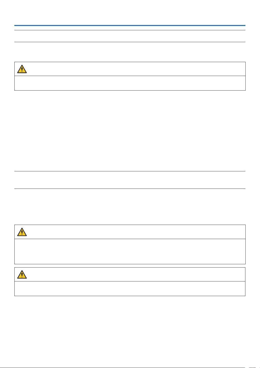
93
6. Maintenance
NOTE
•
Pleaserequestyourdistributortoperformcleaningoftheprojectorinside.
6-1. Cleaning the Cabinet
WARNING
•Please do not use a spray containing ammable gas to remove dust attached to the cabinet, etc. Doing so may
result in res.
Be sure to always check that the AC power supply of the projector is disconnected before carrying out maintenance
of the projector.
•Wipe with a dry, soft cloth without nap.
When the cabinet is excessively dirty, wipe with cloth well wrung after being dampened with a neutral detergent
diluted with water and then nish up with a dry cloth.
When you use a chemical dust cloth, follow the instructions in the manual attached to it.
•Do not use a solvent, such as thinner or benzene. The coating may deteriorate or peel off.
•When removing dust on the ventilation opening, suck it off using an adapter with a brush on a vacuum cleaner.
Never allow the cleaner without an adapter to come into direct contact or use a nozzles adapter in cleaning.
•Clean the ventilation opening at regular intervals. Dust, if allowed to accumulate there, may cause heating inside,
which leads to functional trouble. The interval, which can vary with the location of your projector, is about 100 hours.
•Do not damage the cabinet by scratching it or allowing hard objects to hit it. This can scratch the projector.
•Consult your dealer/distributor about cleaning the inside of the projector.
NOTE
•
Donotallowinsecticideorothervolatileliquidtosplashonthecabinet,lensorscreen.Also,donotallowanyrubberorplastic
objecttoremainincontactwiththecabinetforalongtime.Thecoatingmaydeteriorateorpeeloff.
6-2. Cleaning the Lens
Clean the lens the same way as with camera lens (using a commercially available camera blower or cleaning paper
for glasses). Take care not to damage the lens when cleaning.
WARNING
•Do not look into the light source while the proj
ectorisON.Stronglightisemittedfromtheprojectorand visual
impairment could result.
•Please do not use a spray containing ammable gas to remove dust attached to the lens, etc. Doing so may
result in res.
CAUTION
•Before cleaning the lens, rst turn off the power, make sure the cooling fan has completely stopped, then turn
off the AC power. Make sure the unit has cooled down completely before cleaning the lens.
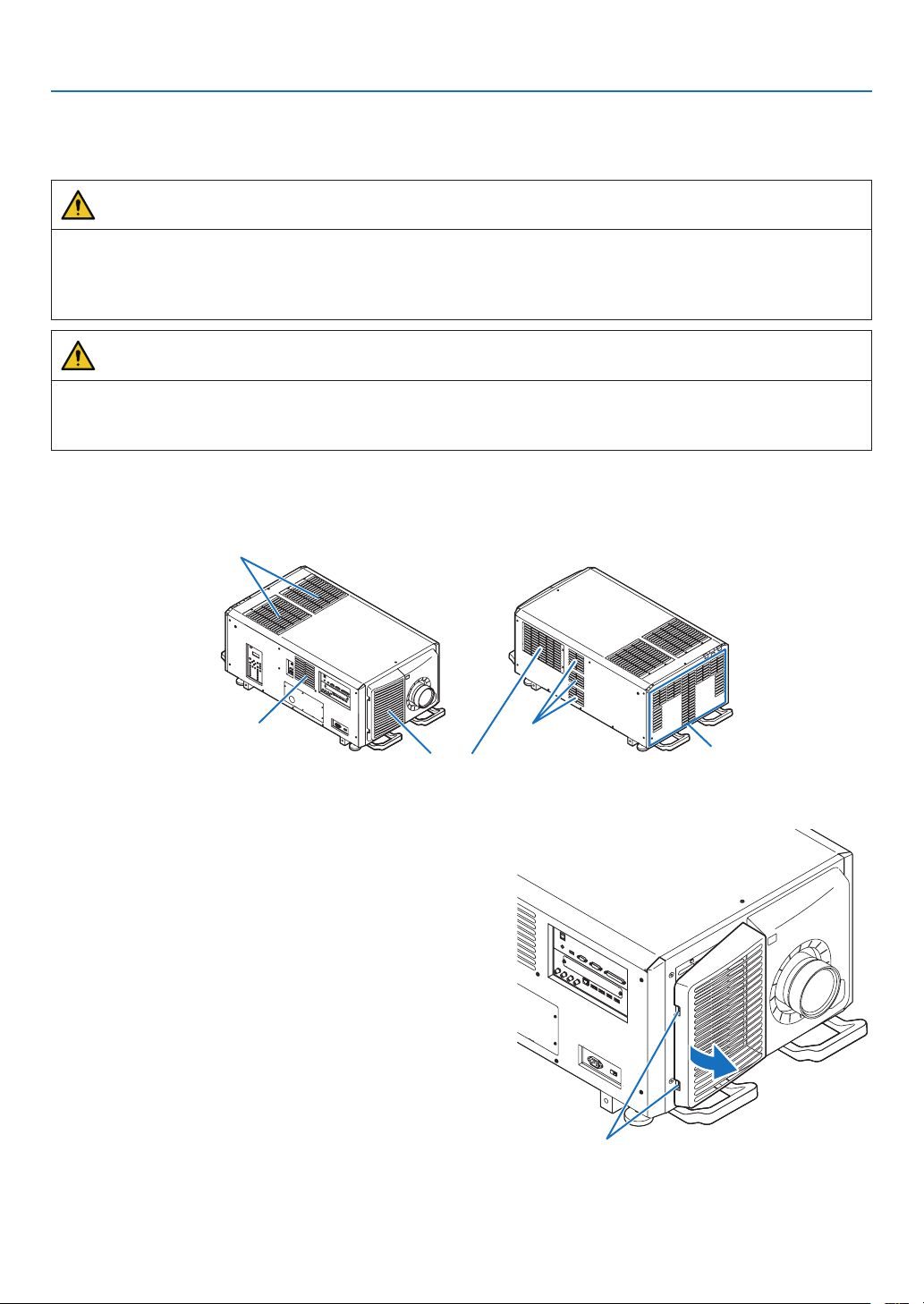
94
6. Maintenance
6-3. Cleaning the Air Filters
Air lters are attached over the air inlet of the projector to prevent dust. The air lters should be cleaned periodically
in order to maintain projector performance.
WARNING
•Dust in air lters will hinder ventilation of the projector, lead to a rise of the internal temperature and can cause
a re or malfunction.
•Please do not use a spray containing ammable gas to remove dust attached to the lters, etc. Doing so may
result in res.
CAUTION
•Before cleaning the lter, rst turn off the power, make sure the cooling fan has completely stopped, then turn
off the AC power. Make sure the unit has cooled down completely before cleaning the lter. Removing the lter
cover while the unit is running could result in burns or electric shock from contact with internal parts.
The unit uses a two layer metal-mesh lter installed behind the lter cover. With regular cleaning it can be used
repeatedly.
When cleaning the air lter, clean it all at the same time.
Air outlet
Air outlet
Air outlet
Air inlet (Filter cover / Filter)
Air inlet (Filter cover / Filter)
6-3-1. Cleaning the Air Filter
1. Remove the front filter cover.
Pull the front filter cover in the direction of the arrow to
remove.
Handle
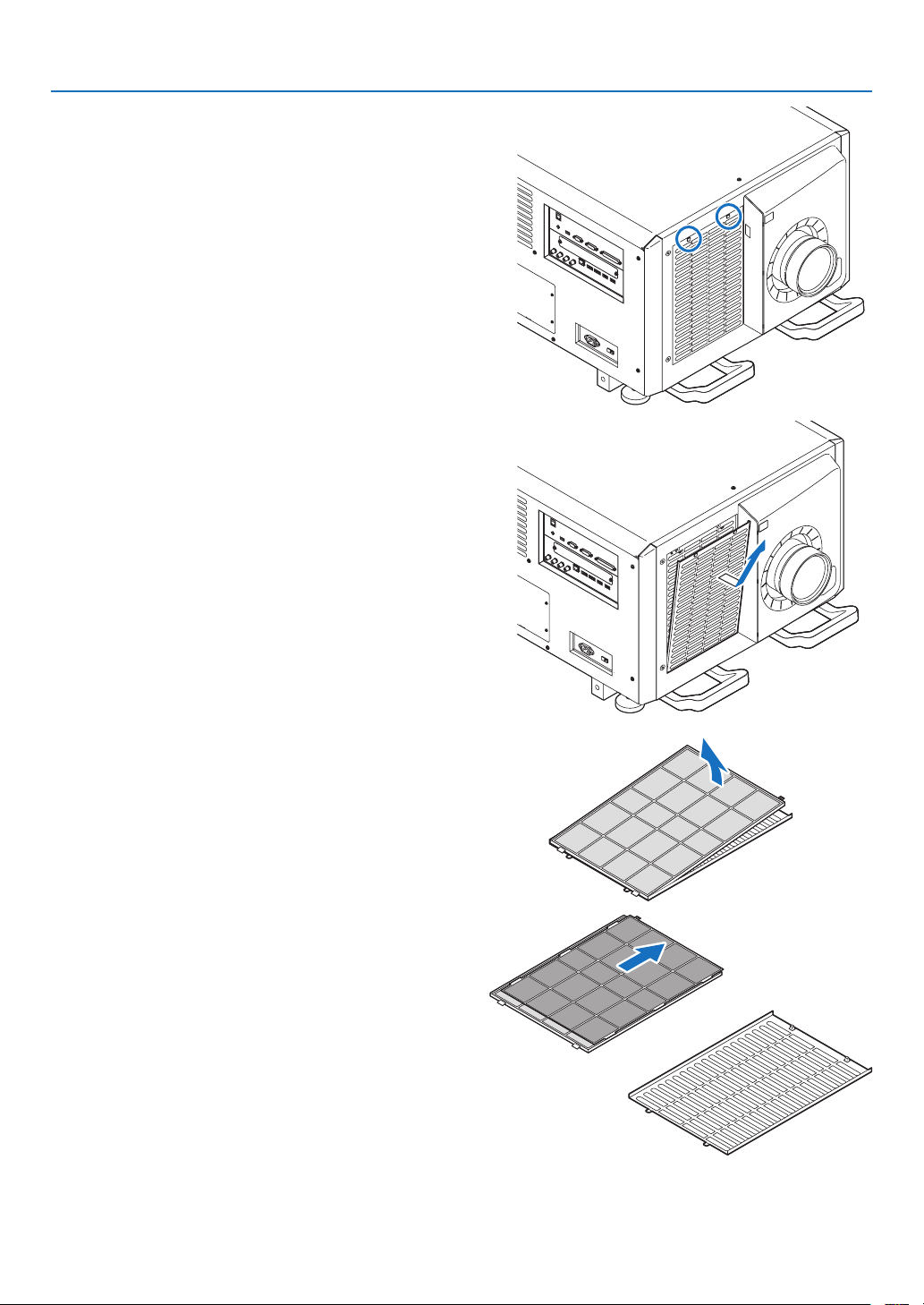
95
6. Maintenance
2. Remove the air filter.
(1) Press the stopper button (2 places).
(2) Pull the top part of the air filter towards you. Once you
have freed the upper half of the air
filter,removethe
filter by pulling it diagonally upwards.
3. Lift the air filter in the direction of the arrow and re-
move it.
4. Remove the air filters.
(1) Slide the upper air filter to the position shown below.
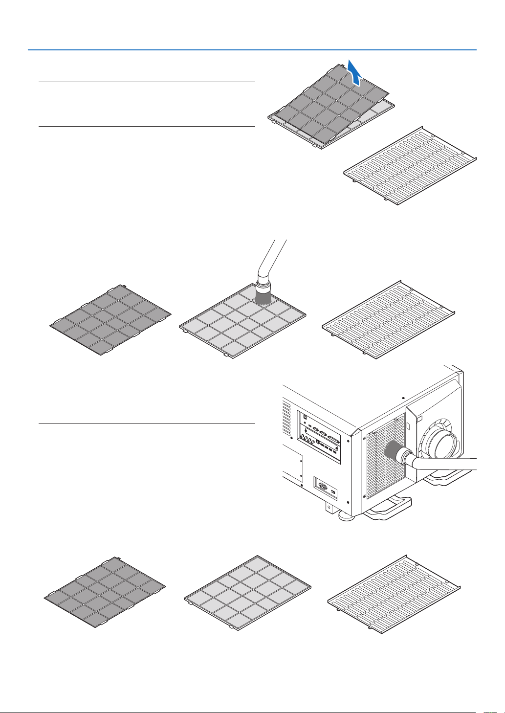
96
6. Maintenance
(2) Lift the upper air filter in the direction of the arrow and
remove it.
NOTE
•
Donotapplyahighdegreeofforceorattempttopryitopen.
Thiscoulddeformtheangemakingitimpossibletoreattach
theltercover.
5. Clean all the dust from the filters using a vacuum cleaner.
(1) Carefully remove the dust from the filter covers as well as from both sides of all the filters.
(2) Remove the dust from the grates on the outside of the
projector as well.
Be sure to also remove any dust stuck to the louver
(blind with angled horizontal slats) with a vacuum
cleaner.
NOTE
•
Wheneveryouvacuumthelter,usethesoftbrushattachment
tovacuum.Thisistoavoiddamagetothelter.
•Donotwashthelterwithwater.Doingsocanresultindam-
agetotheltermembraneandalsocauseclogging.
6. Put the various parts of the filter together and fit them inside the filter cover.
Fine grade lter Filter coverCoarse grade lter
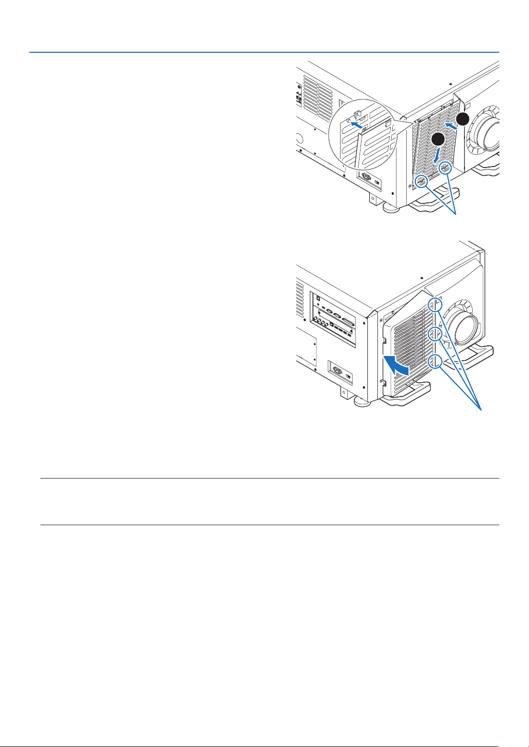
97
6. Maintenance
7. Fix the filter inside the projector unit.
(1) Snap the filter cover tabs into the cutout portion of the
projector unit to secure it.
(2) Seat the air filter aligned with the air inlet.
1
2
Cut out portion
8. Attach the front filter cover.
Push the front filter cover in the direction of the arrow to
install.
Cut out portion
9. Clean the other intake vent air filters in the same way.
Clean the other intake vent air filters in the same way as in steps (2) to (7).
NOTE
•
Beforeturningonthepower,makesurethatallltercoversareinplace.Iftheyarenotttedproperlydustcouldgetinside
theprojectorcausingittomalfunction.
•
Resetairlterusagetimeaftercleaningthelters.
6-3-2. Resetting the Air Filter Usage Time
1. Turn on the power to the projector.
2. Select [SETUP] → [RESET] and perform [CLEAR FILTER HOURS].
This completes resetting the air lter usage time.
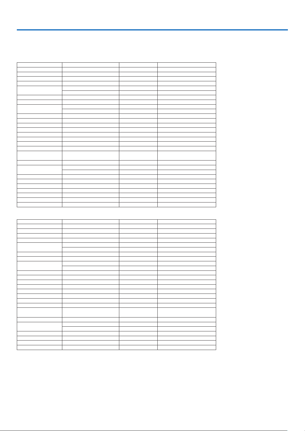
98
7. Appendix
7-1. Compatible Input Signal List
HDMI/HDBaseT
Signal Resolution ( dots ) Aspect Ratio Refresh Rate ( Hz )
VGA 640 × 480 4 : 3 60/72/75/85/iMac
SVGA 800 × 600 4 : 3 56/60/72/75/85/iMac
XGA 1024 × 768 4 : 3 60/70/75/85/iMac
HD 1280 × 720 16 : 960
WXGA
1280 × 768 15 : 960
1280 × 800 16 : 10 60
Quad-VGA 1280 × 9604 : 3 60
SXGA 1280 × 1024 5 : 4 60
FWXGA
1360 × 768 16 : 960
1366 × 768 16 : 960
SXGA+ 1400 × 1050 4 : 3 60
WXGA+ 1440 × 90016 : 10 60
WXGA++ 1600 × 90016 : 960
WSXGA+ 1680 × 1050 16 : 10 60
UXGA 1600 × 1200 4 : 3 60
Full HD 1920× 1080 16 : 960
WUXGA 1920× 1200
*
1
16 : 10 60 (Reduced Blanking)
2K 2048 × 1080 *
1
17 : 960
WQHD
iMac 27"
2560 × 1440 *
1
16 : 960
WQXGA 2560 × 1600 *
1
16 : 10 60 (Reduced Blanking)
4K
3840 × 2160 16 : 924/25/30/50*
1
/60*
1
4096× 2160 *
2
17 : 924/25/30/50*
1
/60*
1
HDTV (1080p) 1920× 1080 16 : 924/25/30/50/60
HDTV (1080i) 1920× 1080 16 : 948/50/60
HDTV (720p) 1280 × 720 16 : 950/60
SDTV (480p) 720/1440 × 480
4:3/16:960
SDTV (576p) 720/1440 × 576 4:3/16:950
SDTV (480i) 1440 × 480 4:3/16:960
SDTV (576i) 1440 × 576 4:3/16:950
DisplayPort
Signal Resolution ( dots ) Aspect Ratio Refresh Rate ( Hz )
VGA 640 × 480 4 : 3 60
SVGA 800 × 600 4 : 3 60
XGA 1024 × 768 4 : 3 60
HD 1280 × 720 16 : 960
WXGA
1280 × 768 15 : 960
1280 × 800 16 : 10 60
Quad-VGA 1280 × 9604 : 3 60
SXGA 1280 × 1024 5 : 4 60
FWXGA
1360 × 768 16 : 960
1366 × 768 16 : 960
SXGA+ 1400 × 1050 4 : 3 60
WXGA+ 1440 × 90016 : 10 60
WXGA++ 1600 × 90016 : 960
WSXGA+ 1680 × 1050 16 : 10 60
UXGA 1600 × 1200 4 : 3 60
Full HD 1920× 1080 16 : 960
WUXGA 1920× 1200
16 : 10 60 (Reduced Blanking)
2K 2048 × 1080 17 : 960
WQHD
iMac 27"
2560 × 1440 16 : 960
WQXGA 2560 × 1600 16 : 10 60 (Reduced Blanking)
4K
3840 × 2160 16 : 924/25/30/50/60
4096× 2160 *
2
17 : 924/25/30/50/60
HDTV (1080p) 1920× 1080 16 : 924/25/30/50/60
HDTV (720p) 1280 × 720 16 : 950/60
SDTV (480i/p) 720/1440 × 480
4:3/16:960
SDTV (576i/p) 720/1440 × 576 4:3/16:950
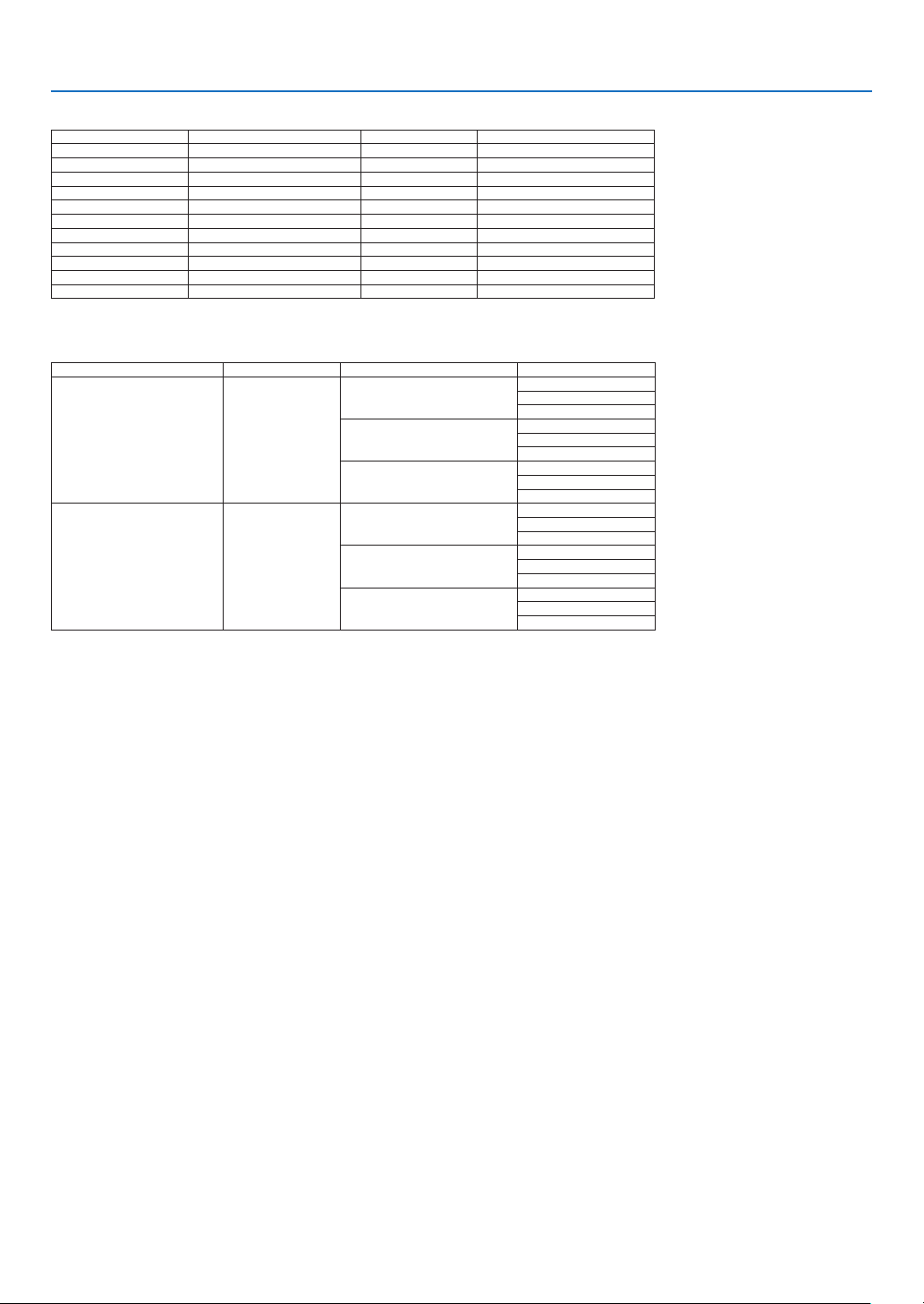
99
7. Appendix
SDI
Signal Resolution ( dots ) Aspect Ratio Refresh Rate ( Hz )
HD-SDI (1035i) 1920× 1035 16 : 960
HD-SDI (1080i) 1920× 1080 16 : 950/60
HD-SDI (1080p) 1920× 1080 16 : 924pSF
HD-SDI (1080p) 1920× 1080 16 : 924/25/30
HD-SDI (720p) 1280 × 720 16 : 924/25/30/50/60
3G-SDI (1080p) 1920× 1080 16 : 950/60
3G-SDI (1080p) 1920× 1080 16 : 924/25/30
3G-SDI (1080p) 1920× 1080 16 : 924pSF
3G-SDI (1080i) 1920× 1080 16 : 950/60
Quad SDI 3840 × 2160 16 : 924/25/30/50/60
Quad SDI 4096× 2160 *
2
17 : 924/25/30/50/60
HDBaseT / DisplayPort 3D
Signal Resolution ( dots ) Aspect Ratio Refresh Rate ( Hz ) 3D Format
1920× 1080p 16 : 9
23.98/24
Frame Packing
Side By Side (Half)
Top and Bottom
25
Frame Packing
Side By Side (Half)
Top and Bottom
29.97/30
Frame Packing
Side By Side (Half)
Top and Bottom
1280 × 720p 16 : 9
23.98/24
Frame Packing
Side By Side (Half)
Top and Bottom
25
Frame Packing
Side By Side (Half)
Top and Bottom
29.97/30
Frame Packing
Side By Side (Half)
Top and Bottom
*1 HDBaseT does not support this signal.
*2 Native resolution
•Uponshipment,theprojectorissetforsignalswithstandarddisplayresolutionsandfrequencies,butadjustmentsmayberequired
depending on the type of computer.

100
7. Appendix
7-2. Indicator Messages
This section helps you resolve problems you may encounter while setting up or using the projector.
POWER Indicator
Indicator display Projector status Procedure
OffPower is off. –
Flashing Green (short ashes) Preparing to power up or cooling the main
unit
When the projector is in the standby state,
the rmware is ready to be updated
Wait a while.
Green (twice per cycle) Firmware is ready to be updated –
Green (long ashes)
Offtimer(enabled)
Program timer (off time enabled)
–
Orange(longashes)Program timer (on time enabled) –
Lit Green Power on –
OrangeStandby mode –
STATUS Indicator
Indicator display Projector status Procedure
OffNo problem –
Flashing Green (short
ashes)
Shutter is closed –
Green (long
ashes)
Power on (The light mod-
ule is turned off.)
–
OrangeButton has been pressed
while projector is in key
lock mode
The projector’s keys are locked. The setting must be can-
celed to operate the projector.
Projector’s ID number
and remote control’s ID
number do not match
Check the control IDs.
Projector cooling Wait a while.
Red Error occurring Contact your distributor or service personnel. Let us know
the details displayed on the liquid crystal indicator panel
then.
Lit Green Power on –
OrangeStandby mode –
Red Error requiring service
support
Ask your distributor or service personnel for repair. Let us
know the details displayed on the liquid crystal indicator
panel then.
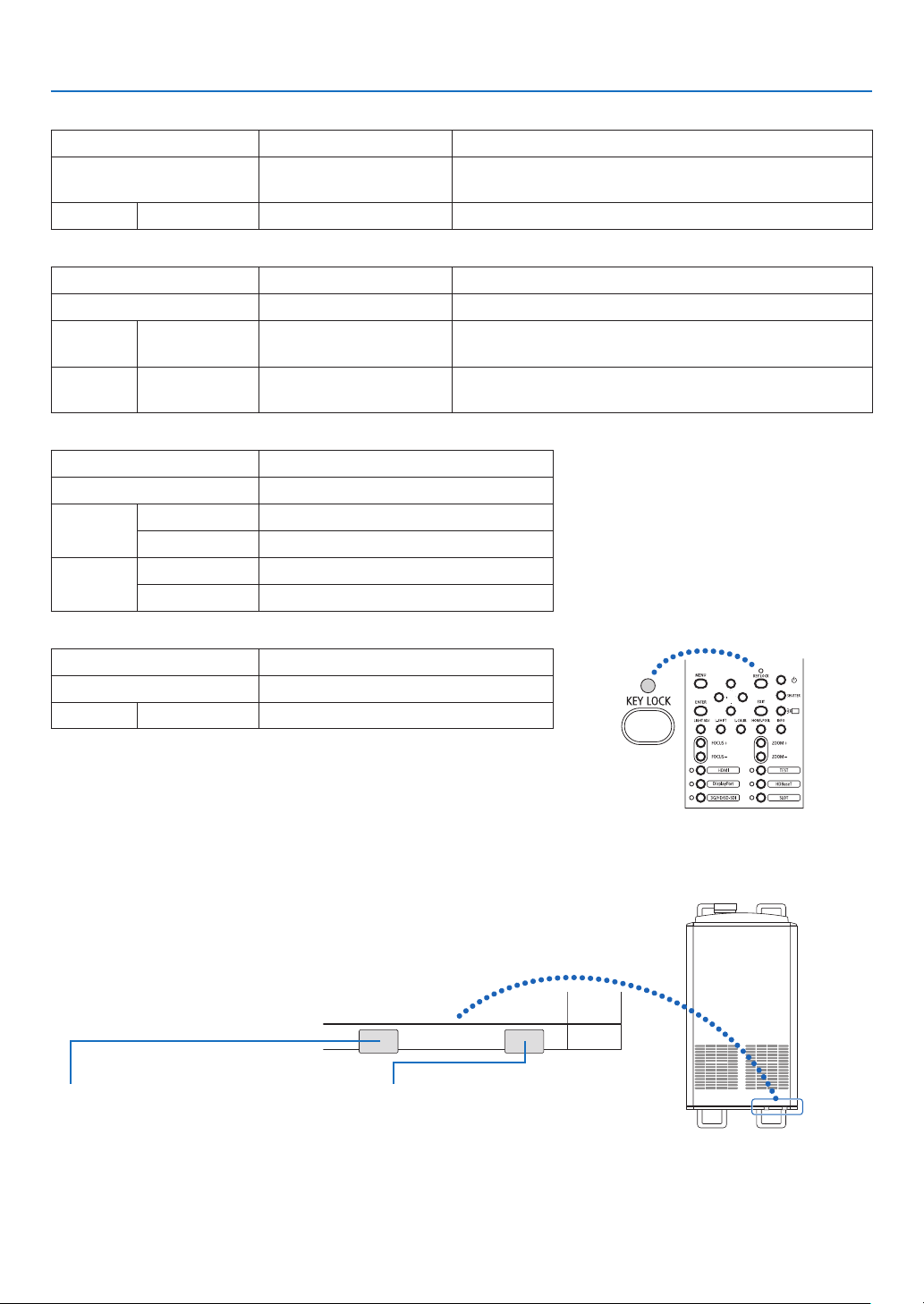
101
7. Appendix
LIGHT Indicator
Indicator display Projector status Procedure
OffThe light module is turned
off.
–
Lit Green Light module lit –
TEMP. Indicator
Indicator display Projector status Procedure
OffNo problem
Flashing Red Temperature problem Ambient temperature is out of the operation temperature.
Check if any obstruction stays near the exhaust vent.
Lit Red High surrounding tem-
perature
The surrounding temperature is high. Lower the room
temperature.
SHUTTER Indicator
Indicator display Projector status
OffShutter is open.
Flashing Green Performing the lens calibration.
OrangeLens calibration implement request.
Lit Green Shutter is closed.
Orange
Onscreenmuting
KEY LOCK Indicator
Indicator display Projector status
Off
[CONTROLPANELLOCK][OFF]
Lit Orange[CONTROLPANELLOCK][ON]
REAR LED
When[REARLED]under[NOTIFICATIONSETTINGS]issetto[ON],theoperationisasshownbelow.Whensetto
[OFF],therearLEDisalwaysoff.
Light status indicator
Off:Thelightmoduleisturnedoff
On(white):Lightmodulelit
System status indicator
OperatesinthesamewayastheSTATUS
indicator.

102
7. Appendix
If the temperature protector is activated
If the projector’s internal temperature rises abnormally, the light module turns off and the temperature indicator ashes.
It may happen that the projector’s temperature protector is simultaneously activated and the projector’s power turns off.
If this happens, do the following:
- Unplug the power cable from the power outlet.
- If using in a place where the surrounding temperature is high, move the projector to a different, cool place.
- If there is dust in the ventilation holes, clean. (→ page
93, 94)
- Wait as such about 1 hour for the projector’s internal temperature to lower.
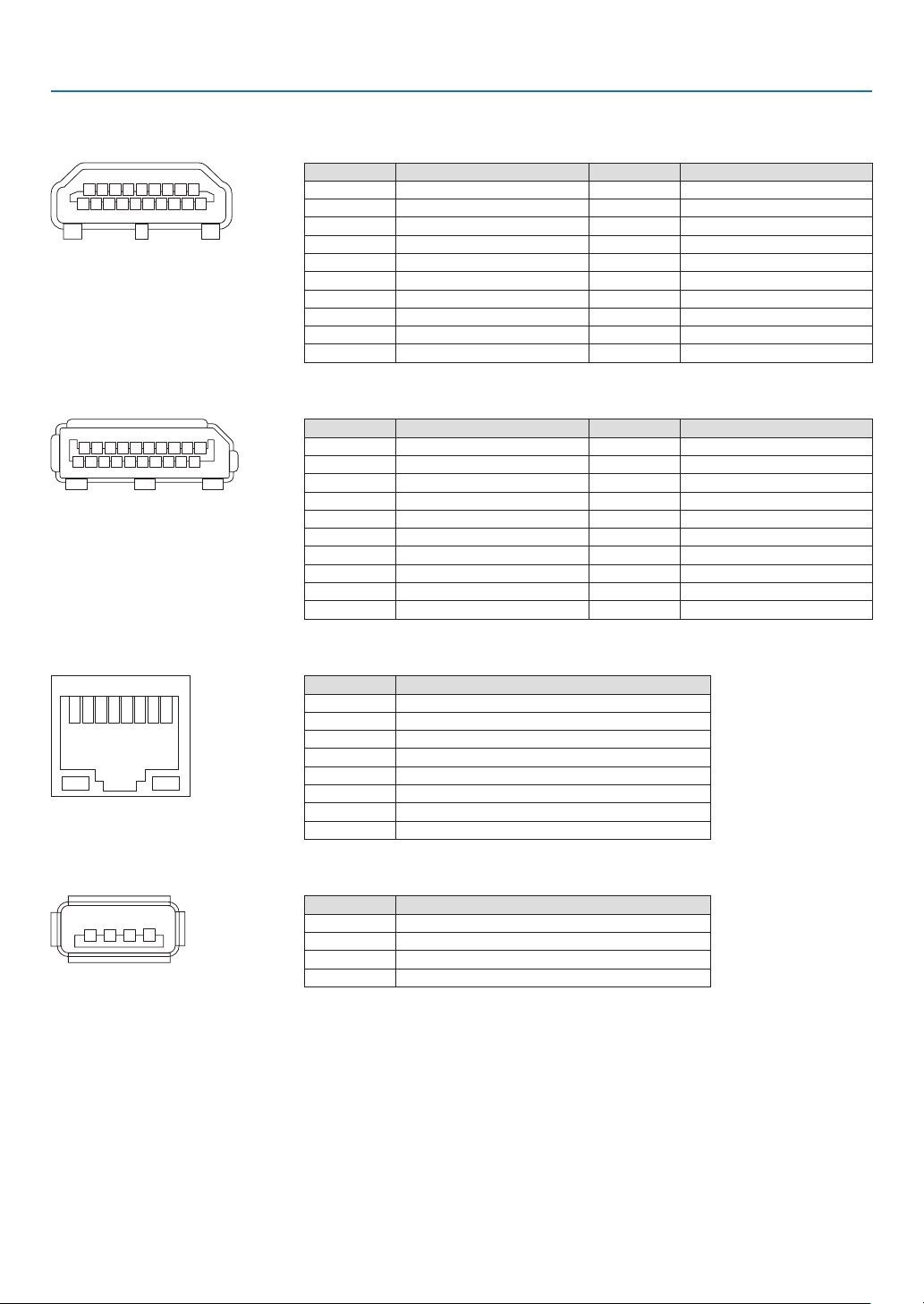
103
7. Appendix
7-3. Pin assignments and signal names of main terminals
HDMI1/2 IN Terminal (Type A)
135791113151719
246810 12 14 16 18
Pin No. Signal Pin No. Signal
1 TMDS Data 2+ 11 TMDS Clock Shield
2 TMDS Data 2 Shield 12
TMDSClock−
3 TMDSData2−13 CEC
4 TMDS Data 1+ 14 Disconnection
5 TMDS Data 1 Shield 15 SCL
6
TMDSData1−16 SDA
7 TMDS Data 0+ 17 DDC/CEC grounding
8 TMDS Data 0 Shield 18 +5 V power supply
9
TMDSData0−19Hot plug detection
10 TMDS Clock +
DisplayPort1/2 IN Terminal
135791113151719
246810 12 14 16 18 20
Pin No. Signal Pin No. Signal
1
Mainlinklane3−11 Grounding 0
2 Grounding 3 12 Main link lane 0+
3 Main link lane 3+ 13 Conguration 1
4
Mainlinklane2−14 Conguration 2
5 Grounding 2 15 Supplementary channel +
6 Main link lane 2+ 16 Grounding 4
7
Mainlinklane1−17 Supplementarychannel−
8 Grounding 1 18 Hot plug detection
9Main link lane 1+ 19Return
10
Mainlinklane0−20 +3.3 V power supply
HDBaseT Port (RJ-45)
12345678
Pin No. Signal
1 TxD+/HDBT0+
2 TxD−/HDBT0−
3 RxD+/HDBT1+
4 Disconnection/HDBT2+
5 Disconnection/HDBT2−
6 RxD−/HDBT1−
7 Disconnection/HDBT3+
8 Disconnection/HDBT3−
USB Port (Type A)
1
3 24
Pin No. Signal
1 V
BUS
2 D−
3 D+
4 Grounding
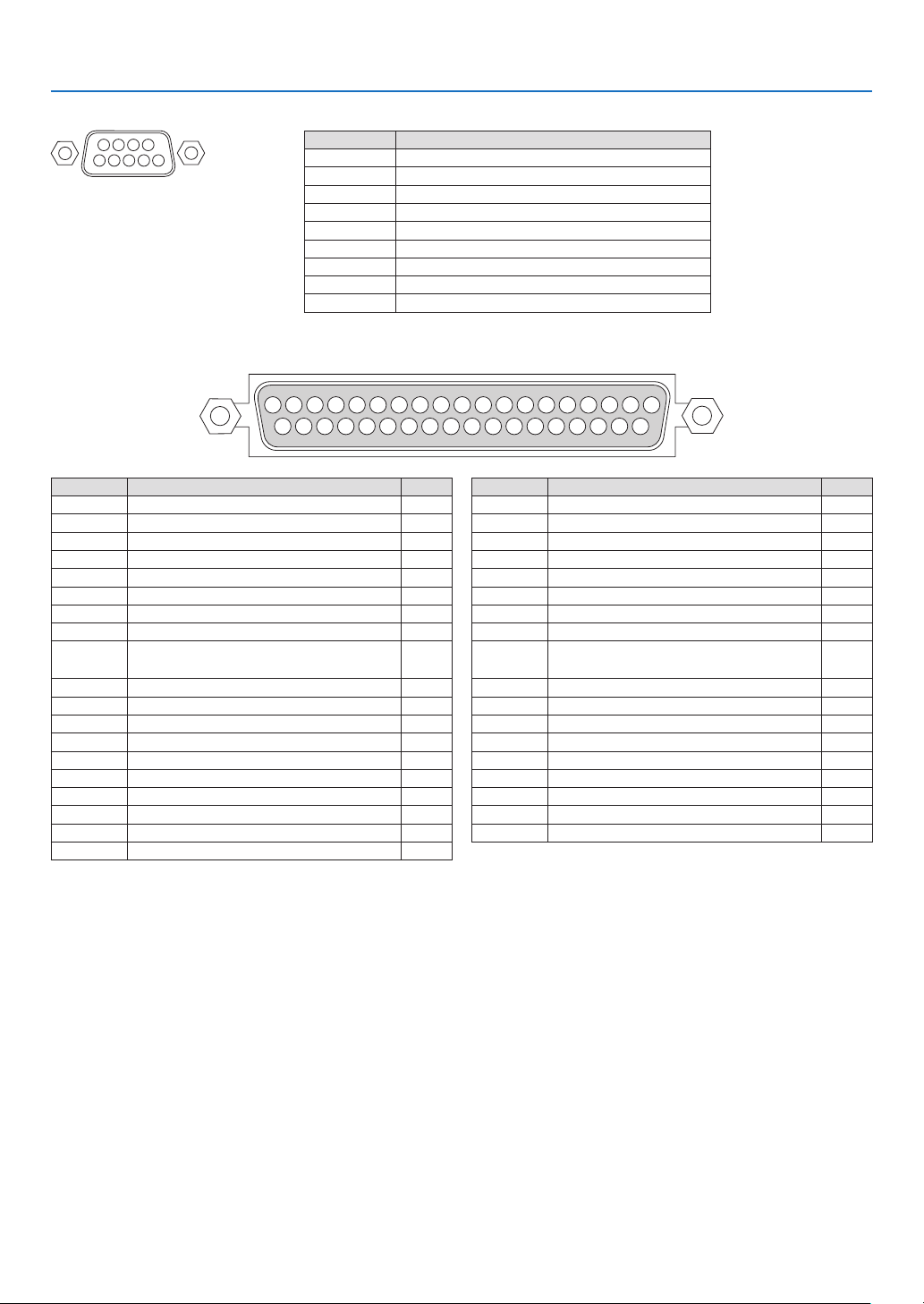
104
7. Appendix
RS-232C terminal (PC control) (D-Sub 9 Pin)
1234
5
6789
Pin No. Signal
1 Unused
2 Transmission data
3 Reception data
4 Connection/Pin 6
5 Grounding
6 Connection/Pin 4
7 Unused
8 Unused
9Unused
GP I/O terminal (External control) (D-sub 37 pin)
19 18 17 16 15 14 13 12 11 10 987654321
37 26 35 34 33 32 31 30 29 28 27 26 25 24 23 22 21 20
Pin No. Signal Name I/O
1 reserved IN
2 reserved IN
3 reserved
4 reserved
5 EXT_GPIN1+ (Control) IN
6 EXT_GPIN2+ (Control) IN
7 EXT_GPIN3+ (Control) IN
8 EXT_GPIN4+ (Control) IN
9
GPOUT1+(External3DL/ROutput
Reference +)
OUT
10 reserved OUT
11 reserved OUT
12 reserved OUT
13 reserved OUT
14 reserved OUT
15 reserved OUT
16 reserved OUT
17 NC (not connected) —
18 GND PWR
19GND PWR
Pin No. Signal Name I/O
20 reserved IN
21 reserved IN
22 reserved IN
23 reserved IN
24 EXT_GPIN1- (Control) IN
25 EXT_GPIN2- (Control) IN
26 EXT_GPIN3- (Control) IN
27 EXT_GPIN4- (Control) IN
28
GPOUT1-(External3DL/ROutput
Reference -)
OUT
29reserved OUT
30 reserved OUT
31 reserved OUT
32 reserved OUT
33 reserved OUT
34 reserved OUT
35 reserved OUT
36 NC (not connected) —
37 GND PWR
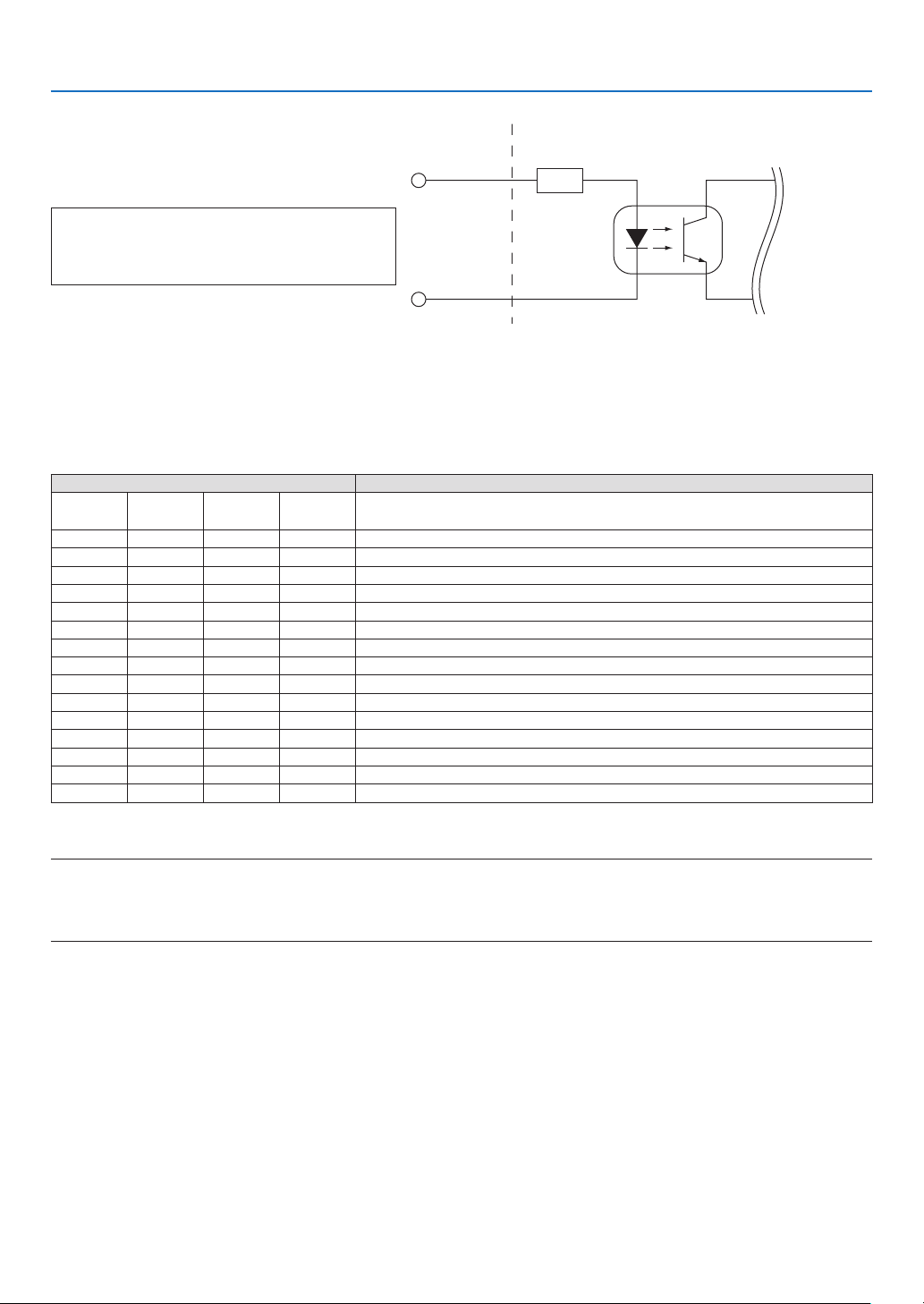
105
7. Appendix
Inside Projector
Voltage applied across the pins of Ext_GPIN_P and Ext_GPIN_N
should be in the range from 3.3 Vdc to 10 Vdc.
Recommended Operating Current: 5 mA
Absolute Maximum Rating: 23 mA
Resist = 360 Ω
Photo-coupler
Forward direction voltage: 1.1 V (@5 mA)
GP I/O Connector
Pin No.: 5 6 7 8
Pin No.: 24 25 26 27
Ext_GPIN_P
Ext_GPIN_N
Using GPIO Control
Momentary“ON”pulseenablesyoutocontrolprojector.Toenable“ON”pulse,holditforatleast300ms.Hold“OFF”
foratleast300msbefore“ON”.
HereisfunctionlisttocontrolprojectorbyusingGPIOport.
Photo-coupler ON/OFF Function
8-27 7-26 6-25 5-24 The following functions apply depending on the combination of input
terminals.
OFFOFFOFFON
PowerON
OFFOFFONOFFPowerOFF
OFFOFFONONShutterCLOSE
OFFONOFFOFFShutterOPEN
OFFONOFFONSelect HDMI1
OFFONONOFFSelect DisplayPort1
OFFONONONSelect SDI1
ONOFFOFFOFFSelect SDI2
ONOFFOFFONSelect SDI3
ONOFFONOFFSelect SDI4
ONOFFONONSelect HDBaseT
ONONOFFOFF
SelectSLOT
ONONOFFONSelect HDMI2
ONONONOFFSelect DisplayPort2
ONONONONreserved
ExampleforsettingtheshuttertoCLOSE:InputONto6-25and5-24while8-27and7-26areOFF.
NOTE:
•TheoperationcommandcomingfromGPI/Oportwillbecanceledwhentheprojectorisprocessingothertasks.
•Setallotherpinsthanthoseinuseto“OFF”.
•Theoperationcommandisexecuteduponcontinuousinputofthe“ON”pulseforapproximately300ms.
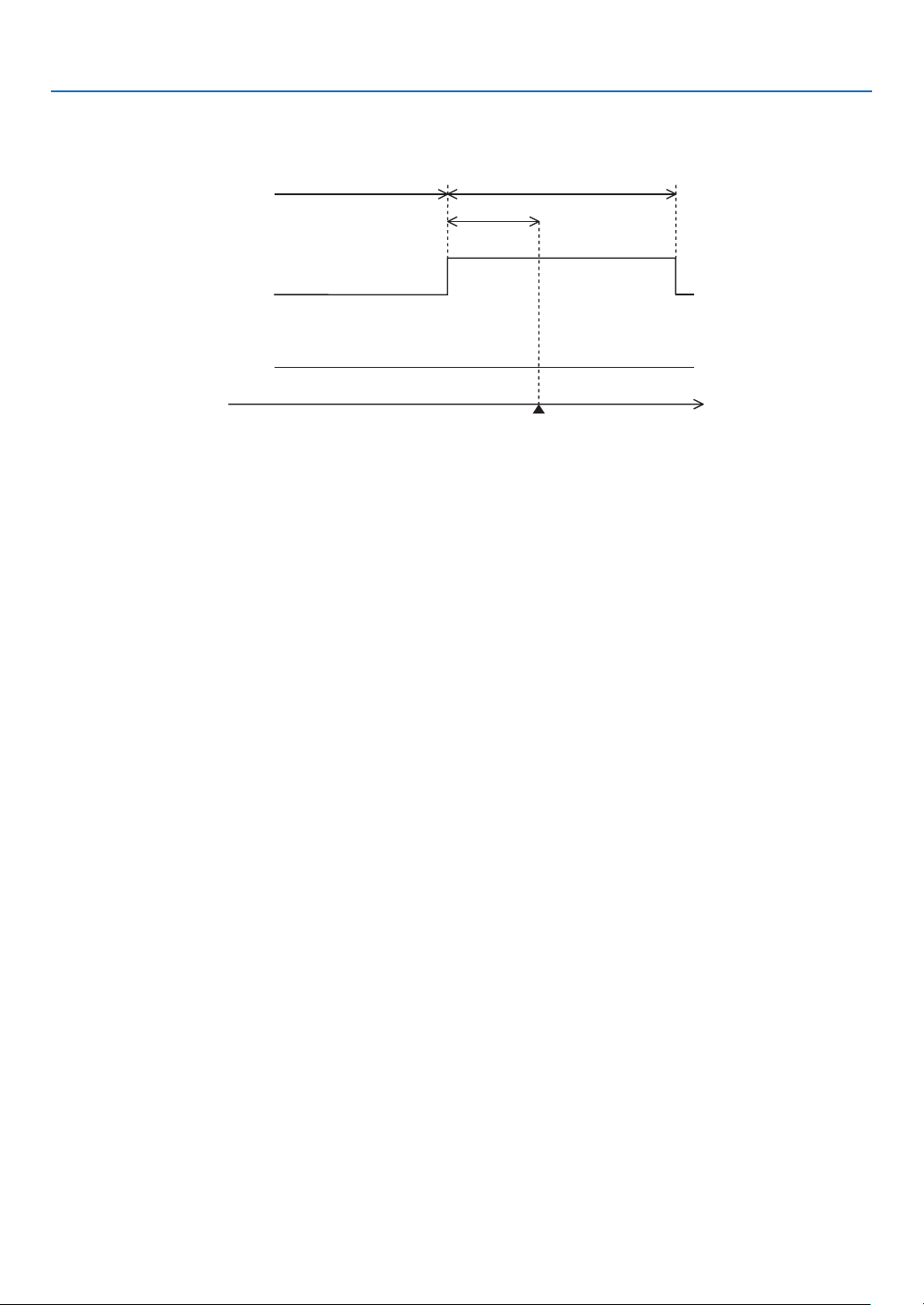
106
7. Appendix
Timing chart of GPIO control
Example of Select HDMI1
Off at least 300 ms at least 300 ms
approx. 300 ms
Execute
Select HDMI1
time
5-24/7-26
6-25/8-27
on
off
on
off
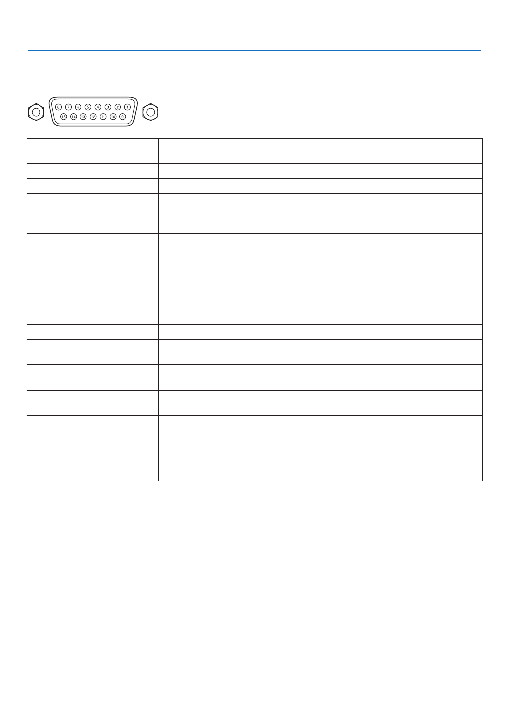
107
7. Appendix
3D terminal (D-sub 15 pin)
This is used to connect a 3D image system to the projector.
Pin view of a female connector
Pin
No.
Signal Name I/OFunction
1 +12V PWR Supplies power (+12V) to the 3D image system
2 GNDC GND Ground
3 GNDC GND Ground
4 RS232_RX IN
Data transmission from the 3D image system (1200 Baud, 8 bits, No
Parity)
5 RS232_TX OUTData transmission to the 3D image system (1200 Baud, 8 bits, No Parity)
6 CONN_3D_MODE+OUT
3D mode status (+) (Connects to the collector of the output transistor of
the photo coupler inside the projector)
7 CONN_SYNC+OUT
3D L/R switching timing signal (+) (Connects to the collector of the output
transistor of the photo coupler inside the projector)
8
3D_INPUT_REFER-
ENCE+
IN
3D L/R timing signal (+) (Connects to the anode of the input diode of the
photo coupler inside the projector)
9+12V PWR Supplies power (+12V) to the 3D image system
10
3D_INPUT_REFER-
ENCE−
IN
3DL/Rtimingsignal(–) (Connects to the cathode of the input diode of
the photo coupler inside the projector)
11
3D_DISPLAY_REFER-
ENCE+
IN
3D L/R display timing signal (+) (Connects to the anode of the input diode
of the photo coupler inside the projector)
12
3D_DISPLAY_REFER-
ENCE−
IN
3DL/Rdisplaytimingsignal(–) (Connects to the cathode of the input
diode of the photo coupler inside the projector)
13 CONN_3D_MODE−OUT
3Dmodestatus(–) (Connects to the emitter of the output transistor of
the photo coupler inside the projector)
14 CONN_SYNC−OUT
3DL/Rswitchingtimingsignal(–) (Connects to the emitter of the output
transistor of the photo coupler inside the projector)
15 N/C −Unused
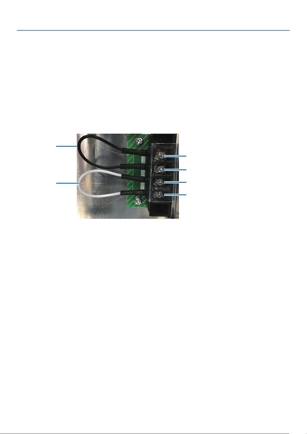
108
7. Appendix
7-4. Remote Interlock Connector
This connector functions as safety device for the projector. The contacts are normally closed. When an abnormality
occurs, the contacts open to immediately stop the projector (interlock state) (shipped with a shorting wire installed).
By replacing the shorting wire with wiring and attaching it to the contacts, the projector can be immediately stopped
remotely when an abnormality occurs in the projector.
Follow the following procedure to recover from the interlock state.
1.
Disconnect the AC power supply to the projector body.
2. Remove the plate inlet or side panel (page
17, 31).
3.
Connect the contacts to the remote interlock connector and attach the plate inlet or side panel.
4. Connect the AC power supply to the projector body.
Remote interlock connector (exterior view)
#1
#2
#3
#4
Shorting wire 2
Shorting wire 1
•Theremoteinterlockterminalisequippedoninsideofthesidecover.
Remove the plate inlet or side panel for connection.
•Securelyreinstalltheplateinletorsidepanel.
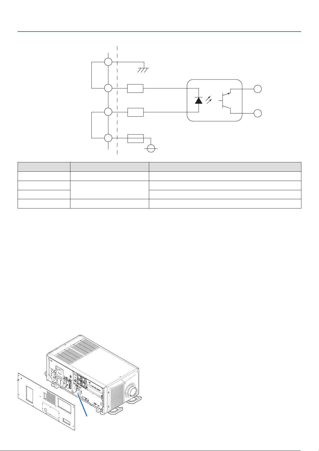
109
7. Appendix
Circuit diagram
Shorting wire 1
Shorting wire 2
Interlock connector Inside projector
390Ω/0.5Wresistor
390Ω/0.5Wresistor
GND
4
3
2
1
1A fuse
VCC +5V
Photocoupler
Connector no. PhotocouplerON/OFFDescription
1 — +5V supply
2 ON/OFFConnects to the photocoupler anode inside the projector
3 Connects to the photocoupler cathode inside the projector
4 — Ground
When the length of the wiring is less than 5 m (approximate)
Remove shorting wire 1 or shorting wire 2 and connect the external contacts (switch) to the projector interlock terminal
(1 and 2 or 3 and 4) by cable.
• The projector operates normally when the contacts are closed and the system shuts off when the contacts are open.
• A power supply external from the projector is not necessary.
• A maximum of 2 sets of external contacts can be connected. If you are only using a single set of external contacts,
connecting the shorting wire to the interlock terminal you are not using.
• The minimum rating required of the external contacts is 2mA.
When the length of the wiring is at least 5 m (approximate)
Remove shorting wire 1 and shorting wire 2 and connect the external device to the projector interlock terminals (2
and 3) (do not use 1 and 4).
• Connect terminal 2 to the positive side of the external device and connect terminal 3 to the negative side.
• The projector operates normally when a voltage in the range of DC5 to 16V is applied between terminals 2 and 3,
and the system shuts off when the voltage is 0V.
• The minimum rated current required of the external device varies depending on the voltage applied between the
terminals by the external device.
• When feeding the cable out from the projector, feed it so that it passes through the hole on the side face of the
projector.
Pull the cable through here.
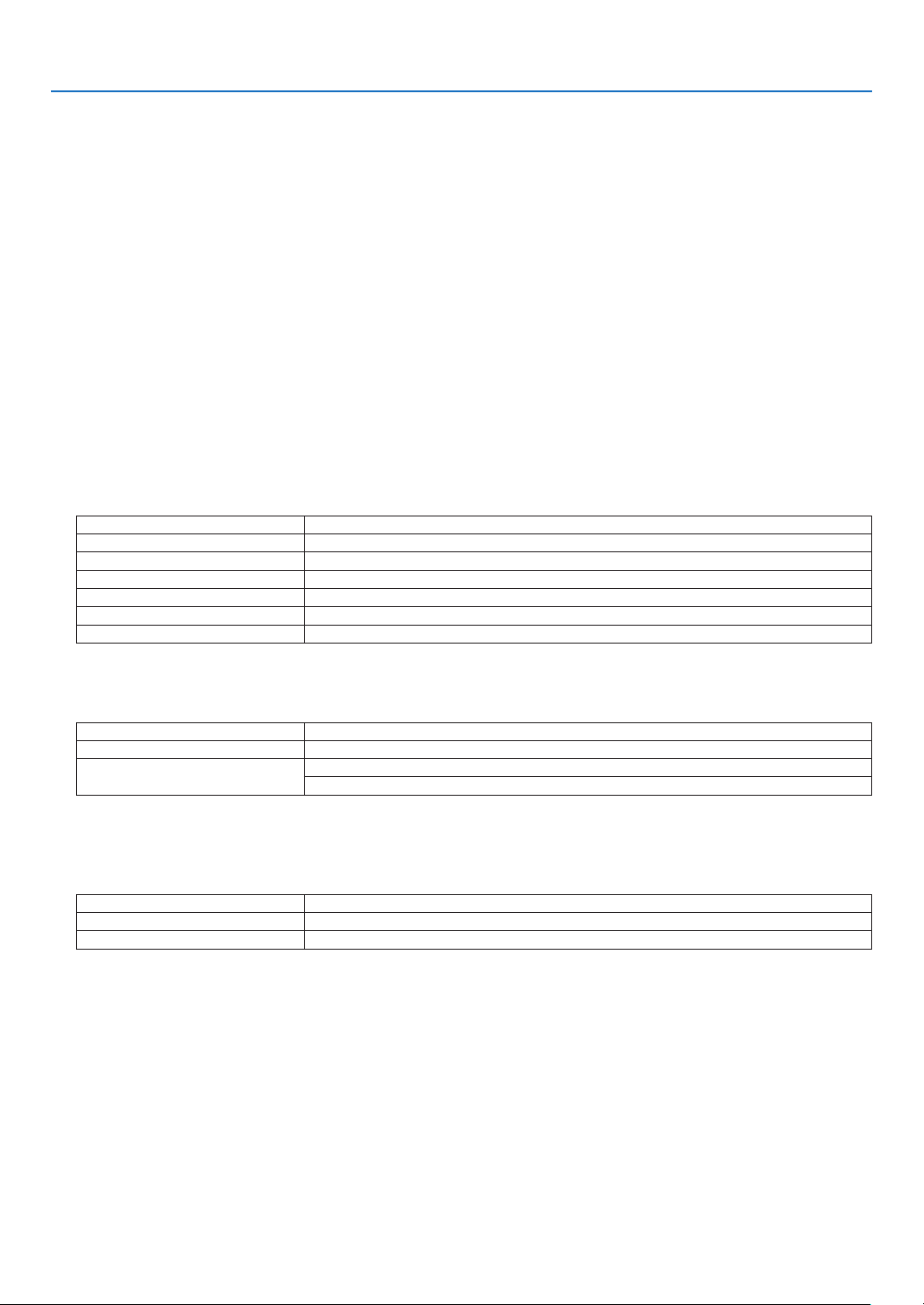
110
7. Appendix
7-5. About the ASCII Control Command
This device supports the common ASCII Control Command for controlling our projector and monitor.
Please visit our web site for detailed information about the command.
https://www.nec-display.com/dl/en/pj_manual/lineup.html
HOW TO CONNECT WITH AN EXTERNAL DEVICE
There are two methods to connect the projector with an external device such as a computer.
1. Connection thru the serial port.
Connects the projector to a computer by a serial cable (straight cable).
2. Connection via network (LAN/HDBaseT)
Connects the projector to a computer by a LAN cable.
Concerning to the type of LAN cable, please ask to your network administrator.
CONNECTION INTERFACE
1. Connection thru the serial port.
Communication Protocol
Item Information
Baud rate
115200/38400/19200/9600/4800bps
Data length 8 bits
Parity bit No parity
Stop bit 1 bit
Flow control None
Communications procedure Full duplex
2. Connection via network
Communication Protocol (Connection via LAN)
Item Information
Communication speed Set automatically (10/100 Mbps)
Supported standard IEEE802.3 (10BASE-T)
IEEE802.3u (100BASE-TX, Auto-Negotiation)
Use the TCP port number 7142 for transmitting and receiving command.
Communication Protocol (Connection via HDBaseT)
Item Information
Communication speed 100 Mbps
Supported standard IEEE802.3u (100BASE-TX, Auto-Negotiation)
Use the TCP port number 7142 for transmitting and receiving command.

111
7. Appendix
PARAMETERS FOR THIS DEVICE
Input command
Input terminal Response Parameter
HDMI1 hdmi1 hdmi1 or hdmi
HDMI2 hdmi2 hdmi2
DisplayPort1 displayport1 displayport1 or displayport
DisplayPort2 displayport2 displayport2
HDBaseT hdbaset hdbaset or hdbaset1
SDI1 sdi1 sdi1 or sdi
SDI2 sdi2 sdi2
SDI3 sdi3 sdi3
SDI4 sdi4 sdi4
SLOTslot slot or slot1
Status command
Response Error Status
error:temp Temperature error
error:fan Fan trouble
error:light Light source trouble
error:lens Lens trouble
error:system System trouble
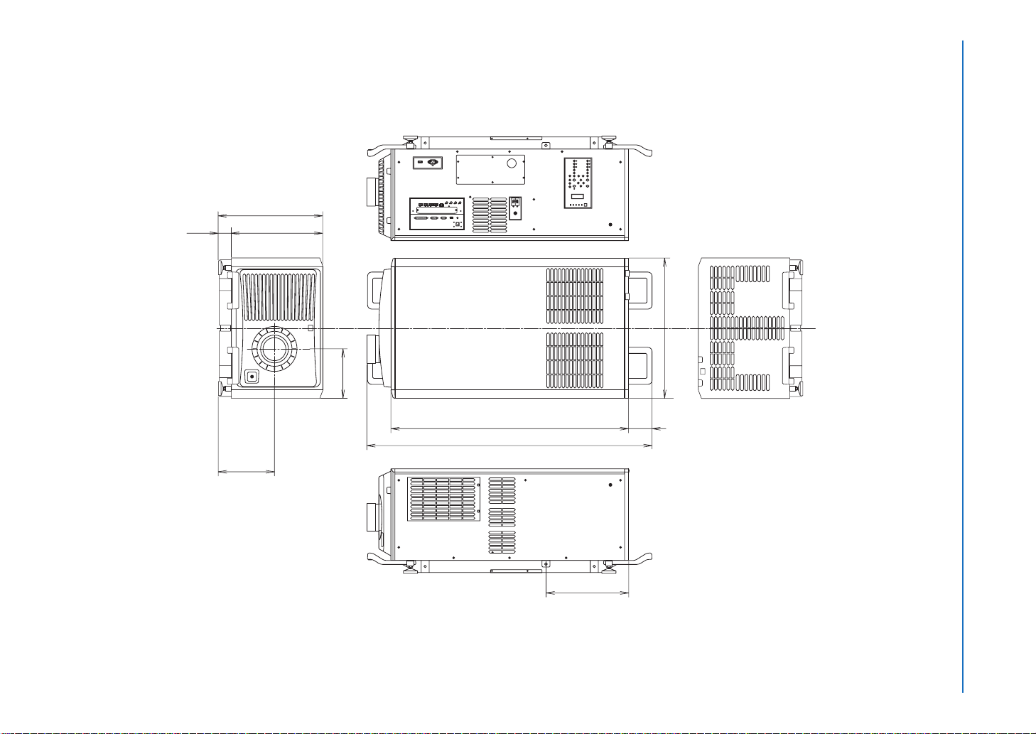
112
7. Appendix
1180 (46.5)
116
(4.6)
1412 (55.6)
697 (27.4)
244.5 (9.6)
278.5 (11)
519.1 (20.4)
454.6 (17.9)
64.5 (2.5)
410 (16.1)
7-6. Outline Drawing
Unit: mm (inch)
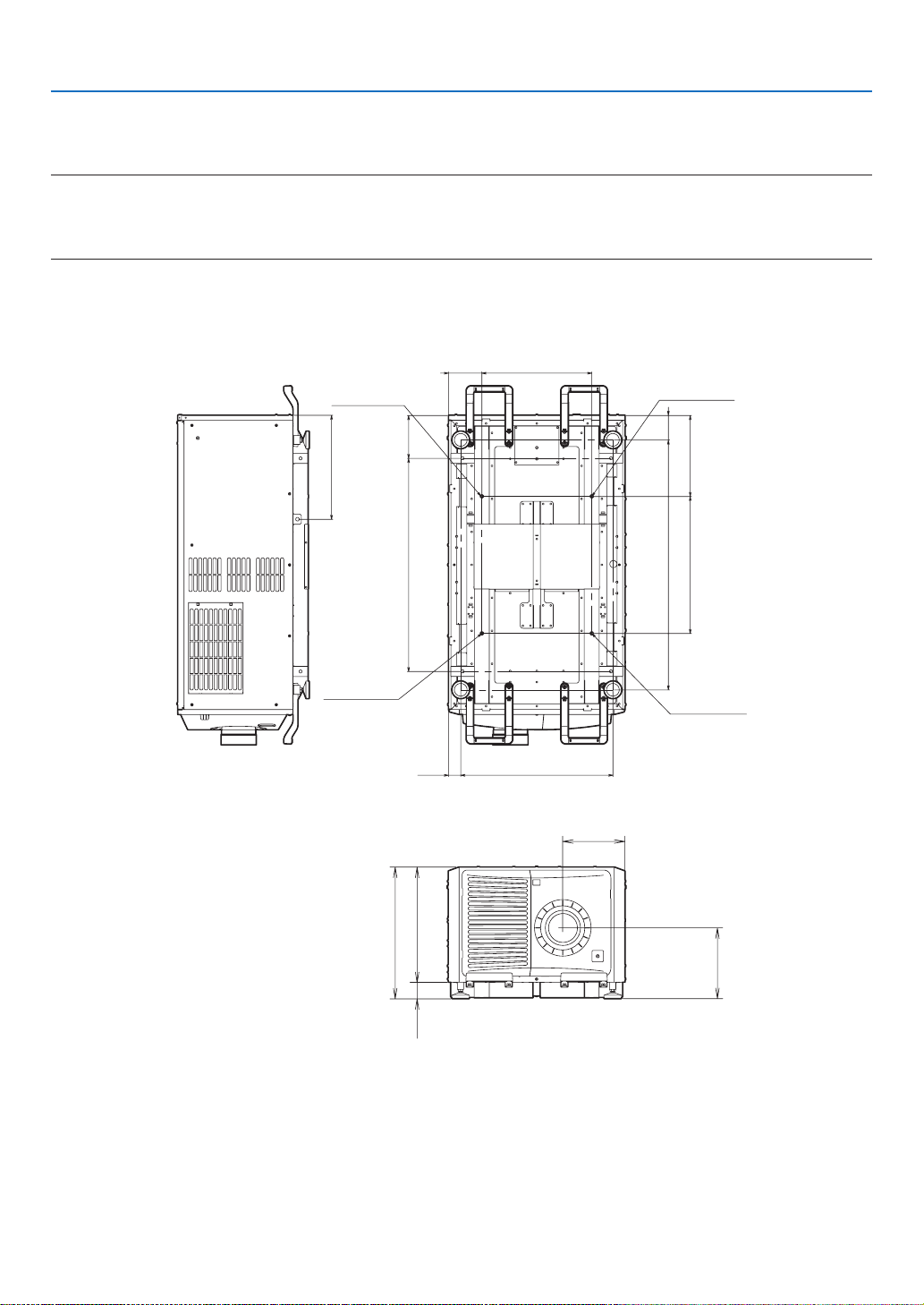
113
7. Appendix
7-7. Special Installation
This projector can be installed in various ways, including on the oor.
NOTE:
•Whenturningtheprojectorupsidedownduringinstallation,useasoftcloth,etc.,toprotecttheprojectorfromscratches.
•Whensuspendingorincliningtheprojector,checkthatalltheltercoversareproperlymounted.Ifnot,thestoppersmaycome
offduringtheinstallationprocedureandtheltercoverscouldfall.
7-7-1. Installing the Projector on the Ceiling
To install the projector on the ceiling, install it by referring to the following specications.
170840
97.5
985
48.5 600
320540
131.8
433.4
Max M8x20
Max M8x20
Max M8x20
Max M8x20
410
244.5
278.5
519.1
454.664.5
Unit: mm
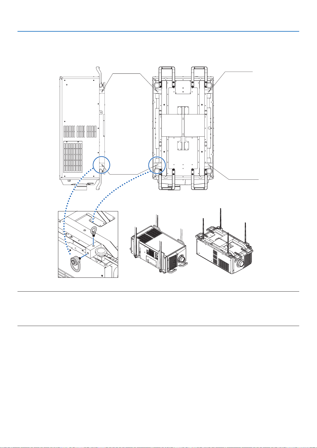
114
7. Appendix
7-7-2 Installing using eye bolts
Eye bolts can be used to lift and move the projector or to install it permanently suspended from the ceiling.
Mount the eye bolts to the bottom or side surface of the blocks shown in the diagram below.
Max M10x20
Max M10x20
Max M10x20
Max M10x20
NOTE:
•Cautionswhenusingeyebolts
Whenmountingeyeboltsonthesidesurfaceandsuspendingtheprojectorfromtheside,besuretouseswiveleyebolts.
Also,useacushioningmaterialoverthewireinpartswhereitcomesincontactwiththeprojectortoprotecttheprojectorfrom
scratches.
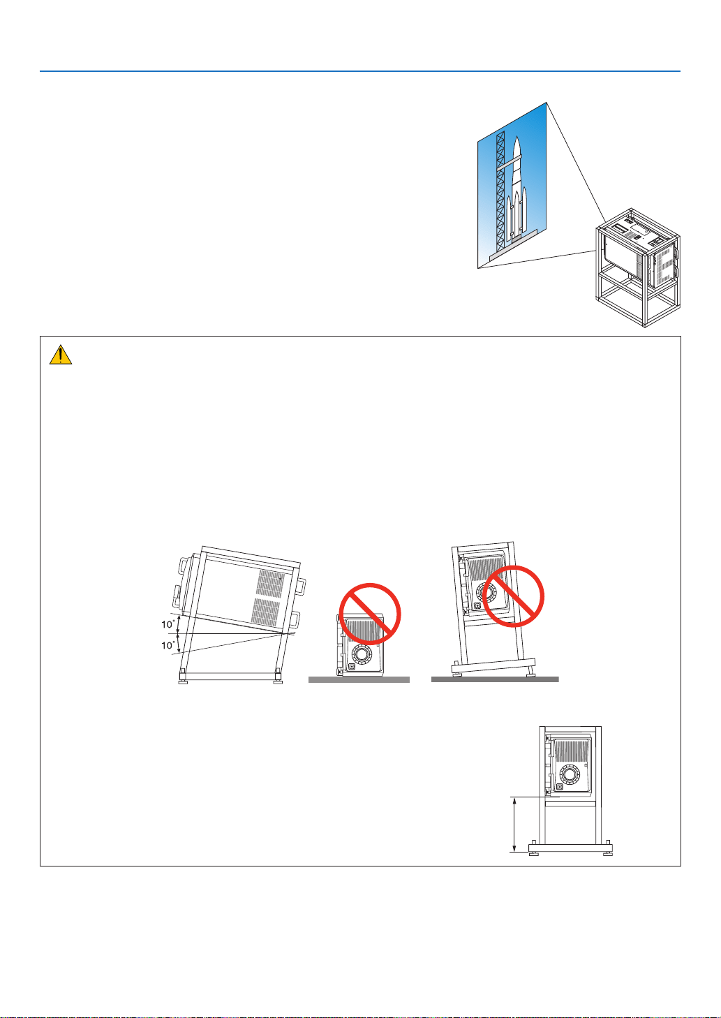
115
7. Appendix
7-7-3. Installation for free tilting or portrait projecting
This projector can be set to any angle within a vertical 360° range. how-
ever, it cannot be installed with right or left slant.
If you install the projector vertically you can project screens from your
computer and other sources in portrait orientation.
•BesuretoinstallthedevicewiththesidewheretheConnectiontermi-
nals and Controls/Indicator Panel are located facing the top.
•Angletodisplayallthescreenssuchastheon-screenmenucanbe
changed by the menu [SETUP] → [MENU (2)] → [MENU ANGLE].
Precautions for the portrait insntallation
•Donotsimplysettheprojectorverticallyontheoororonatable.Theprojectormayfallover,resultingininjury,
damage, malfunction or hazardous laser radiation exposure. Also the intake vent may become blocked causing
the unit’s internal temperature to rise resulting in malfunction and risk of re.
•Forportraitinstallationtheintakeventsmustbeinstalledatthetopandbottom.Toensureairowtothebottom
intake vent, a rack to support the unit is necessary. Please hire an installation service provider (for a fee) to
make a custom portrait projection stand.
•Wheninstalledinportraitorientationtheprojectorcanbetiltedforwardorbackward
within a range of ± 10°. Tilting the projector forward or backward outside of this range, or tilting it to the left or to
the right could cause it to malfunction.
•Toensureairow,maintain60cm/23.6"ofspacebetweentheintake
vent and the installation surface.
(NOTE)Intheguretotherightthereisplentyofspacebehind,above,
and on either side of the projector unit.
60 cm/23.6" or greater
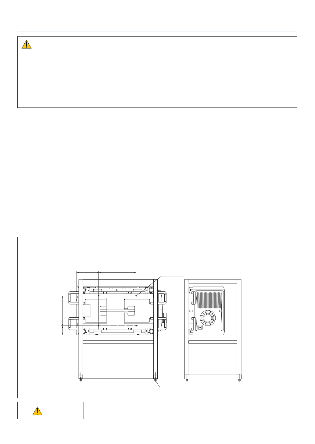
116
7. Appendix
Caution to the installation for the Tilt-free projection
•Donotinstalltheprojectorinthestateoffacingup/downorinclineddirectlyonaoorandatable.Iftheprojector
falls down, It may cause of malfunction, damage, human injury or hazardous laser radiation exposure. If the intake
vents are obstructed, the projector inside temperature will increase and it may cause of malfunction and re.
•Makesuretoproducethesupportmetalfortheprojectorastheceilingmountmetal.Pleaseasktheservice
company about the support metal production. (for a fee)
•Incaseyouneedtoinstalltheprojectorintiltedangle,pleaseinstalltheprojectorbysupportmetalsthathave
enough durability to support the projector for a long time.
Design and manufacturing conditions for a stand and a ceiling mount metal of the projector
Please hire an installation service provider (for a fee) to design and manufacture customized stand and ceiling mount
metal. Please ensure that the design complies with the following conditions:
•There are intake openings and exhaust openings on the side of the main unit, exhaust openings on the rear, intake
openings on the front, intake openings on the top side. Make sure that the design does not obstruct these open-
ings. Also make sure to secure enough space to allow easy removal of the lter cover for cleaning the lter.
•Removetheleveladjustersortheprojectorhandlesincasethesehitagainstthestand.Forremovingthelevel
adjuster, rotate the level adjuster itself, and for removing the handle, remove the handle fastening screws.
•Fixthestandontotheceilingmountscrewholes(4positions)ontheprojectorbottomface.
Dimensions of screw hole: for M8 screw Maximum depth 20 mm (Calculate the bolt length depending on the stand
design)
•Horizontaladjustmentmechanism(forexample,boltsandnutsin4places)
•Makesuretodesignthestandnotfallingovereasily.
•Makesureiftheprojectorisxedonthesurfacethathasenoughdurabilitytostandthewholeprojectorweight
(theprojectorweightincludingLVunit170kgplusthelensweight9kg,i.e.,179kgintotal)foralongtime.
Referential drawings for the portrait projection
* Figure illustrating the dimensions and conditions (not actual design blueprint).
320
433.4
131.8
540
[Side View] [Front View]
4 - M8 bolt
(Unit: mm)
Horizontal adjuster
CAUTION
•To carry the projector, a minimum of six persons are required. Be sure to rmly grip
the front and back handles, then move the projector.
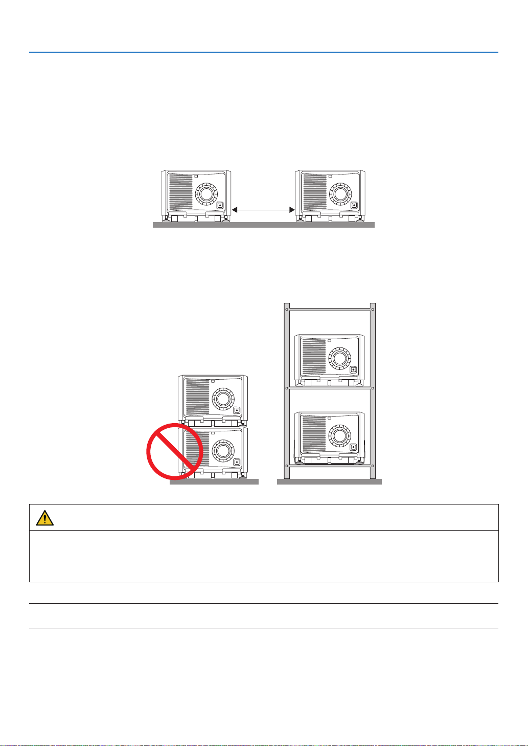
117
7. Appendix
7-7-4. Multi-Screen Projection
You can project two or four sources of images from the single projector at the same time. Another way is to use two
or more projectors aligned for displaying a larger image with a higher resolution.
For information on each setting up procedures, see the user’s manual.
[Note on Setting Up Two or More Projectors Aligned]
•Leavesufficientspaceontheleftandrightoftheprojectorsothattheintakeandexhaustventsoftheprojectorare
not obstructed. When the intake and exhaust vents are obstructed, the temperature inside the projector will rise
and this may result in a malfunction.
•Pleasedonotpileuptheprojectorsdirectlyontopofoneanotherwheninstallingthem.Whentheprojectorsare
piled up on top of one another, they may fall down, resulting in damage and failure.
The following installation is recommended when combining the installation of two projectors. Please leave sufficient
space on the left and right of the projector.
Cabinet
WARNING
Please request the retail store for special installation services such as when mounting the projector to the ceiling
or suspending from the ceiling using eye bolts. Never carry out the installation by yourself. The projector may fall
down and result in injury. Please use a sturdy cabinet that can withstand the weight of the projector for the instal-
lation. Please do not pile up the projectors directly on top of one another.
NOTE:
•Fortherangeoftheprojectiondistance,pleaserefertotheAppendix“Throwdistanceandscreensize”.(→page
6)
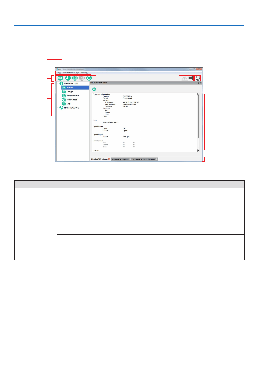
118
7. Appendix
7-8. Using the DCC’s functions
7-8-1. Description of the Sections in the screen
You can change the size of the window display by dragging.
Main window
Tool bar
Menu bar
Menu tree
Shortcut button Status display (status of light source and shutter)
Shield button
Tab display
Tool bar
Menu Submenu Description
File About DCC Displays the version information of the DCC.
Exit Terminates DCC.
Select Projector... Displays the Projector Select screen. (See page
55)
OptionAlways on Top Select whether the DCC screen is always displayed as the rst
screen. At activation, “Not display rst” is selected.
Not checked: The DCC screen is not displayed in the foreground.
Checked: The DCC screen is always displayed in the foreground.
Disp Local Time Sets the date and time for when logs are displayed using DCC.
Not checked: Uses universal coordinated time (UTC).
Checked: Uses the local time set in the projector main unit.
Language Select a language that is displayed on the menu.
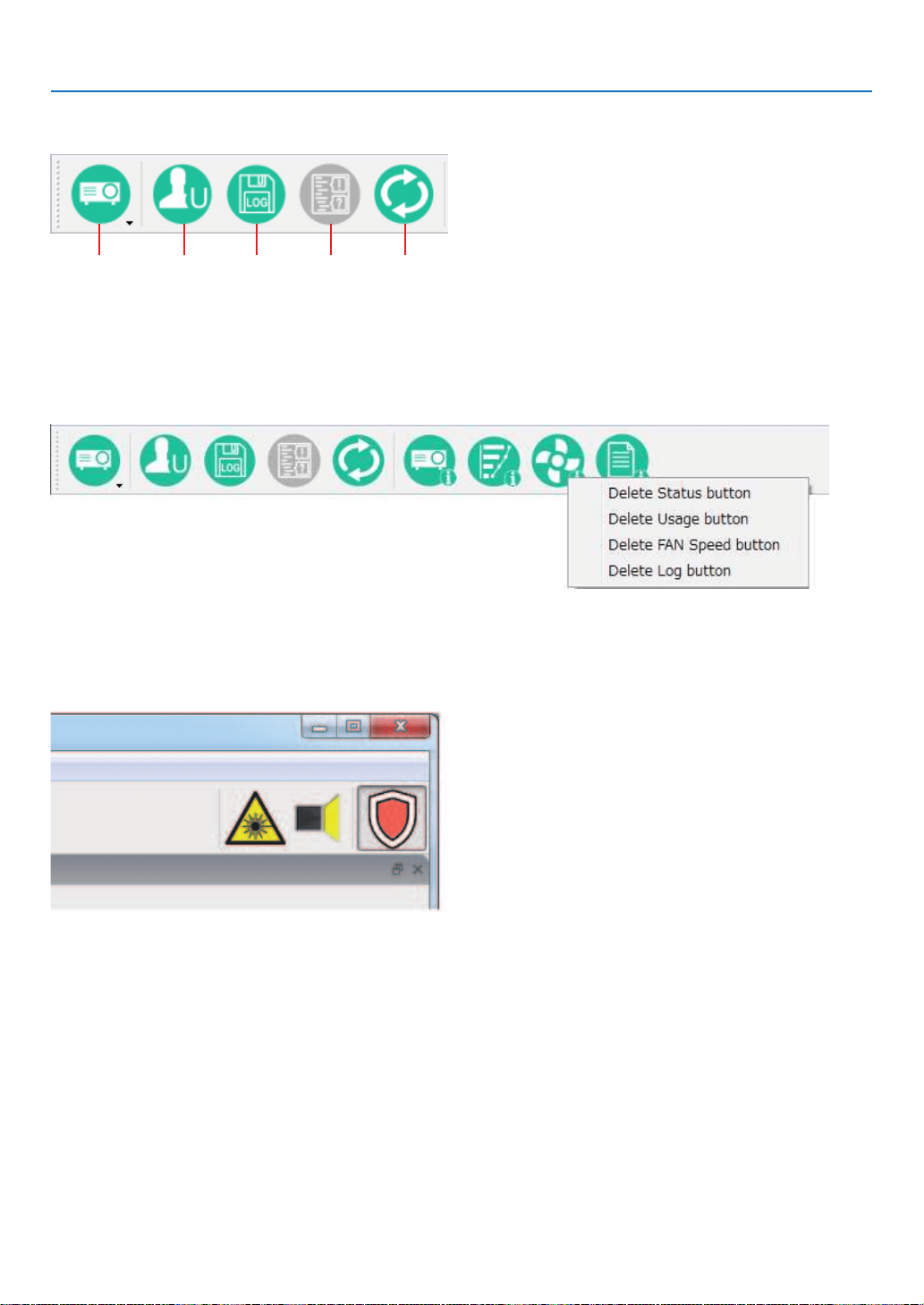
119
7. Appendix
Menu bar
The following menu buttons are displayed by default.
Select
Projector
Change
mode
RefreshLog Viewer *Create
log
* The function of Log Viewer is available on Service Mode only.
You can add menu buttons to the menu bar by dragging the menu buttons from the tree menu found on the left.
To remove menu buttons that you have added, right-click on the menu button you want to remove, then click “Delete”
menu.
“Shield” button
The DCC controls can be disabled by this button to prevent inadvertent operation (The “Shield” button is displayed
in orange).
Press the “Shield” button again to return to the original state.
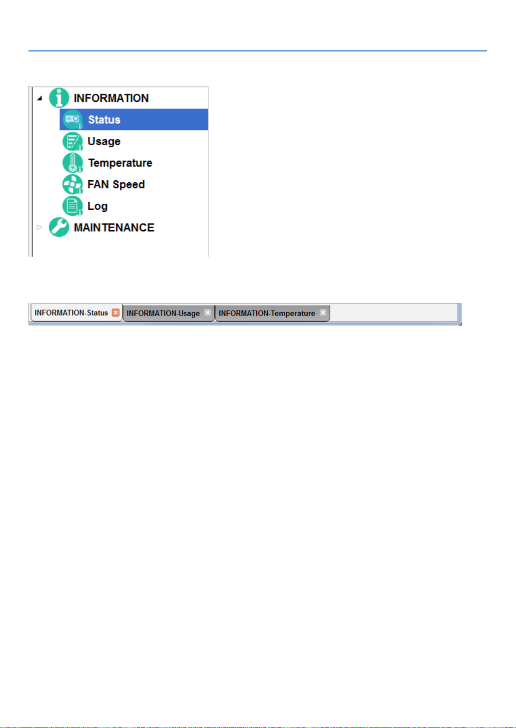
120
7. Appendix
Menu tree
The menu selected here appears on the right part of the main window.
Tab display
The windows displayed on the main window appear as tabs at the bottom of the screen, and you can change the
display by clicking on a tab. Click “x” to close a tab.
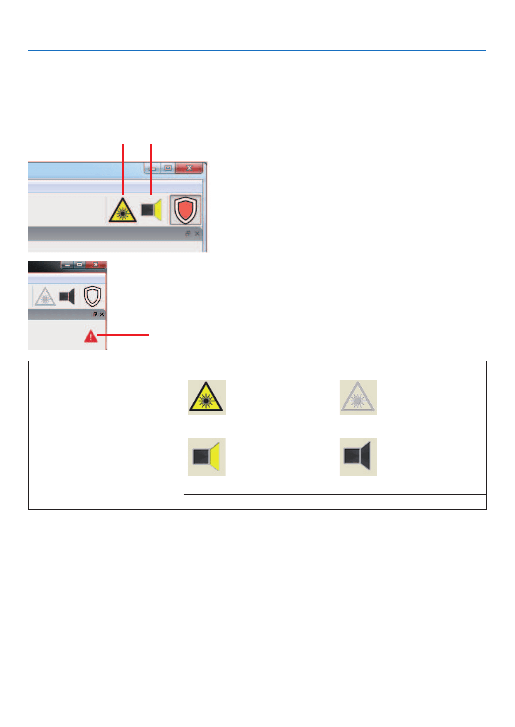
121
7. Appendix
Main window
The main window selected from the tree menu is displayed.
Multiple main windows can be displayed by dragging a tab out of the current window.
Status display
The status of the projector is displayed through a number of icons.
21
3
1. Laser warning icon Indicates whether the laser is illuminated or not (on or off).
(yellow):LaserlightON
(gray):LaserlightOFF
2. Shutter icon Displays the status of the shutter (open/closed).
(yellow): Shutter is open. (gray): Shutter is closed.
3. Error Status Icon Displays an error or warning.
“Error” is displayed in red, and “Warning” is orange.
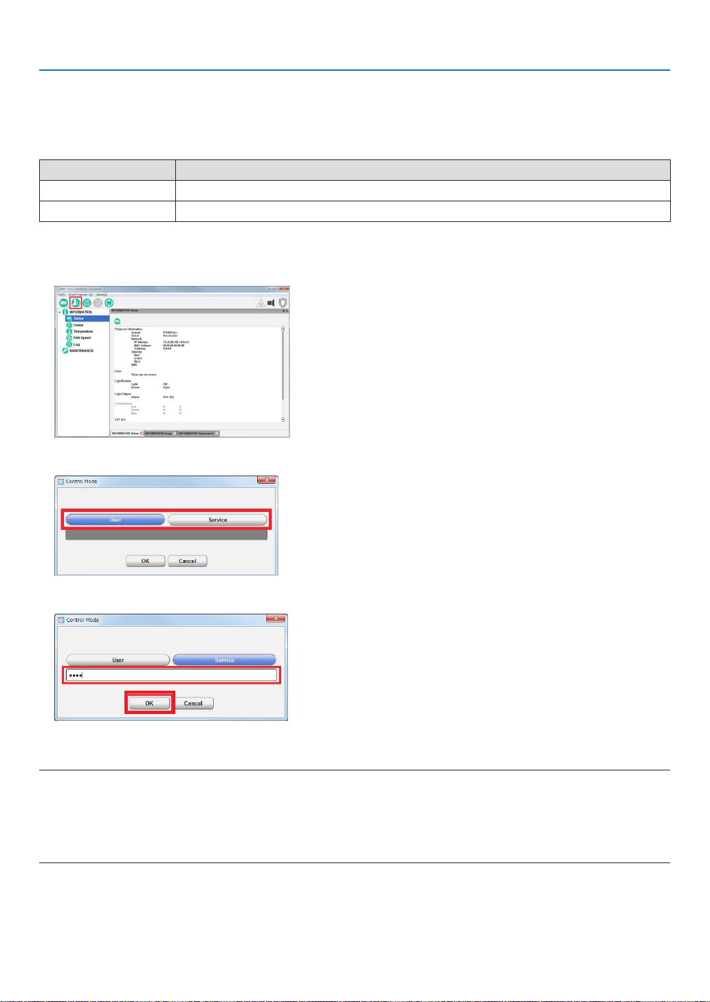
122
7. Appendix
7-8-2. Switching the operating mode
There are two menu modes available. The menu items that can be used differ depending on the mode.
When you click “Change mode ” on the menu bar, you can switch the mode. Dedicated passcodes need to be entered
in order to switch to Service mode.
Mode Description
User mode Menu for installation. (initial setting)
Service mode Menu for the service personnel.
1.
Click the “Change mode ” button on the menu bar.
The “Control Mode” screen appears.
2. Click the button of the mode to change.
3. Input the passcode and click “OK” button.
WhenchangingtotheUsermode,youdonotneedtoinputthepasscodeisnotneeded.
NOTE:
•Whenyouenterthepassword,payenoughattentiontopeoplearoundforthepasswordabuseprevention.
Ifyouhaveanxietythepasswordischeated,changethepasswordimmediately.
Beforeenteringthepassword,inspectthepasswordentrydevice(PC)foranyevidenceofphysicaltampering.Intheeventthat
anysuspiciousmarkingsarepresent,“DONOT”enterthepasswordandconsultwiththedistributor.
Alwaysstorethepasswordandprojectorinasafeplaceandneverdivulgethepasswordtounauthorizedentities.

123
7. Appendix
TIP:
•Whenthemodeischanged,the“Changemode”buttonisdisplayedasshownbelow.
•Usermode
•Servicemode

124
7. Appendix
7-8-3. Checking Information of the Projector and Logs
Clickoneofthebuttonsunderthe“INFORMATION”onthetreemenutodisplaytherespectivescreens.
TheINFORMATIONscreenismadeupofthefollowingsix screens that allow you to check information and various
logs of the projector main unit.
Status: ................... Allows you to check version information. You can also save the logs that are saved in the projector main
unit onto a computer.
Usage .................... Displays the usage times of the following: System/Light/Phosphor/Diffuser/Filter/Fan, etc.
Temperature ........... Displays the temperatures and atmospheric pressure of each part of the projector.
FAN Speed ............. Display the fan speeds of each part of the projector, as well as the Phosphor/Diffuser speeds.
Log ........................ Allows you to check the status of the main projector unit and various logs.
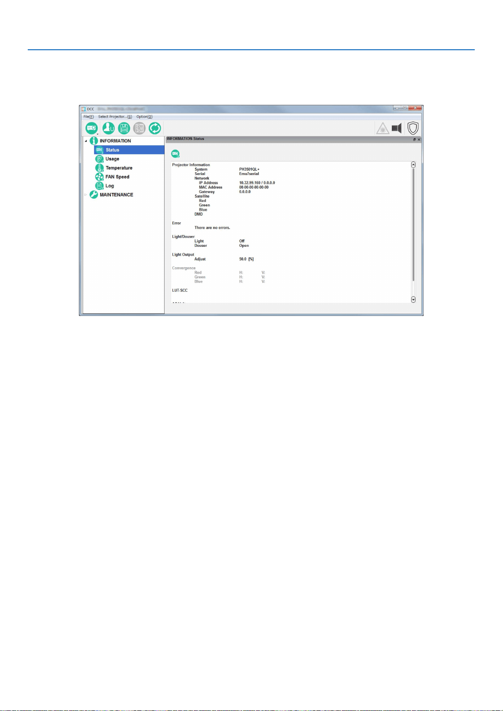
125
7. Appendix
INFORMATION Screen (Status)
Click the “STATUS” button from the menu bar to go to the STATUS screen.
From the STATUS screen, you can check the Projector setting status.
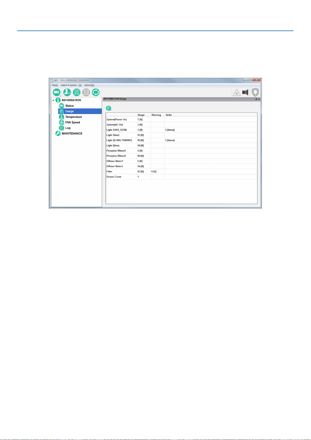
126
7. Appendix
INFORMATION Screen (Usage)
Clickthe“Usage”buttononthetreemenutodisplaytheINFORMATION-Usagescreen.
This screen allows you to check the usage times of the main projector unit, cooling fan, light source, phosphor, and
diffuser, as well as other information such as the air lter usage time and the number of times the light source has
been turned on.
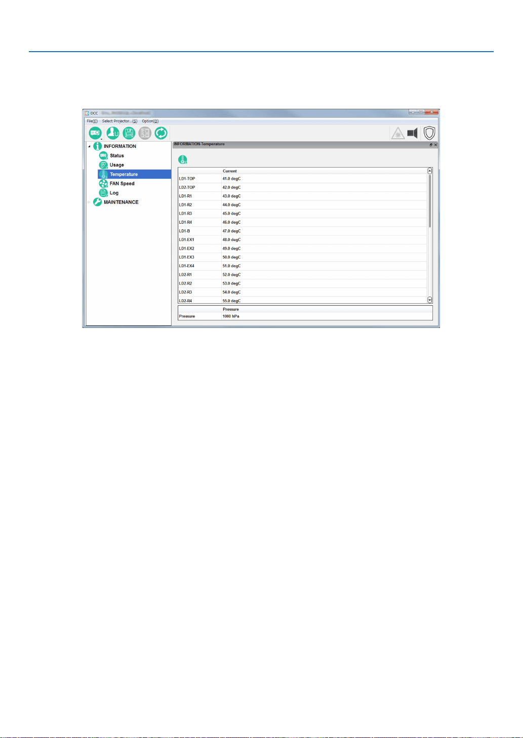
127
7. Appendix
INFORMATION Screen (Temperature)
Clickthe“Temperature”buttononthetreemenutodisplaytheINFORMATION-Temperaturescreen.Thisscreen
displays the temperatures and atmospheric pressure of each internal part of the projector.

128
7. Appendix
INFORMATION Screen (FAN Speed)
Clickthe“FANSpeed”buttononthetreemenutodisplaytheINFORMATION-FANSpeedscreen.Thisscreendisplays
the fan speeds of each part of the projector, as well as the Phosphor/Diffuser speeds.
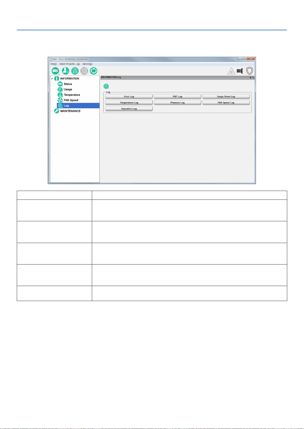
129
7. Appendix
INFORMATION Screen (Log)
Clickthe“Log”buttononthetreemenutodisplaytheINFORMATION-Logscreen.
You can check the various logs saved in the projector main unit from this screen.
“Error Log” button Displays the System Error Log screen.
“Usage Reset Log” button Displays the User Reset Log screen.
This displays various information about when the light source, fans, air lter, phos-
phor, and diffuser usage times were reset.
“Temperature Log” button Displays the Temperature Log screen.
This displays a record of the temperature from when the projector was turned on
until it was turned off (peak hold).
[Pressure Log] button Displays the Pressure Log screen.
This displays a record of the atmospheric pressure from when the projector was
turned on until it was turned off (peak hold).
“FAN Speed log” button Displays the FAN Speed Log screen.
This displays a record of the fan speed (minimum value) from when the power was
turned on until it was turned off (peak hold).
“OperationLog”buttonDisplaystheOperationLogscreen.
This displays a record of the operation of the projector.
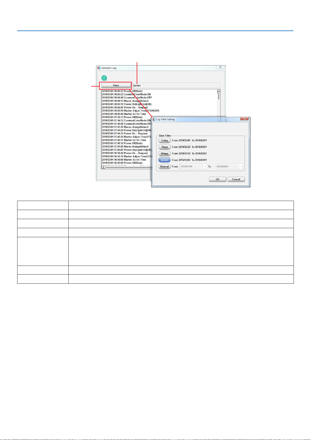
130
7. Appendix
Log Filtering Function
Click the “Filter” button to display the Log Filter Setting screen. You can set the period of logs to display using this screen.
Displays the current ltering settings.
“Filter” button
Today Displays only the log for today.
7days Displays the log for the last 7 days including today. (Default setting)
30days Displays the log for the last 30 days including today.
2years Displays the log for the last 2 years including today.
Manual Displays the log for the specied period (from From to To).
From:
Selects the start date of the period for which to display the logs.
To: Selects the end date of the period for which to display the logs.
Click “Today” in the calendar to set to today’s date.
“OK”buttonDisplays the logs that match the specied conditions.
“Cancel” button Cancels the settings and returns to the previous screen.
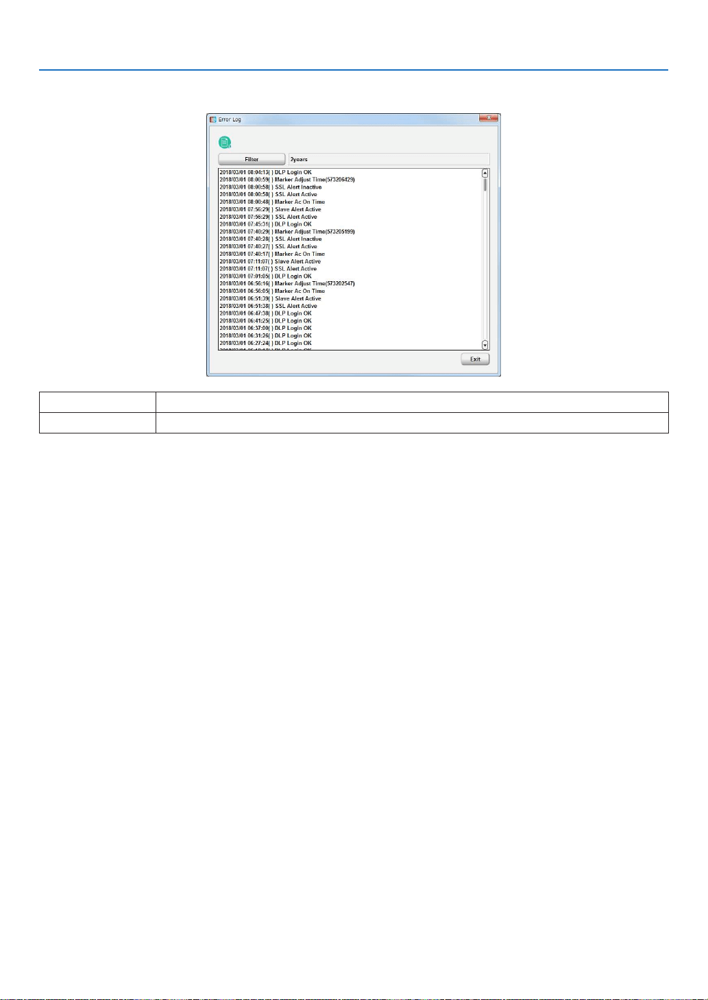
131
7. Appendix
System Error Log Screen
This screen displays a log inside the projector main unit errors.
“Filter” button Sets the period of the log to display.
“Exit” button Returns to the previous screen.
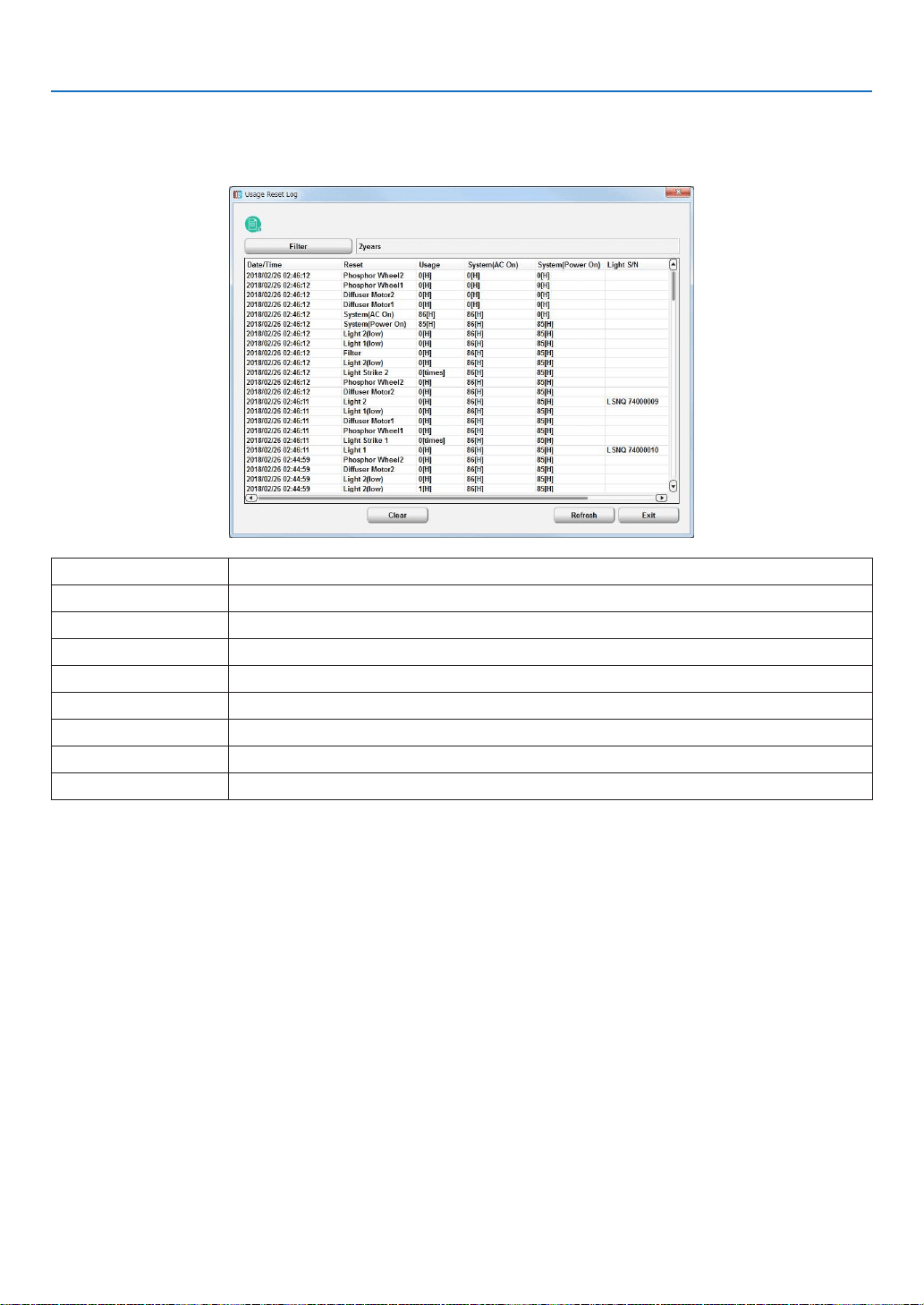
132
7. Appendix
Usage Reset Log Screen
When the usage times for the following items are reset, the value immediately before the reset is saved as log infor-
mation. This screen shows 64 items at most (64 items from the newest one are displayed).
•Light,Airlter,Fan,Phosphor,Diffuser
“Filter” Button Sets the period of the log to display.
Data/Time Displays the date and time.
Reset Displays the reset subject.
Usage Displays usage time prior to resetting.
System(ACOn)Displaystheprojectorusagetime(ACOn)priortoresetting.
System(PowerOn)Displaystheprojectorusagetime(PowerOn)priortoresetting.
“Clear” button Clears the usage reset log and closes the screen.
“Refresh” button Updates the displayed contents to the newest information.
“Exit” button Returns to the previous screen.
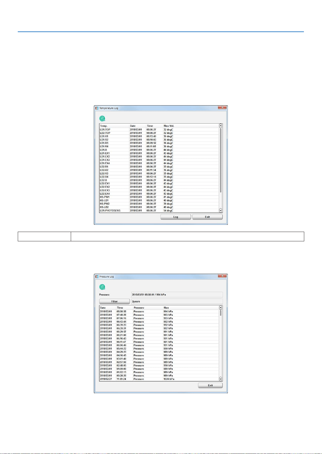
133
7. Appendix
Temperature Log Screen
This screen displays the maximum temperature recorded in the period from when the projector was turned on until
it was turned off.
Displays the maximum temperatures measured and dates and times for each item from when the power was last
turned on until now. The information that is saved in the log when the power is turned off is displayed in sequential
order in the Temperature Log detail screen. When saved as a log, information at the time when the log was recorded
(all temperatures, fan speeds, and light outputs within the projector) is also saved in addition to the maximum tem-
perature and date and time of each item.
•TemperatureLogdetailscreen
“Log” button Displays previous logs.
Pressure Log Screen
This screen displays the maximum pressure recorded in the period from when the projector was turned on until it
was turned off.
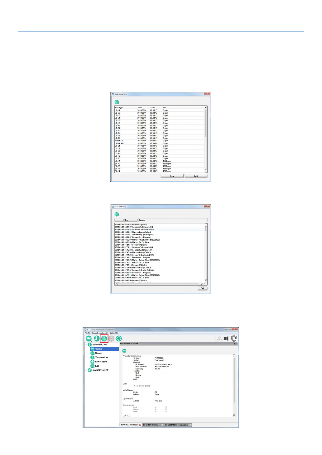
134
7. Appendix
FAN Speed Log Screen
This screen displays the minimum fan speeds recorded in the period from when the projector was turned on until it
was turned off.
Displays the minimum fan speeds measured and dates and times for each item from when the power was last turned
on until now. The information that is saved in the log when the power is turned off is displayed in sequential order in
the Fan Speed Log detail screen.
•FANSpeedLogdetailscreen
Operation Log Screen
This screen displays a record of the operation of the projector.
7-8-4. Creating logs
1. Click the “Create log” button on the menu bar.
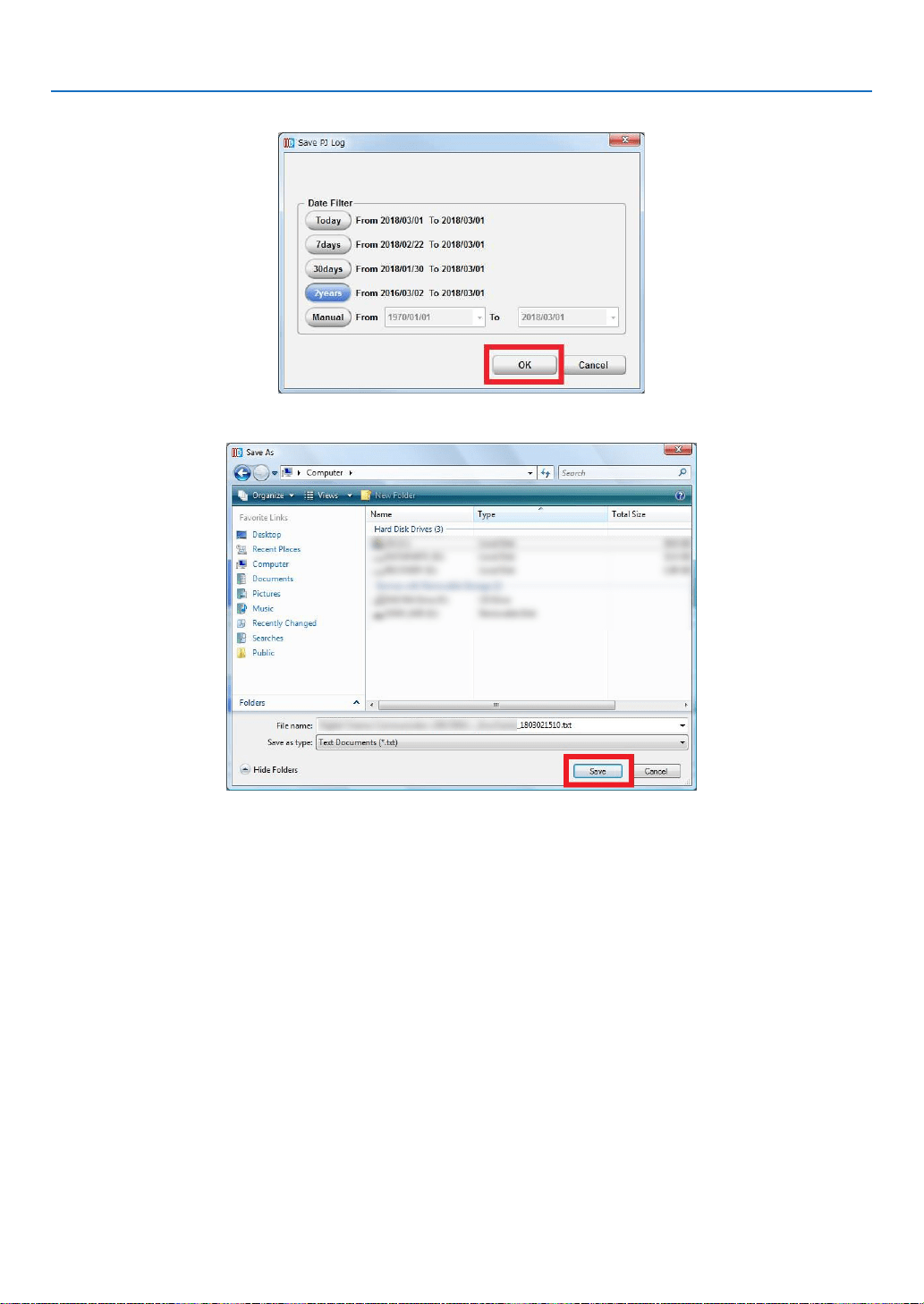
135
7. Appendix
2.Selectthelogacquisitionrangeandclickthe[OK]button.
3. Select where to save the log and click the [Save] button.
Log creation processing starts.
•Theprogressbarisdisplayedwhilethelogisbeingcreated.
•Oncetheloghasbeencreated,thenormalscreenreappears.

In Europe
NEC Display Solutions Europe GmbH
Address:
Landshuter Allee 12-14
D-80637 Munich, Germany
Telephone:+4989996990
Email: [email protected]
In North and South America
NEC Display Solutions of America, Inc.
Address:
500 Park Boulevard, Suite 1100,
Itasca, Illinois 60143 U.S.A.
Telephone: +1 800 836 0655
Email: [email protected]
In Oceania
Australia, DrGroup Global
Address:
Unit 3, 277-281 Sir Donald Bradman Drive,
DOWANDILLASPA5033
CUSTOMERCALLCENTRE:
Telephone: 1300 632 435
Email: [email protected]
NewZealand,DrGroupZN
Address:
28 Walls Road, Penrose,
Auckland,NewZealand
CUSTOMERCALLCENTRE:
Telephone:0508855911
Email: [email protected]
In Asia
NEC Display Solutions, Ltd.
Address:
686-1,Nishioi,Oi-Machi,
Ashigarakami-Gun, Kanagawa 258-0117, Japan
Telephone:+81465852369
NEC (China) Co., Ltd.
Address:
6F, Landmark diplomatic office building D2,
No.19EastRoad,ChaoyangDistrict,
Beijing 100600, R.P.C.
Telephone:010-59342706
NEC Hong Kong Ltd.
Address:
25/F, The Metropolis Tower, 10 Metropolis Drive,
Hunghom, Kowloon, Hong Kong
Telephone:+85223690335
NEC Taiwan Ltd.
Address:
7F, No. 167, SEC. 2, Nan King East Road,
Taipei,Taiwan,R.O.C.
Telephone: +886 2 8500 1710
NEC Asia Pacic Pte. Ltd.
Address:
80 Bendemeer Road,
#05-01/02 Hyux Innovation Centre,
Singapore339949
Telephone:+6567996188
NEC Corporation of Malaysia Sdn Bhd
Address:
Suite 20-01, Level 20,
The Gardens North Tower,
Mid Valley City, Lingkaran Syed Putra,
59200KualaLumpur
Telephone:+603-22996322
© NEC Display Solutions, Ltd. 2018
Ver. 2 7/18
