Loading ...

2
4 CHANNEL STEREO MODE
INPUTS
• Under the “INPUTS”, move the switch to either position of “2IN or 4IN” depending on how many
inputs you are using to run the amp, 2 or 4.
• If you are only using one single pair of RCA’s from your source, then plug them into the Channel 3+4
or (REAR) RCA inputs, and select “2IN”
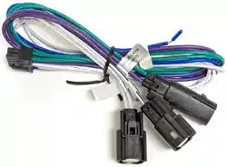
• If you are using the Harley Molex harness, then you are setting the switch to “2IN”
NOTE: FOR 2 CHANNEL INPUT USING THE RCA HARNESS (CH 1 & 2 INPUTS)
OR THE HARLEY HARNESS WITHOUT FACTORY REAR SPEAKERS:
You will need to use the 4 inch patch harness. Set switch to 2 IN and use input Channels 3 & 4
NORMAL/BRIDGED
• This switch should be set to “NORM”
SLOPE
• You can select the crossover slope you want for both channels, either a 6db/octave slope or a 12db/
octave slope.
• 12 db/octave is a sharper roll off slope, where the 6db/octave is more gradual roll off slope.
CHANNELS 1 & 2 CROSSOVER CONFIGURATION
• Channels 1+2 can be run in either Full Range, or in High Pass (HP) mode, using the bottom
row of controls. To run in Full Range mode, adjust the HP control down to the 10hz position.
• To run in HP mode, adjust the HP control to your desired HP frequency.
• Motorcycles normally use HP 120Hz.
CHANNELS 3 & 4 CROSSOVER CONFIGURATION
• You can select between Full Range (FR), Low Pass (LP), High Pass (HP), or Band Pass (BP) mode,
using the top row of controls.
• For FR, set MODE switch to HP, and adjust the HP control down to 10hz.
• For HP, set the MODE switch to HP, and adjust the HP control to set the HP frequency.
• For LP, set the MODE switch to LP. Adjust the HP control down to 10hz. Then adjust LP control to set
the LP frequency.
• For BP, set the MODE switch to LP, and adjust the LP control to the desired LP frequency. Adjust the
HP control to set HP frequency.
• Motorcycles normally use HP 120Hz.
GAIN CONTROL
• In this mode you will be using both gain controls to match your sources output level to your
amplifiers input.
SPEAKER OUTPUTS
• Following the wiring diagram in Figure 2B, wire your speakers to the appropriate output wires,
respecting the channels, and the + and – phasing.
Loading ...
Loading ...
Loading ...