1
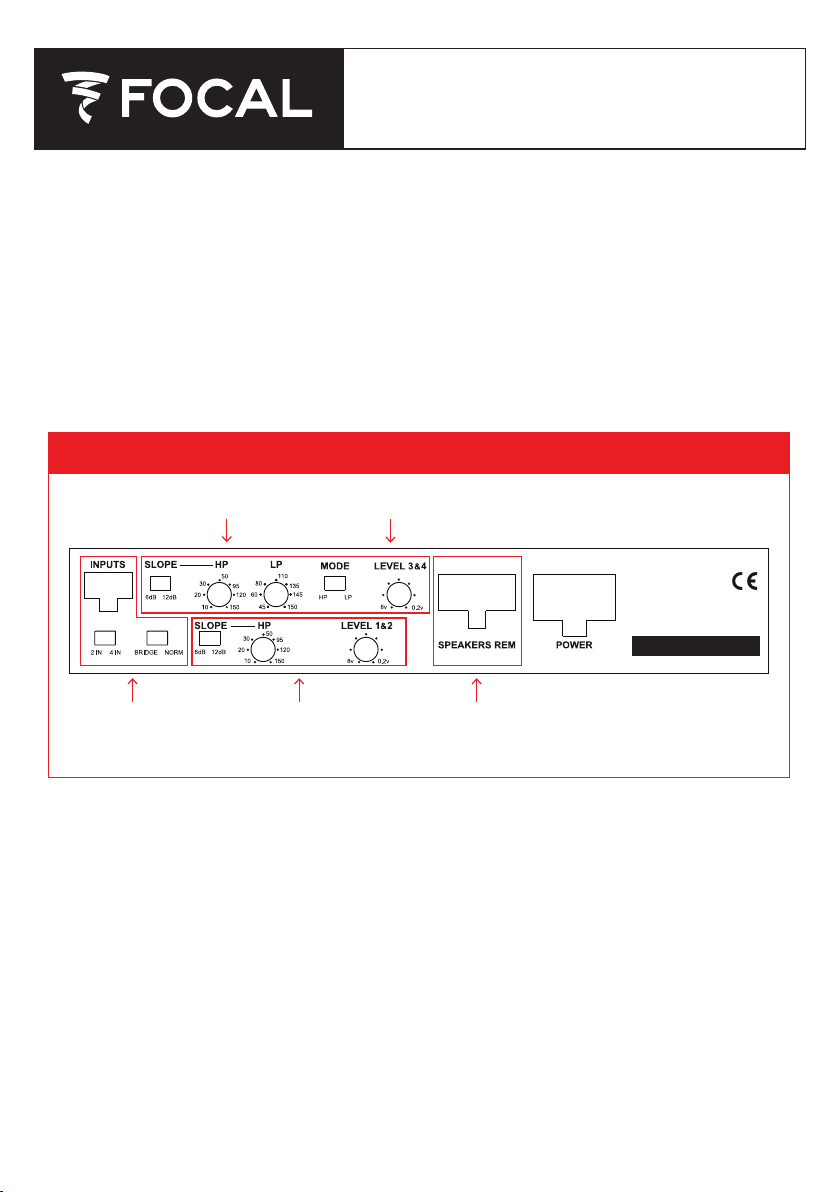
Shared Controls
(All Channels)
Ch 1+2 Controls Refer to Figures 2B, 3B, or 4B for wiring diagrams
Refer to Figures 2A, 3A, or 4A for control diagrams
Ch 3+4 Controls
Figure 1 | N
CONFIGURATIONS
These are the 3 basic configurations that you will be using when installing your Focal FDP
SPORT V2. Pick the mode you will be running, turn to the appropriate page, and follow the
instructions to make the correct amp adjustments.
• 4 Channel Stereo Mode (Page 2)
• 2 Channel Bridged Stereo Mode (Page 4)
• 3 Channel Stereo and Bridged Mono Mode (Page 6)
FDP SPORT V2: 4-CH MOTO & ALL-TERRAIN AMP
OPERATION / CONFIGURATION MANUAL
FDP SPORT
V2
avigating the FDP Sport V2 Controls

2
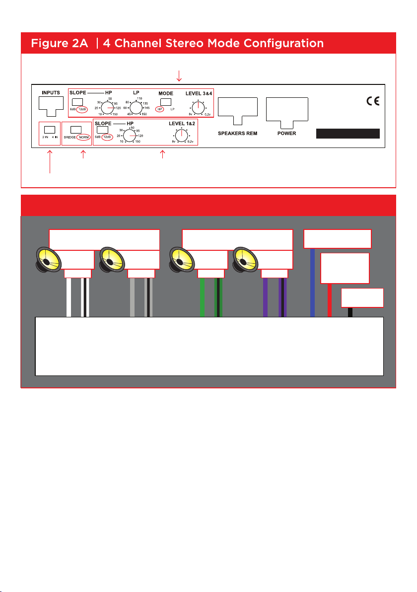
4 CHANNEL STEREO MODE
INPUTS
• Under the “INPUTS”, move the switch to either position of “2IN or 4IN” depending on how many
inputs you are using to run the amp, 2 or 4.
• If you are only using one single pair of RCA’s from your source, then plug them into the Channel 3+4
or (REAR) RCA inputs, and select “2IN”
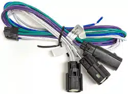
• If you are using the Harley Molex harness, then you are setting the switch to “2IN”
NOTE: FOR 2 CHANNEL INPUT USING THE RCA HARNESS (CH 1 & 2 INPUTS)
OR THE HARLEY HARNESS WITHOUT FACTORY REAR SPEAKERS:
You will need to use the 4 inch patch harness. Set switch to 2 IN and use input Channels 3 & 4
NORMAL/BRIDGED
• This switch should be set to “NORM”
SLOPE
• You can select the crossover slope you want for both channels, either a 6db/octave slope or a 12db/
octave slope.
• 12 db/octave is a sharper roll off slope, where the 6db/octave is more gradual roll off slope.
CHANNELS 1 & 2 CROSSOVER CONFIGURATION
• Channels 1+2 can be run in either Full Range, or in High Pass (HP) mode, using the bottom
row of controls. To run in Full Range mode, adjust the HP control down to the 10hz position.
• To run in HP mode, adjust the HP control to your desired HP frequency.
• Motorcycles normally use HP 120Hz.
CHANNELS 3 & 4 CROSSOVER CONFIGURATION
• You can select between Full Range (FR), Low Pass (LP), High Pass (HP), or Band Pass (BP) mode,
using the top row of controls.
• For FR, set MODE switch to HP, and adjust the HP control down to 10hz.
• For HP, set the MODE switch to HP, and adjust the HP control to set the HP frequency.
• For LP, set the MODE switch to LP. Adjust the HP control down to 10hz. Then adjust LP control to set
the LP frequency.
• For BP, set the MODE switch to LP, and adjust the LP control to the desired LP frequency. Adjust the
HP control to set HP frequency.
• Motorcycles normally use HP 120Hz.
GAIN CONTROL
• In this mode you will be using both gain controls to match your sources output level to your
amplifiers input.
SPEAKER OUTPUTS
• Following the wiring diagram in Figure 2B, wire your speakers to the appropriate output wires,
respecting the channels, and the + and – phasing.
3
Select “NORM” Front Channel 1+2 Adjustments
Select the amount of inputs you are using
Rear Channel 3+4 Adjustments
FRONT SPEAKERS
+– +–
REAR SPEAKERS
+– +–
BATTERY
50 AMP FUSE
GROUND
AMP TURN ON
FDP SPORT
LEFT
Ch. 1
RIGHT
Ch. 2
LEFT
Ch. 3
RIGHT
Ch. 4
Figure 2B | 4 Channel Stereo Mode Wiring Diagram
FDP SPORT
V2
FDP SPORT V2

4
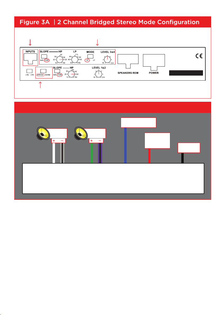
2 CHANNEL BRIDGED STEREO MODE
INPUTS
• You only need to use Rear INPUT Channels 3+4.
NORMAL/BRIDGED
• Set switch to “BRIDGED”
SLOPE
• Using the “SLOPE” switch on the top, select 12db for your crossover slope.
CHANNELS 3 & 4 CROSSOVER CONFIGURATION
• To adjust the crossovers, you will be looking at the controls on the top row. You will be able to choose
from Full Range (FR), High Pass (HP), Low Pass (LP), and Band Pass (BP)
• For FR, set MODE switch to HP, and adjust the HP control down to 10hz.
• For HP, set the MODE switch to HP, and adjust the HP control to set the HP frequency.
• For LP, set the MODE switch to LP. Adjust the HP control down to 10hz. Then adjust LP control to set
the LP frequency.
• For BP, set the MODE switch to LP, and adjust the LP control to the desired LP frequency. Adjust the
HP control to set HP frequency.
• Motorcycles normally use HP 120Hz.
GAIN CONTROL
• In this mode you will be using the “LEVEL 3+4” gain control to match your sources output level to
your amplifiers input.
SPEAKER OUTPUTS
• Following the wiring diagram in Figure 3B, wire your speakers to the appropriate output wires,
respecting the channels, and the + and – phasing.
5
LEFT
RIGHT
GROUND
BATTERY
50 AMP FUSE
AMP TURN ON
Select “BRIDGE”
2 Channel Bridged Mode AdjustmentsUse Rear Inputs 3+4
Figure 3B | 2 Channel Bridged Stereo Mode Wiring Diagram
FDP SPORT V2
FDP SPORT V2

6
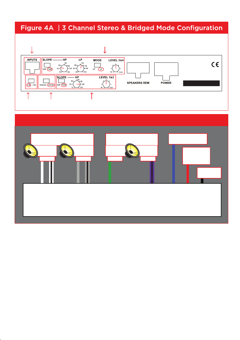
3 CHANNEL STEREO & BRIDGED MONO MODE
INPUTS
• When using 1 set of RCA inputs to run the 3 channels, you only need to use INPUT Channels 3+4.
Then switch the “2IN 4IN” switch to “2IN”
• If using 2 sets of RCA inputs to run this configuration, you will switch the “2IN 4IN” switch to “4IN”
NORMAL/BRIDGED
• Set switch to “NORM”
SLOPE
• Using the “SLOPE” switch on the top, select 12db for your crossover slope.
CHANNELS 1 & 2 CROSSOVER CONFIGURATION
• Channels 1+2 will be your HP Stereo channels.
• Adjust Channel 1+2 HP control to approximately 120Hz.
CHANNELS 3 & 4 CROSSOVER CONFIGURATION
• Channels 3+4 will be your LP Mono subwoofer channels
• Adjust Channel 3+4 LP control to approximately 120Hz.
• Adjust Channel 3+4 HP control to 10hz, unless you would like subsonic filter on your subwoofer.
In this case, you can adjust the control within the 20-30hz range.
GAIN CONTROL
• You will be using the “LEVEL 1+2” for your HP Stereo channels 1+2
• You will be using the “LEVEL 3+4” gain control for your LP Mono Subwoofer Channels
SPEAKER OUTPUTS
• Following the wiring diagram on the last page, wire your speakers to the appropriate output wires,
respecting the channels, and the + and – phasing. See 4B.
7
FRONT SPEAKERS
+– +–
SUBWOOFER
+– +–
GROUND
AMP TURN ON
BATTERY
50 AMP FUSE
FDP SPORT
LEFT
Ch. 1
RIGHT
Ch. 2
LEFT
Ch. 3
RIGHT
Ch. 4
Figure 4B | 3 Channel Stereo & Bridged Mode Wiring Diagram
Select NORM Use these controls to adjust your Stereo HP ChannelsSelect 2 IN
Use these controls to adjust your Mono LP Subwoofer ChannelUse Inputs 3+4
FDP SPORT
V2
FDP SPORT V2

8
TROUBLESHOOTING
> FOCAL SIGN DOES NOT LIGHT
1. Measure the voltage at the amplifier power terminal.
It should be between 12 and 15 volts.
2. Measure the voltage at the amplifier REM terminal.
It should be between 12 and 15 volts.
3. Is the REM wire connected?
4. Check your power and ground connections to be correct polarity + and - and
they are tight.
5. Check battery connections.
6. Check the fuse in the REM wire.
7. Check the 50 AMP fuse at battery.
8. Check fuses inside amplifier.
The fuses are inside the amp under he bottom panel.
The recommended ATC fuse size is two 25 amp.
To remove the bottom panel, turn amp upside down with the front panel facing
you. Remove the 3 screws on the bottom panel and the 2 upper front side
panel screws to expose the 2 fuses.
> AMPLIFIER BLOWS FUSE WHEN YOU TURN IT ON
1. Power and ground may be reversed.
Check + and - polarity at amplifier and at battery.

9
> FOCAL SIGN IS FLASHING
1. Is the amp very hot?
Wait a few minutes for it to cool down.
You need to get more fresh cool air to the amplifier.
Do not cover the amplifier or mount it flush into a hole.
2. If the amp is cold and the Focal sign is flashing, there is an internal fault.
3. Start your trouble shooting by removing the speaker harness.
4. Use an ohm meter and measure the speaker wires for short circuit.
> NO SOUND
1. Is the Focal sign light off or flashing?
2. Is the source radio on and is there a sound signal coming from the source
radio?
3. Use an ohm meter and measure the speaker wires for short circuit.
4. Check connections for small “wire whisker” that may be shorting between
amplifier terminals or speaker terminals.
5. Use an ohm meter and measure the speaker for short circuit.
6. Double check your connections to the source radio.
7. Are you using the correct source radio wires and are they plugged into the
correct amplifier RCA?
8. Double check your connections to the speakers and speaker crossovers.
9. Check that all amplifier switches are in the correct positions for your speaker
set up.
10. Check that HP & LP frequencies are set correctly for your speakers.
11. If little or no sound, make sure that you are NOT in BP (Band Pass) Mode,
with the crossover points overlapping or HP/LP frequency reversed.

10
WARRANTY INFORMATION
Focal America / Orca Design & Manufacturing supports their products and guarantees
them to be free of manufacturing defects for a period of 1 year (non-transferrable)
from the date of purchase, if purchased from an authorized retailer. This time period
is extended to 3 years (non-transferrable) from the date of purchase, if the amplifier is
purchased from and installed by an authorized retailer, and no alterations are made to
the installation or setup of the amplifier outside of the authorized retailer.
This manufacturing warranty does not extend to situations involving physical or
installation damage, misuse, abuse, or modification. If an amplifier malfunctions,
please return it to the authorized retailer from which the amplifier was purchased to
have the amplifier and/or installation inspected and to have the warranty period verified
from date of purchase.
The authorized dealer will then work with Focal America / Orca Design &
Manufacturing to obtain service, if necessary. If found to be a defect due to
manufacturing, the item will be repaired or replaced with a refurbished amplifier. The
amplifier will be returned to the authorized retailer when repairs are complete, so that
the dealer can return the amplifier to you, or reinstall the amplifier to maintain the
above mentioned warranty timeline.

11
TECHNICAL SPECIFICATIONS
4 x 150w RMS into 4 ohms @ 1% THD
4 x 200w RMS into 2 ohms @ 1% THD
2 x 400w RMS Bridged into 4 ohms @ 1% THD
Do NOT bridge into 2 ohms.
All power ratings are at 14.4v DC.
Frequency Response: 20 – 30KHz + or -, 1dB
Signal/Noise Ratio: 95dB (A)
Input Voltage for rated output unbalanced: 300mv – 8v
Input Voltage for rated output balanced: 600mv – 16v
Damping factor at 20Hz at 4 ohm: 75
Input Impedance unbalanced: 11K ohm
Input Impedance balanced: 22K ohm
LPF 45 – 150Hz 12dB/octave Linkwitz Riley
HPF 10 – 150Hz 12dB/octave Linkwitz Riley, Switchable to 6dB/octave Butterworth
Protection: DC, Short Circuit, Thermal, Polarity Reversal.
Dimensions: 8 1/4” (208mm) x 5” (127mm) x 1 5/8” (41mm)
Power Fuse: 50 Amps