
Loading ...
Loading ...
Loading ...
English
9
7
15
14
13
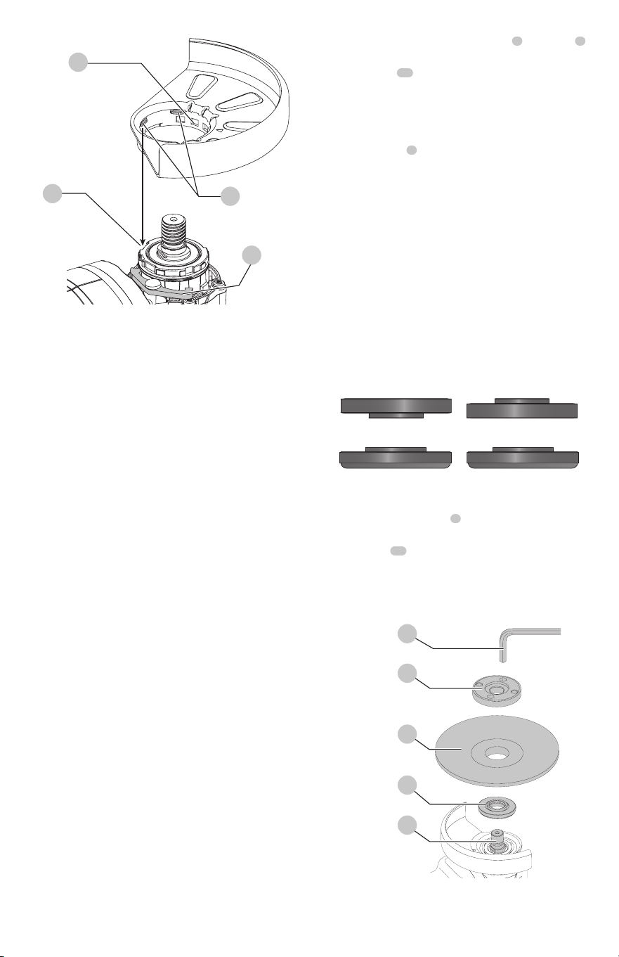
Fig. D
Flanges and Wheels
WARNING: To reduce the risk of serious personal
injury, turn unit off and disconnect it from
power source before making any adjustments or
removing/installing attachments or accessories.
An accidental start-up can cause injury.
WARNING: Accessories must be rated for at least
the speed recommended on the tool warning label.
Wheels and other accessories running over their
rated accessory speed may fly apart and cause injury.
Threaded accessories must have a 5/8"-11 hub. Every
unthreaded accessory must have a 7/8" (22 mm)
arbor hole. If it does not, it may have been designed
for a circular saw and should not be used. Use only
the accessories shown in the Accessories Chart of this
manual. Accessory ratings must always be above tool
speed as shown on tool nameplate.
WARNING: Handle and store all abrasive wheels
carefully to prevent damage from thermal shock, heat,
mechanical damage, etc. Store in a dry protected area
free from high humidity, freezing temperatures or
extreme temperature changes.
Mounting Non-Hubbed Wheels (Fig.E,F)
WARNING: Failure to properly seat the flanges and/or
wheel could result in serious injury (or damage to the
tool or wheel).
CAUTION: Included flanges must be used with
depressed center Type 27/42 grinding wheels and
Type1/41 cutting wheels. See the Accessories Chart
for more information.
WARNING: A closed, two-sided cutting wheel guard
is required when using abrasive cutting wheels or
diamond coated cutting wheels.
WARNING: Use of a damaged flange or guard or fail-
ure to use proper flange and guard can re sult in injury
due to wheel breakage and wheel contact. See the
Accessories Chart for more information.
1. Place the tool on a table, guard up.
2. Install the unthreaded backing flange
3
on spindle
1
with the raised center (pilot) facing the wheel.
3. Place wheel
17
against the backing flange,
centering the wheel on the raised center (pilot) of the
backingflange.
4. While depressing the spindle lock button and with the
raised center facing the wheel, thread the threaded
locking flange
4
on spindle.
nOTE: If the wheel you are installing is more than 1/8"
(3.17mm) thick, place the threaded locking flange on
the spindle so that the raised section (pilot) fits into the
center of the wheel. If the wheel you are installing is 1/8"
(3.17mm) thick or less, place the threaded locking flange
on the spindle so that the raised section (pilot) is not against
thewheel.
nOTE: If the wheel spins after the clamp nut is tightened,
check the orientation of the threaded clamp nut. If a thin
wheel is installed with the pilot on the clamp nut against
the wheel, it will spin because the height of the pilot
prevents the clamp nut from holding the wheel.
Fig. E
Over 1/8" (3.17mm)
wheels
Backing Flange
Locking flange
1/8" Or less (3.17mm)
wheels
Backing Flange
Locking flange
5. While depressing the spindle lock button, tighten the
threaded locking flange
4
:
a. Tighten the threaded locking flange using a
wrench
16
.
b. Tighten a keyless locking flange by hand. (Only use a
keyless locking flange if it is in perfect condition.)
6. To remove the wheel, depress the spindle lock button
and loosen the threaded locking flange.
Fig. F
16
4
17
3
1
Loading ...
Loading ...
Loading ...