1
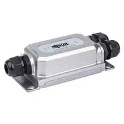
2-Port Gigabit Waterproof,
Hardened and Tamper-Proof
PoE Extender/Repeater
Model: NPOE-EXT-2X1G30
1111 W. 35th Street, Chicago, IL 60609 USA • tripplite.com/support
Copyright © 2021 Tripp Lite. All rights reserved.
Este manual está disponible en español en la página de Tripp Lite: tripplite.com
Ce manuel est disponible en français sur le site Web de Tripp Lite : tripplite.com
Dieses Handbuch ist in deutscher Sprache auf der Tripp Lite-Website verfügbar:
tripplite.com
WARRANTY REGISTRATION
Register your product today and be
automatically entered to win an ISOBAR
®
surge protector in our monthly drawing!
tripplite.com/warranty
Quick Start Guide
Русскоязычная версия настоящего руководства представлена на веб-сайте
компании Tripp Lite по адресу: tripplite.com
21-06-161-933F47-EN.indd 121-06-161-933F47-EN.indd 1 8/19/2021 11:12:06 AM8/19/2021 11:12:06 AM

2
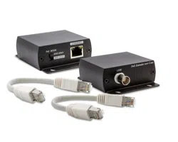
Package Includes
Product Features
• NPOE-EXT-2X1G30 2-Port Gigabit PoE Extender
• Wrench
• (x3) Waterproof Connectors
• Quick Start Guide
• Supports Power over Ethernet so no external power supply is needed
• Supports true 10/100/1000 Mbps data transmission and PoE power
supply distance up to 330 ft. (100 m)
• Includes one RJ45 95W PD input
• Two output ports have Power Sourcing Equipment (PSE) function, with
each port supporting up to 30W
• Industrial-quality housing handles harsh environmental conditions with
high stability and reliability
• IP67 waterproof rating
• IK10 impact protection rating against tampering and vandalism
• Complies with IEEE 802.3, 802.3u, 802.3ab, 802.3at, 802.3bt and
802.3x standards
• Unit supports plug-and-play operation with no additional configuration
needed
21-06-161-933F47-EN.indd 221-06-161-933F47-EN.indd 2 8/19/2021 11:12:06 AM8/19/2021 11:12:06 AM
3
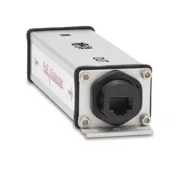
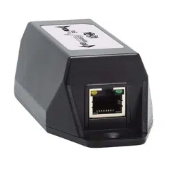
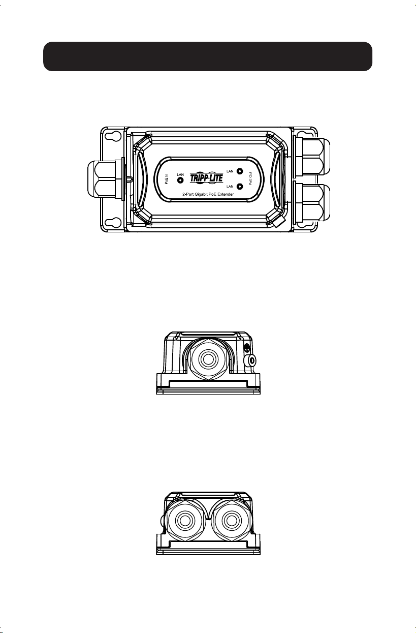
Hardware Description
Left Panel
The left panel includes the input port (PoE In) and grounding column with
standard network Cat5e cable (line diameter 5.5 mm).
Front Panel
The front panel includes the PSE output port, input port and LED indicator.
Right Panel
The right panel includes the output port (PoE Out), to be used with a
standard network Cat5e cable.
21-06-161-933F47-EN.indd 321-06-161-933F47-EN.indd 3 8/19/2021 11:12:06 AM8/19/2021 11:12:06 AM
4
Installation
Carefully read and follow all instructions to avoid device damage and security
threats that could result from incorrect installation.
• The nuts of the waterproof joint should be tightened fully to the joint threads
and fit level to the hexagon plane to prevent water from
damaging your equipment
• To avoid damage, do not place the unit on an unstable surface
• Make sure the operating voltage is the same one labeled on the unit
• To avoid the risk of electrical shocks, do not open the chassis while the unit
is operating or when electrical hazards are present
Desktop Installation
To install the unit on a desktop, place the bottom side (shown below) of the
unit on a stable, solid surface.
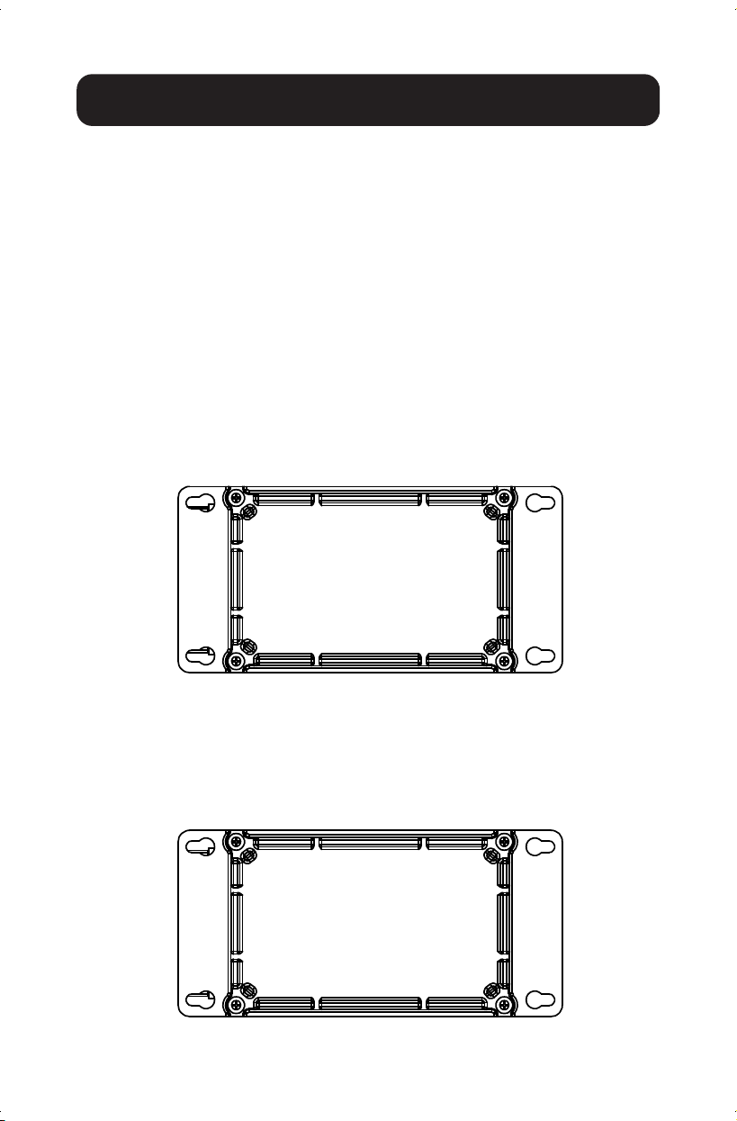
Wall-Mounted Installation
1.
Fix four screws
(not included)
on the wall and turn the unit upside down.
2. Align the four fixing holes of the unit as shown below and mount the unit
on the screws.
21-06-161-933F47-EN.indd 421-06-161-933F47-EN.indd 4 8/19/2021 11:12:07 AM8/19/2021 11:12:07 AM
5
Installation
Single Extender Installation
Note: Prior to connecting the RJ45 cable to input/output ports, install the
included cable glands onto the cable. Refer to Cable Wire and Crimp
Steps below.
1. Using a Cat5e/6 cable (up to 328 ft. / 100 m long), connect your powered
source device (such as a PoE switch) into the “IN” port on the unit.
2. Using another Cat5e/6 cable (up to 328 ft. / 100 m long), connect your
remote PoE powered device (PD), such as a VoIP or IP surveillance camera,
into the “OUT” port on the unit.
Notes:
• Your PoE source must meet or exceed IEEE 802.3at / 802.3af standards.
• When power is required, the power source (e.g. midspan or PoE injector)
must be installed between the Ethernet switch (non-PoE source) and the
first NPOE-EXT-2X1G30 extender.
• If you are installing an injector and a splitter, they each need to support
60 to 90W.
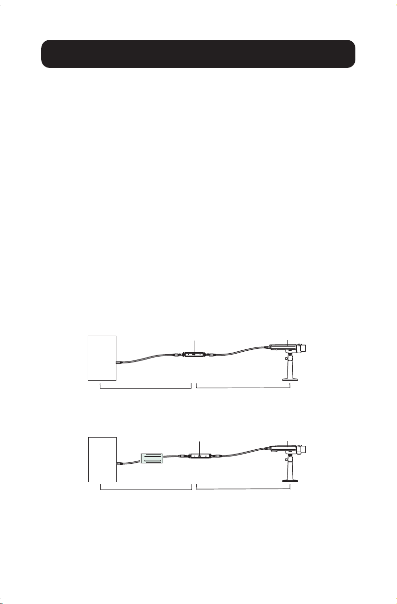
Single Extender Installation Diagram
Single Extender Installation with Midspan Diagram
CameraPoE Extender
PoE
Switch
Max 328 ft. (100 m) Max 328 ft. (100 m)
CameraPoE Extender
Switch
(Non-PoE)
Midspan
Max 328 ft. (100 m) Max 328 ft. (100 m)
21-06-161-933F47-EN.indd 521-06-161-933F47-EN.indd 5 8/19/2021 11:12:07 AM8/19/2021 11:12:07 AM
6
Installation
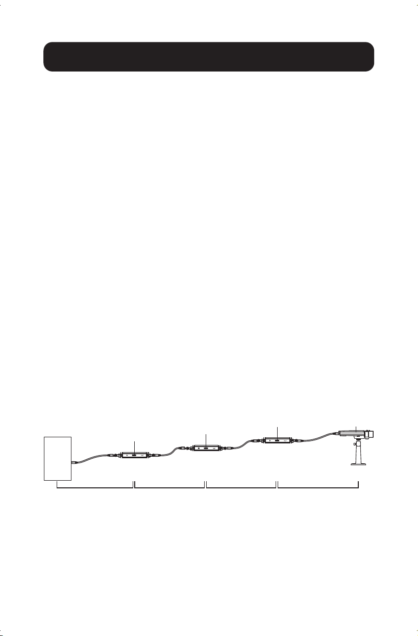
Multiple Extender Installation
Notes:
• You may only cascade three PoE extender units up to 1312 ft. (400 m)
in a single installation.
• Prior to connecting the RJ45 cable to input/output ports, install the
included cable glands onto the cable. Refer to Cable Wire and Crimp
Steps below.
1. Using a Cat5e/6 cable (up to 328 ft. / 100 m long), connect your
powered source device (such as a PoE switch) into the “IN” port on
the unit.
2. Using another Cat5e/6 cable (up to 328 ft. / 100 m long), connect the
“OUT” port of the first extender to the “IN” port of the second extender.
3. Repeat Step 2 up to two more times for each additional PoE extender
you add, or connect your remote PoE powered device (PD) to the “OUT”
port of the second PoE extender.
Notes:
• The third PoE extender will only supply IEEE 802.3af up to 7W.
• Your PoE source must meet or exceed IEEE 802.3at standards.
Multi-Extender Installation Diagram
Camera
PoE Extender
PoE Extender
PoE Extender
PoE
Switch
Max 328 ft. (100 m) Max 328 ft. (100 m) Max 328 ft. (100 m) Max 328 ft. (100 m)
21-06-161-933F47-EN.indd 621-06-161-933F47-EN.indd 6 8/19/2021 11:12:07 AM8/19/2021 11:12:07 AM
7
Installation
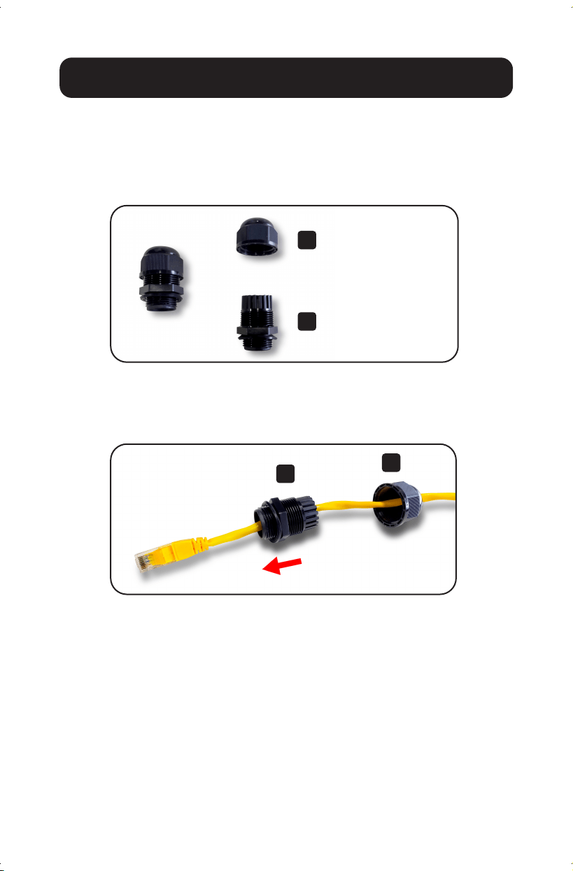
Cable Wire and Crimp Steps
Installing Cable Gland with RJ45 UTP Cable
Step 1: Disassemble the cable gland as shown below:
Step 2: Slip the Ethernet cable through the clamping nut and
gland body. Tighten the clamping nut and the body to
make the two parts into one complete cable gland.
A
A
B
B
Clamping Nut
Body (with washer)
21-06-161-933F47-EN.indd 721-06-161-933F47-EN.indd 7 8/19/2021 11:12:08 AM8/19/2021 11:12:08 AM
8
Installation
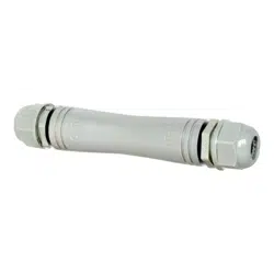
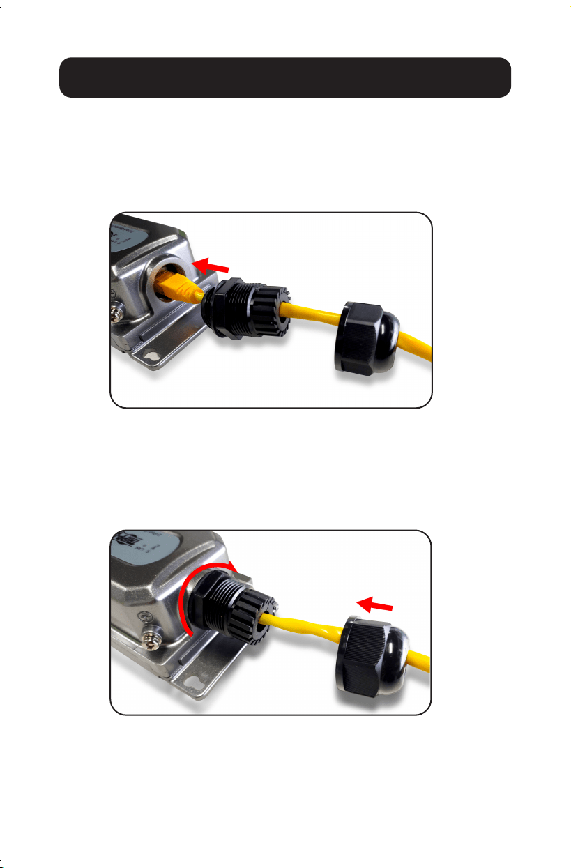
Connecting Waterproof Cable Kit
to the Outdoor PoE Extender
Step 1: Insert the RJ45 connector into the connector of the
PoE++ In Port.
Step 2: Turn clockwise to tighten the gland body with the
Outdoor PoE Extender.
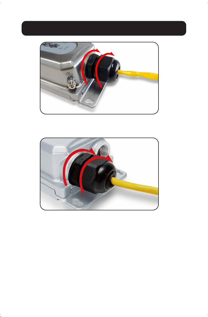
Step 3: Attach the clamping nut to the cable gland to
complete the cable assembly.
21-06-161-933F47-EN.indd 821-06-161-933F47-EN.indd 8 8/19/2021 11:12:09 AM8/19/2021 11:12:09 AM
9
Installation
Step 4: Repeat Steps 1 to 3 for two PoE+ Out Ports
21-06-161-933F47-EN.indd 921-06-161-933F47-EN.indd 9 8/19/2021 11:12:10 AM8/19/2021 11:12:10 AM

10
Model
NPOE-EXT-2X1G30
Standard
IEEE802.3, IEEE802.3u, IEEE802.3ab,
IEEE802.3x, IEEE80 2.3af , IEEE802.3at,
IEEE802.3bt
Ports
PoE In Port: 1 x 10/100/1000 Mbps RJ45
PoE Out Port: 2 x 10/100/1000 Mbps RJ45
Network Media (Cable)
10BASE - T: UTP category 3, 4, 5 cable (≤100m)
100BASE -TX: UTP category 5, 5e cable (≤100m)
1000BASE -TX: UTP category 5e cable (≤100m)
LED Color
Green
LED Functions
Off: No device is connected to the
corresponding port
Illuminated: Indicates the link through that port is
successfully established at 10/100/1000Mbps.
Blinking: Transmitting data and power
Dimensions
5.9 x 2.9 x 1.7 in. (150 x 73 x 44 mm)
Weight
0.93 lbs. (0.42 kg)
PoE Ports
2
Power Supply
Power over Ethernet (PoE)
PD Port Input
95W Max
PoE Power Output
48-55V DC Max 30W per port
Operating Temperature Range
-4° to 140°F (-20° to 60°C)
Storage Temperature Range
-40° to 176°F (-40° to 80°C)
Operating Humidity Range
10 to 90% RH, non-condensing
Storage Humidity Range
5 to 90% RH, non-condensing
Surge Protection
Differential Mode: ± 4KV
Common Mode: ± 6KV
MTBF
> 50,000 hours
Electrostatic Standard
Contact: 6KV
Air: 8KV
Weather Rating
IP67
Impact Protection Rating
IK10
Specifications
21-06-161-933F47-EN.indd 1021-06-161-933F47-EN.indd 10 8/19/2021 11:12:10 AM8/19/2021 11:12:10 AM

11
Warranty and Product Registration
3-Year Limited Warranty
Tripp Lite warrants its products to be free from defects in materials and workmanship for a period of three
(3) years from the date of initial purchase. Tripp Lite’s obligation under this warranty is limited to repairing
or replacing (at its sole option) any such defective products. To obtain service under this warranty, you must
obtain a Returned Material Authorization (RMA) number from Tripp Lite or an authorized Tripp Lite service
center. Products must be returned to Tripp Lite or an authorized Tripp Lite service center with transportation
charges prepaid and must be accompanied by a brief description of the problem encountered and proof
of date and place of purchase. This warranty does not apply to equipment, which has been damaged by
accident, negligence or misapplication or has been altered or modified in any way.
EXCEPT AS PROVIDED HEREIN, Tripp Lite MAKES NO WARRANTIES, EXPRESS OR IMPLIED, INCLUDING
WARRANTIES OF MERCHANTABILITY AND FITNESS FOR A PARTICULAR PURPOSE. Some states do not
permit limitation or exclusion of implied warranties; therefore, the aforesaid limitation(s) or exclusion(s) may
not apply to the purchaser.
EXCEPT AS PROVIDED ABOVE, IN NO EVENT WILL Tripp Lite BE LIABLE FOR DIRECT, INDIRECT, SPECIAL,
INCIDENTAL OR CONSEQUENTIAL DAMAGES ARISING OUT OF THE USE OF THIS PRODUCT, EVEN IF
ADVISED OF THE POSSIBILITY OF SUCH DAMAGE. Specifically, Tripp Lite is not liable for any costs, such as
lost profits or revenue, loss of equipment, loss of use of equipment, loss of software, loss of data, costs of
substitutes, claims by third parties, or otherwise.
PRODUCT REGISTRATION
Visit tripplite.com/warranty today to register your new Tripp Lite product. You’ll be automatically entered into
a drawing for a chance to win a FREE Tripp Lite product!
** No purchase necessary. Void where prohibited. Some restrictions apply. Open to U.S. residents only. See tripplite.com for
details.
FCC Notice, Class B
This device complies with part 15 of the FCC Rules. Operation is subject to the following two conditions: (1)
This device may not cause harmful interference, and (2) this device must accept any interference received,
including interference that may cause undesired operation.
Note: This equipment has been tested and found to comply with the limits for a Class B digital device,
pursuant to part 15 of the FCC Rules. These limits are designed to provide reasonable protection against
harmful interference in a residential installation. This equipment generates, uses and can radiate radio
frequency energy and, if not installed and used in accordance with the instructions, may cause harmful
interference to radio communications. However, there is no guarantee that interference will not occur in a
particular installation. If this equipment does cause harmful interference to radio or television reception,
which can be determined by turning the equipment off and on, the user is encouraged to try to correct the
interference by one or more of the following measures:
• Reorient or relocate the receiving antenna.
• Increase the separation between the equipment and receiver.
• Connect the equipment into an outlet on a circuit different from that to which
the receiver is connected.
• Consult the dealer or an experienced radio/TV technician for help.
Any changes or modifications to this equipment not expressly approved by Tripp Lite could void the user’s
authority to operate this equipment.
WEEE Compliance Information for Tripp Lite Customers and Recyclers (European Union)
Under the Waste Electrical and Electronic Equipment (WEEE) Directive
and implementing regulations, when customers buy new electrical and electronic equipment from
Tripp Lite they are entitled to:
• Send old equipment for recycling on a one-for-one, like-for-like basis
(this varies depending on the country)
• Send the new equipment back for recycling when this ultimately
becomes waste
21-06-161-933F47-EN.indd 1121-06-161-933F47-EN.indd 11 8/19/2021 11:12:10 AM8/19/2021 11:12:10 AM

12
1111 W. 35th Street, Chicago, IL 60609 USA • tripplite.com/support
21-06-161 933F47_RevX1
Warranty and Product Registration
Use of this equipment in life support applications where failure of this equipment can reasonably be
expected to cause the failure of the life support equipment or to significantly affect its safety or effectiveness
is not recommended.
Tripp Lite has a policy of continuous improvement. Specifications are subject to change without notice.
Photos and illustrations may differ slightly from actual products.
21-06-161-933F47-EN.indd 1221-06-161-933F47-EN.indd 12 8/19/2021 11:12:10 AM8/19/2021 11:12:10 AM