

PoE12-3PD User’s Guide
2
IMPORTANT!
READ CAREFULLY BEFORE USE.
KEEP THIS GUIDE FOR FUTURE REFERENCE.
Screenshots and graphics in this book may differ slightly from your product due to differences in product
features or web configurator brand style. Every effort has been made to ensure that the information in
this manual is accurate.
Note: The version number on the cover page refers to the PoE12-3PD’s latest firmware
Related Documentation
•Quick Start Guide
The Quick Start Guide shows how to connect the PoE12-3PD.
• The Nebula Control Center help portal
Go to https://nebula.zyxel.com/ to register the PoE12-3PD to the NCC.
• Nebula Control Center (NCC) User’s Guide
Go to https://nebula.zyxel.com/ to get the User’s Guide on how to manage the PoE12-3PD using
Nebula.
•More Information
Go to support.zyxel.com to find other information on the PoE12-3PD
.
Document Conventions
PoE12-3PD User’s Guide
3
Document Conventions
Warnings and Notes
These are how warnings and notes are shown in this guide.
Warnings tell you about things that could harm you or your device.
Note: Notes tell you other important information (for example, other things you may need to
configure or helpful tips) or recommendations.
Syntax Conventions
• The model may be referred to as the “PoE12-3PD” in this guide.
• Product labels, screen names, field labels are all in bold font.
• A right angle bracket ( > ) within a screen name denotes a mouse click. For example, Maintenance >
Log means you first click Maintenance in the navigation panel, then the Log tab to get to that screen.
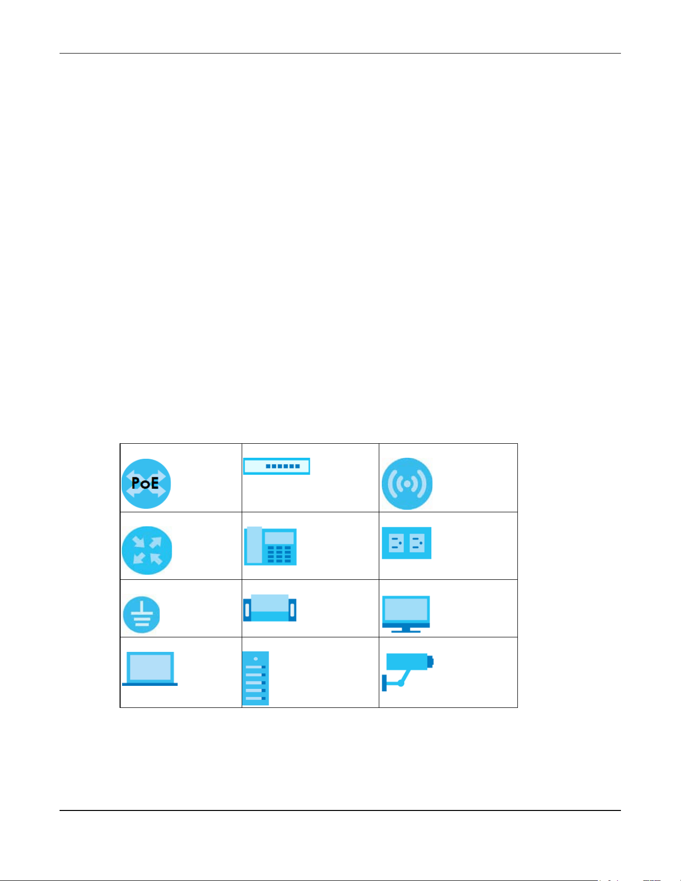
Icons Used in Figures
Figures in this user guide may use the following generic icons. The PoE12-3PD icon is not an exact
representation of your device.
PoE12-3PD Generic PoE Switch Wireless Router / Access Point
Generic Router IP Phone Power Outlet
Grounding Surge Protector Desktop
Laptop Server IP Camera

Contents Overview
PoE12-3PD User’s Guide
4
Contents Overview
User’s Guide ........................................................................................................................................7
Introduction ............................................................................................................................................. 8
Hardware .............................................................................................................................................. 20
Technical Reference ........................................................................................................................28
Web Configurator ................................................................................................................................. 29
Dashboard ............................................................................................................................................ 31
Maintenance ........................................................................................................................................ 38
Troubleshooting .................................................................................................................................... 43

Table of Contents
PoE12-3PD User’s Guide
5
Table of Contents
Part I: User’s Guide............................................................................................7
Chapter 1
Introduction ..........................................................................................................................................8
1.1 Overview ........................................................................................................................................... 8
1.1.1 Power over Ethernet (PoE) Example Application ................................................................ 8
1.2 Features ............................................................................................................................................. 9
1.2.1 Power over Ethernet (PoE) ..................................................................................................... 9
1.3 How to Manage your PoE12-3PD ................................................................................................. 10
1.4 NCC Management ........................................................................................................................ 10
1.4.1 NCC Web Portal .................................................................................................................... 12
1.4.2 Nebula Mobile App .............................................................................................................. 15
1.5 ZON Utility ......................................................................................................................................... 15
1.5.1 Requirements ......................................................................................................................... 15
1.5.2 Run the ZON Utility ................................................................................................................. 16
1.6 Good Habits for Managing the PoE12-3PD ................................................................................. 19
Chapter 2
Hardware ...........................................................................................................................................20
2.1 Port Connections ............................................................................................................................ 20
2.2 Grounding and Surge Protection ................................................................................................. 21
2.2.1 Grounding .............................................................................................................................. 21
2.2.2 Surge Protection .................................................................................................................... 22
2.3 Power Connection ......................................................................................................................... 23
2.4 Mounting ......................................................................................................................................... 23
2.5 LEDs .................................................................................................................................................. 24
2.6 Reset Button .................................................................................................................................... 26
Part II: Technical Reference...........................................................................28
Chapter 3
Web Configurator...............................................................................................................................29
3.1 Overview ......................................................................................................................................... 29
3.2 System Login .................................................................................................................................... 29
Chapter 4
Dashboard..........................................................................................................................................31

Table of Contents
PoE12-3PD User’s Guide
6
4.1 Dashboard ...................................................................................................................................... 31
4.2 Edit Dashboard ............................................................................................................................... 33
4.2.1 Network .................................................................................................................................. 33
4.2.2 Date/Time .............................................................................................................................. 35
4.2.3 Port Settings ........................................................................................................................... 37
Chapter 5
Maintenance......................................................................................................................................38
5.1 What You Can Do in This Chapter ................................................................................................ 38
5.2 Access Management Screen ....................................................................................................... 38
5.3 Change Password .......................................................................................................................... 39
5.4 Firmware Upgrade .......................................................................................................................... 39
5.5 Log .................................................................................................................................................... 40
5.6 Reboot ............................................................................................................................................. 41
5.6.1 What You Need To Know ..................................................................................................... 42
5.6.2 Reboot Screen ...................................................................................................................... 42
Chapter 6
Troubleshooting..................................................................................................................................43
6.1 Power, Hardware Connections, and LEDs ................................................................................... 43
6.2 Improper Network Cabling and Topology .................................................................................. 44
Appendix A Customer Support ....................................................................................................... 45
Appendix B Legal Information......................................................................................................... 50
Index...................................................................................................................................................55

7
PART I
User’s Guide
PoE12-3PD User’s Guide
1
CHAPTER 19
Introduction
19.1 Overview
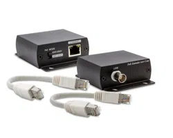
The PoE12-3PD is a 4-port PoE extender that extends Gigabit data and IEEE 802.3at/802.3af PoE (Power
over Ethernet) through standard 100-meter (328 feet) Cat5e cables.
The PoE12-3PD is installed between a PoE switch or PoE injector and the Powered Devices (PDs). The
PoE12-3PD is powered by a PoE switch or PoE injector through the UPLINK port over an Ethernet cable.
The PoE12-3PD transmits PoE power and data to PDs that are not within reach of a power outlet through
port 1-3 and can be up to 100 meters from the PoE switch.
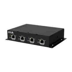
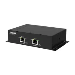
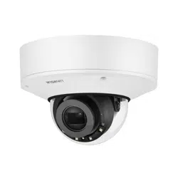
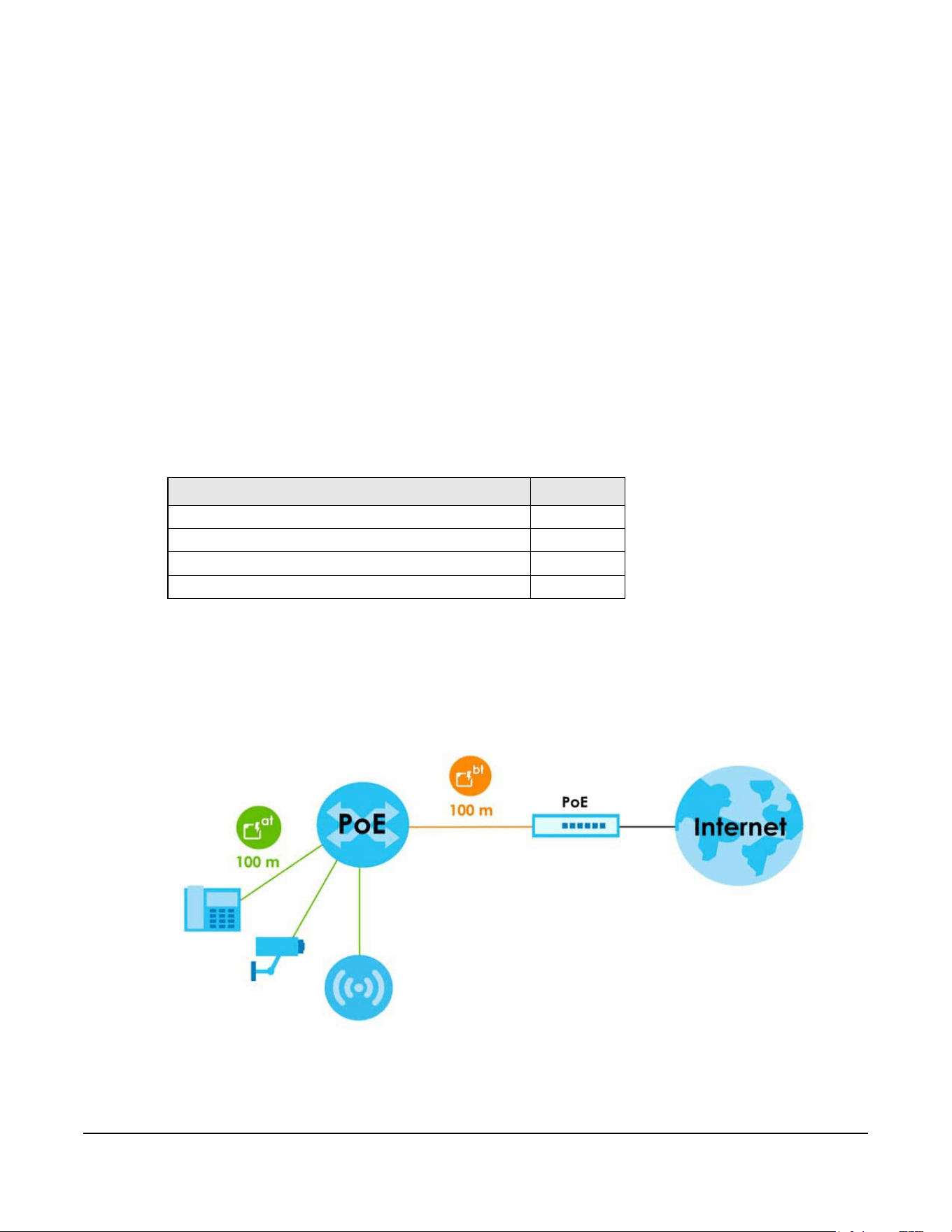
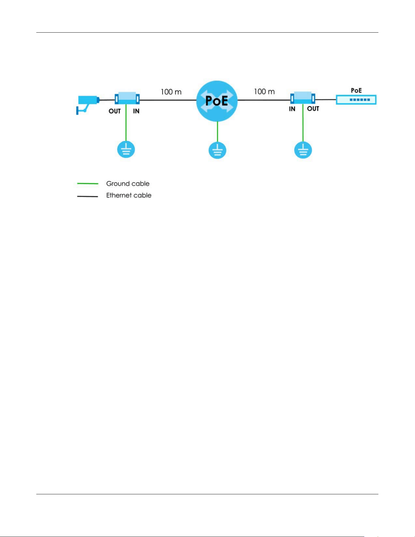
19.1.1 Power over Ethernet (PoE) Example Application
The following example figure shows a PoE12-3PD supplying IEEE 802.3at PoE power and Internet traffic to
PDs such as an AP, an IP camera, or an IP phone.
Figure 13 PoE Example Application
Table 58 Hardware Features
FEATURES POE12-3PD
Number of 10 Mbps/100 Mbps/1 Gbps PoE ports 4
Reset button Yes
Wall mounting Yes
Pole mounting Yes
Chapter 19 Introduction
PoE12-3PD User’s Guide
2
19.2 Features
The following are the essential features of the PoE12-3PD.
• Supports IEEE802.3 10Base-T Ethernet, 802.3u 100Base-Tx Ethernet, 802.3ab 1000Base-T Ethernet.
• 10 Mbps/100 Mbps/1 Gbps Ethernet RJ-45 ports.
• The UPLINK port supports IEEE802.3bt PoE standard. The ports 1-3 support IEEE802.3at and 802.3af PoE
standard.
• Supports IEEE802.3x flow control.
• Supports up to 2K MAC addresses.
•
19.2.1 Power over Ethernet (PoE)
The PoE12-3PD provides a source of power through its Ethernet ports. Each device that receives power
through an Ethernet port is a Powered Device (PD). The PoE12-3PD can adjust the power supplied to
each PD according to the PoE standard the PD supports.
The following are the PoE standards for PoE12-3PD:
• IEEE 802.3af Power over Ethernet / PoE
• IEEE 802.3at Power over Ethernet / PoE+
• IEEE 802.3bt Power over Ethernet / PoE++
The following table describes the PoE12-3PD’s PoE information.
Table 59 PoE Standards of PoE12-3PD Ports
PORT PoE STANDARD PoE POWER BUDGET
Port 1/Port 2/Port 3 IEEE 802.3af
IEEE 802.3at
The PoE power budget depends on the PoE standard
the uplink PoE switch or PoE injector supports:
• 802.3af - 7W
• 802.3at - 19W
• 802.3bt - 45W
UPLINK Port IEEE 802.3af
IEEE 802.3at
IEEE 802.3bt
Table 60 PoE Standards
PoE FEATURES PoE PoE+ PoE++
IEEE Standard IEEE 802.3af IEEE 802.3at IEEE 802.3bt
PoE Type Type 1 Type 2 Type 3
PoE12-3PD Port Power
IEEE Power Classification Class 0, 1, 2, 3 Class 4 Class 5, 6
Maximum Power Per Port 15.4W 30W 60W
Port Voltage Range 44-57V 50-57V 50-57V
Cables
Twisted Pairs Used 2-pair 2-pair 4-pair
Supported Ethernet Cables Cat3/24 AWG or better Cat5 or better/24 AWG
or better
Cat5 or better/24 AWG
or better

Chapter 19 Introduction
PoE12-3PD User’s Guide
3
19.3 How to Manage your PoE12-3PD
You can use the following way to manage your PoE12-3PD.
• Nebula Control Center Web Portal: Use the NCC web portal to monitor your PoE12-3PD. You can
register your PoE12-3PD to a site and organization using the NCC web portal. See Section 19.4.1 on
page 5 for more information.
• Nebula Mobile App: Use the Nebula mobile app to monitor your PoE12-3PD. You can register your
PoE12-3PD to a site and organization using the Nebula Mobile app. Download the Nebula Mobile
app at Apple Store or Google Play. See Section 19.4.2 on page 6 for more information.
• ZON Utility: Zyxel One Network (ZON) Utility is a utility tool that assists you to set up and maintain
network devices in a simple and efficient way. You can download the ZON Utility at www.zyxel.com
and install it on your computer (Windows operating system). See Section 19.5 on page 6 for more
information.
• Web Configurator: This is recommended for everyday management of PoE12-3PD using a supported
web browser. See Section 22.1 on page 16 for more information.
19.4 NCC Management
You can manage the PoE12-3PD with the Nebula Control Center (NCC). The NCC is a cloud-based
network management system that allows you to remotely monitor the Zyxel Nebula Security Appliances
(SA), Ethernet Switches (S), PoE12-3PD (PoE) and Access Points (AP).
Table 61 Management Methods
MANAGEMENT METHOD WHEN TO USE IT
Nebula Mobile App Registration, monitoring and basic management
NCC Web Portal Registration, monitoring and basic management
ZON Utility Monitoring and basic management
PoE12-3PD Web Configurator Advanced management
Chapter 19 Introduction
PoE12-3PD User’s Guide
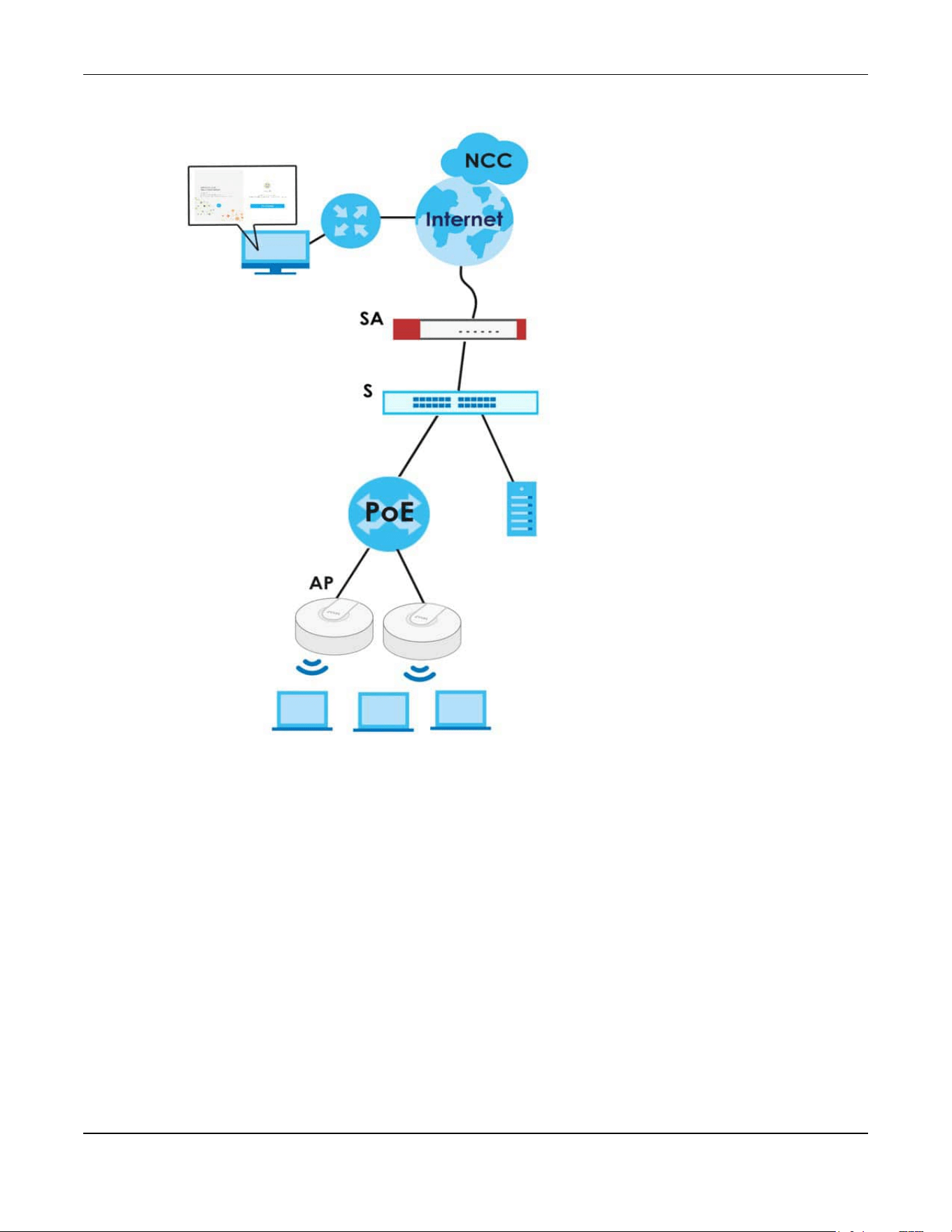
4
Figure 14 NCC Example Network Topology
You need to create a Zyxel Account to log into the NCC first. You can access the NCC through the NCC
web portal through a web browser on your computer or the Nebula Mobile app on your smartphone.
For advanced configurations, use the PoE12-3PD Web Configurator.
See the NCC User’s Guide for how to monitor the PoE12-3PD using Nebula.
Chapter 19 Introduction
PoE12-3PD User’s Guide
5
The PoE12-3PD goes into Cloud mode automatically after it can access
the Nebula web portal and is successfully registered there. Its login
password and settings are then overwritten with what you have
configured in the Nebula web portal. To access the Web Configurator
when the PoE12-3PD is in Cloud mode, use the Local credentials
password to login.
19.4.1 NCC Web Portal
To have NCC monitor the PoE12-3PD, you must first register it at the Nebula web portal at https://
nebula.zyxel.com, and ensure that Nebula Discovery is enabled in Dashboard in the PoE12-3PD Web
Configurator.
From Standalone to NCC Management
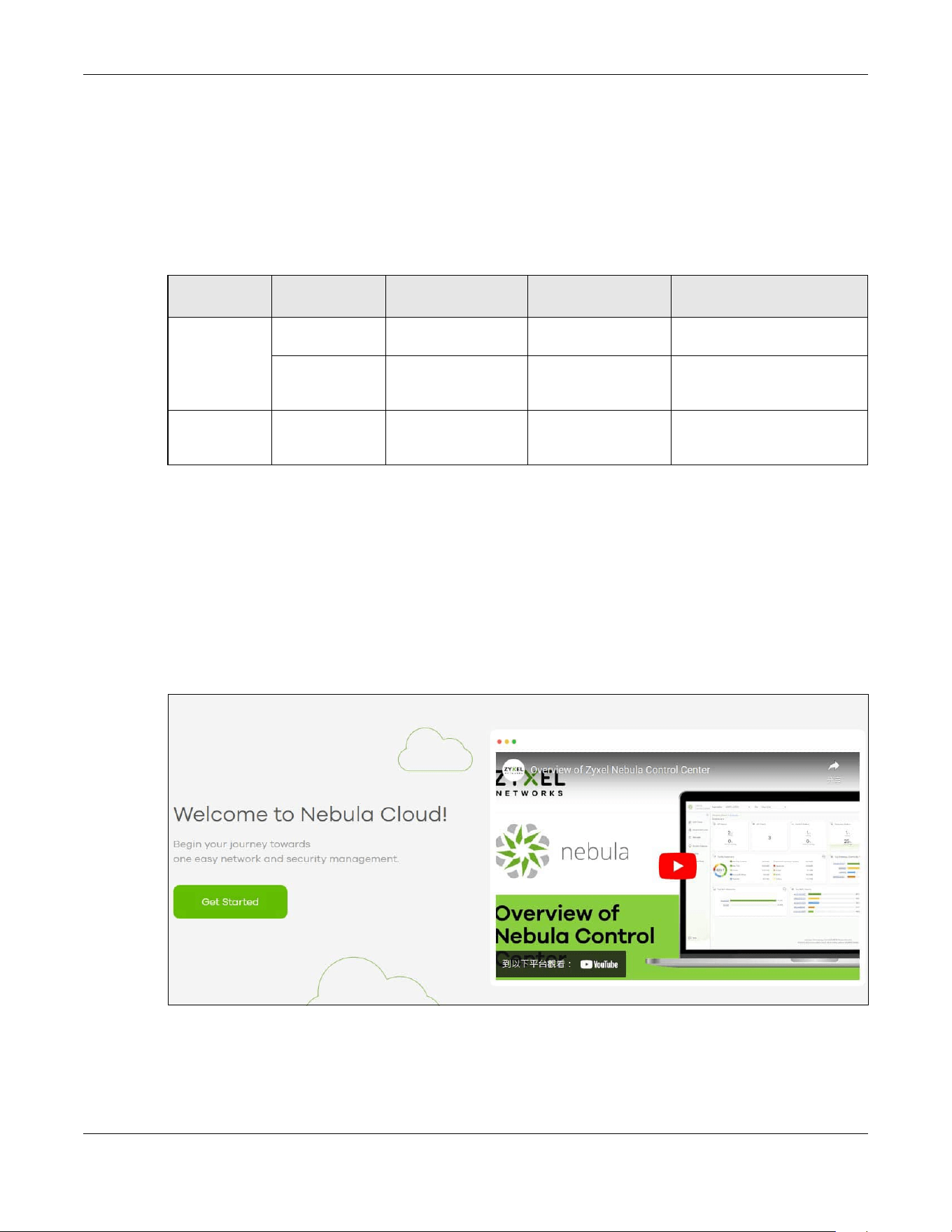
1 Go to https://nebula.zyxel.com. Click Get Started.
2 The login screen displays. Enter your Zyxel Account information to log in. If you do not have one, click
Create account. You will be redirected to another screen where you can sign up for a Zyxel account.
3 Click Create organization to create an organization and a site (using the Nebula setup wizard), or select
an existing site.
Table 62 Management Method Comparison
MODE ACCESS LOGIN USER NAME LOGIN PASSWORD
LOGIN IP ADDRESS/URL/
DOMAIN NAME
Cloud mode NCC Portal Zyxel Account email Zyxel Account
password
https://nebula.zyxel.com
Web
Configurator
(Local GUI)
admin Local credentials
password
https://DHCP-assigned IP
OR
a configured static IP address
Standalone
mode
Web
Configurator
admin 1234 https://DHCP-assigned IP
OR
https://192.168.1.1
Chapter 19 Introduction
PoE12-3PD User’s Guide
6
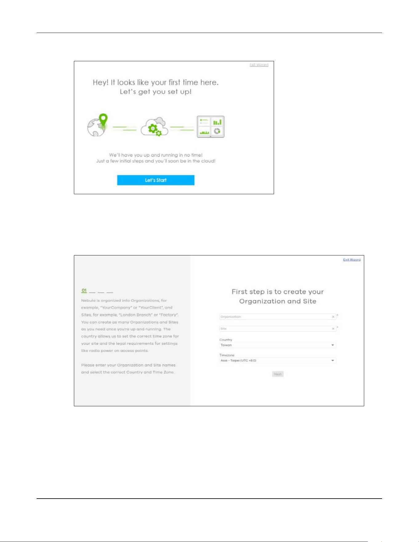
4 If you are creating the first organization under your account, click Let’s Start to begin.
5 Enter a descriptive name for your organization and site. Both names must consist of 1 to 64 characters.
6 Select the time zone of your location. This will set the time difference between your time zone and
Coordinated Universal Time (UTC).
7 Click Next to continue.
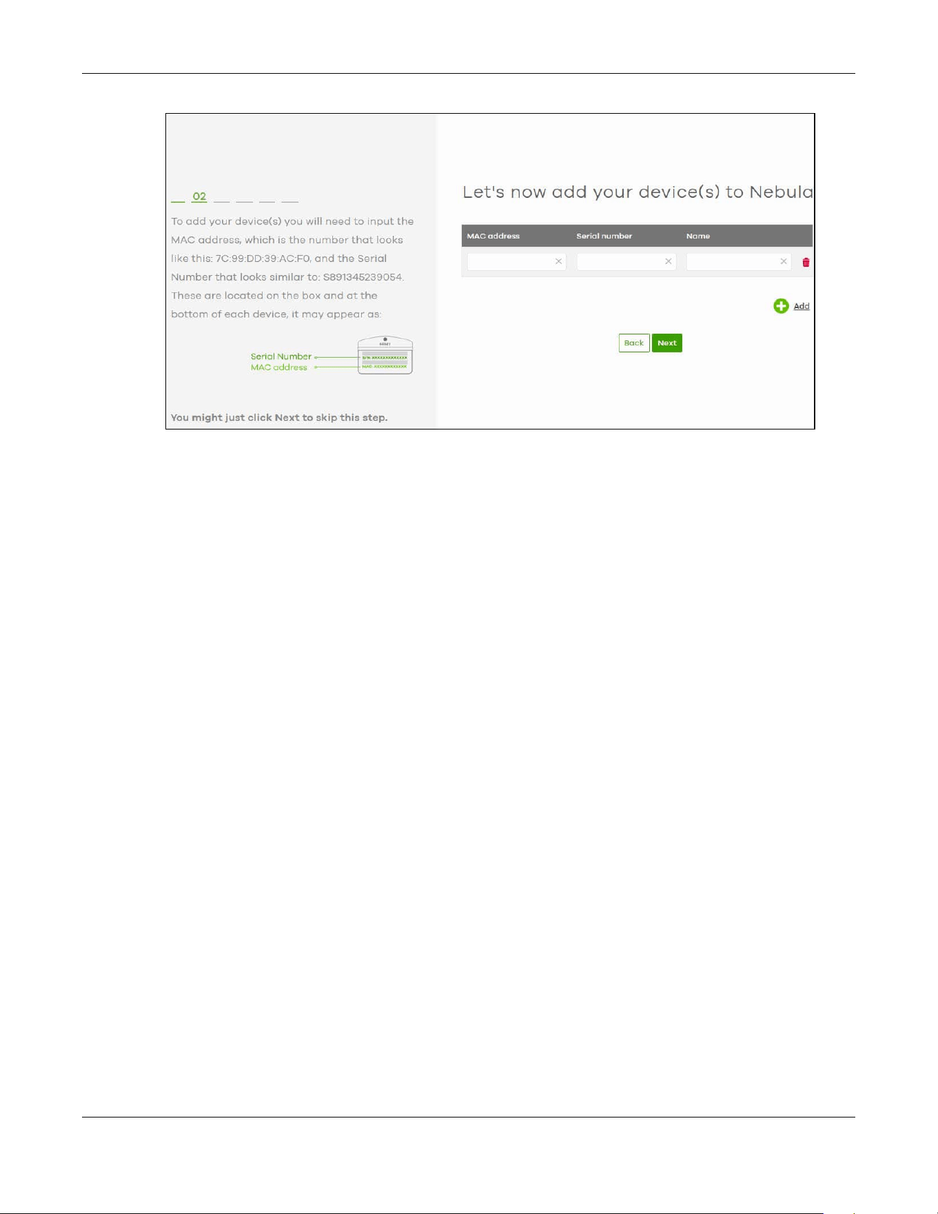
8 Enter your PoE12-3PD MAC address and serial number. Enter a descriptive name for your PoE12-3PD.
9 Click the +Add button to register and add the PoE12-3PD to the site. You can register multiple PoE12-3PD
at a time.
Chapter 19 Introduction
PoE12-3PD User’s Guide
7
10 Click Next to proceed to setting up your WiFi network and guest WiFi network.
Note: Your default web configurator login password will be changed when you register your
PoE12-3PD at NCC. Make sure to check the changed password and change it to your
preferred one before logging in the web configurator. The password must be at least 4
characters long, including one letter and one number. [ ? ], [ | ], [ ' ], [ " ], [ , ] or [ space
] are not allowed.
From NCC Management to Standalone
To return to direct management standalone mode, remove (unregister) the PoE12-3PD from the
inventory in the Nebula web portal.
Note: When you change the PoE12-3PD’s management mode from Cloud mode to
standalone mode, the PoE12-3PD will restore its factory-default settings.
To unregister the PoE12-3PD:
1 Go to the Nebula Control Center (https://nebula.zyxel.com).
2 Go to the Organization-wide > License & inventory > Devices screen.
3 Select the PoE12-3PD you want to remove (unregister) from the organization.
4 Click Actions, then click Remove from organization.
19.4.2 Nebula Mobile App
1 Download and open the Zyxel Nebula Mobile app in your mobile device. Click Start on the first page.
Click Create account to create a Zyxel Account or enter your existing account information to log in.
2 Create an organization and site, or select an existing site using the Zyxel Nebula Mobile app.

Chapter 19 Introduction
PoE12-3PD User’s Guide
8
3 Select a site and scan the PoE12-3PD QR code or manually enter the information to add it to the site.
You can find the QR code:
• On the device label
• On the box
• In the Web Configurator at Dashboard
See Section 20.5 on page 12 for more information about the Cloud mode LED or Section 22.1 on page
16 for more information about the Management Mode field in the Dashboard screen to see if the PoE12-
3PD goes into the Cloud mode successfully.
19.5 ZON Utility
ZON Utility (Zyxel One Network) is a program designed to help you deploy and manage a network more
efficiently. It detects devices automatically and allows you to do basic settings on devices in the
network without having to be near it.
The ZON Utility issues requests via Zyxel Discovery Protocol (ZDP) and in response to the query, the device
responds back with basic information including IP address, firmware version, location, system and model
name in the same broadcast domain. The information is then displayed in the ZON Utility screen and you
can perform tasks like basic configuration of the devices and batch firmware upgrade in it. You can
download the ZON Utility at www.zyxel.com and install it on your computer (Windows operating system).
19.5.1 Requirements
Before installing the ZON Utility on your computer, please make sure it meets the requirements listed
below.
Operating System
At the time of writing, the ZON Utility is compatible with:
• Windows 7 (both 32-bit / 64-bit versions)
• Windows 8 (both 32-bit / 64-bit versions)
• Windows 8.1 (both 32-bit / 64-bit versions)
• Window 10 (both 32-bit / 64-bit versions)
• Window 11 (64-bit version)
Note: To check for your Windows operating system version, right-click on My Computer >
Properties on your computer. You should see this information in the General tab.
Note: It is suggested that you install Npcap, the packet capture library for Windows operating
systems, and remove WinPcap or any other installed packet capture tools before you
install the ZON utility.
Hardware
Here are the minimum hardware requirements to use the ZON Utility on your computer.
Chapter 19 Introduction
PoE12-3PD User’s Guide
9
• Core i3 processor
•2 GB RAM
• 100 MB free hard disk
• WXGA (Wide XGA 1280x800)
19.5.2 Run the ZON Utility
1 Double-click the ZON Utility to run it.
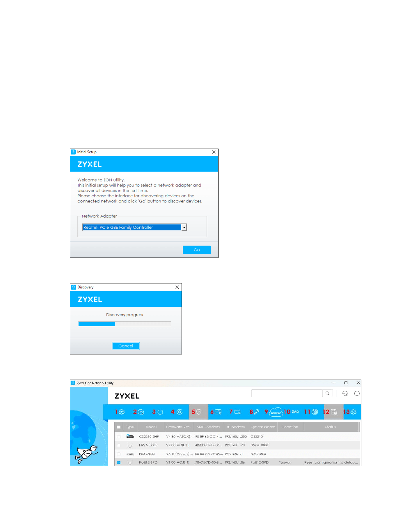
2 Select a network adapter to which your supported devices are connected.
Figure 15 Network Adapter
3 Click the Go button for the ZON Utility to discover all supported devices in your network.
Figure 16 Discovery
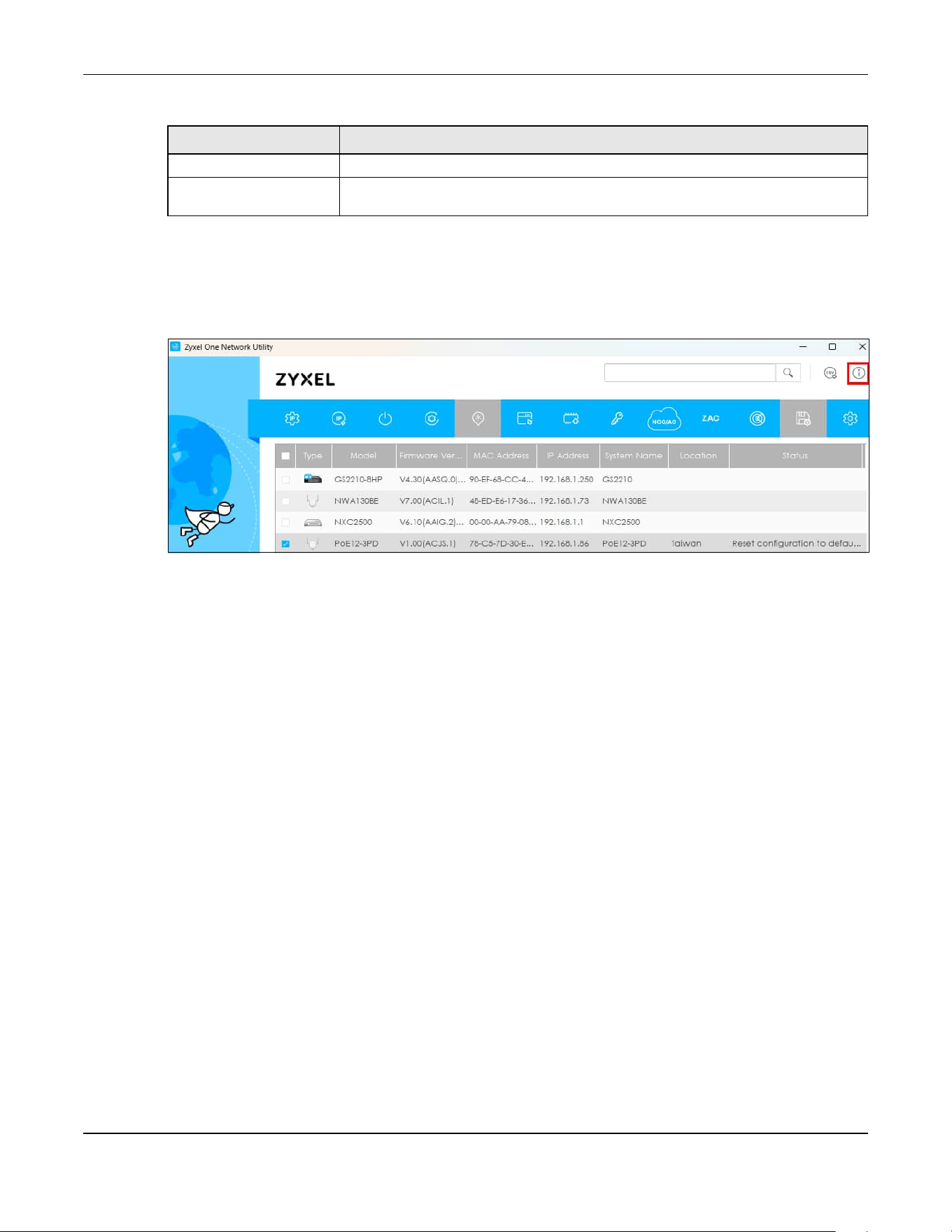
4 The ZON Utility screen shows the devices discovered.
Figure 17 ZON Utility Screen
Chapter 19 Introduction
PoE12-3PD User’s Guide
10
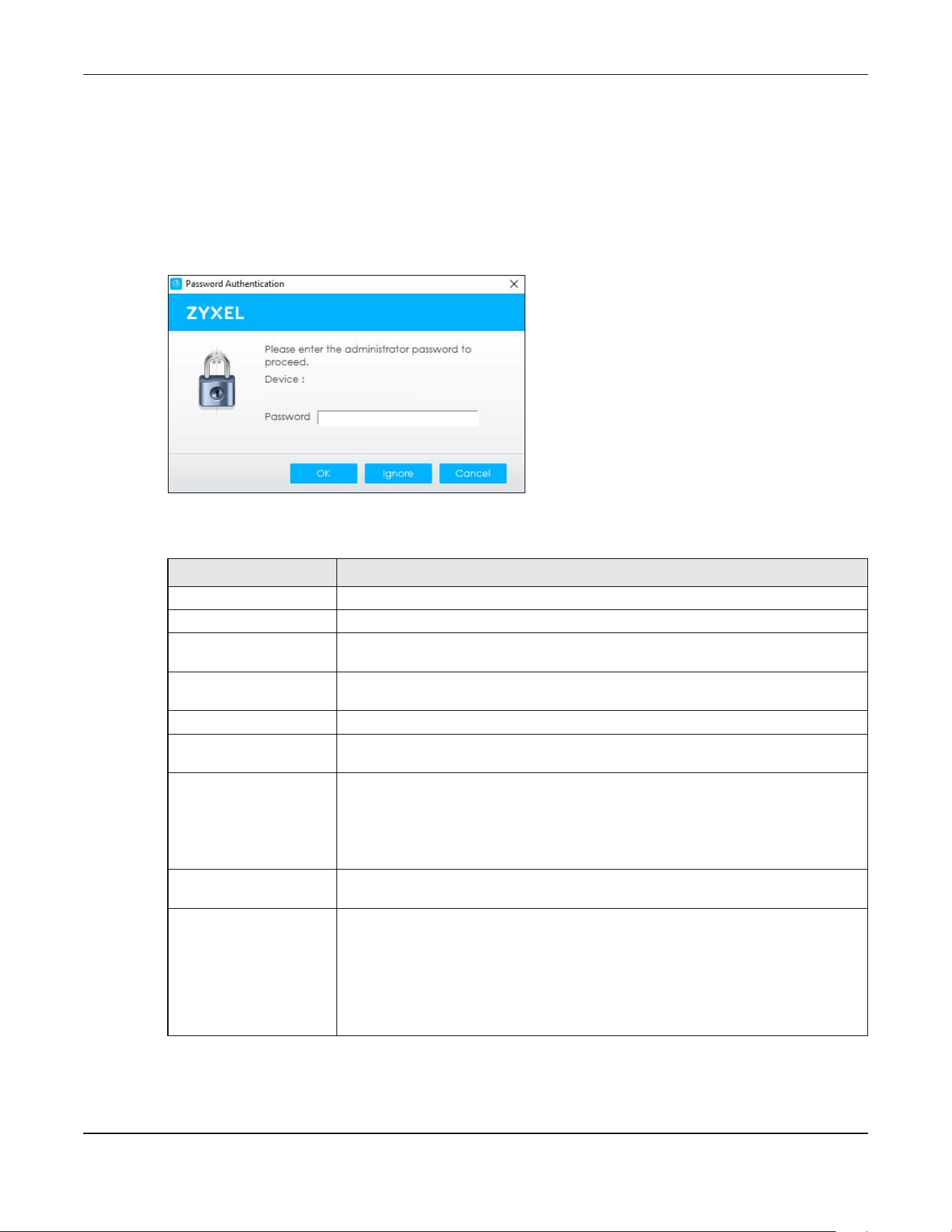
5 Select a device and then use the icons to perform actions. Some functions may not be available for
your devices.
Note: You must know the selected device admin password before taking actions on the
device using the ZON Utility icons. If the selected device is being managed or has been
managed by the NCC, check Local credentials in the NCC's Site-wide > Configure >
Site settings screen for the selected device's current password.
Figure 18 Password Prompt
The following table describes the icons numbered from left to right in the ZON Utility screen.
Table 63 ZON Utility Icons
ICON DESCRIPTION
1 IP Configuration Change the selected device’s IP address.
2 Renew IP Address Update a DHCP-assigned dynamic IP address.
3 Reboot Device Use this icon to restart the selected device(s). This may be useful when troubleshooting
or upgrading new firmware.
4 Reset Configuration to
Default
Use this icon to reload the factory-default configuration file. This means that you will
lose all previous configurations.
5 Locator LED Use this icon to locate the selected device by causing its Locator LED to blink.
6 Web GUI Use this to access the selected device Web Configurator from your browser. You will
need a username and password to log in.
7 Firmware Upgrade Use this icon to upgrade new firmware to selected device(s) of the same model. Make
sure you have downloaded the firmware from the Zyxel website to your computer and
unzipped it in advance.
The ZON only supports a standalone mode AP for the firmware upgrade, it does not
support to upgrade the firmware for a managed mode AP.
8 Change Password Use this icon to change the admin password of the selected device. You must know
the current admin password before changing to a new one.
9 Configure NCC
Discovery
The option is available if the selected device supports Nebula Control Center (NCC)
discovery. You must have Internet access to use this feature. Use this icon on the
selected device to enable or disable the Nebula Control Center (NCC) discovery
feature.
If the feature is enabled, the selected device will try to connect to the NCC. If the
selected device has successfully connected to the NCC and is registered on the NCC,
it will change to the Nebula cloud mode.

Chapter 19 Introduction
PoE12-3PD User’s Guide
11
The following table describes the fields in the ZON Utility main screen.
9 Configure Controller
Discovery and NCC
Discovery
The option is available if the selected device supports AP controller discovery or
Nebula Control Center (NCC) discovery. You must have Internet access to use this
feature. Use this icon on the selected device to enable or disable the:
• AP controller discovery feature
• Nebula Control Center (NCC) discovery feature
If the feature is enabled, the selected device will try to connect to the AP controller/
NCC. If the selected device has successfully connected to an AP controller, it will
change to the AP controller managed mode. If the selected device has successfully
connected to the NCC and is registered on the NCC, it will change to the Nebula
cloud mode.
10 ZAC Use this icon to run the Zyxel AP Configurator of the selected AP.
11 Clear and Rescan Use this icon to clear the list and discover all devices on the connected network again.
12 Save Configuration Use this icon to save configuration changes to permanent memory on a selected
device.
13 Settings Use this icon to select a network adapter for the computer on which the ZON utility is
installed, and the utility language.
Table 64 ZON Utility Fields
LABEL DESCRIPTION
Type This field displays an icon of the kind of device discovered.
Model This field displays the model name of the discovered device.
Firmware Version This field displays the firmware version of the discovered device.
MAC Address This field displays the MAC address of the discovered device.
IP Address This field displays the IP address of an internal interface on the discovered device that
first received an ZDP discovery request from the ZON utility.
System Name This field displays the system name of the discovered device.
Location This field displays where the discovered device is.
Status This field displays whether changes to the discovered device have been done
successfully. As the PoE12-3PD does not support IP Configuration, Renew IP address
and Flash Locator LED, this field displays “Update failed”, “Not support Renew IP
address” and “Not support Flash Locator LED” respectively.
NCC Discovery This field displays if the discovered device supports the Nebula Control Center (NCC)
discovery feature.
If the feature is enabled, the selected device will try to connect to the NCC. If the
selected device has successfully connected to the NCC and is registered on the NCC,
it will change to the Nebula cloud mode.
Controller Discovery This field displays if the discovered device supports the:
• AP controller discovery feature.
• Nebula Control Center (NCC) discovery feature.
If the feature is enabled, the selected device will try to connect to the AP controller/
NCC. If the selected device has successfully connected to an AP controller, it will
change to the AP controller managed mode. If the selected device has successfully
connected to the NCC and is registered on the NCC, it will change to the Nebula
cloud mode.
Serial Number Enter the admin password of the discovered device to display its serial number.
Table 63 ZON Utility Icons (continued)
ICON DESCRIPTION
Chapter 19 Introduction
PoE12-3PD User’s Guide
12
If you want to check the supported models and firmware versions later, you can click the Show
information about ZON icon in the upper right hand corner of the screen. Then select the Supported
model and firmware version link. If your device is not listed here, see the device release notes for ZON
Utility support. The release notes are in the firmware zip file on the Zyxel web site.
Figure 19 ZON Utility Screen
19.6 Good Habits for Managing the PoE12-3PD
Do the following things regularly to make the PoE12-3PD more secure and to manage the PoE12-3PD
more effectively.
• Change the password. Use a password that is not easy to guess and that consists of different types of
characters, such as numbers and letters.
Hardware Version This field displays the hardware version of the discovered device.
IPv6 Address This field displays the IPv6 address of an internal interface on the discovered device
that first received an ZDP discovery request from the ZON utility.
Table 64 ZON Utility Fields (continued)
LABEL DESCRIPTION
PoE12-3PD User’s Guide
10
CHAPTER 20
Hardware
The PoE12-3PD has IP55 waterproof and dustproof housing, making it suitable for outdoor installation. The
PoE12-3PD’s Ethernet ports have 6kV surge protection.
You can manage and monitor the connected Power Devices using Nebula. If errors occur, reboot the
connected Power Devices using Nebula. See Section 19.4 on page 3 for more information.
This chapter describes the ports of the PoE12-3PD and shows you how to make the hardware
connections.
See the Quick Start Guide for how to do the hardware installation, mounting, and Internet setup.
20.1 Port Connections
The following figures show the ports of the PoE12-3PD.
Figure 15 PoE12-3PD Ports

Chapter 20 Hardware
PoE12-3PD User’s Guide
11
The following table describes the ports.
20.2 Grounding and Surge Protection
The PoE12-3PD is an outdoor device with built-in surge protection. However, it must be properly
grounded.
Grounding is a safety measure to direct excess electric charge to the ground. It prevents damage to
the PoE12-3PD, and protects you from electrocution. Any device that is located outdoors and
connected to this product must be properly grounded and surge protected. To the extent permissible
by your country’s applicable law, failure to follow these guidelines could result in damage to your PoE12-
3PD which may not be covered by its warranty.
Note: Qualified service personnel must ensure the building’s protective earthing terminals are
valid terminals.
Note: Note: The protective earthing conductor must be installed by a technician.
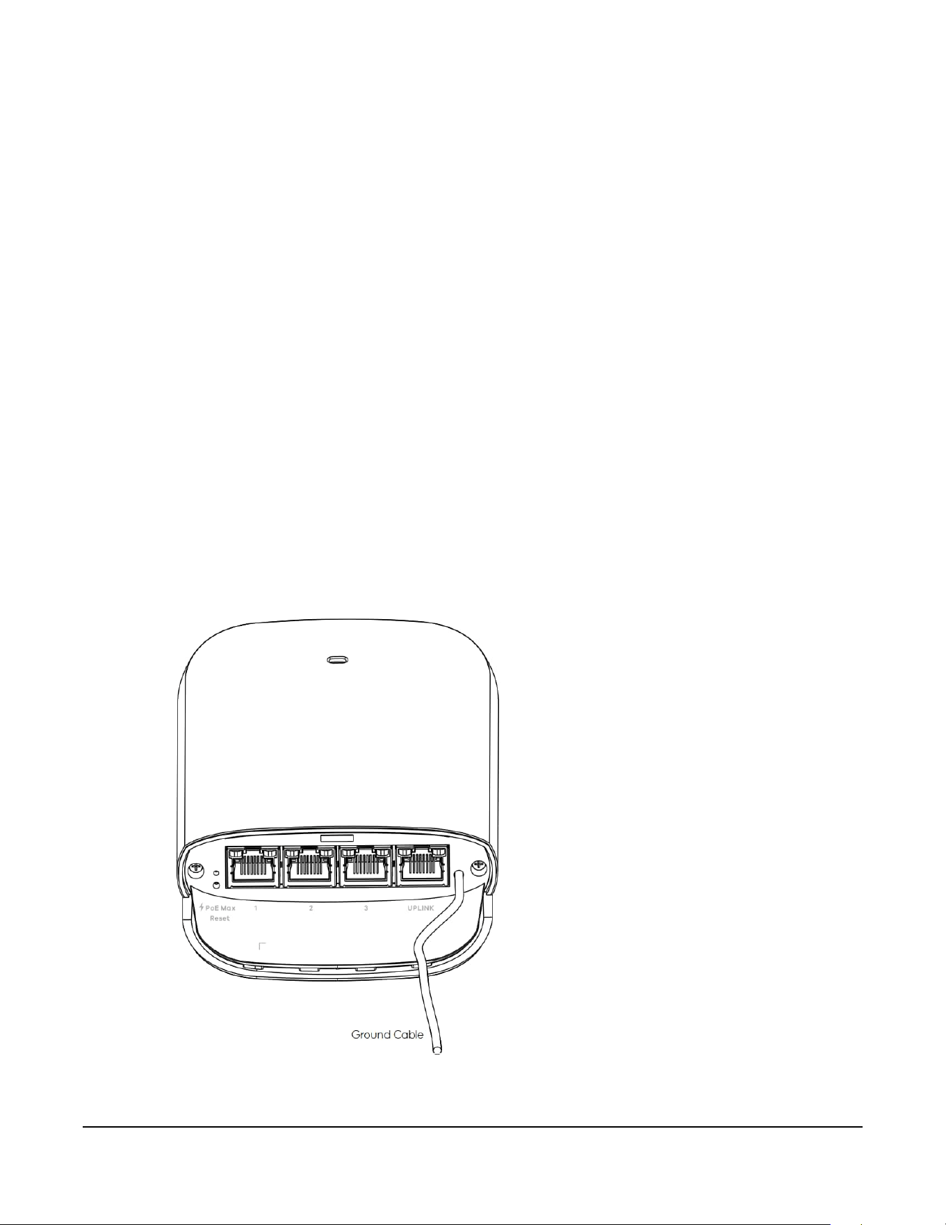
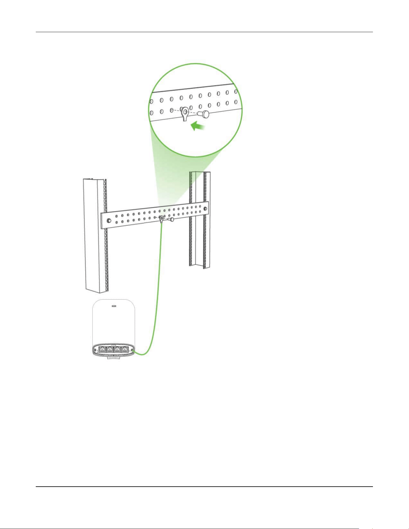
20.2.1 Grounding
1 Push down and slide out the device cover.
2 To help protect against lightning and electromagnetic interference, connect the green/yellow ground
cable to a grounding bar or on-site grounding terminal.
Table 65 Port Connections
LABEL DESCRIPTION
Port 1 / Port 2 / Port 3 Connect the ports to an Ethernet device, such as a PoE AP, IP camera or IP phone.
UPLINK Connect the port to a PoE switch or PoE injector with power source.
Chapter 20 Hardware
PoE12-3PD User’s Guide
12
Figure 16 PoE12-3PD Grounding
This device must be grounded. Do this before you make other
connections.
20.2.2 Surge Protection
For the PoE switch/PoE injector or PDs that connected to the PoE12-3PD that lack surge protection, it is
recommended to add a surge protector between the PoE12-3PD and the device that needs
protection.
In the following figure, the PoE switch and the IP camera lack surge protection. A surge protector is
installed between the PoE switch and the PoE12-3PD, placed closer to the PoE switch to protect it.
Chapter 20 Hardware
PoE12-3PD User’s Guide
13
Another surge protector is installed between the IP camera and the PoE12-3PD, placing closer to the IP
camera to protect it.
Figure 17 PoE12-3PD Surge Protection Example
20.3 Power Connection
1 Connect the UPLINK port of the PoE12-3PD to a PoE switch or PoE injector that supplies power to the
PoE12-3PD.
2 Connect the compatible Ethernet devices requiring power (Powered Devices) to port 1, 2 or 3 of the
PoE12-3PD.
3 Gently push each connected Ethernet cable into each slot of the PoE12-3PD cover. Be careful not to
damage the cables.
4 Slide the cover back onto the PoE12-3PD until it clicks into place.
20.4 Mounting
The following figure shows the back of the PoE12-3PD. See the Quick Start Guide for how to do the wall
and pole mounting.
Chapter 20 Hardware
PoE12-3PD User’s Guide
14
Figure 18 PoE12-3PD Back
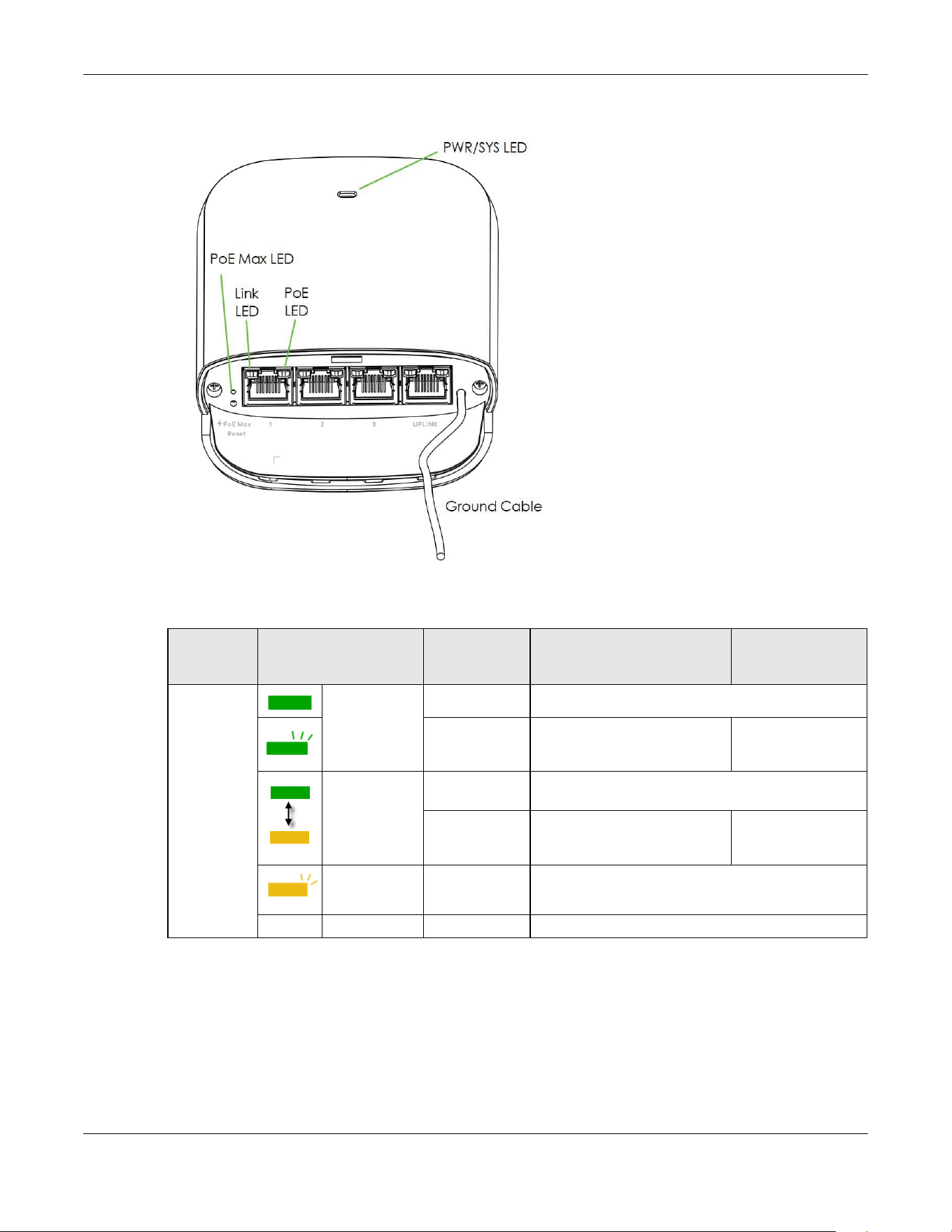
20.5 LEDs
The LED Indicators show the current status of the PoE12-3PD. After powering the PoE12-3PD on, see the
LEDs to ensure the PoE12-3PD is working properly or diagnose any issues.
The PoE MAX LED shows the remaining PoE power available for the Powered Devices (PDs) connected
to ports 1, 2 and 3. The Power MAX LED represents the total power received from the PoE switch or PoE
injector through the UPLINK port minus the total power sent to the PDs on ports 1, 2 and 3. See Table 59
on page 2 to see the PoE standard of each port.
• PoE MAX = Total PoE In (UPLINK port) - Total PoE Out (ports 1, 2, and 3)
Chapter 20 Hardware
PoE12-3PD User’s Guide
15
Figure 19 PoE12-3PD LEDs
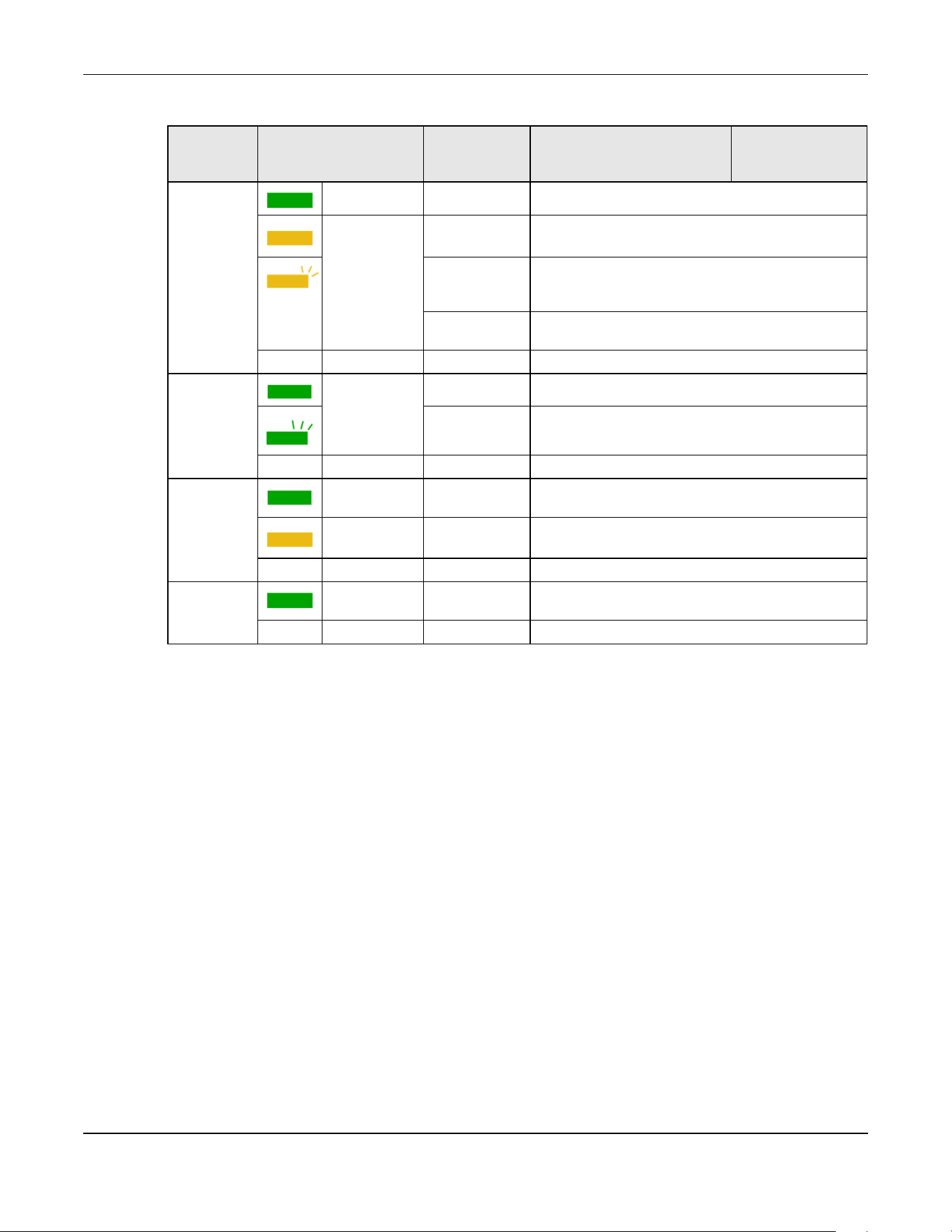
The following table describes the LEDs.
Table 66 LED Descriptions
LED COLOR STATUS CLOUD MODE
STANDALONE
(NCC DISCOVERY
DISABLED)
PWR/SYS Green On The PoE12-3PD is ready to use.
Blinking The PoE12-3PD is connected to
the NCC but has not been
registered with it.
N/A
Yellow - Green Fast Blinking
(300ms interval)
The PoE12-3PD is booting.
Slow Blinking
(1-second
interval)
The PoE12-3PD is trying to
connect to the NCC, but the
Internet is down.
N/A
Yellow Blinking The PoE12-3PD is undergoing firmware upgrade.
Off The power is off.
Chapter 20 Hardware
PoE12-3PD User’s Guide
16
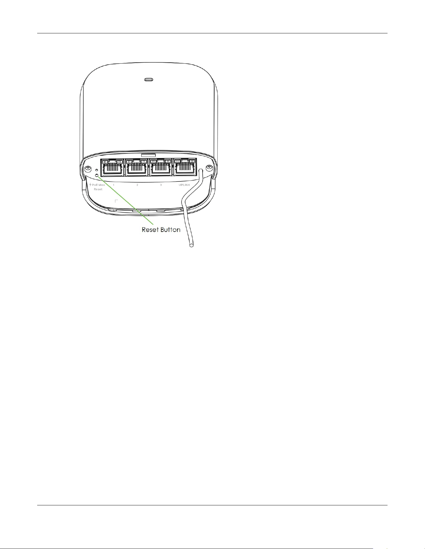
20.6 Reset Button
If you forget your password or you cannot access the Web Configurator, you will need to use the Reset
button of the PoE12-3PD to reload the factory-default configuration file. This means that you will lose all
configurations that you had previously saved, the password will be reset to 1234.
1 Make sure the power LED is on (not blinking).
2 Use a pin to press the Reset button for longer than 5 seconds to set the PoE12-3PD back to its factory-
default configurations.
PoE MAX Green On The remaining power budget is more than 30 Watts.
Yellow On The remaining power budget is between 15.4 and 30
Watts.
Slow Blinking
(1-second
interval)
The remaining power budget is between 7 and 15.4
Watts.
Fast Blinking
(300ms interval)
The remaining power budget is between 3.84 and 7
Watts.
Off The remaining power budget is less than 3.84 Watts.
Link/ACT (
left of the
ports)
Green On The 10/100/1000 Mbps connection is ready.
Blinking The port is transmitting data at 10/100/1000 Mbps.
Off No connection or the port is shut down.
PoE (right of
the UPLINK
port)
Green On The port's receiving PoE power is up to 51 Watts (IEEE
802.3bt).
Yellow On The port's receiving PoE power is up to 25.5 /12.95
Watts (IEEE 802.3at/af).
Off No PoE power is provided.
PoE (right of
ports1-3)
Green On The supplying PoE power of the port is up to 30 /15.4
Watts (IEEE 802.3at/af).
Off No PoE power is provided.
Table 66 LED Descriptions (continued)
LED COLOR STATUS CLOUD MODE
STANDALONE
(NCC DISCOVERY
DISABLED)
Chapter 20 Hardware
PoE12-3PD User’s Guide
17
Figure 20 Reset Button of the PoE12-3PD

28
PART II
Technical Reference
PoE12-3PD User’s Guide
14
CHAPTER 21
Web Configurator
21.1 Overview
This chapter introduces the configuration and functions of the Web Configurator.
The Web Configurator is an HTML-based management interface that allows easy system setup and
management through Internet browser. Use a browser that supports HTML5, such as Microsoft Edge,
Mozilla Firefox, or Google Chrome. The recommended minimum screen resolution is 1024 by 768 pixels.
In order to use the Web Configurator you need to allow:
• Web browser pop-up windows from your device.
• JavaScript (enabled by default).
• Java permissions (enabled by default).
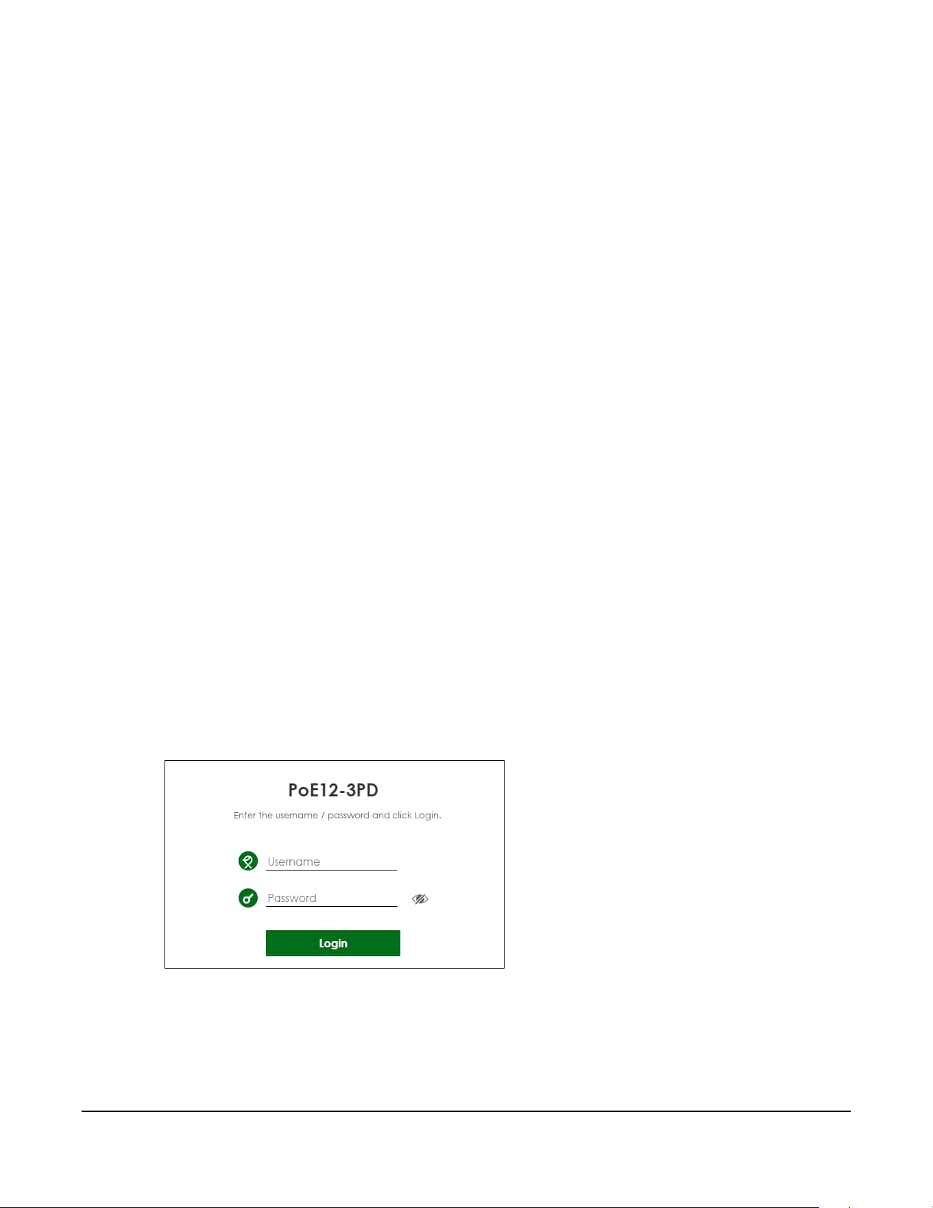
21.2 System Login
1 Make sure your PoE12-3PD hardware is properly connected, and your computer is connected to the
PoE12-3PD through a wired connection. See the Quick Start Guide.
2 Enter the PoE12-3PD’s DHCP-assigned IP address or https://192.168.1.1 in the browser. If your PoE12-3PD is
in cloud mode, check the NCC’s Site-wide > Devices > Accessories screen for the PoE12-3PD’s LAN IP
address.
Figure 16 Login Page: Standalone Mode
Chapter 21 Web Configurator
PoE12-3PD User’s Guide
15
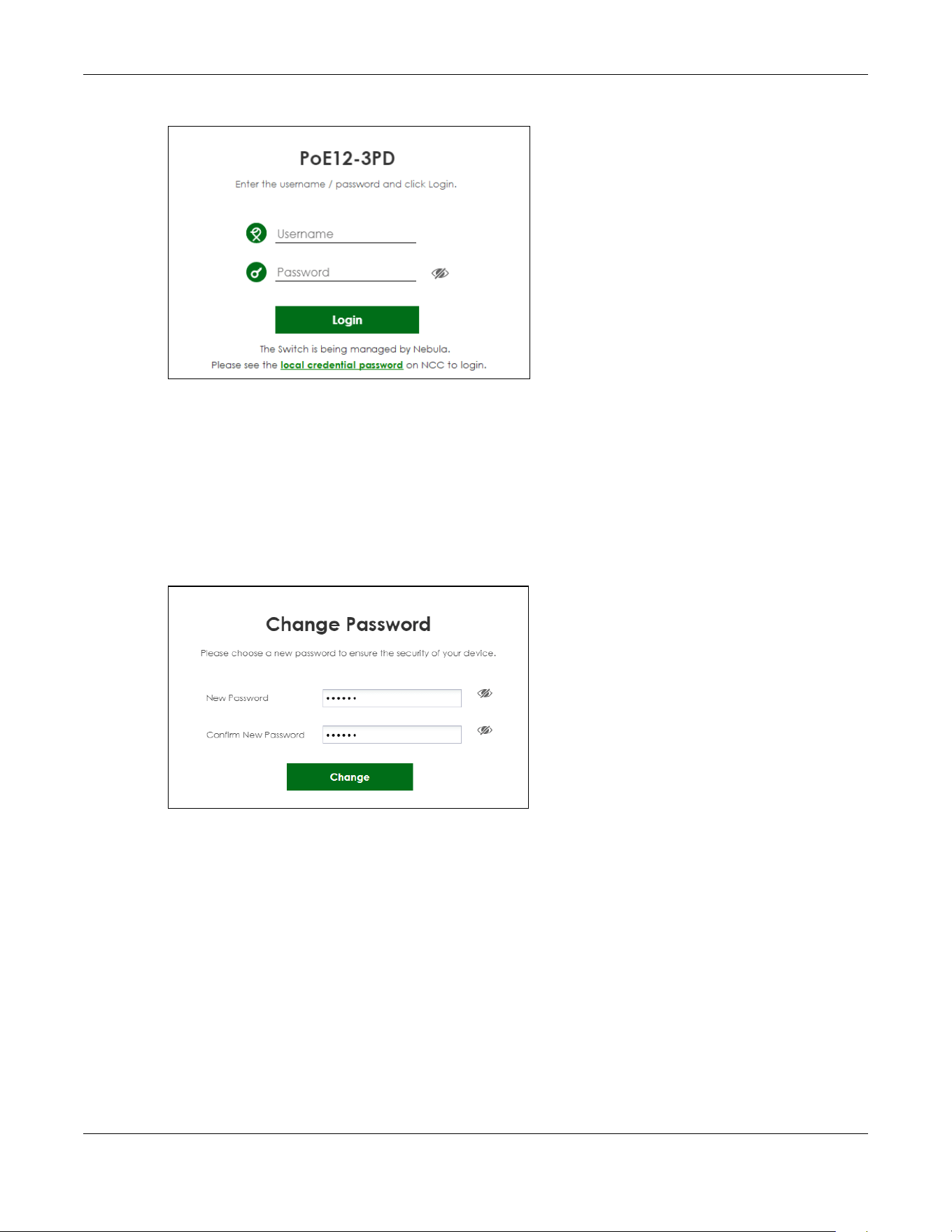
Figure 17 Login Page: Cloud Mode
3 Enter the user name (default: admin) and password (default: 1234). Click Login.
If your PoE12-3PD is being managed or has been managed by the NCC, check Local credentials
password in the NCC's Site-wide > Configure > Site settings screen for the PoE12-3PD's current password.
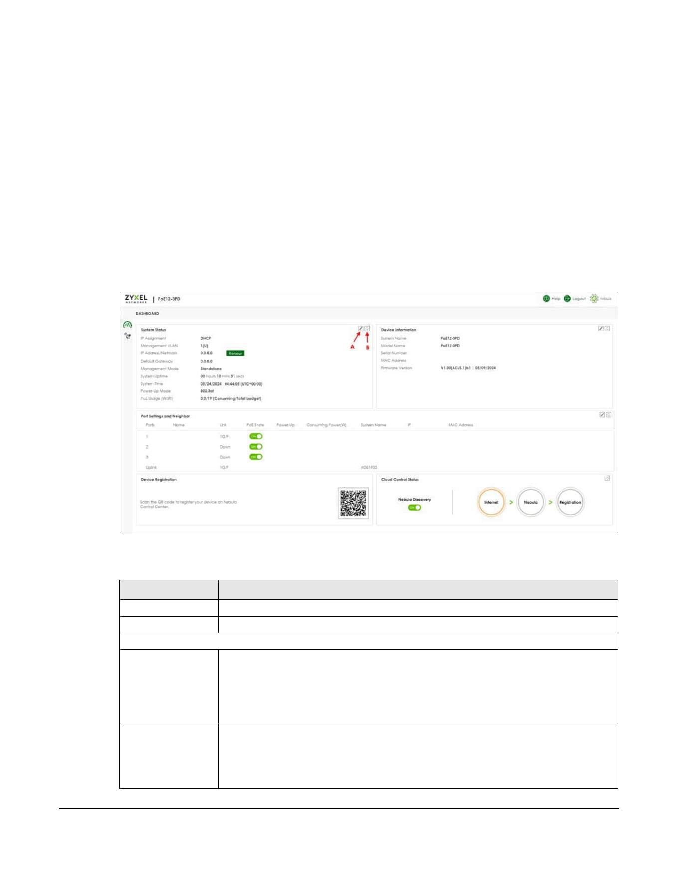
4 The following screen displays if you log into the PoE12-3PD for the first time. Enter a new password using
the keyboard characters (except [ ? ], [ | ], [ ' ], [ " ], [ , ] or [ space ]). The password must be 4 to 63
characters long. Retype it to confirm and click Change to go to the login page and log in with your new
password.
Figure 18 Login Page: Password Change
PoE12-3PD User’s Guide
16
CHAPTER 22
Dashboard
22.1 Dashboard
The Dashboard screen displays when you log into the PoE12-3PD or click the icon at the top left of the
Web Configurator. The Dashboard screen displays general device information, port status, system
information, and NCC status.
Figure 16 Dashboard
The following table describes the labels in this screen.
Table 67 Dashboard
LABEL DESCRIPTION
Edit (A) Click this to edit the settings. See Section 22.2 on page 18 for more information.
Refresh (B) Click this to update the widget’s information immediately.
System Status
IP Assignment This field displays how the PoE12-3PD gets its IP address.
Static - The PoE12-3PD has a static IP address.
DHCP - The PoE12-3PD gets its IP address from a DHCP server.
Click the Renew button to update the DHCP IP address.
Management VLAN This field displays:
• The VLAN the PoE12-3PD used to manage network. By default, the management VLAN
is 1.
• Whether a port is participating in a VLAN. A port’s tagged VLAN ID is displayed after T. A
port’s untagged VLAN ID is displayed after U.

Chapter 22 Dashboard
PoE12-3PD User’s Guide
17
IP Address The PoE12-3PD needs an IP address for it to be managed over the network. The factory
default IP address is 192.168.1.1.
This field displays the PoE12-3PD’s current IP address.
Default Gateway The field displays the gateway that allows you to send or receive data traffic to or from a
different network than the one the PoE12-3PD is on.
Management Mode This field displays whether the PoE12-3PD is being managed by NCC.
• Standalone: When working in standalone mode, the PoE12-3PD is configured mainly
with its built-in Web Configurator. The PoE12-3PD is in standalone mode by default.
• Cloud: You can manage and monitor the PoE12-3PD through the NCC. It offers many
features to better manage and monitor not just the Zyxel Device, but your network as a
whole. See Section 19.4 on page 3 on how to switch your PoE12-3PD to Cloud mode.
System Uptime This field displays how long the PoE12-3PD has been running since it last restarted or was
turned on.
System Time This field displays the current date and time. The format is mm/dd/yyyy hh:mm:ss (UTC +
hh:mm).
Power-Up Mode This field displays the IEEE PoE standard of the power received from the UPLINK port. This
affects the available PoE usage for PDs. See Table 59 on page 2 to see more information on
PoE standard of the ports.
PoE Usage (Watt) This field displays the amount of power the PoE12-3PD is currently supplying to the
connected PoE-enabled devices and the total power the PoE12-3PD can provide to the
connected PDs.
Device Information
System Name This field displays the name used to identify the PoE12-3PD on the network.
Model Name This field displays the model name of the PoE12-3PD.
Serial Number This field displays the serial number of the PoE12-3PD.
MAC Address This field displays the MAC address of the PoE12-3PD.
Firmware Version This field displays the version number and date of the firmware the PoE12-3PD is currently
running.
Port Settings and Neighbor
Ports This identifies the Ethernet port on the PoE12-3PD.
Name This field displays the name you assigned to this port.
Link This field displays the current link speed (either 10M for 10 Mbps, 100M for 100 Mbps, or 1G
for 1 Gbps) and duplex mode (F for full duplex or H for half) for each connected port. It
displays Down for non-connected ports.
PoE State Slide the switch to the right to enable supplying PoE power to the PD.
Power-Up This field displays the IEEE PoE standard of the supplying power of each port.
Consuming Power
(W)
This field displays the amount of power the PoE12-3PD is currently supplying to the
connected PDs.
System Name This field displays the system name of the connected device.
IP This field displays the IP address of the connected device
MAC Address This field displays the MAC address of the connected device.
Device Registration Scan the QR code to go to the Nebula Mobile app and register your PoE12-3PD with NCC.
Table 67 Dashboard (continued)
LABEL DESCRIPTION

Chapter 22 Dashboard
PoE12-3PD User’s Guide
18
22.2 Edit Dashboard
This section describes how to configure the settings in the Dashboard screen.
22.2.1 Network
To access this screen, click the Edit icon under the System Status section.
Cloud Control Status This field displays:
• The PoE12-3PD Internet connection status.
• The connection status between the PoE12-3PD and NCC.
• The PoE12-3PD registration status on NCC.
Mouse over the circles to display detailed information.
To pass your PoE12-3PD management to NCC, first make sure your PoE12-3PD is connected
to the Internet. Then go to NCC and register your PoE12-3PD.
Note: All circles will gray out if you disable Nebula Discovery.
1. Internet
Green - The PoE12-3PD is connected to the Internet.
Orange - The PoE12-3PD is not connected to the Internet.
2. Nebula
Green - The PoE12-3PD is connected to NCC.
Orange - The PoE12-3PD is not connected to NCC.
3. Registration
Green - The PoE12-3PD is registered on NCC.
Gray - The PoE12-3PD is not registered on NCC.
Nebula Discovery Slide the switch to the right to enable NCC discovery on the PoE12-3PD. The PoE12-3PD will
connect to NCC and change to the NCC management mode if it:
• is connected to the Internet.
• has been registered on NCC.
Table 67 Dashboard (continued)
LABEL DESCRIPTION
PoE12-3PD User’s Guide
19
Figure 17 Dashboard > Edit System Status
The following table describes the labels in this screen.
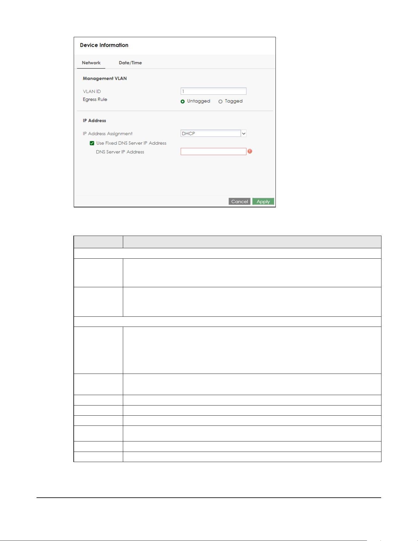
Table 68 Dashboard > Edit System Status > Network
LABEL DESCRIPTION
Management VLAN
VLAN ID Enter a VLAN ID between 1 and 4090 for your PoE12-3PD to join. The default VLAN ID is 1.
Your PC needs to be in the same VLAN group as the PoE12-3PD in order to access the Web
Configurator.
Egress Rule Select to tag or untag outgoing data for the management VLAN.
•Untagged
•Tagged
IP Address
IP Address
Assignment
Select how the PoE12-3PD gets its IP address.
DHCP - Select this if there is a DHCP server that can assign the PoE12-3PD an IP address, subnet
mask, a default gateway IP address and a domain name server IP address automatically.
Static - Select this if you do not have a DHCP server or if you wish to assign static IP address
information to the PoE12-3PD. You need to fill in the following fields when you select this option.
Use Fixed
DNS Server IP
Address
Select this to specify an IP address for the Domain Name System (DNS) Server.
IP Address Enter the IP address of your PoE12-3PD in dotted decimal notation.
Subnet Mask Enter the IP subnet mask in dotted decimal notation, for example, 255.255.255.0.
Gateway Enter the default gateway of the PoE12-3PD.
DNS Server IP
Address
Enter a specific IP address for the DNS Server.
Cancel Click this to reset the fields to the previous configuration.
Apply Click this to save your changes to the PoE12-3PD.
Chapter 22 Dashboard
PoE12-3PD User’s Guide
20
22.2.2 Date/Time
For effective scheduling and logging, the PoE12-3PD system time must be accurate. The PoE12-3PD has
a software mechanism to set the time manually or get the current time and date from an external
server.
To access this screen, click the Edit icon under the System Status section and click Date/Time.
Figure 18 Dashboard > Edit System Status > Date/Time
The following table describes the labels in this screen.
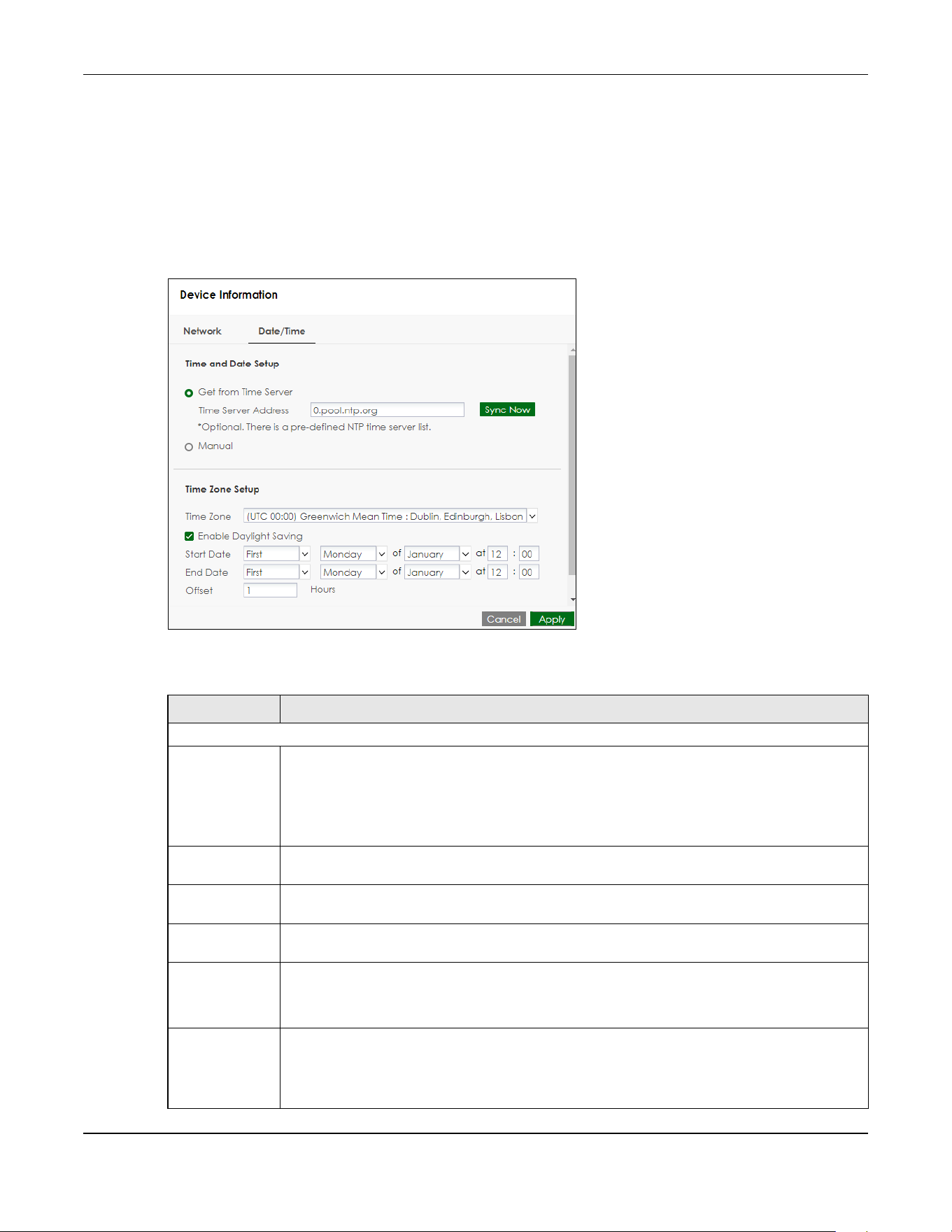
Table 69 Dashboard > Edit System Status > Date/Time
LABEL DESCRIPTION
Time and Date Setup
Get from time
server
Select this to have the PoE12-3PD get the time from the time server. The PoE12-3PD requests time
and date settings from the time server under the following circumstances.
• When the PoE12-3PD starts up.
• When you click Apply after selecting Get from time server in this screen.
• 24-hour intervals after starting up.
Time Server
Address
Enter the IP address or URL of your time server. Check with your ISP/network administrator if you
are unsure of this information.
Sync Now Click this button to have the PoE12-3PD get the time and date from a time server (see the Time
Server Address field). This also saves your changes (except the daylight saving settings).
Manual Select this to enter or select the time and date manually. When you enter the time and date
settings manually, the PoE12-3PD uses the new settings once you click Apply.
New Time
(hh:mm:ss)
This field displays the last updated time from the time server or the last time configured manually.
When you set Time and Date Setup to Manual, enter the new time in this field and then click
Apply.
New Date
(yyyy-mm-
dd)
This field displays the last updated date from the time server or the last date configured
manually.
When you set Time and Date Setup to Manual, enter the new date in this field and then click
Apply.

Chapter 22 Dashboard
PoE12-3PD User’s Guide
21
Pre-defined NTP Time Servers List
When you turn on the PoE12-3PD for the first time, the PoE12-3PD then attempts to synchronize with one
of the following pre-defined list of Network Time Protocol (NTP) time servers in order from the first one until
it is successful.
The PoE12-3PD continues to use the pre-defined list of NTP time servers if you do not specify a time server
or it cannot synchronize with the time server you specified.
Time Zone Setup
Time Zone Choose the timezone of the PoE12-3PD’s location. This will set the time difference between your
timezone and Coordinated Universal Time (UTC).
Enable Daylight
Saving
Daylight savings is a period from late spring to early fall when many countries set their clocks
ahead of normal local time by one hour to give more daytime light in the evening.
Select this option if your country observes Daylight Saving Time.
Start Date Configure the day and time when Daylight Saving Time starts if you selected Enable Daylight
Saving. The at field uses the 24 hour format. Here are a couple of examples:
Daylight Saving Time starts in most parts of the United States on the second Sunday of March.
Each time zone in the United States starts using Daylight Saving Time at 2 A.M. local time. So in
the United States you would select Second, Sunday, March and type 2 in the at field.
Daylight Saving Time starts in the European Union on the last Sunday of March. All of the time
zones in the European Union start using Daylight Saving Time at the same moment (1 A.M. UTC).
So in the European Union you would select Last, Sunday, March. The time you type in the at field
depends on your time zone. In Germany for instance, you would type 2 because Germany's
time zone is one hour ahead of UTC (UTC+1).
End Date Configure the day and time when Daylight Saving Time ends if you selected Enable Daylight
Saving. The at field uses the 24 hour format. Here are a couple of examples:
Daylight Saving Time ends in the United States on the first Sunday of November. Each time zone
in the United States stops using Daylight Saving Time at 2 A.M. local time. So in the United States
you would select First, Sunday, November and type 2 in the at field.
Daylight Saving Time ends in the European Union on the last Sunday of October. All of the time
zones in the European Union stop using Daylight Saving Time at the same moment (1 A.M. UTC).
So in the European Union you would select Last, Sunday, October. The time you type in the at
field depends on your time zone. In Germany for instance, you would type 2 because
Germany's time zone is one hour ahead of UTC (UTC+1).
Offset Specify how much the clock changes when daylight saving begins and ends.
Enter a number from 1 to 5.5 (by 0.5 increments).
For example, if you set this field to 3.5, a log occurred at 6 P.M. in local official time will appear as
if it had occurred at 9:30 P.M.
Cancel Click this to reset the fields to the previous configuration.
Apply Click this to save your changes to the PoE12-3PD.
Table 70 Default Time Servers
time.windows.com
time.apple.com
time.cloudflare.com
Table 69 Dashboard > Edit System Status > Date/Time (continued)
LABEL DESCRIPTION
Chapter 22 Dashboard
PoE12-3PD User’s Guide
22
22.2.3 Device Setting
To access this screen, click the Edit icon under the Device Information section.
Figure 19 Dashboard > Edit Device Information
The following table describes the labels in this screen.
22.2.4 Port Settings
To access this screen, click the Edit icon under the Port Settings and Neighbor section.
Figure 20 Dashboard > Edit Port Settings and Neighbor
The following table describes the labels in this screen.
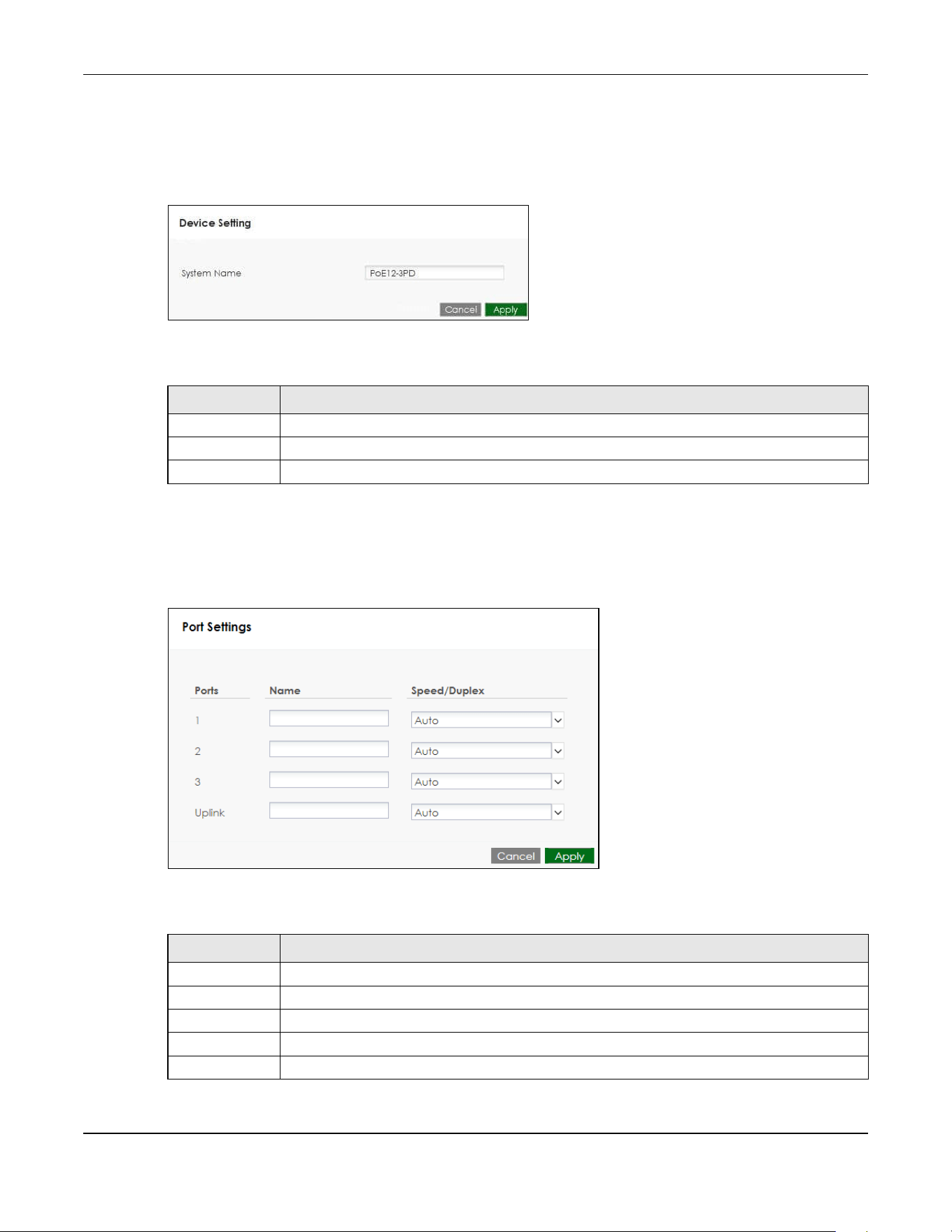
Table 71 Dashboard > Edit Device Information
LABEL DESCRIPTION
System Name Enter a system name for the PoE12-3PD.
Cancel Click this to reset the fields to the previous configuration.
Apply Click this to save your changes to the PoE12-3PD.
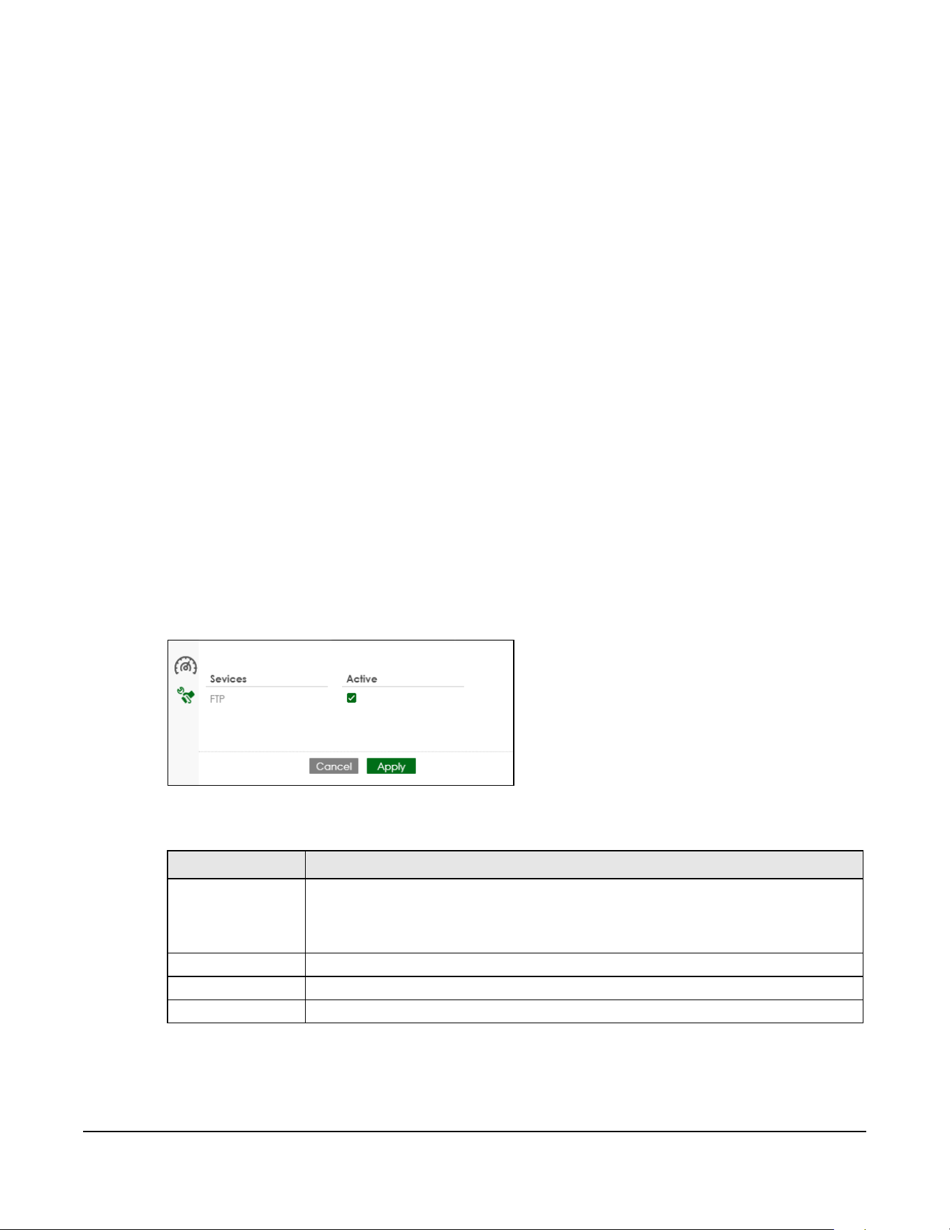
Table 72 Dashboard > Edit Port Settings and Neighbor
LABEL DESCRIPTION
Ports This displays the Ethernet ports on the PoE12-3PD.
Name Enter a name for the port.
Speed/Duplex Select the link speed and duplex mode for the port.
Cancel Click this to reset the fields to the previous configuration.
Apply Click this to save your changes to the PoE12-3PD.
PoE12-3PD User’s Guide
22
CHAPTER 23
Maintenance
23.1 What You Can Do in This Chapter
• The Access Management screen (Section 23.2 on page 22) enables or disables the service you may
use to access the PoE12-3PD.
• The Change Password screen (Section 23.3 on page 22) changes the login password of the PoE12-
3PD.
• The Firmware Upgrade screen (Section 23.4 on page 23) uploads firmware to the PoE12-3PD.
• The Log screen (Section 23.5 on page 24) displays the PoE12-3PD’s log messages.
• The Reboot screen (Section 23.6 on page 24) restarts the PoE12-3PD.
23.2 Access Management Screen
Use the Access Management screen to enable or disable the service you may use to access the PoE12-
3PD. Click Maintenance > Access Management to display the following screen.
Figure 16 Maintenance > Access Management
The following table describes the labels in this screen.
Table 73 Maintenance > Access Management
LABEL DESCRIPTION
Services The service you may use to access the PoE12-3PD is here.
• FTP - Transfer files to and from the PoE12-3PD over a network using the FTP protocol.
ZON Utility uses FTP to upgrade firmware. If you disable FTP, you won’t be able to
upgrade the firmware through the ZON Utility.
Active Select this check box for the service that you want to allow to access the PoE12-3PD.
Cancel Click this to reset the fields to the previous configuration.
Apply Click this to save your changes to the PoE12-3PD.
Chapter 23 Maintenance
PoE12-3PD User’s Guide
23
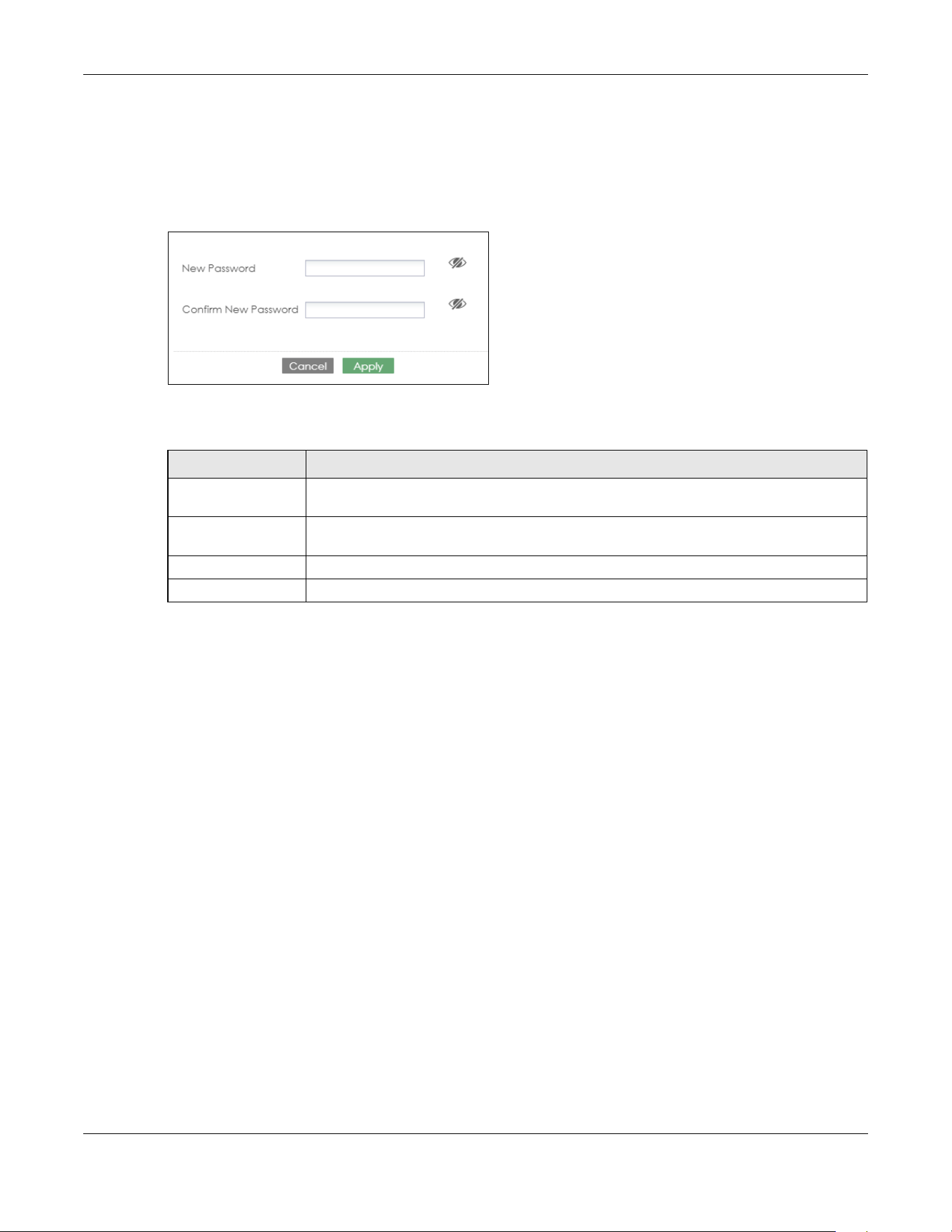
23.3 Change Password
Use the Change Password screen to change the login password of the Web Configurator. Click
Maintenance > Change Password to display the following screen.
Figure 17 Maintenance > Change Password
The following table describes the labels in this screen.
23.4 Firmware Upgrade
You can upgrade the PoE12-3PD’s firmware through the Web Configurator or NCC.
Firmware Upgrade Through NCC
In cloud mode, NCC will first check if the firmware on the PoE12-3PD needs to be upgraded. If it does,
the PoE12-3PD will upgrade the firmware immediately. If the firmware does not need to be upgraded,
but there is newer firmware available for the PoE12-3PD, then it will be upgraded according to the
firmware upgrade schedule for the PoE12-3PD on the NCC.
On the NCC web portal, go to Site-wide > Configure > Firmware management to schedule the firmware
upgrade time.
Note: While the PoE12-3PD is rebooting, do NOT turn off the power.
Firmware Upgrade Through Web Configurator
Use the screen to upgrade your PoE12-3PD to the latest firmware.
Note: Make sure you download and upload (and unzipped) the correct firmware version so
the PoE12-3PD can successfully update the firmware.
Table 74 Maintenance > Change Password
LABEL DESCRIPTION
New Password Enter your new password for the Web Configurator. Alphanumeric characters are allowed
except [ ? ], [ | ], [ ' ], [ " ], [ , ] or [ space ]. The password must be 4 to 63 characters long.
Confirm New
Password
Retype your new password for confirmation.
Cancel Click this to reset the fields to the previous configuration.
Apply Click this to save your changes to the PoE12-3PD.
Chapter 23 Maintenance
PoE12-3PD User’s Guide
24
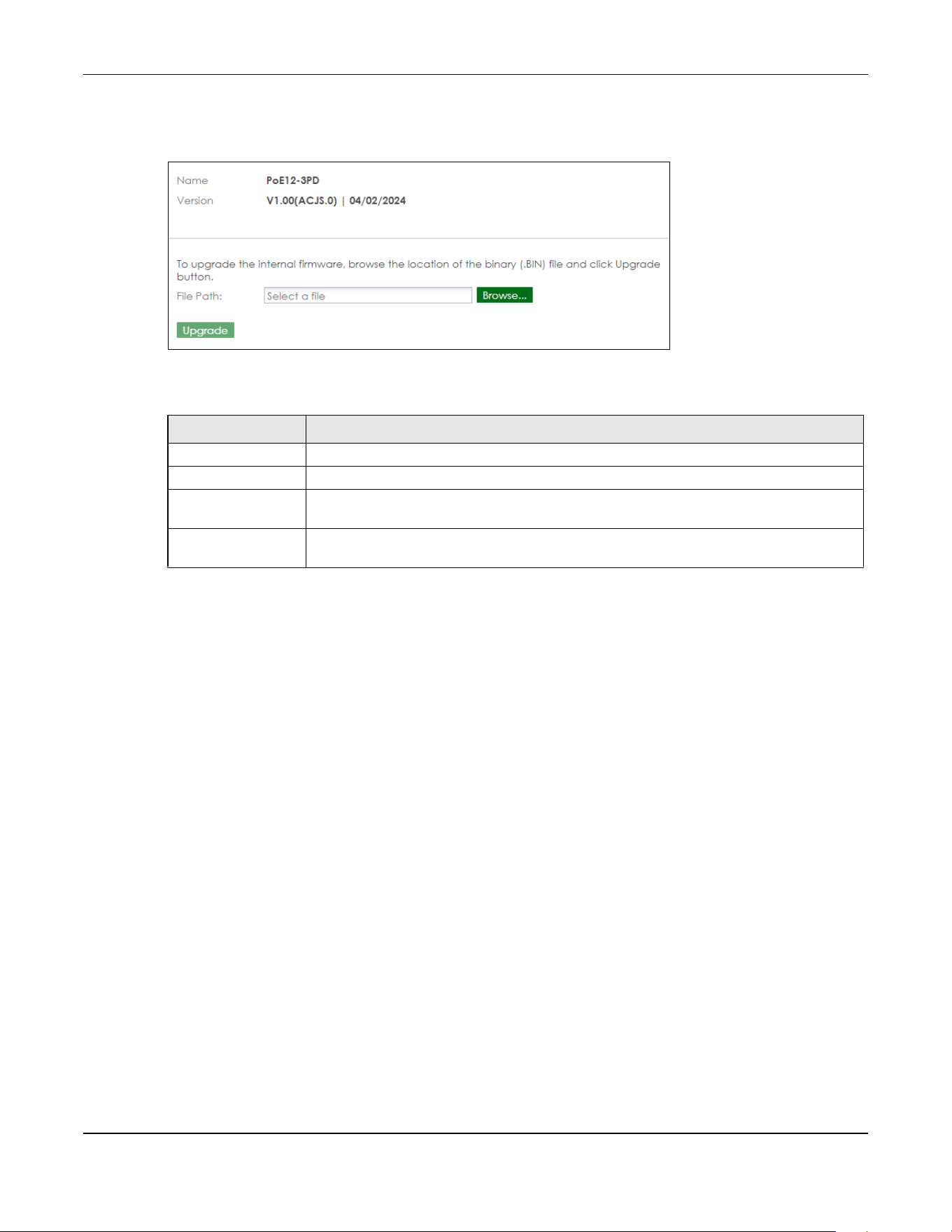
Click Maintenance > Firmware Upgrade to view the screen as shown next.
Figure 18 Maintenance > Firmware Upgrade
The following table describes the labels in this screen.
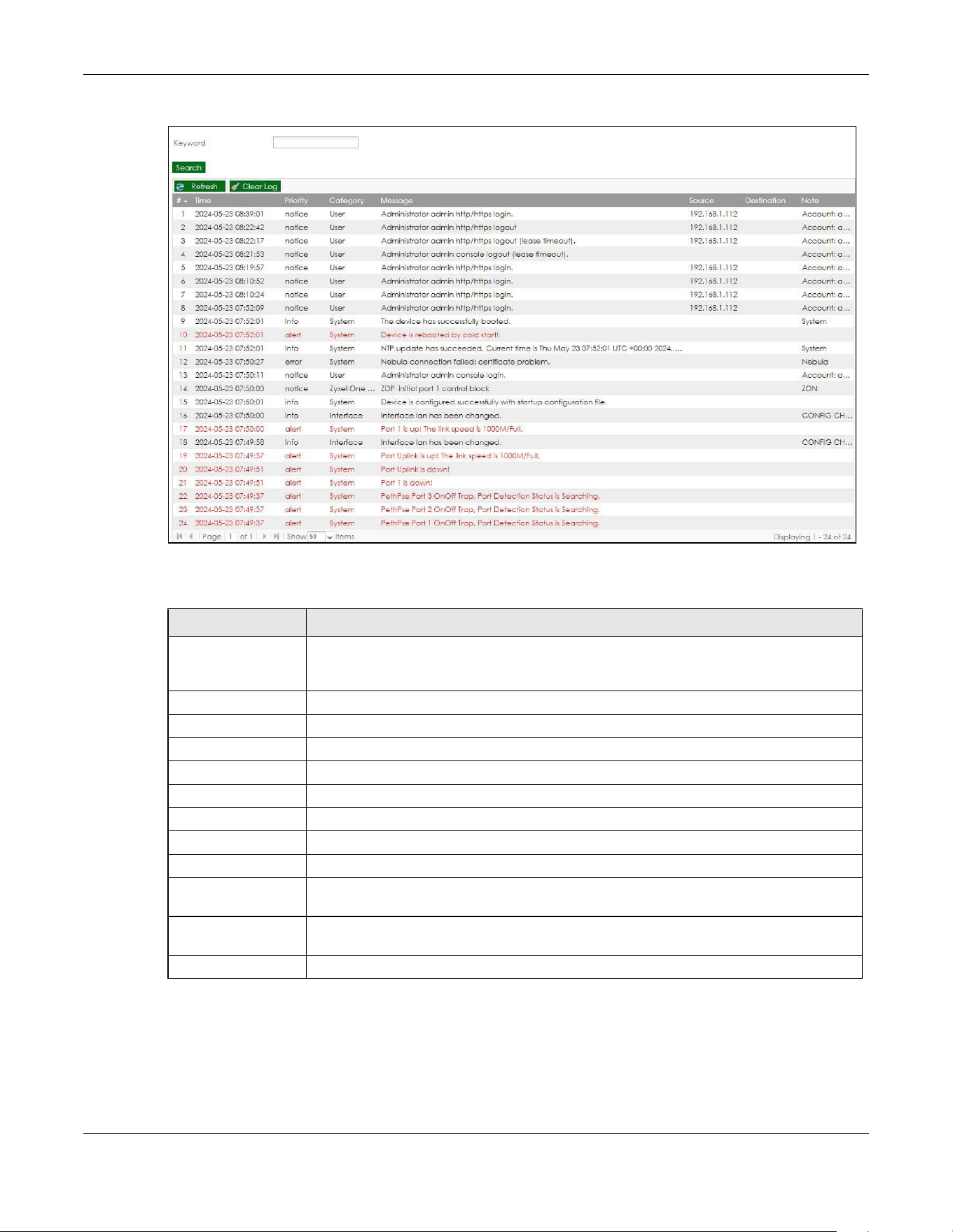
23.5 Log
Use the Log screen to view the log messages of the PoE12-3PD. Click Maintenance > Log to display the
following screen.
Note: When a log reaches the maximum number of log messages, new log messages
automatically overwrite existing log messages, starting with the oldest existing log
message first.
Events that generate an alert (as well as a log message) display in red. Regular logs display in black.
Click a column’s heading cell to sort the table entries by that column’s criteria. Click the heading cell
again to reverse the sort order.
Table 75 Maintenance > Firmware Upgrade
LABEL DESCRIPTION
Name This is the name of the device.
Version This is the firmware version and the date created.
Browse... Click the Browse... button to find the .bin file you want to upload. Remember that you must
decompress compressed (.zip) files before you can upload them.
Upgrade After a successful upgrade, the system will reboot, and you will need to log into the PoE12-
3PD again.
Chapter 23 Maintenance
PoE12-3PD User’s Guide
25
Figure 19 Maintenance > Log
The following table describes the labels in this screen.
23.6 Reboot
Use this screen to restart the PoE12-3PD.
Table 76 Maintenance > Log
LABEL DESCRIPTION
Keyword Type a keyword to look for in the Message, Source, Destination and Note fields. If a match
is found in any field, the log message is displayed. You can use up to 63 alphanumeric
characters begin with a letter. The valid characters are a-z, A-Z, 0-9, '()[]+,/:=?!*@$_-.".
Search Click this button to update the log using the keyword you typed.
Refresh Click this to update the list of logs.
Clear Log Click this to clear the whole log, regardless of what is currently displayed on the screen.
# This field is a sequential value, and it is not associated with a specific log message.
Time This field displays the time the log message was recorded.
Priority This field displays the priority of the log message.
Category This field displays the type of the log.
Message This field displays the reason the log message was generated.
Source This field displays the source IP address of the incoming packet that generated the log
message.
Destination This field displays the IP address of the destination of the incoming packet when the log
message was generated.
Note This field displays any additional information about the log message.
Chapter 23 Maintenance
PoE12-3PD User’s Guide
26
23.6.1 What You Need To Know
If you made changes in the Web Configurator, they were saved when you click Apply. They do not
change when you reboot the PoE12-3PD.
Reboot is different to reset; reset returns the PoE12-3PD to its factory default configuration.
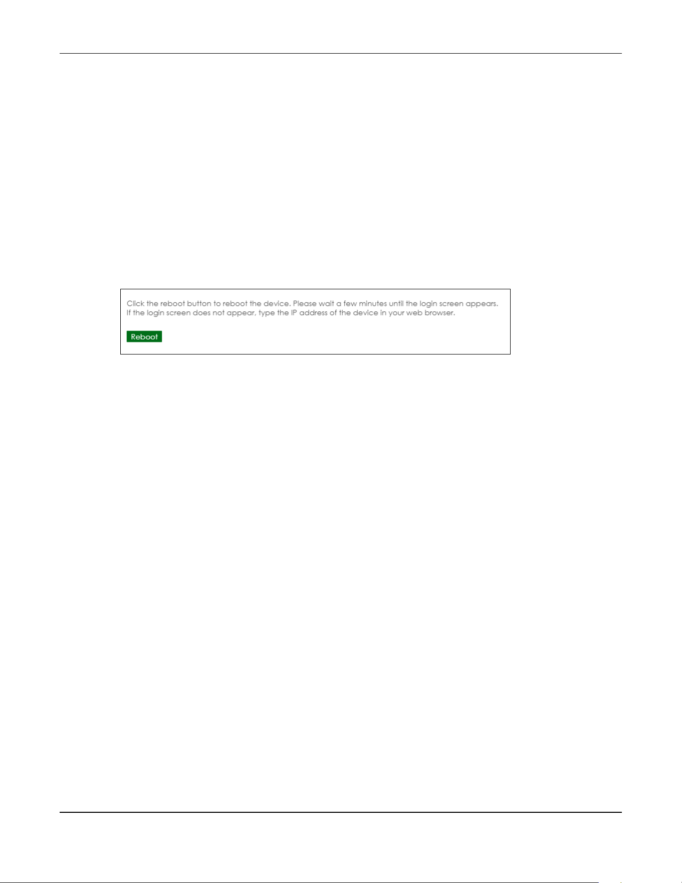
23.6.2 Reboot Screen
You can reboot your PoE12-3PD when the Internet connection is slow or intermittent.
This screen allows you to restart the PoE12-3PD. Click Maintenance > Reboot to display the following
screen. Click Reboot to restart the PoE12-3PD immediately.
Figure 20 Maintenance > Reboot
After the PoE12-3PD reboots, wait a few minutes until the login screen appears. If the login screen does
not appear, type the IP address of the PoE12-3PD in your Web browser.

PoE12-3PD User’s Guide
26
CHAPTER 24
Troubleshooting
This chapter offers some suggestions to solve problems you might encounter. The potential problems are
divided into the following categories.
• Power, Hardware Connections, and LEDs
• Improper Network Cabling and Topology
24.1 Power, Hardware Connections, and LEDs
The PoE12-3PD does not turn on. None of the LEDs turn on.
1 Check that the PoE switch or PoE injector connected to the UPLINK port is a PoE device.
2 Ensure the the Ethernet cable is connected to the UPLINK port and that you're using the supported
Ethernet cable. See Table 60 on page 2 for supported cables.
3 Check that the LEDs are behaving correctly. See Table 66 on page 12.
4 If the problem continues, contact the vendor.
One of the LEDs does not behave as expected.
1 Make sure you understand the normal behavior of the LED. See Section 20.5 on page 12.
2 Check the hardware connections. See Section 20.1 on page 10.
3 Inspect your cables for damage. Contact the vendor to replace any damaged cables.
4 Disconnect and re-connect the power adapter or cord to the PoE12-3PD.
5 If the problem continues, contact the vendor.
The Link LED does not light up when a device is connected.
• Verify that the attached device(s) is turned on and properly connected to your PoE12-3PD.

Chapter 24 Troubleshooting
PoE12-3PD User’s Guide
27
• Make sure the network adapters are working on the attached devices.
• Verify that proper network cable type is used and its length does not exceed 100 meters.
The LEDs of port 1-3 are off and/or power is not being supplied to my Powered Device (PD).
• Ensure to connect the PD to port 1, 2 or 3 of your PoE12-3PD.
• Check your PoE12-3PD’s PoE MAX LED. If it blinks quickly in yellow or is off, the remaining power
budget of the PoE12-3PD is relatively low, and the connected PDs might not have enough power to
function properly. See Section 20.5 on page 12 for more information on LEDs.
• Ensure the UPLINK port of the PoE12-3PD is properly connected to a powered PoE Switch or PoE
injector. Verify that the power source of the PoE Switch or PoE injector is on and working.
• Ensure all the Ethernet cables are properly connected and that you are using the supported Ethernet
cable. See Table 60 on page 2 for supported cables. Contact your local distributor if the problem
persists.
24.2 Improper Network Cabling and Topology
Improper network cabling or topology setup is a common cause of poor network performance or even
network failure.
Figure 16 Troubleshooting Improper Network Cabling and Topology
PROBLEM CORRECTIVE ACTION
Faulty cables Using faulty network cables may affect data rates and have an impact on your
network performance. Replace with new standard network cables.
Non-standard network
cables
Non-standard cables may increase the number of network collisions and cause
other network problems that affect your network performance.
For 1G connections, use Cat5e cable for better speed.
Cabling Length If you use longer cables than are needed, transmission quality may be affected.
The network cables should not be longer than the limit of 100 meters.
Too many hubs between
the computers in the
network
Too many hubs (or repeaters) between the connected computers in the network
may increase the number of network collision or other network problems. Remove
unnecessary hubs from the network.
A loop in the data path A data path loop forms when there is more than one path or route between two
networked computers. This results in broadcast storms that will severely affect your
network performance. Make sure there are no loops in your network topology.

PoE12-3PD User’s Guide
45
APPENDIX A
Customer Support
In the event of problems that cannot be solved by using this manual, you should contact your vendor. If
you cannot contact your vendor, then contact a Zyxel office for the region in which you bought the
device.
For Zyxel Communications offices, see https://service-provider.zyxel.com/global/en/contact-us for the
latest information.
For Zyxel Networks offices, see https://www.zyxel.com/index.shtml for the latest information.
Please have the following information ready when you contact an office.
Required Information
• Product model and serial number.
• Warranty Information.
• Date that you received your device.
• Brief description of the problem and the steps you took to solve it.
Corporate Headquarters (Worldwide)
Taiwan
• Zyxel Communications (Taiwan) Co., Ltd.
• https://www.zyxel.com
Asia
China
• Zyxel Communications Corporation–China Office
• https://www.zyxel.com/cn/sc
India
• Zyxel Communications Corporation–India Office
• https://www.zyxel.com/in/en-in
Kazakhstan
•Zyxel Kazakhstan
• https://www.zyxel.com/ru/ru

Appendix A Customer Support
PoE12-3PD User’s Guide
46
Korea
• Zyxel Korea Co., Ltd.
• http://www.zyxel.kr/
Malaysia
• Zyxel Communications Corp.
• https://www.zyxel.com/global/en
Philippines
• Zyxel Communications Corp.
• https://www.zyxel.com/global/en
Singapore
• Zyxel Communications Corp.
• https://www.zyxel.com/global/en
Taiwan
• Zyxel Communications (Taiwan) Co., Ltd.
• https://www.zyxel.com/tw/zh
Thailand
• Zyxel Thailand Co., Ltd.
• https://www.zyxel.com/th/th
Vietnam
• Zyxel Communications Corporation–Vietnam Office
• https://www.zyxel.com/vn/vi
Europe
Belarus
• Zyxel Communications Corp.
• https://www.zyxel.com/ru/ru
Belgium (Netherlands)
• Zyxel Benelux
• https://www.zyxel.com/nl/nl
• https://www.zyxel.com/fr/fr
Bulgaria
• Zyxel Bulgaria

Appendix A Customer Support
PoE12-3PD User’s Guide
47
• https://www.zyxel.com/bg/bg
Czech Republic
• Zyxel Communications Czech s.r.o.
• https://www.zyxel.com/cz/cs
Denmark
• Zyxel Communications A/S
• https://www.zyxel.com/dk/da
Finland
• Zyxel Communications
• https://www.zyxel.com/fi/fi
France
•Zyxel France
• https://www.zyxel.com/fr/fr
Germany
•Zyxel Deutschland GmbH.
• https://www.zyxel.com/de/de
Hungary
• Zyxel Hungary & SEE
• https://www.zyxel.com/hu/hu
Italy
• Zyxel Communications Italy S.r.l.
• https://www.zyxel.com/it/it
Norway
• Zyxel Communications A/S
• https://www.zyxel.com/no/no
Poland
• Zyxel Communications Poland
• https://www.zyxel.com/pl/pl
Romania
• Zyxel Romania
• https://www.zyxel.com/ro/ro

Appendix A Customer Support
PoE12-3PD User’s Guide
48
Russian Federation
• Zyxel Communications Corp.
• https://www.zyxel.com/ru/ru
Slovakia
•Zyxel Slovakia
• https://www.zyxel.com/sk/sk
Spain
• Zyxel Iberia
• https://www.zyxel.com/es/es
Sweden
• Zyxel Communications A/S
• https://www.zyxel.com/se/sv
Switzerland
•Studerus AG
• https://www.zyxel.com/ch/de-ch
• https://www.zyxel.com/fr/fr
Turkey
• Zyxel Turkey A.S.
• https://www.zyxel.com/tr/tr
UK
• Zyxel Communications UK Ltd.
• https://www.zyxel.com/uk/en-gb
Ukraine
•Zyxel Ukraine
• https://www.zyxel.com/ua/uk-ua
South America
Argentina
• Zyxel Communications Corp.
• https://www.zyxel.com/co/es-co
Brazil
• Zyxel Communications Brasil Ltda.

Appendix A Customer Support
PoE12-3PD User’s Guide
49
• https://www.zyxel.com/br/pt
Colombia
• Zyxel Communications Corp.
• https://www.zyxel.com/co/es-co
Ecuador
• Zyxel Communications Corp.
• https://www.zyxel.com/co/es-co
South America
• Zyxel Communications Corp.
• https://www.zyxel.com/co/es-co
Middle East
Israel
• Zyxel Communications Corp.
• https://il.zyxel.com
North America
USA
• Zyxel Communications, Inc. – North America Headquarters
• https://www.zyxel.com/us/en-us

PoE12-3PD User’s Guide
50
APPENDIX B
Legal Information
Copyright
Copyright © 2024 by Zyxel and/or its affiliates.
The contents of this publication may not be reproduced in any part or as a whole, transcribed, stored in a retrieval system, translated into any
language, or transmitted in any form or by any means, electronic, mechanical, magnetic, optical, chemical, photocopying, manual, or
otherwise, without the prior written permission of Zyxel and/or its affiliates.
Published by Zyxel and/or its affiliates. All rights reserved.
Disclaimer
Zyxel does not assume any liability arising out of the application or use of any products, or software described herein. Neither does it convey any
license under its patent rights nor the patent rights of others. Zyxel further reserves the right to make changes in any products described herein
without notice. This publication is subject to change without notice.
Regulatory Notice and Statement
United States of America
The following information applies if you use the product within USA area.
US Importer: Zyxel Communications, Inc, 1130 North Miller Street Anaheim, CA92806-2001, https://www.zyxel.com/us/en/
Federal Communications Commission (FCC) EMC Statement
• This device complies with Part 15 of FCC rules. Operation is subject to the following two conditions:
(1) This device may not cause harmful interference.
(2) This device must accept any interference received, including interference that may cause undesired operations.
• Changes or modifications not expressly approved by the party responsible for compliance could void the user’s authority to operate the
equipment.
• This equipment has been tested and found to comply with the limits for a Class A digital device, pursuant to part 15 of the FCC Rules. These
limits are designed to provide reasonable protection against harmful interference when the equipment is operated in a commercial
environment. This equipment generates, uses, and can radiate radio frequency energy and, if not installed and used in accordance with the
instruction manual, may cause harmful interference to radio communications. Operation of this equipment in a residential area is likely to
cause harmful interference in which case the user will be required to correct the interference at his own expense.
Canada
The following information applies if you use the product within Canada area.
Innovation, Science and Economic Development Canada ICES statement
CAN ICES-3 (A)/NMB-3(A)
European Union and United Kingdom
The following information applies if you use the product within the European Union and United Kingdom.
EMC statement
WARNING: This equipment is compliant with Class A of EN55032. In a residential environment this equipment may cause radio interference.

Appendix B Legal Information
PoE12-3PD User’s Guide
51
List of National Codes
Safety Warnings
• The protective earthing conductor must be installed by a technician.
• Do NOT use this device near water, for example, in a wet basement or near a swimming pool.
• Do NOT expose your device to dampness, dust or corrosive liquids.
• Do NOT store things on the device.
• Do NOT obstruct the device ventilation slots as insufficient airflow may harm your device. For example, do not place the device in an
enclosed space such as a box or on a very soft surface such as a bed or sofa.
• Do NOT install or service this device during a thunderstorm. There is a remote risk of electric shock from lightning.
• Connect ONLY suitable accessories to the device.
• Do NOT open the device or unit. Opening or removing covers can expose you to dangerous high voltage points or other risks. Only qualified
service personnel should service or disassemble this device. Please contact your vendor for further information.
• Make sure to connect the cables to the correct ports.
• Place connecting cables carefully so that no one will step on them or stumble over them.
• Always disconnect all cables from this device before servicing or disassembling.
• Do NOT remove the plug and connect it to a power outlet by itself; always attach the plug to the power adaptor first before connecting it to
a power outlet.
• Do NOT allow anything to rest on the power adaptor or cord and do NOT place the device where anyone can walk on the power adaptor
or cord.
• Please use the provided or designated connection cables/power cables/adaptors. Connect it to the right supply voltage (for example, 120V
AC in North America or 230V AC in Europe). If the power adaptor or cord is damaged, it might cause electrocution. Remove it from the
device and the power source, repairing the power adapter or cord is prohibited. Contact your local vendor to order a new one.
• Do NOT use the device outside, and make sure all the connections are indoors. There is a remote risk of electric shock from lightning.
• CAUTION: RISK OF EXPLOSION IF BATTERY IS REPLACED BY AN INCORRECT TYPE, DISPOSE OF USED BATTERIES ACCORDING TO THE INSTRUCTION.
Dispose them at the applicable collection point for the recycling of electrical and electronic device. For detailed information about
recycling of this device, please contact your local city office, your household waste disposal service or the store where you purchased the
device.
• Use ONLY power wires of the appropriate wire gauge for your device. Connect it to a power supply of the correct voltage.
• Fuse Warning! Replace a fuse only with a fuse of the same type and rating.
• The POE (Power over Ethernet) devices that supply or receive power and their connected Ethernet cables must all be completely indoors.
• The following warning statements apply, where the disconnect device is not incorporated in the device or where the plug on the power
supply cord is intended to serve as the disconnect device,
– For PERMANENTLY CONNECTED DEVICES, a readily accessible disconnect device shall be incorporated external to the device;
– For PLUGGABLE DEVICES, the socket-outlet shall be installed near the device and shall be easily accessible.
• This device must be grounded by qualified service personnel. Never defeat the ground conductor or operate the device in the absence of a
suitably installed ground conductor. Contact the appropriate electrical inspection authority or an electrician if you are uncertain that
suitable grounding is available.
• If your device has an earthing screw (frame ground), connect the screw to a ground terminal using an appropriate AWG ground wire. Do this
before you make other connections.
• If your device has no earthing screw, but has a 3-prong power plug, make sure to connect the plug to a 3-hole earthed socket.
• When connecting or disconnecting power to hot-pluggable power supplies, if offered with your system, observe the following guidelines:
– Install the power supply before connecting the power cable to the power supply.
– Unplug the power cable before removing the power supply.
– If the system has multiple sources of power, disconnect power from the system by unplugging all power cables from the power supply.
• Do not put the device in a place that is humid, dusty or has extreme temperatures as these conditions may harm your device.
• Please refer to the device back label, datasheet, box specifications or catalog information for the power rating of the device and operating
temperature.
COUNTRY ISO 3166 2 LETTER CODE COUNTRY ISO 3166 2 LETTER CODE
Austria AT Liechtenstein LI
Belgium BE Lithuania LT
Bulgaria BG Luxembourg LU
Croatia HR Malta MT
Cyprus CY Netherlands NL
Czech Republic CZ Norway NO
Denmark DK Poland PL
Estonia EE Portugal PT
Finland FI Romania RO
France FR Serbia RS
Germany DE Slovakia SK
Greece GR Slovenia SI
Hungary HU Spain ES
Iceland IS Sweden SE
Ireland IE Switzerland CH
Italy IT Turkey TR
Latvia LV United Kingdom GB
Appendix B Legal Information
PoE12-3PD User’s Guide
52
Important Safety Instructions
1 Warning! Energy Hazard. Remove all metal jewelry, watches, and so on from your hands and wrists
before serving the PoE12-3PD.
2 Caution! The RJ-45 jacks are not used for telephone line connection.
3 Hazardous Moving Parts. Keep body parts away from fan blades.
4 Hot Surface. Do not touch.
1 Avertissement: Risque de choc électrique. Retirer tout bijoux en métal et votre montre de vos mains et
poignets avant de manipuler cet appareil.
2 Attention: Les câbles RJ-45 ne doivent pas être utilisés pour les connections téléphoniques.
3 Mobilité des pièces détachées. S'assurer que les pièces détachées ne sont pas en contact avec
les pales du ventilateur.
4 Surface brûlante. Ne pas toucher.
Environment Statement
Disposal and Recycling Information
The symbol below means that according to local regulations your product and/or its battery shall be disposed of separately from domestic
waste. If this product is end of life, take it to a recycling station designated by local authorities. At the time of disposal, the separate collection of
your product and/or its battery will help save natural resources and ensure that the environment is sustainable development.
Die folgende Symbol bedeutet, dass Ihr Produkt und/oder seine Batterie gemäß den örtlichen Bestimmungen getrennt vom Hausmüll entsorgt
werden muss. Wenden Sie sich an eine Recyclingstation, wenn dieses Produkt das Ende seiner Lebensdauer erreicht hat. Zum Zeitpunkt der
Entsorgung wird die getrennte Sammlung von Produkt und/oder seiner Batterie dazu beitragen, natürliche Ressourcen zu sparen und die Umwelt
und die menschliche Gesundheit zu schützen.
El símbolo de abajo indica que según las regulaciones locales, su producto y/o su batería deberán depositarse como basura separada de la
doméstica. Cuando este producto alcance el final de su vida útil, llévelo a un punto limpio. Cuando llegue el momento de desechar el
producto, la recogida por separado éste y/o su batería ayudará a salvar los recursos naturales y a proteger la salud humana y
medioambiental.
Le symbole ci-dessous signifie que selon les réglementations locales votre produit et/ou sa batterie doivent être éliminés séparément des ordures
ménagères. Lorsque ce produit atteint sa fin de vie, amenez-le à un centre de recyclage. Au moment de la mise au rebut, la collecte séparée
de votre produit et/ou de sa batterie aidera à économiser les ressources naturelles et protéger l'environnement et la santé humaine.
Il simbolo sotto significa che secondo i regolamenti locali il vostro prodotto e/o batteria deve essere smaltito separatamente dai rifiuti domestici.
Quando questo prodotto raggiunge la fine della vita di servizio portarlo a una stazione di riciclaggio. Al momento dello smaltimento, la raccolta
separata del vostro prodotto e/o della sua batteria aiuta a risparmiare risorse naturali e a proteggere l'ambiente e la salute umana.
Symbolen innebär att enligt lokal lagstiftning ska produkten och/eller dess batteri kastas separat från hushållsavfallet. När den här produkten når
slutet av sin livslängd ska du ta den till en återvinningsstation. Vid tiden för kasseringen bidrar du till en bättre miljö och mänsklig hälsa genom att
göra dig av med den på ett återvinningsställe.
Appendix B Legal Information
PoE12-3PD User’s Guide
53
台灣
以下訊息僅適用於產品銷售至台灣地區
• 這是甲類的資訊產品,在居住的環境中使用時,可能會造成射頻干擾,在這種情況下,使用者會被要求採取某些適當的對策。
• 為避免電磁干擾,本產品不應安裝或使用於住宅環境。
安全警告 – 為了您的安全,請先閱讀以下警告及指示 :
• 請勿將此產品接近水、火焰或放置在高溫的環境。
• 避免設備接觸
– 任何液體 - 切勿讓設備接觸水、雨水、高濕度、污水腐蝕性的液體或其他水份。
– 灰塵及污物 - 切勿接觸灰塵、污物、沙土、食物或其他不合適的材料。
• 雷雨天氣時,不要安裝或維修此設備。有遭受電擊的風險。
• 切勿重摔或撞擊設備,並勿使用不正確的電源變壓器。
• 若接上不正確的電源變壓器會有爆炸的風險。
• 請勿隨意更換產品內的電池。
• 如果更換不正確之電池型式,會有爆炸的風險,請依製造商說明書處理使用過之電池。
• 請將廢電池丟棄在適當的電器或電子設備回收處。
• 請勿將設備解體。
• 請勿阻礙設備的散熱孔,空氣對流不足將會造成設備損害。
• 請使用隨貨提供或指定的連接線 / 電源線 / 電源變壓器,將其連接到合適的供應電壓 ( 如 : 台灣供應電壓 110 伏特 )。
• 假若電源變壓器或電源變壓器的纜線損壞,請從插座拔除,若您還繼續插電使用,會有觸電死亡的風險。
• 請勿試圖修理電源變壓器或電源變壓器的纜線,若有毀損,請直接聯絡您購買的店家,購買⼀個新的電源變壓器。
• 請勿將此設備安裝於室外,此設備僅適合放置於室內。
• 請勿隨⼀般垃圾丟棄。
• 請參閱產品背貼上的設備額定功率。
• 請參考產品型錄或是彩盒上的作業溫度。
• 設備必須接地,接地導線不允許被破壞或沒有適當安裝接地導線,如果不確定接地方式是否符合要求可聯繫相應的電氣檢驗機構檢驗。
• 如果您提供的系統中有提供熱插拔電源,連接或斷開電源請遵循以下指導原則 :
– 先連接電源線至設備連,再連接電源。
– 先斷開電源再拔除連接至設備的電源線。
– 如果系統有多個電源,需拔除所有連接至電源的電源線再關閉設備電源。
• 產品沒有斷電裝置或者採用電源線的插頭視為斷電裝置的⼀部分,以下警語將適用 :
– 對永久連接之設備, 在設備外部須安裝可觸及之斷電裝置;
– 對插接式之設備, 插座必須接近安裝之地點而且是易於觸及的。
About the Symbols
Various symbols are used in this product to ensure correct usage, to prevent danger to the user and others, and to prevent property damage.
The meaning of these symbols are described below. It is important that you read these descriptions thoroughly and fully understand the
contents.
Explanation of the Symbols
Viewing Certifications
Go to http://www.zyxel.com to view this product’s documentation and certifications.
SYMBOL EXPLANATION
Alternating current (AC):
AC is an electric current in which the flow of electric charge periodically reverses direction.
Direct current (DC):
DC if the unidirectional flow or movement of electric charge carriers.
Earth; ground:
A wiring terminal intended for connection of a Protective Earthing Conductor.
Class II equipment:
The method of protection against electric shock in the case of class II equipment is either double insulation
or reinforced insulation.

Appendix B Legal Information
PoE12-3PD User’s Guide
54
Zyxel Limited Warranty
Zyxel warrants to the original end user (purchaser) that this product is free from any defects in material or workmanship for a specific period (the
Warranty Period) from the date of purchase. The Warranty Period varies by region. Check with your vendor and/or the authorized Zyxel local
distributor for details about the Warranty Period of this product. During the warranty period, and upon proof of purchase, should the product
have indications of failure due to faulty workmanship and/or materials, Zyxel will, at its discretion, repair or replace the defective products or
components without charge for either parts or labor, and to whatever extent it shall deem necessary to restore the product or components to
proper operating condition. Any replacement will consist of a new or re-manufactured functionally equivalent product of equal or higher value,
and will be solely at the discretion of Zyxel. This warranty shall not apply if the product has been modified, misused, tampered with, damaged by
an act of God, or subjected to abnormal working conditions.
Note
Repair or replacement, as provided under this warranty, is the exclusive remedy of the purchaser. This warranty is in lieu of all other warranties,
express or implied, including any implied warranty of merchantability or fitness for a particular use or purpose. Zyxel shall in no event be held
liable for indirect or consequential damages of any kind to the purchaser.
To obtain the services of this warranty, contact your vendor. You may also refer to the warranty policy for the region in which you bought the
device at https://www.zyxel.com/global/en/support/warranty-information.
Registration
Register your product online at www.zyxel.com to receive email notices of firmware upgrades and related information.
Trademarks
The trademarks mentioned in this publication are used for identification purposes only and may be properties of their respective owners.

Index
PoE12-3PD User’s Guide
55
Index
C
cable
PoE 9
supported 9
Cabling Length 44
certifications
viewing 53
contact information 45
copyright 50
customer support 45
D
device name
configuration 32
disclaimer 50
disposal and recycling information
EU 52
E
EMC statement 50
Environment Statement 52
F
Faulty cables 44
FCC interference statement 50
feature comparison 9
features
PoE Extender 9
firmware version 32
front panel 20
G
gateway 32
Guide
Quick Start 2
H
hardware overview 20
I
IEEE 802.3af 9
IEEE 802.3at 9
IEEE 802.3bt 9
IEEE standard 9
Innovation, Science and Economic Development
Canada ICES statement 50
Internet browser
pop-up window 29
supported 29
IP address 32
J
Java permissions 29
JavaScript 29
L
LED
PoE MAX 26
PWR 25
link status 32
login 29

Index
PoE12-3PD User’s Guide
56
M
MAC address 32
management method 8
managing the device
good habits 19
model name 32
multi-gigabit Ethernet 9
N
Nebula Mobile App 19
Nebula web portal 12
network applications 9
Network Cable Types 21, 25
Network Time Protocol (NTP) 36
Non-standard network cables 44
P
password
good habit 19
PD (Powered Device) 9
PoE 44
PoE MAX
LED 26
PoE standard 9
PoE standards table 9
PoE type 9
port
voltage range 9
power
port 9
power per port
maximum 9
Powered Device (PD) 9
product registration 54
PWR
LED 25
Q
Quick Start Guide 2
R
registration
product 54
Regulatory Notice and Statement 50
S
safety warnings 51
screen resolution
recommended 29
Switch
IPv4 address 32
model name 32
System
login 29
System screen 31
T
time servers (default) 36
trademarks 54
Troubleshooting
Improper Network Cabling and Topology 44
twisted pairs
used 9
U
unregister
Switch 14
V
voltage range