
Installation Guide
GV-POEX0111 Gigabit Waterproof PoE Extender
Packing List
When using this product for the first time, carefully open the packing box. The packing box should
contain the following items:
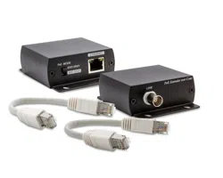
➢ GV-POEX0111
➢ Waterproof Connector x 2
➢ Installation Guide
★ Ships locked to the fuselage
Note: Precision devices are built into the device, please handle them carefully to avoid violent
vibration, which may affect the performance of the device. If you find that the equipment is
damaged or any parts are lost in the transportation process, please inform us, and we will give you a
proper solution as soon as possible.
1
Chapter 1 Product Introduction
1.1 Product Overview
GV-POEX0111 is a gigabit waterproof PoE extender, which provides two 10/100/1000 Mbps RJ-45
ports. The input port is connected to the PSE device, and the output port is connected to the PD
device. No configuration is needed; plug and play.
Chapter 2 Product Appearance Description
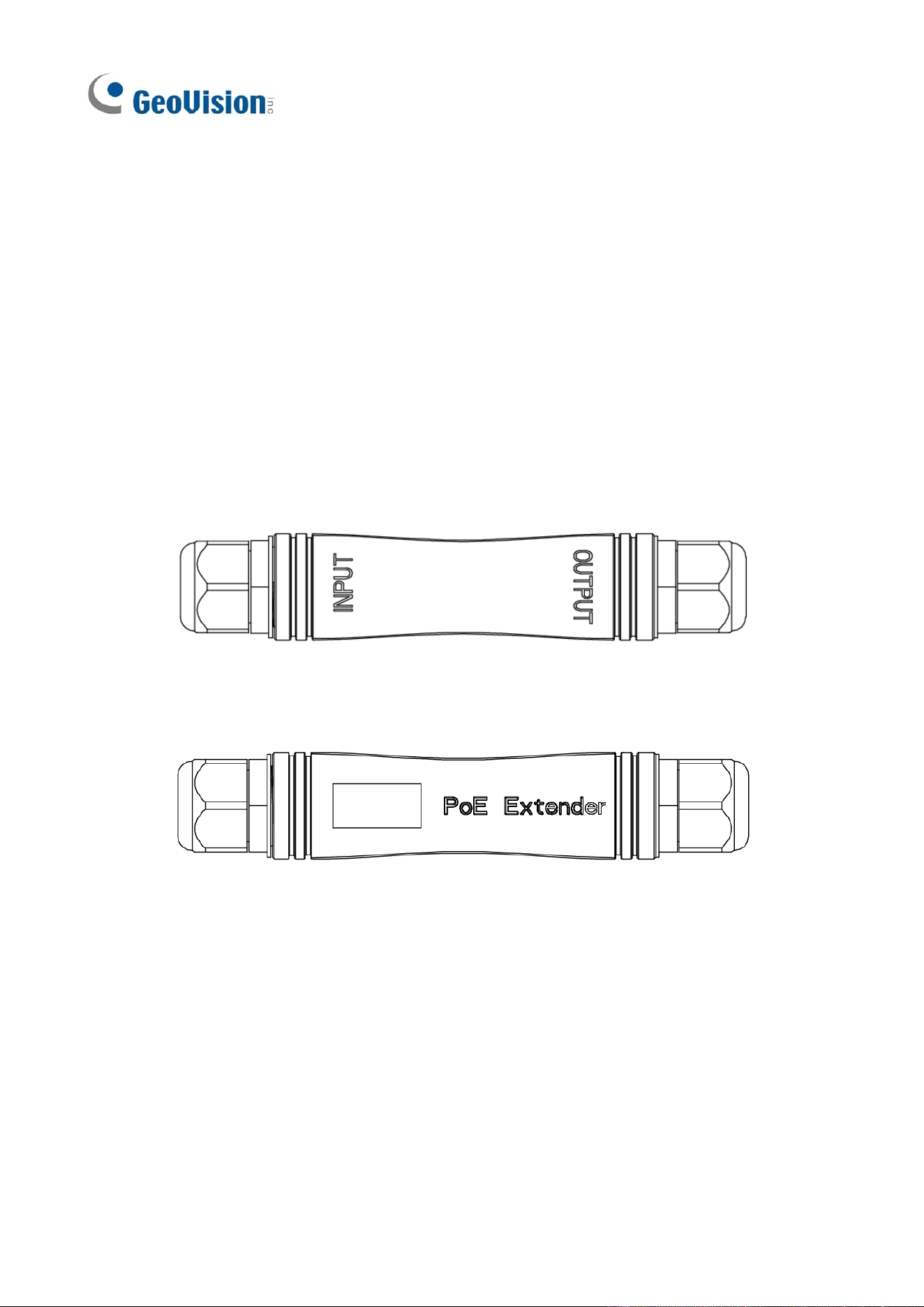
2.1 Front Panel
The front side consists of input and output ports, as shown in the figure below:
Figure 2-1 GV-POEX0111 front view
2.2 Back Panel
Figure 2-2 GV-POEX0111 back view
2.3 Left Panel
Figure 2-3 GV-POEX0111 left-side view

2
Chapter 3 User Guide
The purpose of this section is to help users properly install and safely use this device.
3.1 Notes on Installation and Use
Precautions: To avoid equipment damage and personal injury caused by improper use, please
follow the following precautions:
➢ Waterproof joint nuts and joints must be tightened, otherwise water will damage the machine.
➢ The equipment should work within the temperature and humidity range permitted by the
technical indicators.
➢ Please use with PoE devices conforming to IEEE 802.3af/at standards.
➢ Please do not install the equipment in a severe vibration environment.
➢ In case of failure, do not open the case without authorization, and contact professional
maintenance.
3.2 Application Schematic
Note the direction of INPUT and OUTPUT in the GV-POEX0111 application schematic.
➢ When using a single extender, connect the INPUT port to the PoE switch and the OUTPUT port
to the PD device. This setup can transmit up to 200 m with any switch or single-port PoE
adapter compatible with IEEE 802.3af/at, and up to 400 m with GV-APOE switches in CCTV
mode.
➢ When using two extenders together, connect the INPUT port of one extender to the PoE switch,
the OUTPUT port of that extender to the INPUT port of the second extender, and the OUTPUT
port of the second extender to the PD device. This setup can transmit up to 330 m with any
switch or single-port PoE adapter compatible with IEEE 802.3af/at, and up to 600 m with
GV-APOE switches in CCTV mode.
➢ When using three extenders together, connect the INPUT port of one extender to the PoE
switch, the OUTPUT port of that extender to the INPUT port of the second extender, the
OUTPUT port of the second extender to the INPUT port of the third extender, and the OUTPUT
port of the third extender to the PD device. This setup can transmit up to 460 m with any switch
or single-port PoE adapter compatible with IEEE 802.3af/at, and up to 800 m with GV-APOE
switches in CCTV mode.
Up to three extenders are connected, with the maximum PoE power reaching the end being
10.02 W with any switch or single-port PoE adapter compatible with IEEE 802.3af/at, and 5.52 W
with GV-APOE switches in CCTV mode, using Cat 5e cable.

3
Figure 3-1 GV-POEX0111 application schematic
Note:
1. We do not recommend connecting other GV or third-party PoE extenders in series with the
GV-POEX0111.
2. This figure, based on using UTP Cat 5e or Cat 6 cable as an example, shows that the maximum
distance from the switch port to the terminal PD is 800 m. At this distance, the maximum
power delivered to the PD is 5.52 W for Cat 5e, with higher power available for higher levels of
Cat cables. The front-end device (PoE switch) and end device (IP camera) in the application
must both support the transmission distance and the implied rates based on the PoE switch
type specified in the topology diagram.