SWAINS
®
MODEL NUMBER 917.373460 OWNER'SMANUAL
oAssembly
oOperation
• Customer
Responsibilities
oService
oAdjustments
oRepair Parts
Caution:
Read and Follow
all Safety Rules
and Instructions
Before Operating
This Equipment
SAFETY RULES
CAUTION: ALWAYSDISCONNECTSPARKPLUGWIREANDPLACEWIREWHEREITCANNOT CONTACTSPARK
PLUG TO PREVENT ACCIDENTAL STARTING WHEN SETTINGUP, TRANSPORTING, ADJUSTING OR MAKING
REPA,RS. IMPORTANT
SAFETY STANDARDS REQUIRE OPERATOR PRESENCE CONTROLSTO MINIMIZETHE RISK OFINJURY. YOUR UNITIS EQUIPPED WITH
SUCH CONTROLS, DO NOT ATTEMPT TO DEFEAT THE FUNCTION OF THE OPERATOR PRESENCE CONTROLS UNDER ANY CIRCUM-
STANCES,
TRAINING:
• Read this operator's manual carefully. Become familiar with
the controls and know how to operate your mower properly
Learn how to quickly stop mower.
Do not allow children to use your mower Never allow adults
to use mower without proper instructions
Keep the area of operation clear of all persons, especially
small children and pets
• Use mower only as the manufacturer intended and as de-
scribed in this manual.
Do not operate mower if it has been dropped or damaged in
arty manner Always have damage repaired before using
your mower
Do not use accessory attachments that are not recom-
mended by the manufacturer_ Use of such attachments may
be hazardous
Be aware that the mower blade turns when the engine is
running.
PREPARATION:
Always thoroughly check the area to be mowed and clear it
of all stones, sticks, wires, bones, and other foreign objects
These objects will be thrown by the blade and can cause
severe injury
Always wear safety glasses or eye shields when starting and
while using your mower
Dress properly Do not operate mower when barefoot or
wearing open sandals Wear only solid shoes with good
traction when mowing
Check fuel tank before starting engine. Do not fill gas tank
indoors, when the engine is running or when the engine ishot
Allow the engine to cool for several minutes before filling the
gas tank Clean off any spilled gasoline before starting the
engine.
Always make wheel height adjustments before starting your
mower Never attempt to do this while the engine is running
Mow only in daylight or good artificial light
OPERATION:
Keep your eyes and mind on your mower and the area being
cut Do not let other interests distract you_
Do not mow wet or slippery grass Never run while operating
your mower. Always be sure of your footing - keep a firm hold
on the handles and walk
Do not put hands or feet near or under rotating parts_ Keep
clear of the discharge opening at al! times
Always stop the engine whenever you leave or are not using
your mower, or before crossing driveways, walks, roads, and
arty gravel-covered areas.
Never direct discharge of material toward bystanders nor
allow anyone near the mower while you are operating it
Before cleaning, irrspecting, or repairing your mower, stop
the engine and make absolutely sure the blade and all
moving parts have stopped_ Then disconnect the spark plug
wire and keep it away from the spark plug to prevent
accidental starting
Do not continue to run your mower ifyou hit a foreign object
Follow the procedure outlined above, then repair any dam-
age before restarting and operating you mower.
Do not change the governor settings or overspeed the
engine Engine damage or personal injury may result
Do not operate your mower if it vibrates abnormally. Exces-
sive vibration is an indication of damage; stop the engine,
safely check for the cause of vibration and repair as required
Do not runthe engine indoors Exhaust fumes are danger-
ous
Never cut grass by pulling the mower towards you. Mow
across the face of slopes, never up and down or you might
lose your footing. Do not mow excessively steep slopes
Use caution when operating the mower on uneven terrain or
when changing directions - maintain good footing.
Never operate your mower without proper guards, plates,
grass catcher or other safety devices in place.
MAINTENANCE AND STORAGE:
Check the blade and the engine mounting bolts often to be
sure they are tightened properly
Check all bolts, nuts and screws at frequent intervals for
proper tightness to be sure mower is in safe working condi-
tion.
Keep all safety devices in place and working.
To reduce fire hazard, keep the engine free of grass, leaves
or excessive grease and oil.
Check grass catcher often for deterioration and wear and
replace worn bags. Use only replacement bags that are
recommended by and comply with specifications of the
manufacturer of your mower.
Always keep a sharp blade on your mower.
Allow engine to coot before stodng in any enclosure
Never store mower with fuel in the tank inside a building
where fumes may reach an open flame or an ignition source
such as a hot water heater, space heater, clothes dryer, etc.
I
LOOK FOR THIS SYMBOL 'TO POINT OUT IMPORTANT SAFETY PRECAUTIONS.
IT MEANS - ATTENTION!!! BECOME ALERT!!! YOUR SAFETY IS INVOLVED.
2
I
CONGRATULATIONS on your purchase of a Sears Lawn
Mower It has been designed, engineered and manufac-
tured to give you the best possible dependability and
performance
Should you experience any problem you cannot easily
remedy, please contact your nearest Sears Authorized
Service CentedDepartmenL We have competent, well-
trained technicians and the proper tools to service or repair
this lawn mower_
Please read and retain this manual The instructions will
enable you to assemble and maintain your lawn mower
properly. Always observe the "SAFETY RULES"
MODEL
NUMBER 917373460
SERIAL
NUMBER
DATEOFPURCHASE
THE MODELAND SERIALNUMBERSWILL BEFOUND
ON A DECAL ATTACHED TO THE REAR OF THE
LAWN MOWER HOUSING.
YOUSHOULDRECORDBOTHSERIALNUMBERAND
DATE OF PURCHASE AND KEEP IN A SAFE PLACE
FOR FUTURE REFERENCE.
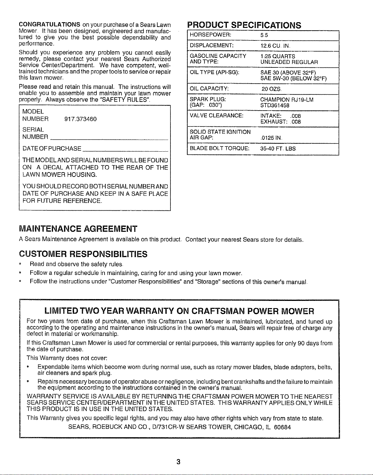
PRODUCT SPECIFICATIONS
HORSEPOWER: 5.5
DISPLACEMENT: 126 CU. IN.
GASOLINE CAPACITY 1_25QUARTS
AND TYPE: UNLEADED REGULAR
OIL TYPE (API-SG): SAE 30 (ABOVE 32°F)
SAE 5W-30 (BELOW 32°F)
OIL CAPACITY: 20 OZS
SPARK PLUG: CHAMPION RJ19-LM
GAP: 030") STD361458
VALVE CLEARANCE: INTAKE: .008
EXHAUST: 008
SOLID STATE IGNITION
AIR GAP: .0!25 IN.
BLADE BOLTTORQUE: 35-40 FT. LBS
MAMNTENANCE AGREEMENT
A Sears Maintenance Agreement is available on this producL Contact your nearest Sears store for details.
CUSTOMER RESPONSiBILiTiES
o Read and observe the safety rules.
Follow a regular schedule in maintaining, caring for and using your lawn mower.
o Follow the instructions under "Customer Responsibilities" and "Storage" sections of this owner's manual.
LiMiTED TWO YEAR WARRANTY ON CRAFTSMAN POWER MOWER
For two years from date of purchase, when this Craftsman Lawn Mower is maintained, lubricated, and tuned up
according to the operating and maintenance instructions in the owner's manual, Sears will repair free of charge any
defect in material or workmanship.
If this Craftsman Lawn Mower is used for commercial or rental purposes, this warranty applies for only 90 days from
the date of purchase.
This Warranty does not cover:
Expendable items which become worn during normal use, such as rotary mower blades, blade adapters, belts,
air cleaners and spark plug.
Repairs necessary because of operator abuse or negligence, including bent crankshafts and the failure to maintain
the equipment according to the instructions contained in the owner's manual
WARRANTY SERVICE IS AVAILABLE BY RETURNING THE CRAFTSMAN POWER MOWER TO THE NEAREST
SEARS SERVICE CENTER/DEPARTMENT INTHE UNITED STATES. THIS WARRANTY APPLIES ONLY WHILE
THIS PRODUCT IS IN USE IN THE UNITED STATE&
This Warranty gives you specific legal rights, and you may also have other rights which vary from state to state
SEARS, ROEBUCK AND CO., D/731CR-W SEARS TOWER, CHICAGO, tL 60684
3
TABLE OF CONTENTS
SAFETY RULES ............................................................ 2
PRODUCT SPECIFICATIONS ....................................... 3
CUSTOMER RESPONSIB|LITIES ...................... 3,12-15
WARRANTY ................................................................... 3
ASSEMBLY .................................................................... 6
OPERATION .................................................................. 8
MAINTENANCE SCHEDULE ...................................... 12
SERVICE AND ADJUSTMENTS ................................. 16
STORAGE .................................................................... 19
TROUBLESHOOTING ................................................. 31
REPAIR PARTS - LAWN MOWER ........................ 21-25
REPAIR PARTS - ENGINE ..................................... 26-28
PARTS ORDERING/SERVICE ................ BACK COVER
iNDEX
A
Adjustments:
Carburetor .....................................18
Drive Control ............................. 17
Engine Speed ......................... 18
Handle Height .......................... 18
Height of Cut ................................ 9
Air Filte}:
Replacement .............................15
Service ....................................... 15
Assembly ............................................. 6
B
Blade:
Sharpening .................................13
Replacement .......................... 13
C
Controls:
Drive Control ..................................8
Engine Zone Control ...................8
Engine Speed Control ..................8
Operator Presence Control Bar 8
Customer Responsibilities ...3,12-15
Air Filter ..................................... 15
Blade Care/Replacement ....... 13
Drive Wheels ........................... 14
Engine .........................................15
Lubrication ...................................15
Spark Plug ................................ 15
Cutting Levels ................................. 9
E
Engine:
Air Filter ..................................... t5
Oil Change ............................. 15
Oil Level .................................. 15
Oil Type ..................................... 15
Starting ...................................... 10
Stopping .................................... 10
Storage ..........................................19
F
Fuel:
Capacity .................................... 3
Storage ..................................... 19
Type ...............................................10
H
Handle Adjustment:
Assembly ................................... 6
Cutting Height ........................ 18
L
Lubrication:
Engine ............................................15
Lawn Mower ........................... 12
M
Maintenance Agreement .................. 3
Maintenance Schedule .................. 12
Mowing Tips .......................................11
Oil:
O
Engine .........................................15
Storage ...................................... 19
Operation:
Drive Control .......................... 10
Engine Control ..............................9
Grass Catcher ........................... 9
Mower ........................................ 9
Operator Presence Control Bar 9
R
Repair Parts:
Engine .............................. 26-28
Lawn Mower .........................21-25
Responsibilities, Customer ...3,12-15
S
Safety Rules .................................... 2
Service and Adjustments .............. 16
Carburetor ...................................18
Drive Belt ................................. 16
Drive Control ............................ 17
Engine Speed ............................ 18
Handle ............................................18
Spark Plug ....................................... 15
Specifications ..........................................3
Speed Control:
Engine .................................... 18
Starting the Engine ........................ 10
Stepping the Engine ...................... 10
Storage ........................................... 19
T
Trouble Shooting Chart .................. 31
W
Warranty ........................................... 3
4
LAWN MOWER
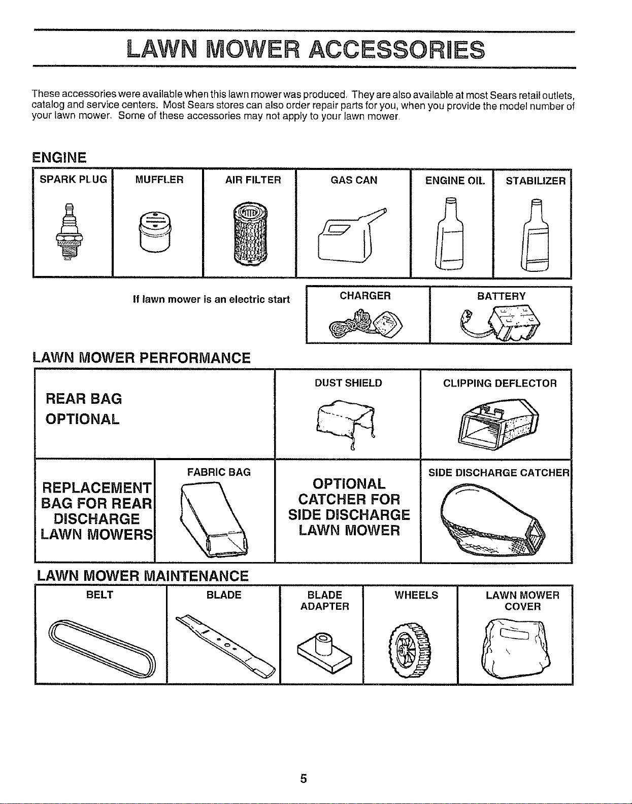
These accessories were available when this lawn mower was producedr They are also available at most Sears retail outlets,
catalog and service centers. Most Sears stores can also order repair parts for you, when you provide the model number of
your lawn mower. Some of these accessories may not apply to your lawn mower
ENGINE
SPARK PLUG MUFFLER
0
AIR FILTER
GAS CAN ENGINE OIL STABILIZER
If lawn mower is an electric start
LAWN MOWER PERFORMANCE
REAR BAG
OPTIONAL
REPLACEMENT
BAG FOR REAR
DISCHARGE
LAWN MOWERS
FABRIC BAG
I
q
I CHARGER I BATTERY
DUST SHIELD
OPTIONAL
CATCHER FOR
SIDE DISCHARGE
LAWN MOWER
CLIPPING DEFLECTOR
SIDE DISCHARGE CATCHER
LAWN MOWER MAINTENANCE
5
ASSEMBLY
Read these instructions and this manual in its entirety
before you attempt to assemble or operate your new lawn
mower. Your new lawn mower has been assembled at the
factory with the exception of those parts left unassembled
for shipping purposes. To ensure safe and proper opera-
tion of your lawn mower', all parts and hardware you
assemble must be tightened securely Use the correct
tools as necessary to ensure proper tightness All parts
such as nuts, washers, bolts, etc. necessary to complete
the assembly have been placed in the parts bag.
TO REMOVE LAWN MOWER FROM
CARTON
Remove loose parts included with mower.
Cut down two end corners of carton and lay end panel
down flat
• Remove all packing materials except padding be-
tween upper and lower handle and padding holding
operator presence control bar to upper handle.
• Roll lawn mower out of carton and check carton
thoroughly for additional loose parts.
HOW TO SET UP YOUR LAWN
MOWER
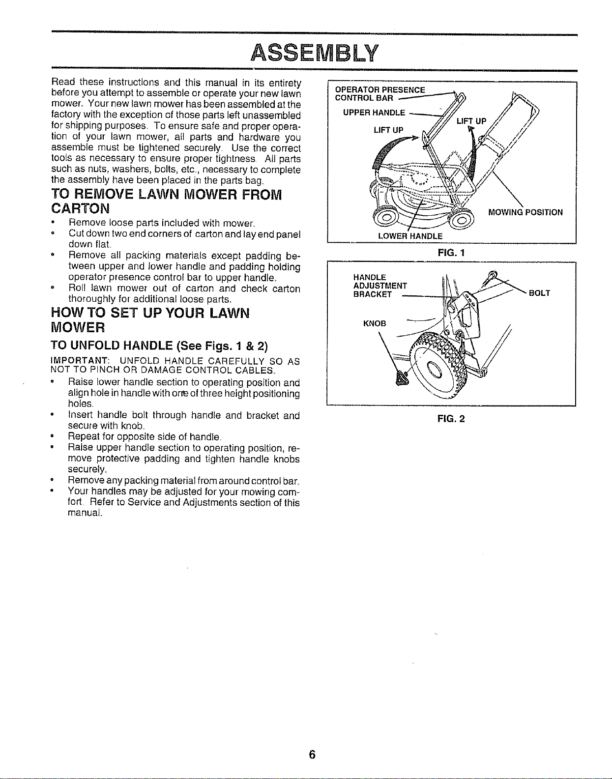
TO UNFOLD HANDLE (See Figs. 1 & 2)
IMPORTANT: UNFOLD HANDLE CAREFULLY SO AS
NOT TO PINCH OR DAMAGE CONTROL CABLES_
• Raise lower handle section to operating position and
align hole in handle with or'reof three height positioning
holes.
o Insert handle bolt through handle and bracket and
secure with knob
Repeat for opposite side of handle.
Raise upper handle section to operating position, re-
move protective padding and tighten handle knobs
securely.
° Remove any packing material from around control bar.
. Your handles may be adjusted for' your' mowing com=
fort Refer to Service and Adjustments section of this
manual.
OPERATOR PRESENCE
CONTROLBAR
UPPER HANDLE
LIFT UP
LOWER HANDLE
FIG. 1
HANDLE
ADJUSTMENT
BRACKET
MOWING POSITION
KNOB
FIG. 2
6
ASSEMBLY
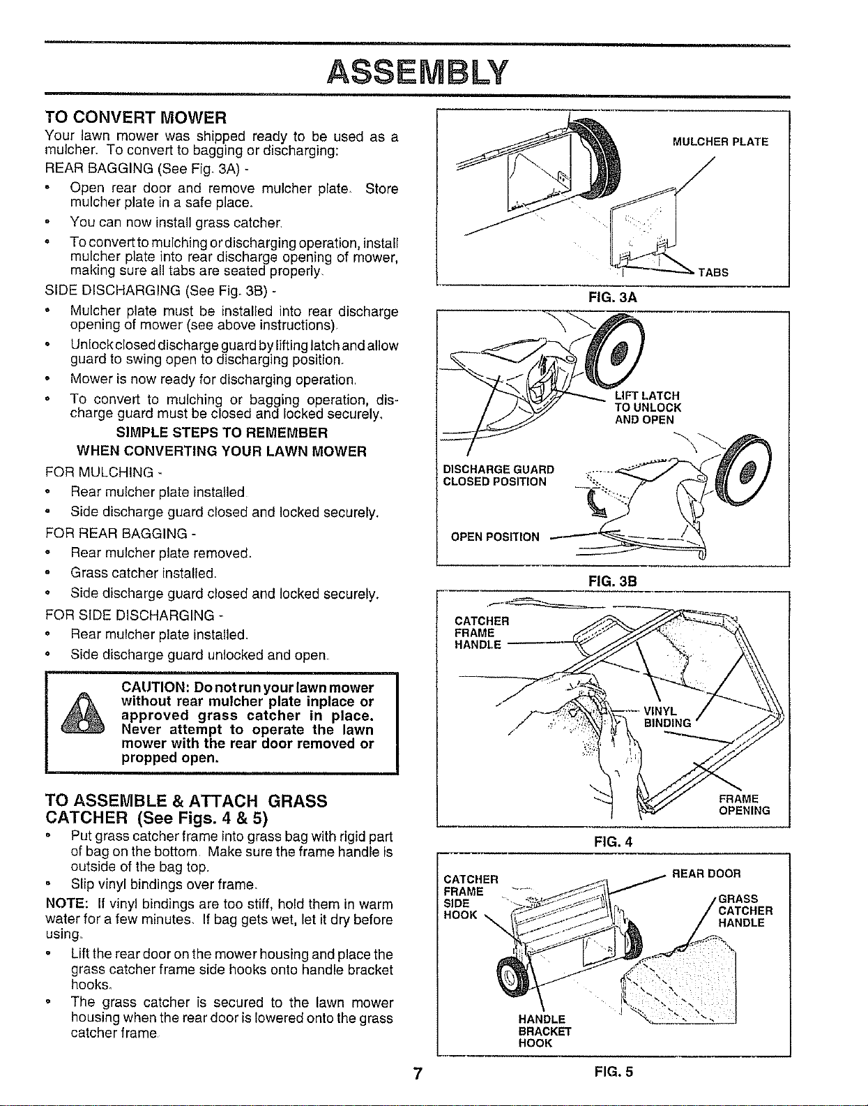
TO CONVERT MOWER
Your lawn mower was shipped ready to be used as a
mulcher. To convert to bagging or discharging:
REAR BAGGING (See Fig_3A) -
= Open rear door and remove mulcher plate. Store
mulcher plate in a safe place.
You can now install grass catcher
To convert to mulching or discharging operation, install
mulcher plate into rear discharge opening of mower,
making sure all tabs are seated properly.
SIDE DISCHARGING (See Fig. 3B) -
Mulcher plate must be installed into rear discharge
opening of mower (see above instructions)
Unlock closed discharge guard by lifting latch and allow
guard to swing open to discharging position.
Mower is now ready for discharging operation
To convert to mulching or bagging operation, dis-
charge guard must be closed and locked securely_
SIMPLE STEPS TO REMEMBER
WHEN CONVERTING YOUR LAWN MOWER
FOR MULCHING
• Rear mulcher plate installed
Side discharge guard closed and locked securely.
FOR REAR BAGGING -
• Rear mulcher plate removed.
o Grass catcher installed
Side discharge guard closed and locked securely.
FOR SIDE DISCHARGING
• Rear mulcher plate installed.
= Side discharge guard unlocked and open,
CAUTION: Do not run your lawn mower
without rear mulcher plate inplace or
approved grass catcher in place.
Never attempt to operate the lawn
mower with the rear door removed or
propped open.
TO ASSEMBLE & ATTACH GRASS
CATCHER (See Figs. 4 & 5)
• Put grass catcher frame into grass bag with rigid part
of bag on the bottom Make sure the frame handle is
outside of the bag top.
° Slip vinyl bindings over frame.
NOTE: If vinyl bindings are too stiff, hold them in warm
water for a few minutes, If bag gets wet, let itdry before
using_
Lift the rear door on the mower housing and place the
grass catcher frame side hooks onto handle bracket
hooks.
The grass catcher is secured to the lawn mower
housing when the rear door is lowered onto the grass
catcher frame
MULCHER PLATE
FIG. 3A
/ _./_ LIFT LATCH
/ _ _'/ TO UNLOCK
ANDOPEN
DISCHARGE GUARD
CLOSED POSITION %.
OPEN POSITION
FIG. 3B
CATCHER
FRAME
HANDLE
CATCHER
FRAME
SIDE
HOOK_
FRAME
OPENING
FIG. 4
REAR DOOR
rGRASS
HANDLE
HANDLE
BRACKET
HOOK
7 FIG. 5
OPERATION
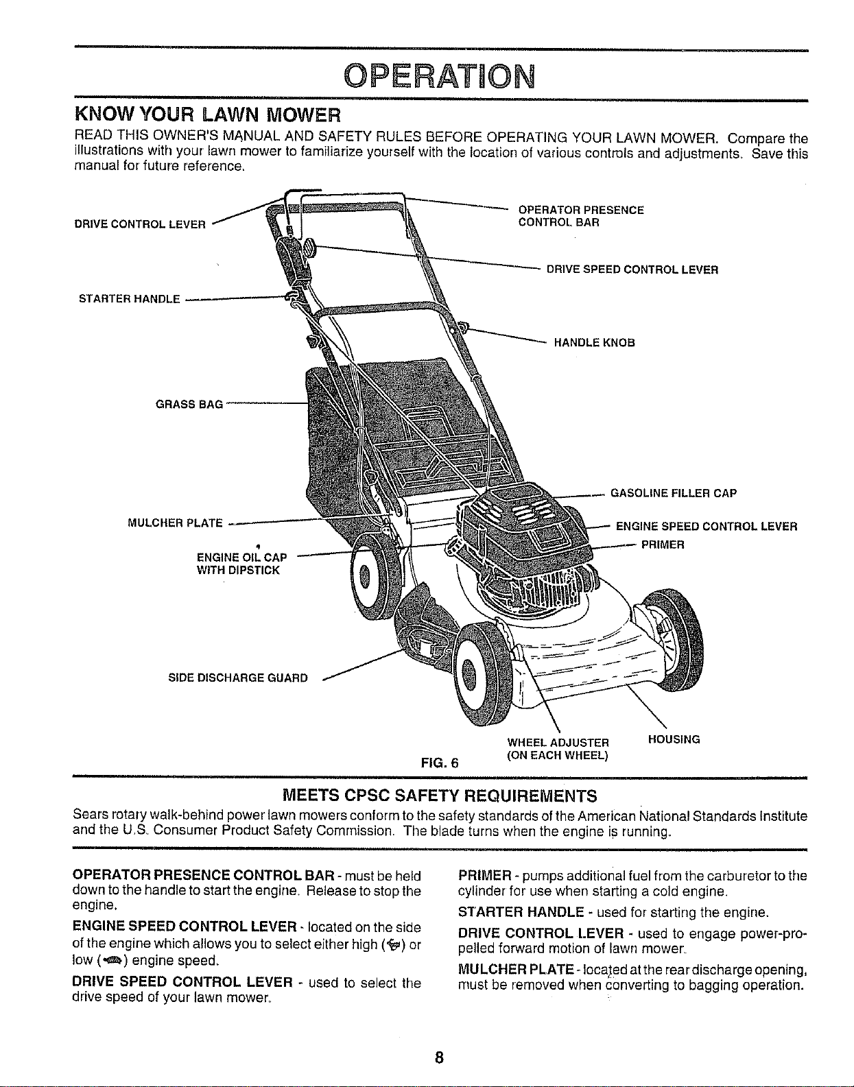
KNOW YOUR LAWN MOWER
READ THIS OWNER'S MANUAL AND SAFETY RULES BEFORE OPERATING YOUR LAWN MOWER. Compare the
illustrations with your lawn mower to familiarize yourself with the location of various controls and adjustments_ Save this
manual for future reference=
DRIVE CONTROL LEVER
OPERATOR PRESENCE
CONTROL BAR
STARTER HANDLE
DRIVE SPEED CONTROL LEVER
HANDLE KNOB
GRASS BAG
MULCHER PLATE
4
ENGINE OIL CAP
WITH DIPSTICK
GASOLINE FILLER CAP
NTROL LEVER
PRIMER
SIDE DISCHARGE GUARD
FIG. 6
WHEEL ADJUSTER
(ON EACH WHEEL)
HOUSING
MEETS CPSC SAFETY REQUIREMENTS
Sears rotary walk-behind power lawn mowers conform to the safety standards of the American National Standards Institute
and the U,S_ Consumer Product Safety Commission The blade turns when the engine iS running.
OPERATOR PRESENCE CONTROL BAR - must be held
down to the handle to start the engine. Release to stop the
engine.
ENGINE SPEED CONTROL LEVER- located ORthe side
of the engine which allows you to select either high ('_) or
low (.¢_) engine speed.
DRIVE SPEED CONTROL LEVER - used to select the
drive speed of your lawn mower.
PRIMER - pumps additional fuel from the carburetor to the
cylinder for use when starting a cold engine.
STARTER HANDLE - used for starting the engine.
DRIVE CONTROL [.EVER - used to engage power-pro-
pelled forward motion of lawn mower_
MULCHER PLATE-located atthe reardischarge opening,
must be removed when converting to bagging operation.
8
OPERATION
HOW TO USE YOUR LAWN MOWER ENGINESPEED
CONTROL LEVER
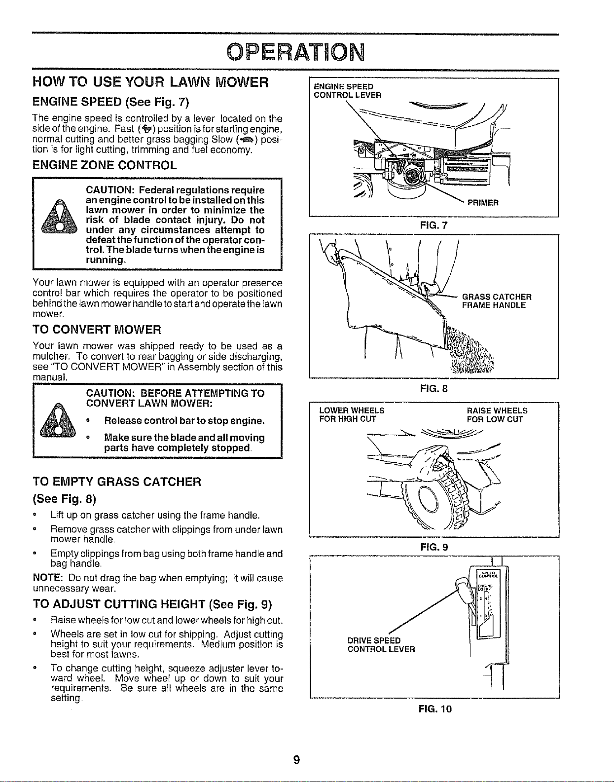
ENGINE SPEED (See Fig. 7)
The engine speed is controlled by a lever located on the
side of the engine_ Fast ('_) position is for starting engine,
normal cutting and better grass bagging Slow (._) posi_
tion is for light cutting, trimming and fuel economy.
ENGINE ZONE CONTROL
&
CAUTION: Federal regulations require
an engine control to be installed on this
lawn mower in order to minimize the
risk of blade contact injury. Do not
under any circumstances attempt to
defeat the function of the operator con-
trol. The blade turns when the engine is
running,
Your lawn mower is equipped with an operator presence
control bar which requires the operator to be positioned
behind the lawn mower handle to start and operate the lawn
mower,
TO CONVERT MOWER
Your lawn mower was shipped ready to be used as a
mulcher. To convert to rear bagging or side discharging,
see 'q-O CONVERT MOWER" in Assembly section of this
manual.
CAUTION: BEFORE ATTEMPTING TO
CONVERT LAWN MOWER:
° Release control bar to stop engine.
o Make sure the blade and all moving
parts have completely stopped,
TO EMPTY GRASS CATCHER
(See Fig. 8)
= Lift up on grass catcher using the frame handle.
. Remove grass catcher with clippings from under lawn
mower handle
= Empty clippings from bag using both frame handle and
bag handle
NOTE: Do not drag the bag when emptying; it will cause
unnecessary wear.
TO ADJUST CUTTING HEIGHT (See Fig. 9)
• Raise wheels for low cut and lower wheels for high cut.
• Wheels are set in low cut for shipping. Adjust cutting
height to suit your requirements, Medium position is
best for most lawns_
To change cutting height, squeeze adjuster lever to-
ward wheel Move wheel up or down to suit your
requirements. Be sure all wheels are in the same
setting,
PRIMER
FIG. 7
GRASS CATCHER
FRAME HANDLE
FIG. 8
LOWER WHEELS
FOR HIGH CUT
RAISE WHEELS
FOR LOW CUT
FIG, 9
DRIVE SPEED
CONTROL LEVER
FIG. '10
9
OPERATION
GROUND DRIVE FOUR SPEEDS
(See Fig. 10)
Your lawn mower provides four (4) speeds to letyou select
the speed that suits you best
The drive speed control lever can be changed while
you are mowing.
Speeds 1 and 2 are found when the engine speed
control (red) lever is in low (._=_)position.
Speeds 1 and 2 are for slower, light grass cutting,
trimming and quiet operation_
Speeds 3 and 4 are found when the engine speed
control (red) lever is in high (_) position.
Speed 3 is for slow, heavy/thick grass cutting or
trimming.
Speed 4 is for normal cutting and bagging arid for
ground transport.
IMPORTANT: DO NOT ATTEMPT TO SHIFT SPEEDS
WITH THE DRIVE BAR ENGAGED UNLESS THE ENGINE
IS RUNNING
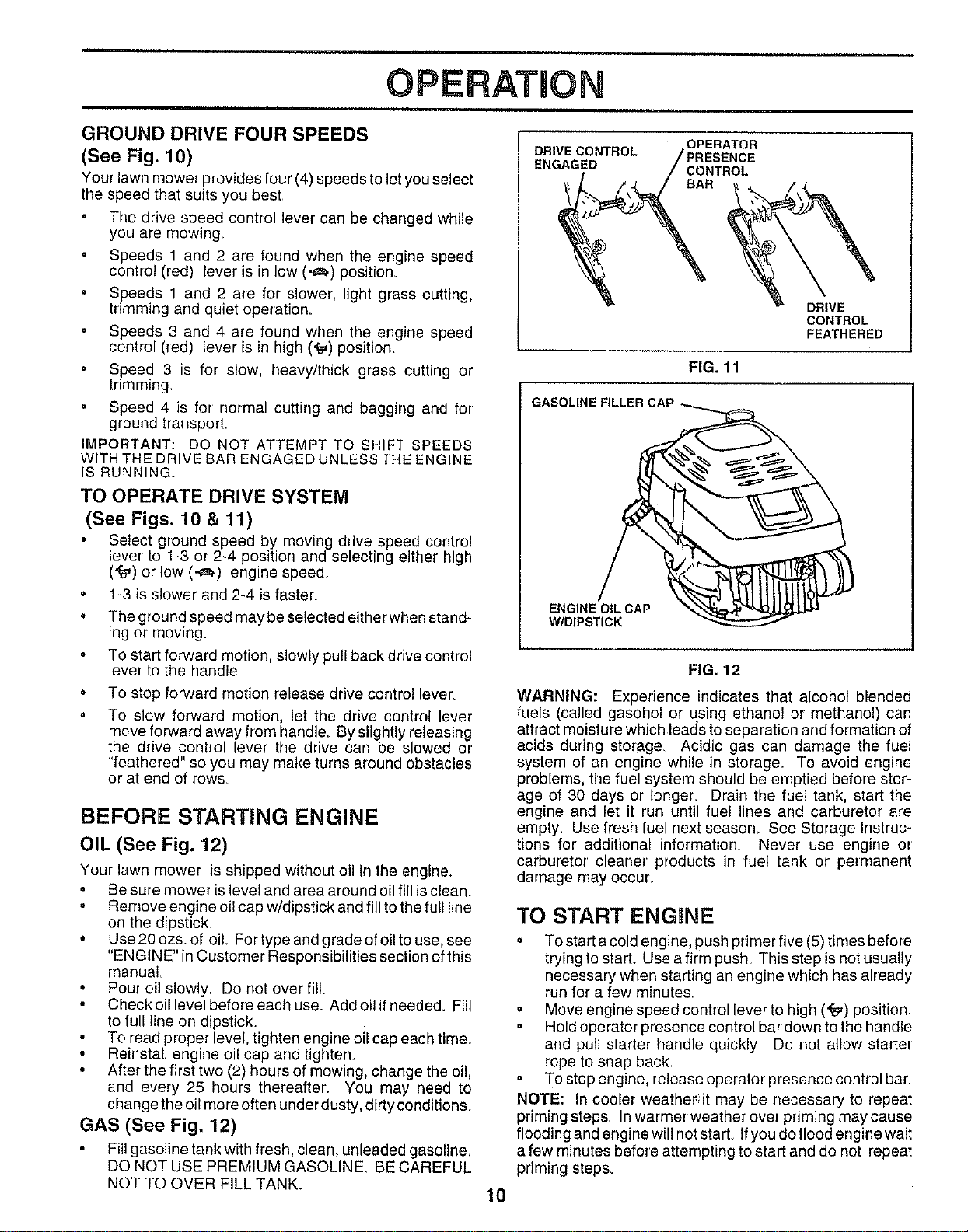
TO OPERATE DRIVE SYSTEM
(See Figs. 10 & 11)
Select ground speed by moving drive speed control
lever to 1-3 or 2-4 position and selecting either high
('_) or low (,,=_) engine speed,
• 1-3 is slower and 2_4 isfaster,
The ground speed maybe selected either when stand-
ing or rnoving
To start forward motion, slowly pul! back drive control
lever' to the handle
To stop forward motion release drive corrtrol lever
To slow forward motion, let the drive control lever
move forward away from handle. By slightly releasing
the drive control lever the drive can be slowed or
"feathered" so you may make turns around obstacles
or' at end of rows_
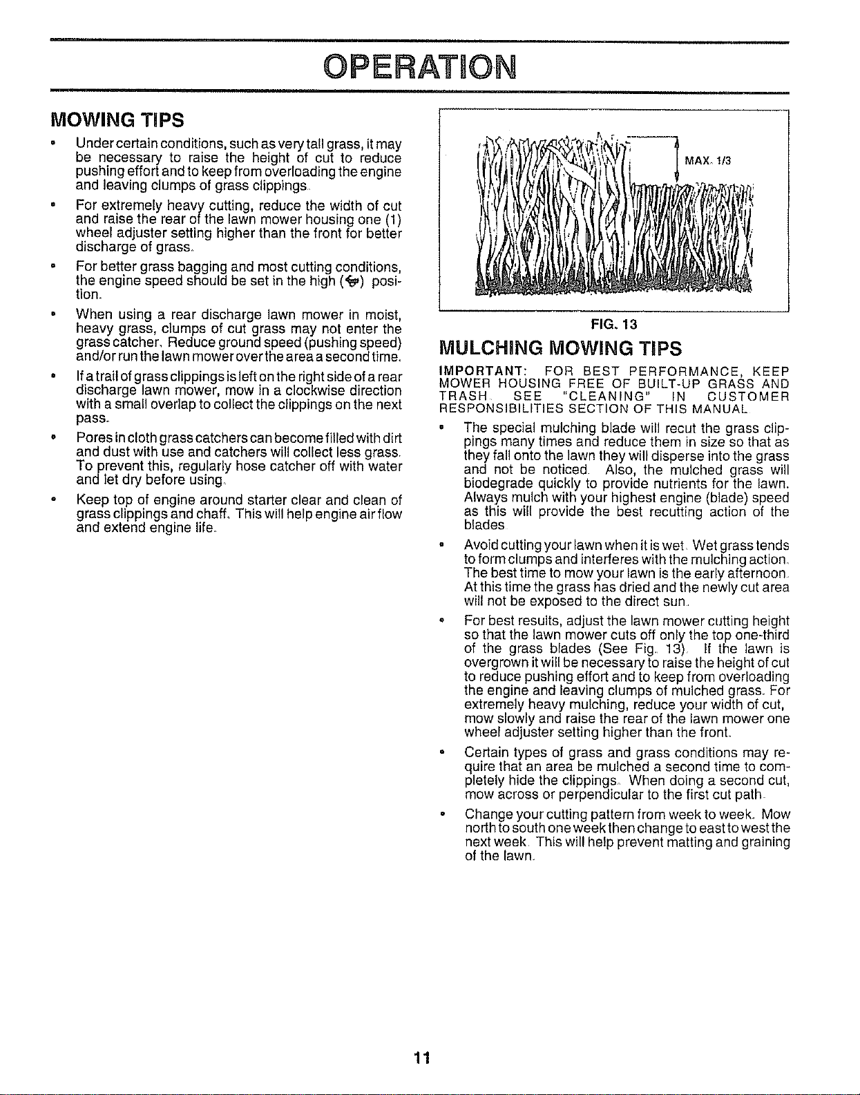
BEFORE STARTING ENGINE
OIL (See Fig. 12)
Your lawn mower is shipped without oil in the engine.
• Be sure mower is level and area around oil fill is clean.
° Remove engine oil cap w/dipstick and fill to the full line
on the dipstick.
• Use20ozs.of oil. For typeandgradeofoilto use, see
"ENGINE" in Customer Responsibilities section of this
manual.
° Pour oil slowly. Do riot over' fill
. Check oil level before each use. Add oll if needed. Fill
to full line on dipstick.
To read proper level, tighten engine oil cap each tirne.
o Reinstall engine oil cap and tighten.
o After the first two (2) hours of mowing, change the oil,
and every 25 hours thereafter. You may need to
change the oil more often underdusty, dirty conditions.
GAS (See Fig, 12)
Fill gasoline tank with fresh, clean, unleaded gasoline,
DO NOT USE PREMIUM GASOLINE, BE CAREFUL
NOT TO OVER FILL TANK.
DRIVE CONTROL OPERATOR
ENGAGED CONTROL
BAR
FIG. 11
GASOLINE
DRIVE
CONTROL
FEATHERED
ENGINE OIL CAP
W/DIPSTICK
10
FIG. 12
WARNING: Experience indicates that alcohol blended
fuels (called gasohol or L_singethanol or methanol) can
attract moisture which leads to separation and formation of
acids during storage. Acidic gas can damage the fuel
system of an engine while in storage. To avoid engine
problems, the fuel system should be emptied before stor-
age of 30 days or longer,. Drain the fuel tank, start the
engine and let it run until fuel lines and carburetor are
empty. Use fresh fuel next season See Storage Instruc-
tions for additional information Never use engine or
carburetor cleaner products in fuel tank or permanent
damage may occur.
TO START ENGINE
o To start a cold engine, push primer five (5) times before
trying to start. Use a firm push. This step is not usually
necessary when starting an engine which has already
run for a few minutes.
° Move engine speed control lever to high ('_) position,
Hold operator presence control bar' down to the handle
and pull starter handle quickly Do not allow starter
rope to snap back,
To stop engine, release operator presence control bar'.
NOTE: In cooler weather it may be necessary to repeat
priming steps Inwarmerweatherover priming maycause
flooding and engine will not start. If you do flood engine wait
a few minutes before attempting to start and do not repeat
priming steps.
OPERATION
MOWING TIPS
• Undercertain conditions, such as very tall grass, it may
be necessary to raise the height of cut to reduce
pushing effort and to keep from overloading the engine
and leaving clumps of grass clippings
• For extremely heavy cutting, reduce the width of cut
and raise the rear of the lawn mower housing one (1)
wheel adjuster setting higher than the front for better
discharge of grass.
• For better grass bagging and most cutting conditions,
the engine speed should be set in the high ('_) posi-
tion.
• When using a rear discharge lawn mower in moist,
heavy grass, clumps of cut grass may not enter the
grass catcher, Reduce ground speed (pushing speed)
and/or run the lawn mower over the area a second time,
• If atraitof grassclippingsisleft onthe right side of a rear
discharge lawn mower, mow in a clockwise direction
with a small overlap to collect the clippings on the next
pass.
• Pores in cloth grass catchers can become filled with dirt
and dust with use and catchers will collect less grass.
Toprevent this, regularly hose catcher off with water
andlet dry before using.
• Keep top of engine around starter clear and clean of
grass clippings and chaff_ This will help engine air flow
and extend engine life.
MAX. 1/3
FIG. 13
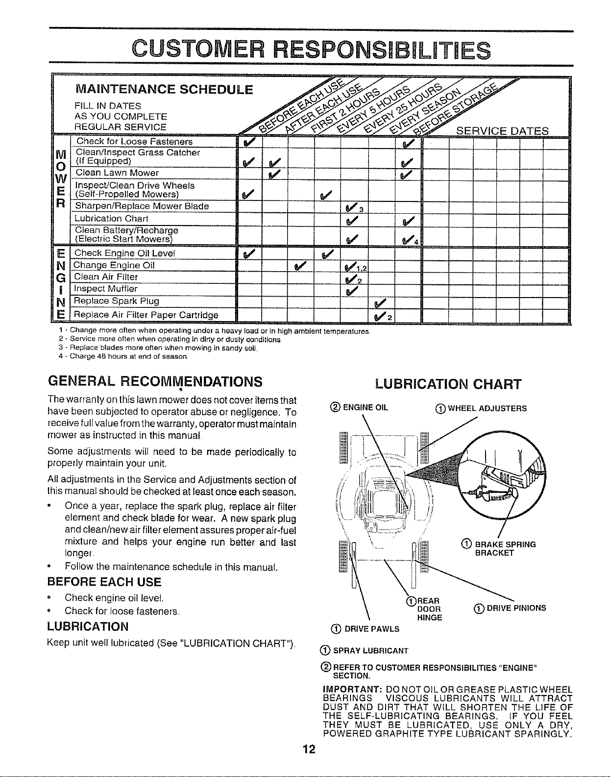
MULCHING MOWING TIPS
IMPORTANT: FOR BEST PERFORMANCE, KEEP
MOWER HOUSING FREE OF BUILT-UP GRASS AND
TRASH SEE "CLEANING" IN CUSTOMER
RESPONSIBILITIES SECTION OF THIS MANUAL
The special mulching blade will recur the grass clip-
pings many times and reduce them in size so that as
they fall onto the lawn they will disperse into the grass
and not be noticed Also, the mulched grass will
biodegrade quickly to provide nutrients for the lawn.
Always mulch with your highest engine (blade) speed
as this will provide the best recutting action of the
blades
Avoid cutting your lawn when it is wet Wet grass tends
to form clumps and interferes with the mulching action.
The best time to mow your lawn is the early afternoon
At this time the grass has dried and the newly cut area
will not be exposed to the direct sun
° For best results, adjust the lawn mower cutting height
so that the lawn mower cuts off only the top one-third
of the grass blades (See Fig. 13) If the lawn is
overgrown it will be necessary to raise the height of cut
to reduce pushing effort and to keep from overloading
the engine and leaving clumps of mulched grass. For
extremely heavy mulching, reduce your width of cut,
mow slowly and raise the rear of the lawn mower one
wheel adjuster setting higher than the front.
• Certain types of grass and grass conditions may re-
quire that an area be mulched a second time to com-
pletely hide the clippings. When doing a second cut,
mow across or perpendicular to the first cut path
° Change your cutting pattern from week to week. Mow
north to south one week then change to east to west the
next week This will help prevent matting and graining
of the lawn
11
CUSTOMER RESPONSJ ILITIES
MAINTENANCE SCHEDULE __ _ _ _ _ _
REGULARSERV,CE
Check for Loose Fasteners _
OO Clean/Inspect Grass Catcher(If Equipped) _ _ 6/
Clean Lawn Mower _
Inspect/Clean Drive Wheels
(Self-Propelled Mowers) _ 6#4
R Sharpen/Replace Mower Blade _a
Lubrication Chart _
Clean Battery/Recharge
(Electric Start Mowers) _ _4
E Check Engine Oil Level _
N Change Engine Oi! _ 1_1,2
G clean Air Filter _2 _____
Inspect Muffler !##
N Replace Spark Plug
E Replace Air Filter Paper Cartridge _2
1 - Change more often when operating under a heavy load or In high ambient temperatures
2 - Service more often when operating in dirty or dusly conditions
3 - Replace blades more often when mowing in sandy soil
4 * Charge 48 hours at end of season
GENERAL RECOIVIMENDATIONS
The warranty on this lawn mower does not cover items that
have been subjected to operator' abuse or negligence, To
receive full value from the warranty, operator must maintain
mower as instructed in this manual
Some adjustments will need to be made periodically to
properly maintain your unit.
All adjustments in the Service and Adjustments section of
this manual should be checked at least once each season,
Once a year, replace the spark plug, replace air filter
element and check blade for wear. A new spark plug
and clean/new air filter element assures proper air-fuel
mixture and helps your engine run better and last
longer
Follow the maintenance schedule in this manual.
BEFORE EACH USE
Check engine oil level
° Check for loose fasteners
LUBRICATION
Keep unit well lubricated (See "LUBRICATION CHART")
LUBRiCATiON CHART
(_) ENGINE OIL (_) WHEEL ADJUSTERS
(_ BRAKE SPRING
BRACKET
12
(_)REAR
DOOR
HINGE
(_)DRIVEPAWLS
(_ DRIVE PINIONS
(_) SPRAY LUBRICANT
(_) REFER TO CUSTOMER RESPONSIBILITIES "ENGINE"
SECTION.
IMPORTANT: DO NOT OIL OR GREASE PLASTIC WHEEL
BEARINGS VISCOUS LUBRICANTS WILL ATTRACT
DUST AND DIRT THAT WILL SHORTEN THE LIFE OF
THE SELF-LUBRICATING BEARINGS. IF YOU FEEL
THEY MUST BE LUBRICATED, USE ONLY A DRY,
POWERED GRAPHITE TYPE LUBRICANT SPARINGLY.
CUSTOMER RESPONSmBILITmES
LAWN MOWER
Always observe safety rules when performing any mainte-
nance,
TIRES
= Keep tires free of gasoline, oil, or insect control chemi-
cals which can harm rubber.
• Avoid stumps, stones, deep ruts, sharp objects and
other hazards that may cause tire damage.
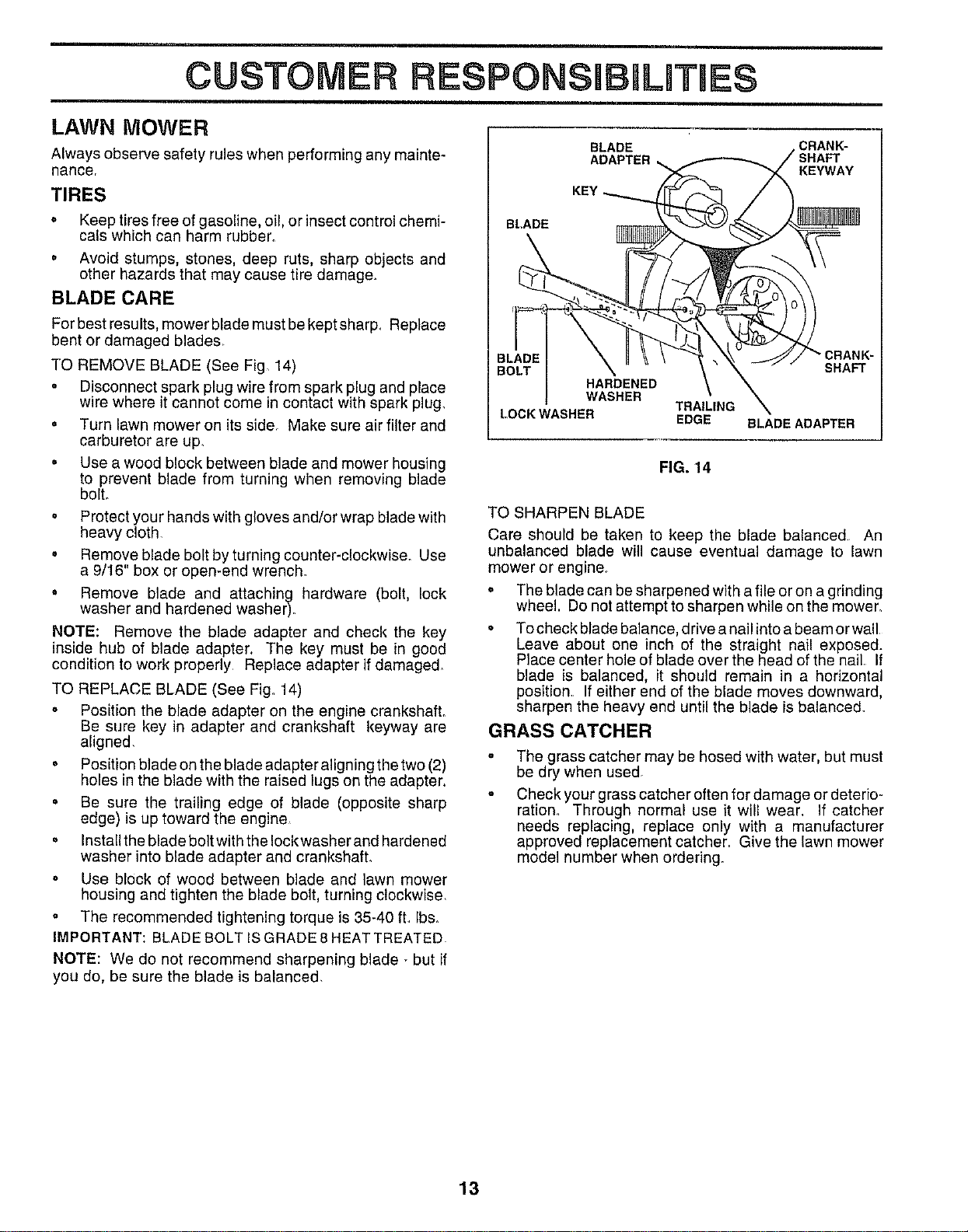
BLADE CARE
For best results, mower blade must be kept sharp_ Replace
bent or damaged blades_
TO REMOVE BLADE (See Fig 14)
o Disconnect spark plug wire from spark plug and place
wire where it cannot come in contact with spark plug,
o Turn lawn mower on its side_ Make sure air filter and
carburetor are up.
o Use a wood block between blade and mower housing
to prevent blade from turning when removing blade
bolt.
° Protect your hands with gloves and/or wrap blade with
heavy cloth
• Remove blade bolt by turning counter-clockwise. Use
a 9/16" box or open-end wrench.
• Remove blade and attaching hardware (bolt, lock
washer and hardened washer)_
NOTE: Remove the blade adapter and check the key
inside hub of blade adapter. The key must be in good
condition to work properly Replace adapter if damaged.
TO REPLACE BLADE (See Fig, 14)
= Position the blade adapter on the engine crankshafL
Be sure key in adapter and crankshaft keyway are
aligned,
• Position blade on the blade adapter aligning the two (2)
holes in the blade with the raised lugs on the adapter.
• Be sure the trailing edge of blade (opposite sharp
edge) is up toward the engine
• Install the blade bolt with the Iockwasher and hardened
washer into blade adapter and crankshaft,
o Use block of wood between blade and lawn mower
housing and tighten the blade bolt, turning clockwise,
= The recommended tightening torque is 35-40 ft,, Ibs,
IMPORTANT: BLADE BOLT ISGRADE 8 HEAT TREATED
NOTE: We do not recommend sharpening blade - but if
you do, be sure the blade is balanced,
BLADE , CRANK-
ADAPTER ,,.. _ 7 SHAFT
KEYWAY
BLADE \ II \\ \ _,_ ._ _// "CRANK-
BOLT _ " _ ' X _ SHAFT
HARDENED \ \
WASHER TRAII_ING
LOCK WASHER EDGE BLADE ADAPTER
FIG. 14
TO SHARPEN BLADE
Care should be taken to keep the blade balanced, An
unbalanced blade will cause eventual damage to lawn
mower or engine,
= The blade can be sharpened with a file or on a grinding
wheel. Do not attempt to sharpen while on the mower,
° To check blade balance, drive a nail into a beam or wall
Leave about one inch of the straight nai! exposed.
Place center hole of blade over the head of the nail If
blade is balanced, it should remain in a horizontal
position, If either end of the blade moves downward.
sharpen the heavy end until the blade is balanced,
GRASS CATCHER
°
°
The grass catcher may be hosed with water, but must
be dry when used.
Check your grass catcher often for damage or deterio-
ration. Through normal use it will wear. If catcher
needs replacing, replace only with a manufacturer
approved replacement catcher. Give the lawn mower
model number when ordering.
13
CUSTOMER RESPONSiBiLiTiES
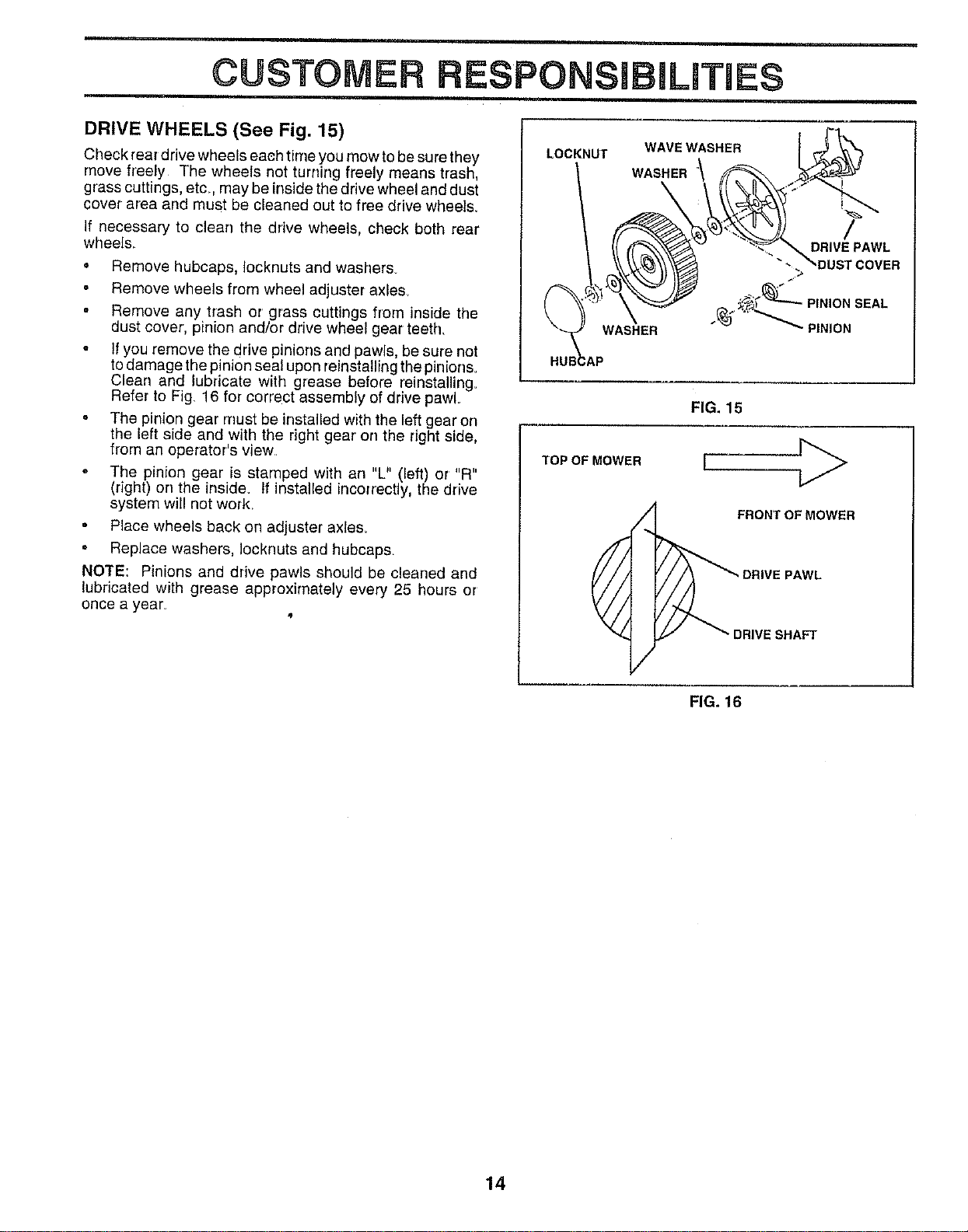
DRIVE WHEELS (See Fig. 15)
Check rear drive wheels each time you mow to be sure they
move freely The wheels net turning freely means trash,
grass cuttings, etc. may be inside the drive wheel and dust
cover area and must be cleaned out to free drive wheels.
If necessary to clear] the drive wheels, check both rear
wheels
. Remove hubcaps. Iocknuts and washers
Remove wheels from wheel adjuster axle&
Remove any trash or grass cuttings from inside the
dust cover', pinion and/or drive wheel gear teeth,
. If you remove the drive pinions and pawls, be sure not
to damage the pinion seal upon reinstallingthe pinions.
Clean and lubricate with grease before reinstalling.
Refer to Fig. 16 for correct assembly of drive pawL
The pit,ion gear must be installed with the left gear on
the left side and with the right gear on the right side,
from an operator's view.
• The pinion gear is stamped with an "L" (left) or "R"
(right) on the inside, tf installed incorrectly, the drive
system will not work.
Place wheels back on adjuster axle&
• Replace washers, Iocknuts and hubcaps.
NOTE: Pinions and drive pawls should be cleaned and
lubricated with grease approximately every 25 hours or
once a year_
LOCKNUT WAVE WASHER I _'_
\ w.S.ERk
FIG. 15
TOP OF MOWER
FRONT OF MOWER
DRIVE PAWL
DRIVE SHAFT
FIG. 16
14
CUSTOMER RESPONSIBmLmTmES
ENGINE
LUBRICATION
Use only high quality detergent oil rated with API service
classification SG_ Select the oil's SAE viscosity grade
according to your expected operating temperature,
SAE VISCOSITY GRADES
"20 = 0 ° 30" 32 ° 40° 60 _ 80' 100"
TEMPERATURE RANGE ANTICIPATED BEFORE NEXT O_LCHANGE
NOTE: Although multi-viscosity oils (5W30, 10W30 etc.)
improve starting in cold weather, these multi-viscosity oils
will result in increased oil consumption when used above
32°F, Check your engine oil level more frequently to avoid
possible engine damage from running low on oil
Change the oil after the first two hours of operation and
every 25 hours thereafter or at least once a year ifthe lawn
mower is not used for 25 hours in one year_
Check the crankcase oil level before starting the engine
and after each five (5) hours of continuous use Tighten oil
plug securely each time you check the oil level
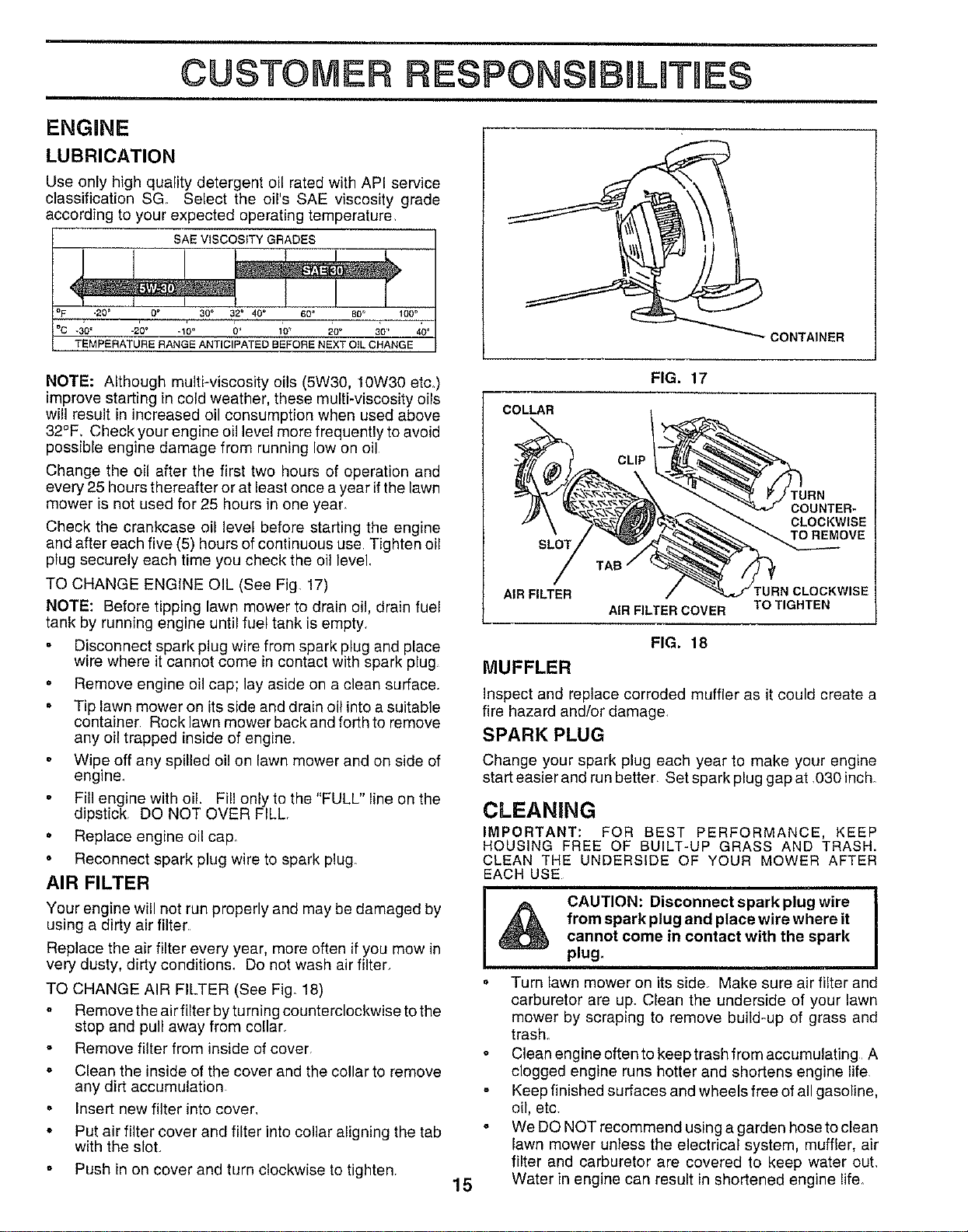
TO CHANGE ENGINE OIL (See Fig. 17)
NOTE: Before tipping lawn mower to drain oil, drain fuel
tank by running engine until fuel tank is empty,
Disconnect spark plug wire from spark plug and place
wire where it cannot come in contact with spark plug
= Remove engine oil cap; lay aside on a clean surface.
= Tip lawn mower on its side and drain oil into a suitable
container Rocklawn mowerbackandforthto remove
any oil trapped inside of engine
° Wipe off any spilled oi! on lawn mower and on side of
engine.
° Fill engine with oil. Fill only to the "FULL" line on the
dipstick, DO NOT OVER FILL.
• Replace engine oil cap
• Reconnect spark plug wire to spark plug.
AIR FILTER
Your engine will not run properly and may be damaged by
using a dirty air filter,
Replace the air filter every year, more often if you mow in
very dusty, dirty conditions_ Do not wash air filter,
TO CHANGE AIR FILTER (See Fig. 18)
" Remove the air filter by turning counterclockwise to the
stop and pull away from collar.
Remove filter from inside of cover.
= Clean the inside of the cover and the collar to remove
any dirt accumulation
. Insert new filter into cover.
* Put air filter cover and filter into collar aligning the tab
with the sloL
, Push in on cover and turn clockwise to tighten.
I
CONTAINER
FIG. 17
COLLAR
SLOT
CLIP
TURN
COUNTER-
CLOCKWISE
15
AIR FILTER TURN CLOCKWISE
AIR FILTER COVER TO TIGHTEN
FIG. 18
MUFFLER
Inspect and replace corroded muffler as it could create a
fire hazard and/or damage,
SPARK PLUG
Change your spark plug each year to make your engine
start easier and run better. Set spark plug gap at .030 inch_
CLEANING
IMPORTANT: FOR BEST PERFORMANCE, KEEP
HOUSING FREE OF BUILT-UP GRASS AND TRASH.
CLEAN THE UNDERSIDE OF YOUR MOWER AFTER
EACH USE
I & CAUTION: Disconnect spark plug wire
from spark plug and place wire where it
cannot come in contact with the spark
plug.
° Turn lawn mower on its side. Make sure air filter and
carburetor are up. Clean the underside of your lawn
mower by scraping to remove build-up of grass and
trash.
Clean engine often to keep trash from accumulating A
clogged engine runs hotter and shortens engine life
Keep finished surfaces and wheels free of all gasoline,
oil, etc,
We DO NOT recommend using a garden hose to clean
lawn mower unless the electrical system, muffler, air
filter and carburetor are covered to keep water ouL
Water in engine can result in shortened engine life.
ERVmCE AOJUSTMENT$
I ,_ CAUTION: BEFORE PERFORMING ANY SERVICE OR ADJUSTMENTS: I
_k ° Release control bar and stop engine.
!
o Make sure the blade and all moving parts have completely stopped.
o Disconnect spark plug wire from spark plug and place where it cannot come in contact with plug.
LAWN MOWER
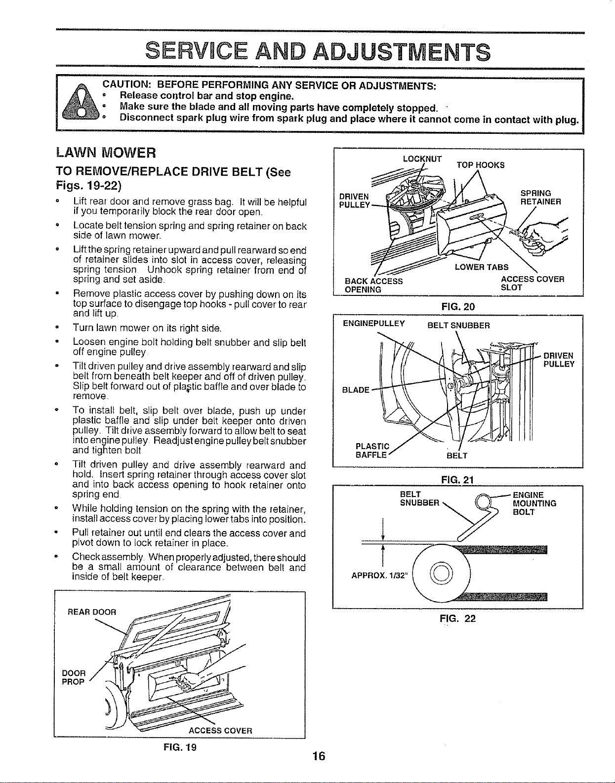
TO REIVIOVE/REPLACE DRIVE BELT (See
Figs. 19-22)
Lift rear door and remove grass bag It will be helpful
if you temporarily block the rear door open.
o Locate belt tension spring and spring retainer on back
side of lawn mower
o Liftthe spring retainer upward arrd pull rearward so end
of retainer' slides into slot in access cover, releasing
spring tension Unhook spring retainer from end of
spring and set aside
Remove plastic access cover by pushing down on its
top surface to disengage top hooks - pull cover to rear'
and lift up.
Turn lawn mower on its right side.
• Loosen engine bolt holding belt snubber and slip belt
off engine pulley
Tilt driven pulley and drive assembly rearward and slip
belt from beneath belt keeper and off of driven pulley.
Slip belt forward out of plastic baffle and over blade to
remove
To install belt, slip belt over blade, push up under
plastic baffle and slip under belt keeper onto driven
pulley Tilt drive assembly forward to allow belt to seat
into engine pulley Readjust engine pulley belt snubber
and tighten bolt
Tilt driven pulley and drive assembly rearward and
hold. Insert sprtng retainer' through access cover slot
and into back access opening to hook retainer onto
spring end
While holding tension on the spring with the retainer,
install access cover by placing !ower tabs into position.
Pull retainer out until end clears the access cover and
pivot down to lock retainer in place.
Check assembly. When properly adjusted, there should
be a small amount of clearance between belt and
inside of belt keeper
REAR DOOR
DOOR
PROP
ACCESS COVER
j
/...._-_
BACK ACCESS
OPENING
LOCKNUT
TOP HOOKS
LOWER TABS
ACCESS COVER
SLOT
FIG. 20
BELT SNUBBER
ENGINEPULLEY
BLADE _
PLASTIC/
BAFFLE" BELT
DRIVEN
PULLEY
FIG. 21
BELT _ ENGINE
SNUBBER _ _._)-L. MOUNTING
_ BOLT
APPROX_ 1/32' _.__
FIG. 22
FIG. 19
16
=ill
SERVICE AND ADJUSTMENTS
2-1/2"
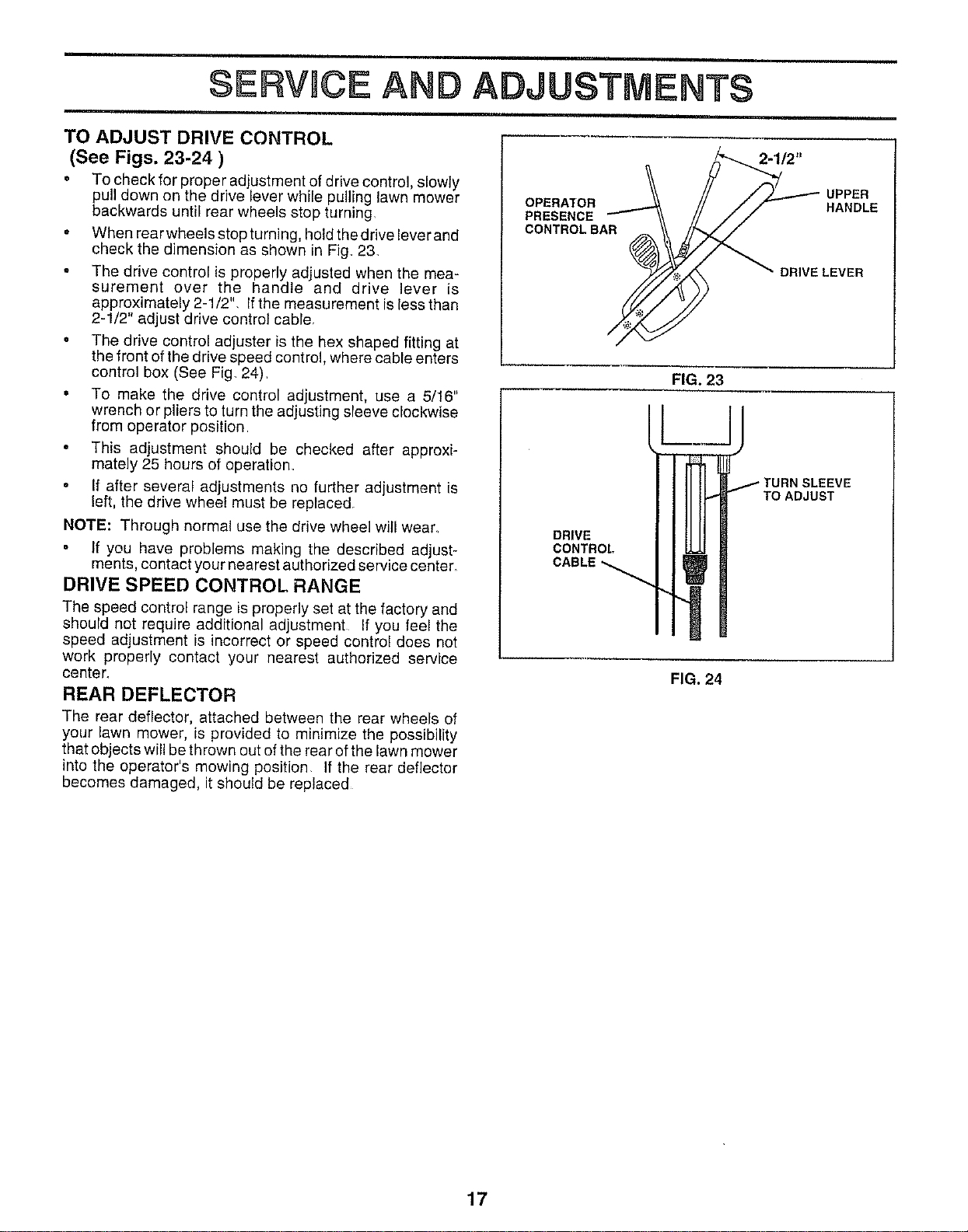
TO ADJUST DRIVE CONTROL
(See Figs. 23-24 )
• To check for proper adjustment of drive control, slowly
pull down on the drive lever while pulling lawn mower
backwards until rear wheels stop turning
° When rear wheels stop turning, hold the drive lever and
check the dimension as shown in Fig 23,
° The drive control is properly adjusted when the mea-
surement over the handle and drive lever is
approximately 2-1/2", Ifthe measurement is less than
2-1/2" adjust drive control cable,
o The drive control adjuster is the hex shaped fitting at
the front of the drive speed control, where cable enters
control box (See Fig 24)
° To make the drive control adjustment, use a 5/16"
wrench or pliers to turn the adjusting sleeve clockwise
from operator position
° This adjustment should be checked after approxi-
mately 25 hours of operation,
o If after several adjustments no further adjustment is
left, the drive wheel must be replaced,
NOTE: Through normal use the drive wheel will wear_
° If you have problems making the described adjust-
ments, contact your nearest authorized service center_
DRIVE SPEED CONTROL RANGE
The speed control range is properly set at the factory and
should not require additional adjustment If you feel the
speed adjustment is incorrect or speed control does not
work properly contact your nearest authorized service
center_
REAR DEFLECTOR
The rear deflector, attached between the rear wheels of
your lawn mower, is provided to minimize the possibility
that objects will be thrown out of the rear of the lawn mower
into the operator's mowing position If the rear deflector
becomes damaged, it should be replaced
OPERATOR
PRESENCE
CONTROL BAR
FIG. 23
DRIVE
CONTROL
CABLE
UPPER
HANDLE
FIG. 24
DRIVE LEVER
/TURN SLEEVE
TO ADJUST
17
SERVICE AND ADJUSTMENTS
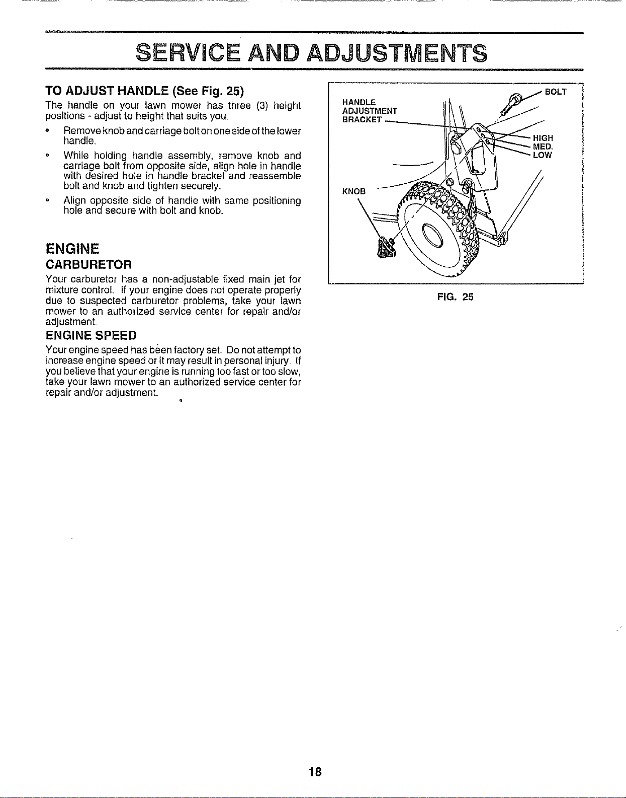
TO ADJUST HANDLE (See Fig. 25)
The handle on your lawn mower has three (3) height
positions - adjust to height that suits you.
o Removeknobandcarriageboltononesideofthelower
handle
o While holding handle assembly, remove knob and
cardage bolt from opposite side, align hole in handle
with desired hole in handle bracket and reassemble
bolt and knob and tighten securely=
° Align opposite side of handle with same positioning
hole and secure with bolt and knob
ENGINE
CARBURETOR
Your carburetor has a non-adjustable fixed main jet for
mixture control. If your engine does not operate properly
due to suspected carburetor problems, take your lawn
mower to an authorized service center for repair and/or
adjustment_
ENGINE SPEED
Your engine speed has been factory set Do not attempt to
increase engine speed or it may result inpersonal injury If
you believe that your engine is running too fast or too slow,
take your lawn mower to an authorized service center for
repair and/or adjustment.
HANDLE
ADJUSTMENT
KNOB
FIG. 25
HIGH
MED,
LOW
18
STORAGE
ENGUNE
Immediately prepare your lawn mower for storage at the
end of the season or if the unit will not be used for 30 days
or more,
LAWN MOWER
When lawn mower is to be stored for a period of time, clean
itthoroughly, remove al! dirt, grease, leaves, etc Store in
a clean, dry area.
• Clean entire lawn mower {See "CLEANING" in the
Customer Responsibilities section of this manual).
o Lubricate as shown in the Customer Responsibilities
section of this manual.
• Be sure that all nuts, bolts, screws, and pins are
securely fastened Inspect moving parts for damage,
breakage and wear. Replace if necessary_
o Touch up all rusted or chipped paint surfaces; sand
lightly before painting.
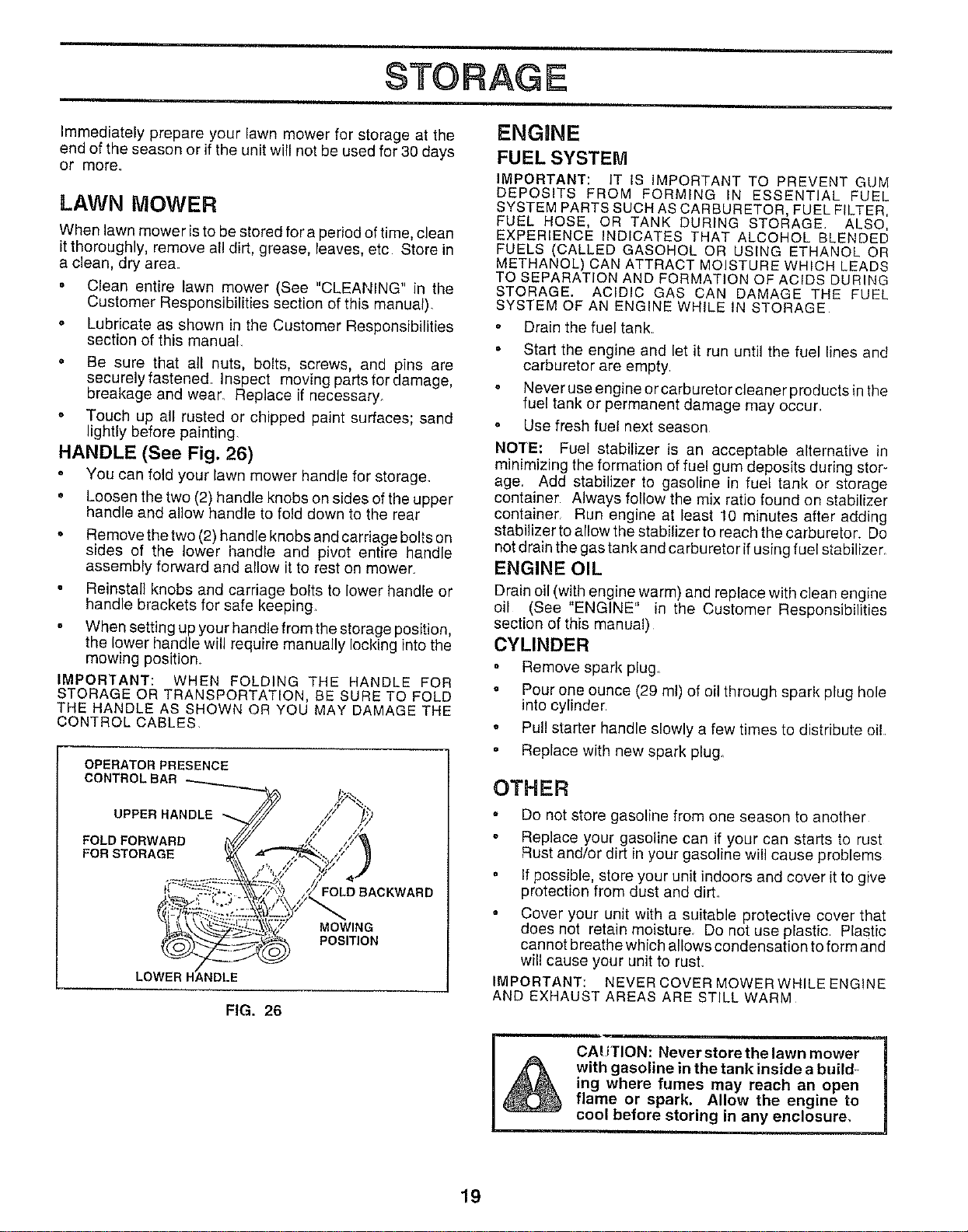
HANDLE (See Fig, 26)
o You can fold your lawn mower handle for storage.
• Loosen the two (2) handle knobs on sides of the upper
handle and allow handle to fold down to the rear
, Remove the two (2) handle knobs and carriage bolts on
sides of the lower handle and pivot entire handle
assembly forward and allow it to rest on mower..
Reinstall knobs and carriage bolts to lower handle or
handle brackets for safe keeping
When setting up your handle from the storage position,
the lower handle will require manually locking into the
mowing position_
IMPORTANT: WHEN FOLDING THE HANDLE FOR
STORAGE OR TRANSPORTATION, BE SURE TO FOLD
THE HANDLE AS SHOWN OR YOU MAY DAMAGE THE
CONTROL CABLES
OPERATOR PRESENCE
CONTROLBAR
UPPER HANDLE
FOLD FORWARD
FOR STORAGE
LOWER
FOLD BACKWARD
MOWING
POSITION
FIG, 26
FUEL SYSTEM
IMPORTANT: IT IS IMPORTANT TO PREVENT GUM
DEPOSITS FROM FORMING IN ESSENTIAL FUEL
SYSTEM PARTS SUCH AS CARBURETOR, FUEL FILTER,
FUEL HOSE, OR TANK DURING STORAGE. ALSO,
EXPERIENCE INDICATES THAT ALCOHOL BLENDED
FUELS (CALLED GASOHOL OR USING ETHANOL OR
METHANOL) CAN ATTRACT MOISTURE WHICH LEADS
TO SEPARATION AND FORMATION OF ACIDS DURING
STORAGE. ACIDIC GAS CAN DAMAGE THE FUEL
SYSTEM OF AN ENGINE WHILE IN STORAGE
° Drain the fuel tank.
Start the engine and let it run until the fuel lines and
carburetor are empty
Never use engine or carburetor cleaner products in the
fuel tank or permanent damage may occur.
Use fresh fuel next season
NOTE: Fuel stabilizer is an acceptable alternative in
minimizing the formation of fue_gum deposits during stor-
age, Add stabilizer to gasoline in fuel tank or storage
container Always follow the mix ratio found on stabilizer
container Run engine at least 10 minutes after adding
stabilizer to allowthe stabilizer to reachthecarburetor. Do
not drain the gas tank and carburetor ifusing fuel stabilizer.
ENGINE OIL
Drain oil (with engine warm) and replace with clean engine
oil (See "ENGINE" in the Customer Responsibilities
section of this manual)
CYLINDER
°
°
Remove spark plug_
Pour one ounce (29 ml) of oil through spark plug hole
into cylinder
Pul! starter handle slowly a few times to distribute oi!
Replace with new spark plug_
OTHER
Do not store gasoline from one season to another
Replace your gasoline can if your can starts to rust
Rust and/or dirt in your gasoline will cause problems
, If possible, store your unit indoors and cover it to give
protection from dust and dirt.
Cover your unit with a suitable protective cover that
does not retain moisture. Do not use plastic. Plastic
cannot breathe which allows condensation to form and
will cause your unit to rust.
iMPORTANT: NEVER COVER MOWERWH_LEENG_NE
AND EXHAUST AREAS ARE STILL WARM
I& CAUTION: Neverstorethelawnmower
with gasoline in the tank inside a build _
ing where fumes may reach an open
flame or spark. Allow the engine to
cool before storing in any enclosure,
19

SERVBCE NOTES
2O
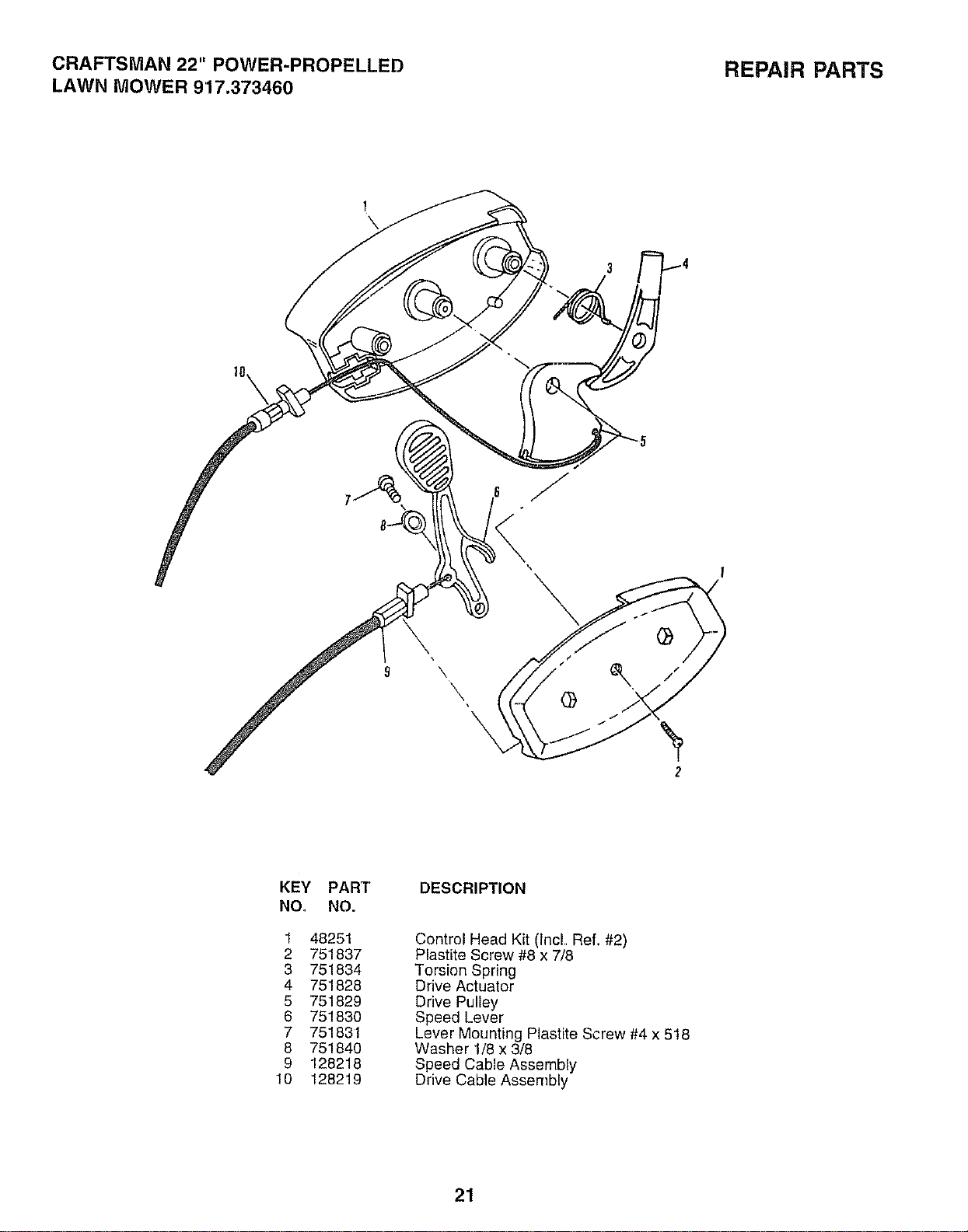
CRAFTSMAN 22" POWER-PROPELLED REPAIR PARTS
LAWN MOWER 9'17.373460
\
\
KEY PART
NO, NO.
1 48251
2 751837
3 751834
4 751828
5 751829
6 751830
7 751831
8 751840
9 128218
10 128219
DESCRIPTION
Control Head Kit (lncL Ref. #2)
Plastite Screw #8 x 7/8
Torsion Spring
Drive Actuator
Drive Pulley
Speed Lever
Lever Mounting Plastite Screw #4 x 518
Washer 1/8 x 3/8
Speed Cable Assembly
Drive Cable Assembly
21
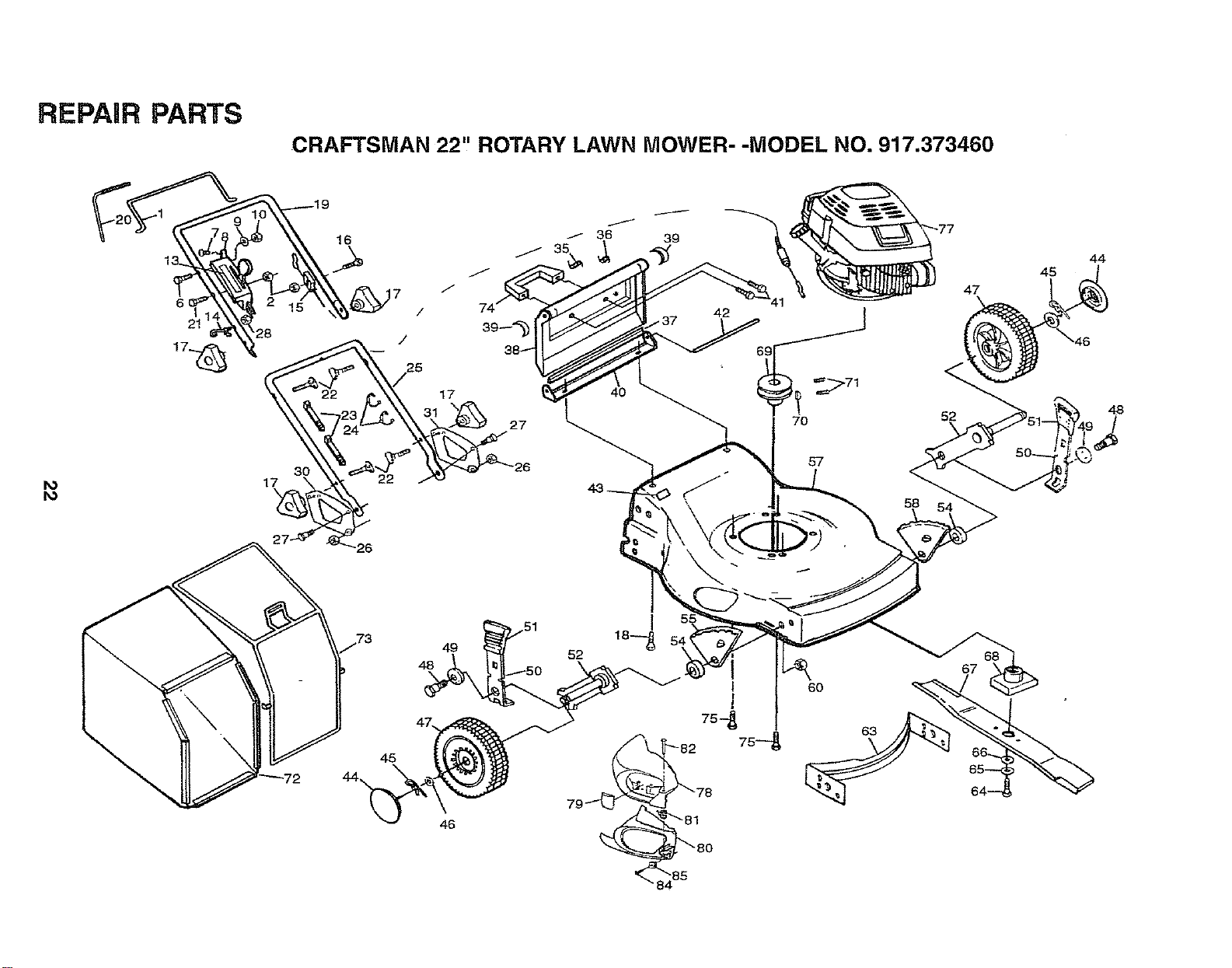
REPAIR PARTS
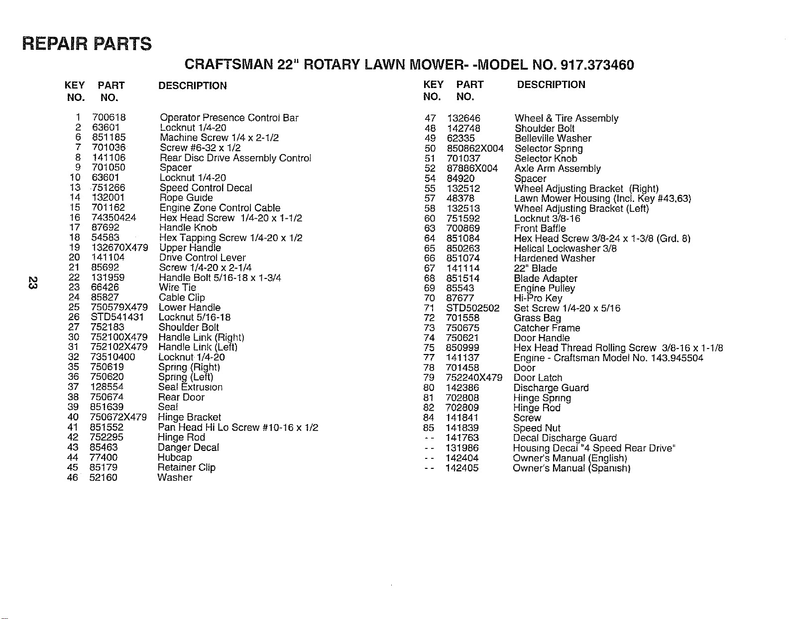
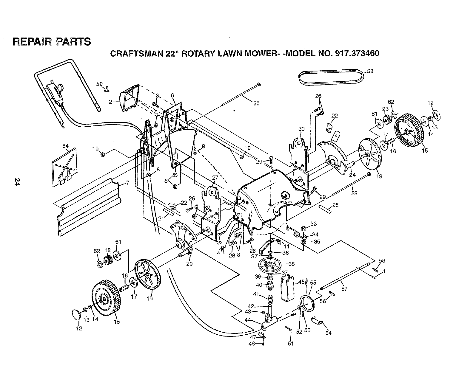
CRAFTSMAN 22" ROTARY LAWN MOWER- -MODEL NO. 917.373460
41
69
70
57
58
52 48
54
45
46
I
52
60
63
67
REPAIR PARTS
KEY PART
NO. NO.
CRAFTSMAN 22" ROTARY LAWN MOWER- -MODEL NO. 917.373460
DESCRIPTION KEY PART DESCRIPTION
NO. NO.
60
t 7OO618
2 63601
6 851185
7 701036
8 141106
9 701050
10 63601
13 751266
!4 132001
15 701162
t6 74350424
17 87692
18 54583
19 132670X479
20 141104
21 85692
22 131959
23 66426
24 85827
25 750579X479
26 STD541431
27 752183
30 752100X479
31 752102X479
32 73510400
35 750619
36 750620
37 128554
38 750674
39 851639
40 750672X479
41 851552
42 752295
43 85463
44 77400
45 85179
46 52160
Operator Presence Control Bar 47 132646
Locknut 1/4-20 48 142748
Machine Screw 1/4 x 2-1/2 49 62335
Screw #6-32 x 1/2 50 850862X004
Rear Disc Drive Assembly Control 51 701037
Spacer 52 87886X004
Locknut 1/4-20 54 84920
Speed Control Decal 55 132512
Rope Guide 57 48378
Engine Zone Control Cable 58 132513
Hex Head Screw 1/4-20 x 1-1/2 60 751592
Handle Knob 63 700869
Hex Tapping Screw 1/4-20 x 1/2 64 851084-
Upper Handle 65 850263
Drive Control Lever 66 851074
Screw 1/4-20 x 2-1/4 67 141114
Handle Bolt 5/16-18 x t-3/4 68 851514
Wire Tie 69 85543
Cable Clip 70 87677
Lower Handle 71 STD502502
Locknut 5/16-18 72 701558
Shoulder Bolt 73 750675
Handle Link (Right) 74 750621
Handle Link (Left) 75 850999
Locknut 1/4-20 77 141137
Spring (Right) 78 701458
Spring (Left) 79 752240X479
Seal Extrusion 80 142386
Rear Door 81 702808
Seal 82 702809
Hinge Bracket 84 141841
Pan Head Hi Lo Screw #10-16 x 1/2 85 141839
Hinge Rod -- 141763
Danger Decal -- 131986
Hubcap - - 142404
Retainer Clip -- 142405
Washer
Wheel & Tire Assembly
Shoulder Bolt
Belleville Washer
Selector Spring
Selector Knob
Axle Arm Assembly
Spacer
Wheel Adjusting Bracket (Right)
Lawn Mower Housing (Incl. Key #43,63)
Wheel Adjusting Bracket (Left)
Locknut 3/8-16
Front Baffle
Hex Head Screw 3/8-24 x 1-3/8 (Grd. 8)
Helical Lockwasher 3/8
Hardened Washer
22" Blade
Blade Adapter
Engine Pulley
Hi-Pro Key
Set Screw 1/4-20 x 5/16
Grass Bag
Catcher Frame
Door Handle
Hex Head Thread Rolling Screw 3/8-16 x 1-1/8
Engine - Craftsman Model No. 143.945504
Door
Door Latch
Discharge Guard
Hinge Spnng
Hinge Rod
Screw
Speed Nut
Decal Discharge Guard
Housing Decal "4 Speed Rear Drive"
Owner's Manual (English)
Owner's Manual (Spanish)
REPAIR PARTS
CRAFTSMAN 22" ROTARY LAWN MOWER- -MODEL NO. 917.373460
Io
4_
64
12
50
lo..
62
14
61
16
15
17
t9
6O
26
3O
22
27 "-- 4
26 _ 59
40-
/
51
20
_r. ,-33
54
48"_
57
61
62
23
16
19
56
12
13
14
15
REPAIR PARTS
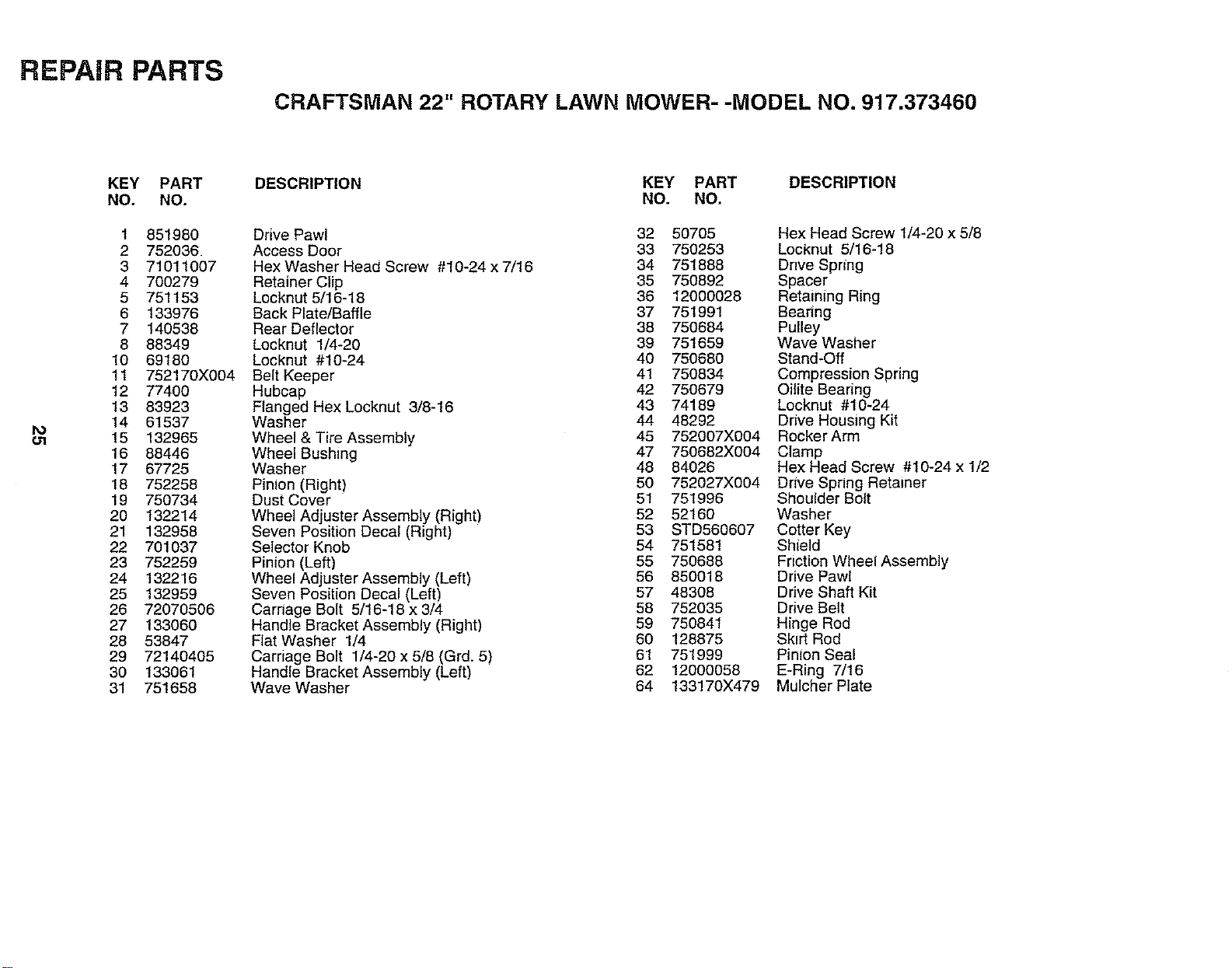
CRAFTSMAN 22" ROTARY LAWN MOWER- -MODEL NO. 917.373460
I'O
KEY PART
NO. NO.
1 851980
2 752036
3 71011007
4 700279
5 751153
6 133976
7 140538
8 88349
10 69180
11 752170X004
12 77400
13 83923
14 61537
15 132965
16 88446
17 67725
18 752258
19 750734
20 132214
21 132958
22 701037
23 752259
24 132216
25 132959
26 72070506
27 133060
28 53847
29 72140405
30 133061
31 751658
KEY PART DESCRIPTION
DESCRIPTION NO. NO.
Drive Pawl
Access Door
Hex Washer Head Screw #10-24 x 7/16
Retainer Clip
Locknut 5/16-18
Back Plate/Baffle
Rear Deflector
Locknut 1/4-20
Locknut #10-24
Belt Keeper
Hubcap
Flanged Hex Locknut 3/8-16
Washer
Wheel & Tire Assembly
Wheel Bushing
Washer
Pinion (Right)
Dust Cover
Wheel Adjuster Assembly (Right)
Seven Position Decal (Right)
Selector Knob
Pinion (Left)
Whee_ Adjuster Assembly (Left)
Seven Position Decal (Left)
Carnage Bolt 5/16-18 x 3/4
Handle Bracket Assembly (Right)
Flat Washer 1/4
Carriage Bolt 1/4-20 x 5/8 (Grd. 5)
Handle Bracket Assembly (Left)
Wave Washer
32 50705 Hex Head Screw 1/4-20 x 5/8
33 750253 Locknut 5/16-18
34 751888 Dnve Spring
35 750892 Spacer
36 12000028 Retaining Ring
37 751991 Bearing
38 750684 Pulley
39 751659 Wave Washer
40 750680 Stand-Off
41 750834 Compression Spring
42 750679 Oilite Bearing
43 74189 Locknut #10-24
44 48292 Drive Housing Kit
45 752007X004 Rocker Arm
47 750682X004 Clamp
48 84026 Hex Head Screw #10-24 x 1/2
50 752027X004 Drive Spring Retainer
51 751996 Shoulder Bolt
52 52160 Washer
53 STD560607 Cotter Key
54 751581 Shield
55 750688 Friction Wheel Assembly
56 850018 Drive Pawl
57 48308 Drive Shaft Kit
58 752035 Drive Belt
59 750841 Hinge Rod
60 128875 Skirt Rod
61 751999 Pinton Seal
62 12000058 E-Ring 7/16
64 133170X479 Mulcher Plate
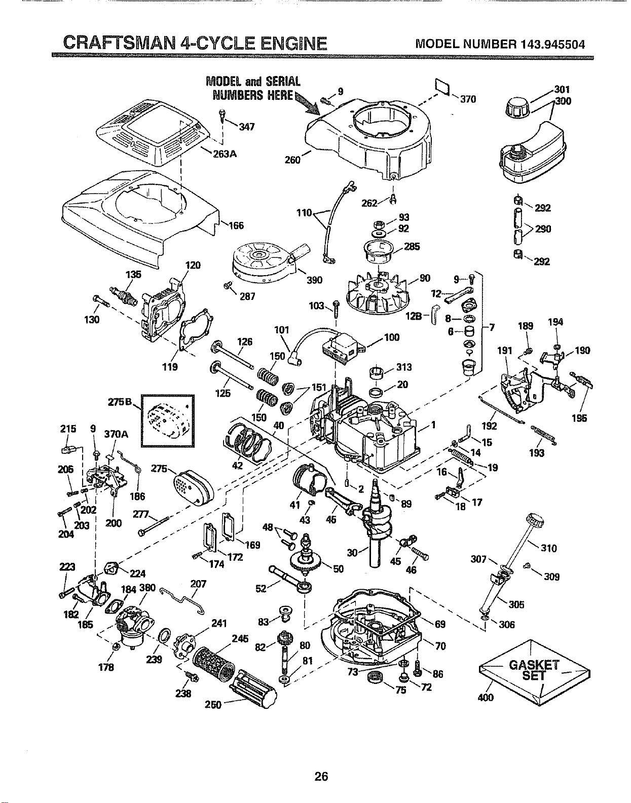
CRAFTSMAN 4=CYCLE ENGINE MODELNUMBER143.945504
215
119
120
125
9 370A
2OO
41
46
/
178
>
241 83"/(_
245 82/J_i 80
_/81
-7 189 194
14 193
26
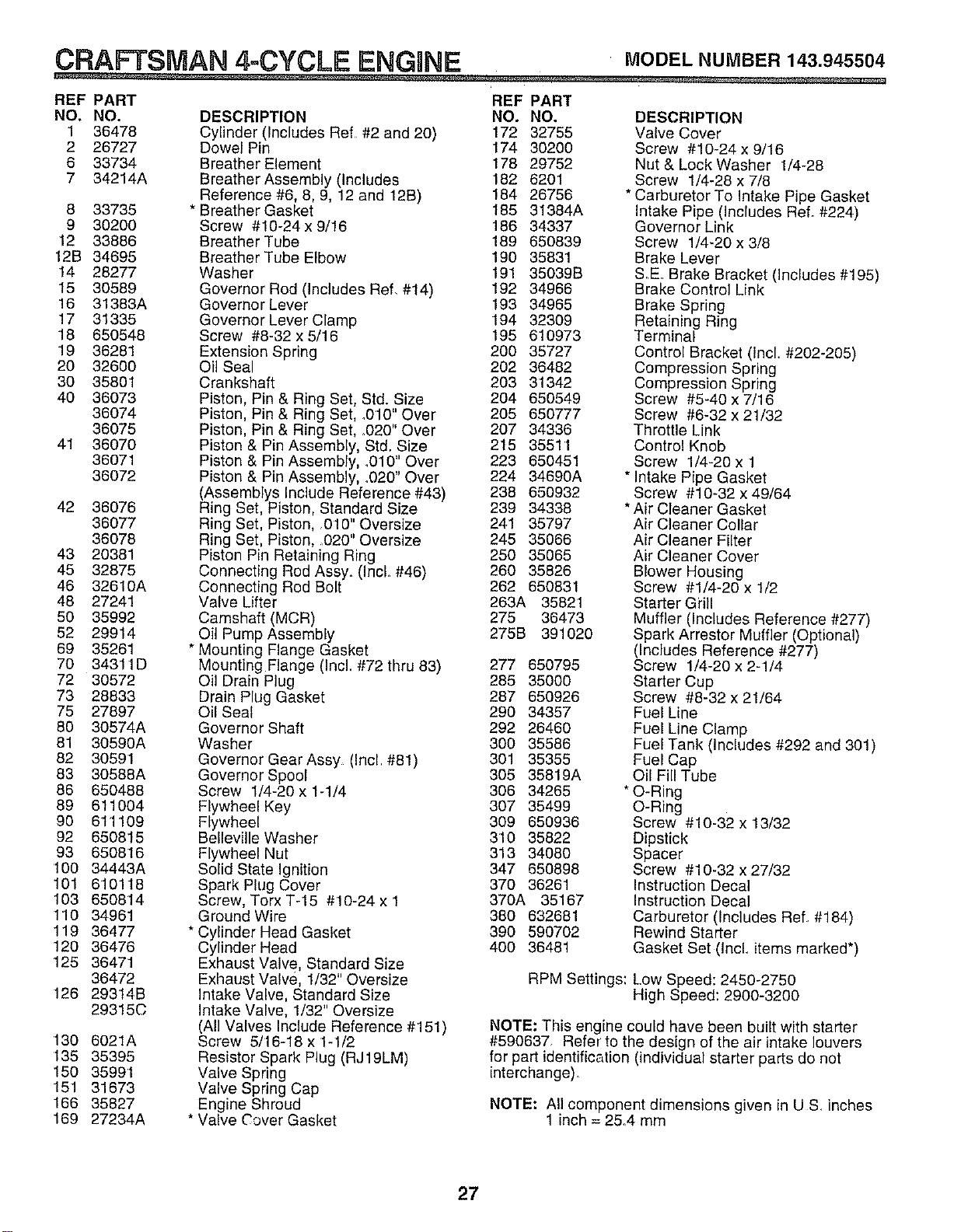
CRAFTSMAN 4=CYCLE ENGINE MODELNUMBER143.945504
REF PART REF PART
NO. NO DESCRIPTION NO. NO. DESCRIPTION
1 36478
2 26727
6 33734
7 34214A
8 33735
9 30200
12 33886
12B 34695
14 28277
15 30589
16 31383A
17 31335
18 650548
19 36281
20 32600
30 35801
40 36073
36074
36075
41 36070
36071
36072
42 36076
36077
36078
43 20381
45 32875
46 32610A
48 27241
50 35992
52 29914
69 35261
70 34311D
72 30572
73 28833
75 27897
80 30574A
81 30590A
82 30591
83 30588A
86 650488
89 611004
90 611109
92 650815
93 650816
t00 34443A
101 610118
103 650814
110 34961
119 36477
120 36476
125 36471
36472
126 293t4B
29315C
t30 6021A
135 35395
150 35991
151 31673
166 35827
169 27234A
Cylinder (Includes Ref #2 and 20) 172 32755
Dowel Pin 174 30200
Breather Element 178 29752
Breather Assembly (Includes 182 6201
Reference #6, 8, 9, 12 and 12B) 184 26756
* Breather Gasket 185 31384A
Screw #10-24 x 9/16 186 34337
Breather Tube 189 650839
Breather Tube Elbow 190 35831
Washer 191 35039B
Governor Rod (Includes Ref, #14) 192 34966
Governor Lever 193 34965
Governor Lever Clamp 194 32309
Screw #8-32 x 5/16 195 610973
Extension Spring 200 35727
Oil Seal 202 36482
Crankshaft 203 31342
Piston, Pin & Ring Set, Std. Size 204 650549
Piston, Pin & Ring Set, .010" Over 205 650777
Piston, Pin & Ring Set, .020" Over 207 34336
Piston & Pin Assembly, Std. Size 215 35511
Piston & Pin Assembly, .010" Over 223 650451
Piston & Pin Assembly, .020" Over 224 34690A
(Assemblys Include Reference #43) 238 650932
Ring Set, Piston, Standard Size 239 34338
Ring Set, Piston, .010" Oversize 241 35797
Ring Set, Piston, 020" Oversize 245 35066
Piston Pin Retaining Ring 250 35065
Connecting Red Assy. (IncL #46) 260 35828
Connecting Rod Bolt 262 650831
Valve Lifter 263A 35821
Camshaft (MCR) 275 36473
Oil Pump Assembly 275B 391020
* Mounting Flange Gasket
Mounting Flange (Incl. #72 thru 83) 277 650795
Oil Drain Plug 285 35000
Drain Plug Gasket 287 650926
Qil Seal 290 34357
Governor Shaft 292 26460
Washer 300 35586
Governor Gear Assy (Incl #81) 301 35355
Governor Spool 305 35819A
Screw 1/4-20 x 1-1/4 308 34265
Flywheel Key 307 35499
Flywheel 309 650936
Bellevilte Washer 310 35822
Flywheel Nut 313 34080
Solid State Ignition 347 650898
Spark Pk_g Cover 370 36261
Screw, Torx T-15 #10-24 x 1 370A 35167
Ground Wire 380 632681
* Cylinder Head Gasket 390 590702
Cylinder Head 400 36481
Exhaust Valve, Standard Size
Exhaust Valve, 1/32" Oversize
Intake Valve, Standard Size
Intake Valve, 1/32" Oversize
(All Valves Include Reference #'151)
Screw 5/16-16 x 1-l/2
Resistor Spark Plug (RJ 19LM)
Valve Spring
Valve Spring Cap
Engine Shroud
* Valve Cover Gasket
Valve Cover
Screw #10-24 x 9/16
Nut & Lock Washer 1/4-28
Screw 1/4-28 x 7/8
* Carburetor To Intake Pipe Gasket
intake Pipe (Includes Ref. #224)
Governor Link
Screw 1/4-20 x 3/8
Brake Lever
S.E. Brake Bracket (Includes #195)
Brake Control Link
Brake Spring
Retaining Ring
Terminal
Control Bracket (Incl. #202-205)
Compression Spring
Compression Spring
Screw #5-40 x 7/16
Screw #6-32 x 21/32
Throttle Link
Control Knob
Screw 1/4-20 x 1
* Intake Pipe Gasket
Screw #10-32 x 49/64
* Air Cleaner Gasket
Air Cleaner Collar
Air Cleaner Filter
Air Cleaner Cover
Blower Housing
Screw #1/4-20 x 1/2
Starter Grill
Muffler (Includes Reference #277)
Spark Arrestor Muffbr (Optional)
(Includes Reference #277)
Screw 1/4-20 x 2-1/4
Starter Cup
Screw #8-32 x 21/64
Fuel Line
Fuel Line Clamp
Fuel Tank (Includes #292 and 301)
Fuel Cap
Oil Fill Tube
* O-Ring
O-Ring
Screw #10-32 x 13/32
Dipstick
Spacer
Screw #10-32 x 27/32
Instruction Decal
Instruction Decal
Carburetor (Includes Ref. #184)
Rewind Starter
Gasket Set (IncL items marked*)
RPM Settings: Low Speed: 2450-2750
High Speed: 2900-3200
NOTE: This engine could have been built with starter
#590637 Refer to the design of the air intake louvers
for part identification (individual starter parts do not
interchange).
NOTE: Aii component dimensions given in US. inches
1 inch = 2&4 mm
27
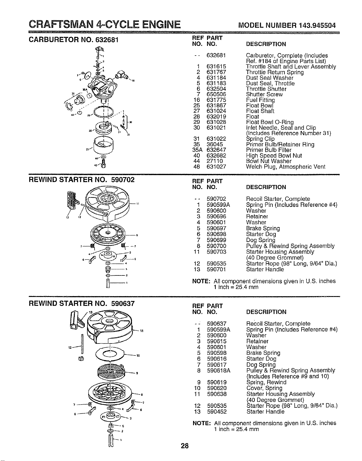
CRAFTSMAN 4-CYCLE ENGINE MODELNUMBER143.945504
CARBURETOR NO. 632681 REF PART
NO, NO. DESCRIPTION
25 _, _'_
44_
40/
-- 632681
1 631615
2 631767
4 631184
5 631183
6 632504
7 650506
16 631775
25 631867
27 631024
28 632019
29 631028
30 631021
31 631022
35 36045
35A 632647
40 632682
44 27110
48 631027
Carburetor, Complete (Includes
Ref. #184 of Engine Parts List)
Throttle Shaft and Lever Assembly
Throttie Return Spring
Dust Seal Washer
Dust Seal, Throttle
Throttle Shutter
Shutter Screw
Fuel Fitting
Float Bowl
Float Shaft
Float
Float Bowl O-Ring
Inlet Needle, Seat and Clip
(Includes Reference Number 31)
Spring Clip
Primer Bulb/Retainer Ring
Primer Bulb Filter
High Speed Bowl Nut
Bowl Nut Washer'
Welch Plug, Atmospheric Vent
i i
REWIND STARTER NO. 590702
. 4
--S
--2
--t
REF PART
NO. NO. DESCRIPTION
-- 590702 Recoil Starter, Complete
1 590599A Spring Pin (Includes Reference #4)
2 590600 Washer
3 590696 Retainer
4 590601 Washer
5 590697 Brake Spring
6 590698 Starter Dog
7 590699 Dog Spring
8 590700 Pulley & Rewind Spring Assembly
11 590703 Starter Housing Assembly
(40 Degree Grommet)
12 590535 Starter Rope (98" Long, 9/64" Dia.)
13 590701 Starter Handle
NOTE: A!l component dimensions given in U.S. inches
1 inch = 254 mm
REWIND STARTER NO. 590637
28
REF PART
NO. NO. DESCRIPTION
-: 590637
1 590599A
2 590600
3 590615
4 590601
5 590598
6 590616
7 590617
8 596618A
9 590619
10 590620
11 590638
12 590535
13 590452
Recoil Starter, Complete
Spring Pin (Includes Reference #4)
Washer
Retainer
Washer
Brake Spring
Starter Dog
Dog Spring
Pulley & Rewind Spring Assembly
(Includes Reference #9 and 10)
Spring, Rewind
Cover, Spring
Starter Housing Assembly
(40 Degree Grommet)
Starter Rope (98" Long, 9/64" Dia.)
Starter Handle
NOTE: All component dimensions given in U.S. inches
1 inch = 25.4 mm

SERVICE NOTES
29

SERVICE NOTES
3O
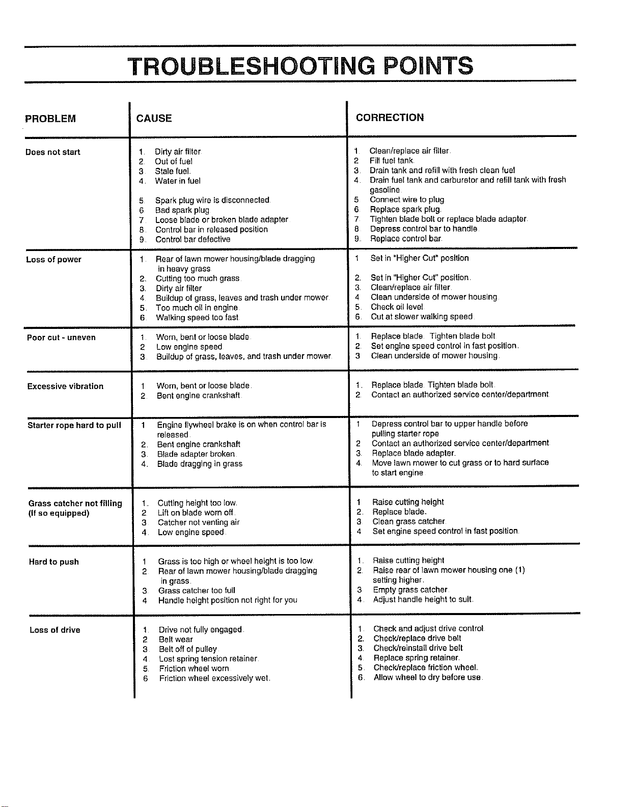
TROUBLESHOOTING POINTS
PROBLEM
Doesnot start
Loss of power
Poorcut*uneven
Excessive vibration
Starter rope herd to pull
Grass catcher not _ling
(if so equipped)
Hard to push
Loss of drive
CAUSE
2
3
4
Dirtyair filter
Out of fuel
Stale fuel.
Waterin fuel
5 Spark plug wire is disconnected
6 Bad sparkplug
7 Loose blade or broken blade adapter
8 Control bar in released position
9 Control bar defective
1 Rear of lawn mower housing/blade dragging
in heavy grass
2 Cutting too much grass
3 Dirty air filter
4 Buildup of grass, leaves and trash under mower
5 Too much oifin engine
6 Walking speed too fast
1 Worn, bent or loose blade
2 Low engine speed
3 Buildup of grass, leaves, and trash under mower
1 Worn, bent or loose blade
2 Bentengine crankshaft
1 Engine flywheel brake is on when control bar is
released
2 Bent engine crankshaft
3 Blade adapter broken
4 Blade dragging in grass
1 Cutting height too low
2 Lift on blade worn off
3 Catcher not venting air
4 Low engine speed
1 Grass is too high or wheel height is too low
2 Rear of lawn mower housing/blade dragging
in grass
3 Grass catcher too full
4 Handle height position not right for you
1 Drive not fully engaged
2 Belt wear
3 Belt off of pulley
4 Lost spring tension retainer
5 Friction wheel worn
6 Fdction wheel excessively wet
CORRECTION
1 Clean/replace airfiIter
2 Fill fuel tank
3 Drain tank and refill with fresh clean fuel
4 Drain rue! tank and carburetor and refill tank with fresh
gasoline
5 Connect wire to plug
6 Replace spark pkJg
7 Tighten blade bolt or replace blade adapter
8 Depress control bar to handle
9 Replace control bar
Set in "Higher Cat" position
2 Set in "Higher Cut" position
3 Clean/replace air filter
4 Clean underside of mower housing
5 Check oilleve!
6 Cot at slower walking speed
1 Replace blade Tighten blade bolt
2 Set engine speed control in fast position
3 Clean underside of mower housing
1 Replace blade Tighten blade bolt
2 Contact an authorizedservice center/department
1 Depress control bar to upper handle before
pulling starter rope
2 Contact an authodzed service center/department
3 Replace blade adapter
4 Move lawn mower to cat grass or to hard surface
to start engine
1 Raise cutting height
2 Replace blade
3 Clean grass catcher
4 Set engine speed control in fast position
1 Raise cutting height
2 Raise rear of lawn mower housing one (1)
setting higher
3 Empty grass catcher
4 Adjust handle height to suit
1 Check and adjust drive control
2, Check/replace drive belt
3 Check/rainstall drive beff
4 Replace spring retainer
5 Check/replace friction wheel
6 Allow wheel to dry before use
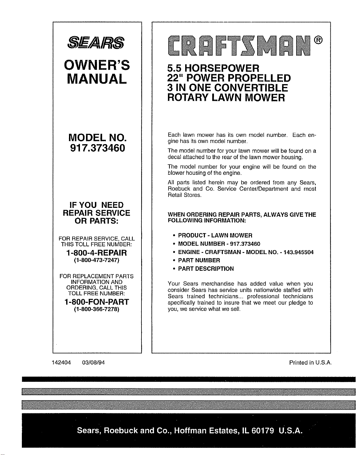
8EA/RS
OWNER'S
MANUAL
MODEL NO.
917.373460
IF YOU NEED
REPAIR SERVICE
OR PARTS:
FOR REPAIR SERVICE, CALL
THIS TOLL FREE NUMBER:
1-800-4-REPAIR
(1-800-473-7247)
FOR REPLACEMENT PARTS
INFORMATION AND
ORDERING, CALL ]'HIS
TOLL FREE NUMBER:
1-800-FON-PART
(1-800-366-7278)
®
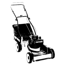
5.5 HORSEPOWER
22" POWER PROPELLED
3 IN ONE CONVERTIBLE
ROTARY LAWN MOWER
Each lawn mower has its own model number_ Each en-
gine has its own model number_
The model number for' your lawn mower will be found on a
decal attached to the rear of the lawn mower housing
The model number for your engine will be found on the
blower' housing of the engine.
All parts listed herein may be ordered from any Sears,
Roebuck and Co. Service Center/Department and most
Retail Stores.
WHEN ORDERING REPAIR PARTS, ALWAYS GIVE THE
FOLLOWING INFORMATION:
• PRODUCT- LAWN MOWER
• MODEL NUMBER - 917o373460
• ENGINE - CRAFTSMAN - MODEL NO. - 143,945504
• PART NUMBER
• PART DESCRIPTION
Your Sears merchandise has added value when you
consider Sears has service units nationwide staffed with
Sears trained technicians__ professional technicians
specifically trained to insure that we meet our' pledge to
you, we service what we sell
142404 03/08/94 Printed in U.S_A_