Loading ...
Loading ...
Loading ...
CONNECT BATTERY (See Fig. 2)
CAUTION: Do not short battery termi-
nals. Before connecting battery, re-
move metal bracelets, wristwatch
bands, rings, etc.
Positive terminal must be connected
first to prevent sparking from acciden-
tal grounding°
- Lift hood to raised position.
o Open terminal access doors, remove terminal protec-
tive caps and discard..
° tf this battery is put into service after month and year
indicated on label (label located between terminals)
charge battery for minimum of one hour at 6-10 amps.
= First connect RED battery cable to positive (+) battery
terminal with hex bolt, ftat washer, lockwasher and hex
nut as shown., Tighten securely.
° Connect BLACK grounding cable to negative (-) battery
terminal with remaining hex bolt, flat washer, lock
washer and hex nuL Tighten securely°
• Close terminal access doorsv
Use terminal access doors for:
° Inspection for secure connections (to tighten hard-
ware),,
* Inspection for corrosion.
o Testing battery.
= Jumping (if required).
o Periodic charging_
HEX NUT
DISCARD
TERMINAL
PROTECTIVE
CAPS _
TERMINAL "'"
ACCESS
DOOR ;' _.'_"_
VENT HOLE _ _ ._ j
(KEEP CLEAN
LOCK FLAT
WASHER WASHER
HEX
-BOLl"
POSITIVE
(RED)
CABLE
NEGATIVE
(BLACK)
CABLE
FIG. 2
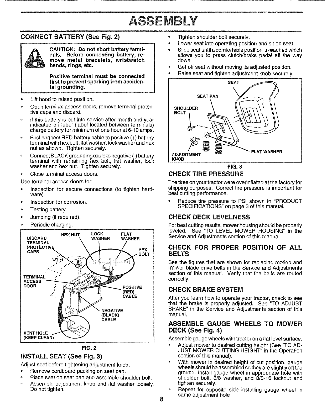
INSTALL SEAT (See Fig. 3)
Adjust seat before tightening adjustment knob.
= Remove cardboard packing on seat pan,,
o Place seat on seat pan and assemble shoulder bolt.
° Assemble adjustment knob and flat washer Ioosely_
Do not tighten°
o Tighten shoulder bolt securely,
o Lower seat into operating position and sit on seat.
• Slide seat until a comfortable position is reached which
allows you to press clutch!brake pedal all the way
down°
° Get off seat without moving its adjusted position_
• Raise seat and tighten adjustment knob securely.
SEAT
SEAT PAN
SHOULDER
BOLT
ADJUSTMENT
KNOB
FLAT WASHER
FIG, 3
CHECK TIRE PRESSURE
The tires on your tractor were overinflated at the factory for
shipping purposes. Correct tire pressure is important for
best cutting performance.
o Reduce tire pressure to PSI shown in "PRODUCT
SPECIFICATIONS" on page 3 of this manual
CHECK DECK LEVELNESS
For best cutting results, mower housing should be properly
teveled_ See 'q-O LEVEL MOWER HOUSING" in the
Service and Adjustments section of this manual.
CHECK FOR PROPER POSITION OF ALL
BELTS
See the figures that are shown for replacing motion and
mower bfade drive belts in the Service and Adjustments
section of this manual Verify that the belts are routed
correctly°
CHECK BRAKE SYSTEM
After you learn how to operate your' tractor, check to see
that the brake is properly adjusted, See "TO ADJUST
BRAKE" in the Service and Adjustments section of this
manual.
ASSEMBLE GAUGE WHEELS TO MOWER
DECK (See Fig. 4)
Assemble gauge wheels with tractor on a flat level surface.
. Adjust mower to desired cutting height (See '_FOAD-
JUST MOWER CUTTING HEIGHT in the Operation
section of this manual).
o With mower in desired height of cut position, gauge
wheels should be assembled so they are slightly off the
ground° install gauge wheel in appropriate hole with
shoulder bolt, 3/8 washer, and 3/8-16 Iocknut and
tighten securely.
. Repeat for opposite side installing gauge wheel in
same adjustment ho!_
Loading ...
Loading ...
Loading ...