
®
MODEL NUMBER 917.252590
° Assembly
oOperation
° Customer Responsibilities
o Service and Adjustments
Repair Parts
OWNER'S MANUAL
CAUTION: Read and follow all safety rules and instructions before operating this equipment.
FOR CONSUMER ASSISTANCE HOT LINE, CALL "TH_STOLL FREE NUMBER: 1-800-659-5917
_,, II I'1'11111 ' '111'
.......... ,,, j,,, ,

SAFETY RULES
Safe Operation Practices for Ride-On Mowers
IMPORTANT: THIS CUTTING MACHINE IS CAPABLE OF AMPUTATING HANDS AND FEET AND THROWING OBJECTS.
FAILURE TO OBSERVE THE FOLLOWING SAFETY INSTRUCTIONS COULD RESULT IN SERIOUS INJURY OR DEATH
I. GENERAL OPERATION
• Read, understand, and follow all instructions in the manual
and on the machine before starting.
• Only allow responsible adults, who are familiar with the
instructions, to operate the machine.
• Clear the area of objects such as rocks, toys, wire, etc.,
which could be picked up and thrown by the blade.
• Be sure the areais clear of other people before mowing Stop
machine if anyone enters the area
• Never carry passengers
• Do not mow in reverse unless absolutely necessary Always
look down and behind before and while backing.
• Be aware of the mower discharge direction and do not point
it at anyone. Do not operate the mower without either the
entire grass catcher or the guard in place
• Slow down before turning
• Never leave a running machine unattended Always turn off
blades, set parking brake, stop engine, and remove keys
before dismounting.
• Turn off blades when not mowing
• Stop engine before removing grass catcher or unclogging
chute.
. Mow only in daylight or good artificial light.
" Do not operate the machine while under the influence of
alcohol or drugs
• Watch for traffic when operating near or crossing roadways.
• Use extra care when loading or unloading the machine into
a trailer or truck_
!1, SLOPE OPERATION
Slopes are a major factor related to loss-of-control and
tipover accidents, which can result in severe injuryor death.
All slopes require extra caution. If you cannot back up the
slope or if you feel uneasy on it, do not mow it.
DO:
. Mow up and down slopes, not across.
• Remove obstacles such as rocks, tree limbs, etc..
• Watch for holes, ruts, or bumps. Uneven terrain could
overturn the machine. Tall grass can hide obstacles,
• Use siow speed. Choose a low gear so that you wiU not have
to stop or shift while on the slope
• Follow the manufacturer's recommendations for wheef
weights or counterweights to improve stability.
• Use extra care with grass catchers or other attachments.
These can change the stabifity of the machine.
. Keep all movement on the slopes stowand gradual Do not
make sudden changes in speed or direction
• Avoid starting or stopping on a slope° If tires lose traction,
disengage the blades and proceed slowly straight down the
slope.
DO NOT:
• Donottumonslopesunlessnecessary,andthen,turnsiowty
and gradually downhill, if possible_
• Do not mow near drop-offs, ditches, or embankments. The
mower could suddenly turn over if a wheel is over the edge
of a cliff or ditch, or if an edge caves in_
• Do not mow on wet grass., Reduced traction could cause
sliding
• Do not try to stabilize the machine by putting your foot on the
ground
• Do not use grass catcher on steep siopes
iii. CHILDREN
Tragic accidents can occur if the operator is not alert to the
presence of children. Children are often attracted to the
machine and the mowing activity_ Never assume that
children will remain where you Iast saw them
• Keep chiidren out of the mowing area and under the watchful
care of another responsible adult.
o Be alert and turn machine off if children enter the area
- Before arrd when backing, look behind and down for small
children
- Never carry children They may fall off and be seriously
injured or interfere with safe machine operation
° Never allow children to operate the machine.
• Use exha care when approaching blind corners, shrubs,
trees, or other objects that may obscure vision.
IV, SERVICE
- Use extra care in handling gasoline and other fuels, They are
flammable and vapors are explosive
Use only an approved container
Never remove gas cap or add fuel with the engine
running. Allow engine to cool before refueling. Do not
smoke
Never refuel the machine indoors
Never store the machine or fuel container inside where
there is an open flame, such as a water heater.
• Never run a machine inside a closed area.
• Keep nuts and bolts, especially blade attachment bolts, tight
and keep equipment in good condition
• Never tamper with safety devices Check their proper
operation regularly.
• Keep machine free of grass, leaves, or other debris build-up_
Clean oil or fuel spillage Allow machine to cool before
storing
• Stop and inspect the equipment if you strike an object.
Repair, if necessary, before restarting.
• Never make adjustments or repairs with the engine running_
• Grass catcher components are subject to wear, damage, and
deterioration, which could expose moving parts or alfow
objects to be thrown. Frequently check components and
replace with manufacturer's recommended parts, when nec-
essary.
. Mower blades are sharp and can cut Wrap the blade(s) or
wear gloves, and use extra caution when servicing them
• Check brake operation frequently. Adjust and service as
required
Look for this symbol to point out im-
portant safety precautions, it means
CAUTIONH! BECOMEALERT!H YOUR
SAFETY IS INVOLVED.
CAUTION: Always disconnect spark plug
wire and place wire where it cannot contact
spark plug in order to prevent accidental
starting when setting up, transporting,
adjusting or' making repairs.
WARNING A
The engine exhaust from this product con-
tains chemicals known to the State of Califor-
nia to cause cancer, birth defects, or other
reproductive harm.
i

CONGRATULATI_ONS on _,our purchase of a Sears
tractor. It has been designea, engJneeree anct manuTac-
tured to give you the best possible dependability and
performance°
Should you experience any problem you cannot easily
remedy, please contact your nearest Sears Service Cen-
tedDepartmenL We have competent, well-trained tech-
nicians and the proper tools to service or repair this trac-
tor.
Please read and retain this manual. The instructions wil!
enable you to assemble and maintain your unit properly.
Always observe the "SAFETY RULES",
vlODEL
NUMBER 917.252590
SERIAL
NUMBER
DATE OF PURCHASE
THE MODEL AND SERIAL NUMBERS WILL BE FOUND
ON A PLATE UNDER THE SEAT.
YOU SHOULD RECORD BOTH SERIAL NUMBER AND
DATE OF PURCHASE AND KEEP 1NA SAFE PLACE
FOR FUTURE REFERENCE°
MAINTENANCE AGREEMENT
A Sears maintenance agreement is available on this prod-
ucL Contact your nearest Sears store for details.,
CUSTOMER RESPONSIBILITIES
. Read and observe the safety rules.
• Fol!ow a regutar schedule in maintaining, caring for and
using your tractor.
. Follow the instructions under "Customer Responsibili-
ties" and "Storage" sections of this owner's manual.
PRODUCT SPECIFBCAT ,ONS
HORSEPOWER: 15,5
GASOLINE CAPACITY 3.5 GALLONS
AND TYPE: UNLEADED REGULAR
OIL TYPE (API-SF/SG): SAE 10W-30 (above 32°F)
SAE 5W-30 (below 32°F)
OIL CAPACITY: W/FILTER: 4.0 PINTS
W/O FILTER: 3.5 PINTS
SPARK PLUG: CHAMPION RC12YC
(GAP: 040")
VALVE CLEARANCE: NOT ADJUSTABLE
GROUND SPEED (MPH): FORWARD: 562
REVERSE: 2.4
TIRE PRESSURE: FRONT: 14 PSI
REAR: 10 PSI
CHARGING SYSTEM: 3 AMPS BATTERY
5 AMPS HEADLIGHTS
BLADE BOLT TORQUE: 30-35 FT LBSo
WARNING: This tractor is equipped with an internal
combustion engine and should not be used on or near any
unimproved forest-covered, brush-covered or grass-cov-
ered land unless the engine's exhaust system is equipped
with aspark arrester meeting applicable local or state laws
(if any). If aspark arrester is used, it should be maintained
in effective working order by the operator.
In the state of California the above is required by law
(Section 4442 of the California Public Resources Code).
Other states may have similar taws. Federal laws apply on
federal lands. A spark arrester for the muffler isavailable
through your nearest Sears Authorized Service Center
(See REPAIR PARTS section of this manual).
nl. n'"'ll, I'nuun'l . n .i n"l_._l,"_qH -
LIMITED TWO YEAR WARRANTY ON CRAFTSMAN R D1NG EQUIPMENT
For two (2) years from the date of purchase, if this Craftsman Riding Equipment is maintained, lubricated and tuned up according
to the instructions in the owner's manual, Sears will repair or replace, free of charge, any parts found to be defective in matedal
or workmanship,
This Warranty does not cover:
• Expendable items which become worn during normal use, such as blades, spark plugs, air cleaners, belts, etc
o Tire replacement or repair caused by punctures from outside objects, such as nails, thorns, stumps, or glass
. Repairs necessary because of operator abuse, negligence, improper storage or accident or the failure to maintain the
equipment according to the instructions contained in the owner's manual
. Riding equipment used for commercial or rental purposes.
LiMiTED 90 DAY WARRANTY ON BATTERY
For ninety (90) days from date of purchase, if any battery included with this dding equipment proves defective in matefiat or
workmanship and our testing determines the battery will not hold acharge, Sears will replace the battery at no charge
IN-HOME WARRANTY SERVICE ON YOUR CRAFTSMAN RIDING EQUIPMENT iS AVAILABLE AT NO-CHARGE FOR 30
DAYS FROM THE DATE OF PURCHASE PLEASE CONTACT YOUR NEAREST SERVICE CENTER. AFTER 30 DAYS
FROM THE DATE OF PURCHASE, WARRANTY SERVICE IS AVAILABLE BY TAKING YOUR CRAFTSMAN RIDING EQUIP-
MENT TO YOUR NEAREST SEARS SERVICE CENTER. (1N-HOME WARRANTY SERVICE WILL STILL BE AVAILABLE
AFTER 30 DAYS FROM THE DATE OF PURCHASE BUT A STANDARD TRIP CHARGE WILL APPLY,) THIS WARRANTY
APPLIES ONLY WHILE THIS PRODUCT IS IN THE UNITED STATES
This Warranty gives you specific legal rights, and you may also have other rights which may vary from state to state
SEARS, ROEBUCK AND CO., D/817 WA, HOFFMAN ESTATES, IL 60179
i i .... lu u u uul=l u i ii •......... ................ i
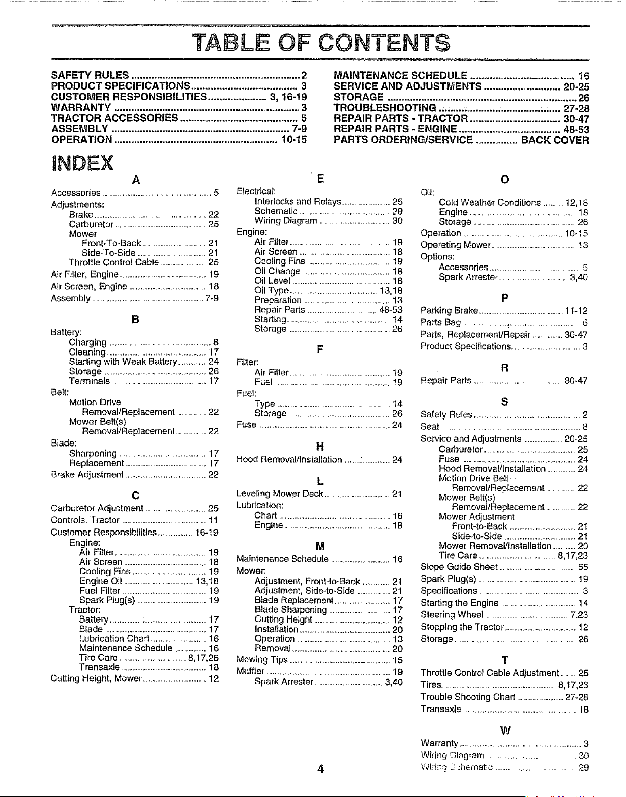
TABLE OF CONTENTS
SAFETY RULES ............................................................ 2
PRODUCT SPECIFICATIONS ...................................... 3
CUSTOMER RESPONSIBILITIES ..................... 3, 16-19
WARRANTY .................................................................. 3
TRACTOR ACCESSORIES .......................................... 5
ASSEMBLY ............................................................... 7-9
OPERATION .......................................................... 10-15
MAINTENANCE SCHEDULE ..................................... 16
SERVICE AND ADJUSTMENTS ........................... 20-25
STORAGE ................................................................... 26
TROUBLESHOOTING .,.,,... ......... ..................... ,. 27-28
REPAIR PARTS - TRACTOR ................................ 30-47
REPAIR PARTS - ENGINE .................................... 48-53
PARTS ORDERINGISERVIOE ............... BACK COVER
NDEX
A
Accessories ............................................................... 5
Adjustments:
Brake .....................................................22
Carburetor ..........................................25
Mower
Front-To-Back .......................... 21
Side-To-Side ...................................21
Throttle Control Cable .......................25
Air Filter, Engine ...................................................19
Air Screen, Engine ............................... 18
Assembly ................................................................. 7-9
B
Battery:
Charging .....................................................8
Cleaning ........................................... 17
Starting with Weak Battery ..............24
Storage .........................................................26
Terminals ..................................................... 17
Belt:
Motion Drive
Removal/Replacement ..............22
Mower Belt(s)
Remova}/Replacement ...............22
Blade:
Sharpening ................................................17
Replacement .........................................17
Brake Adjustment .......................................22
C
Carburetor Adjustment ........................... 25
Controls, Tractor ...........................................11
Customer Responsibilities ...................16-19
Engine:
Air Filter ..................................................19
Air Screen ......................................18
Cooling Fins .....................................19
Englne Oil ...........................................13,18
Fuel Filter ..................................................19
Spark Plug(s) ............................. 19
Tractor:
Battery ..............................................17
Blade .....................................................17
Lubrication Chart ............................16
Maintenance Schedule ...............16
Tire Care ...................................... 8,17,26
Transaxle ,,...........................................18
Cutting Height, Mower .............................12
E
Electrical:
Intedocks and Relays ......................25
Schematic ..................................................29
Wiring Diagram ................................... 30
Engine:
Air Filter ...............................................19
Air Screen .............................................18
CoolingFins.....................................19
Oil Change ..........................................18
Oil Level .................................................. 18
Oil Type ......................................13,18
Preparation ..................................... 13
Repair Parts ..................................48-53
Starting .............................................. 14
Storage .......................................................26
F
Filter:
Air Filter ........................................... 19
Fuel .......................................................... 19
Fuel:
Type ........................................................ 14
Storage .............................................26
Fuse ....................................................... 24
H
Hood Removal/installation .........:..............24
L
Leveling Mower Deck ...............................21
Lubrication:
Chart ........................................................16
Engine ......................................................18
M
Maintenance Schedule ............................ 16
Mower:
Adjustment, Front-to-Back ........... 2t
Adjustment, Side-to-Side ............... 2t
Blade Replacement ..........................17
Blade Sharpening ..............................t7
Cutting Height ..........................................12
Installation .........................................20
Operation ............................................13
Removal .............................................20
Mowing Tips ...............................................15
Muffler ............................................................19
Spark Arrester ...............................3,40
O
Oil:
CoLd Weather Conditions ..........12,18
Engine ...................................................... 18
Storage ...............................................26
Operation ............................................................! 0-15
Operating Mower ......................................13
Options:
Accessories ..................................... 5
Spark Arrester .......................................3,40
P
Parking Brake ..................................... 11-12
Parts Bag .....................:..................................6
Parts, Replacement/Repair ...............30-47
P_oduct Specifications .....................................3
R
Repair Parts .........................................30-47
Safety Rules .................................................2
Seat .............................................................. 8
Service and Adjustments ............... 20-25
Carburetor° .................................................25
Fuse ............................................................... 24
Hood Removal/Installation ...............24
Motion Ddve Belt
Removal/Replacement ..............22
Mower Belt(s)
Removal!Replacement ................22
Mower Adjustment
Front-to-Back ...............................21
Side-to-Side ............................. 21
Mower Removalllnstallation .......... 20
Tire Care ......................................8,t7,23
Slope Guide Sheet .....................................55
Spark Plug(s) ........................................... 19
Specifications ............................................................3
Starting the Engine ............................ 14
Steering Wheel .........................................7,23
Stopping the Tractor ..................................12
Storage ...........................................................26
T
Throttle Control Cable Adjustment ........25
Tires ..............................................................8,17,23
Trouble Shooting Chart ................... 27-28
Transaxle ....................................................18
4
W
Warranty ............................................................3
Wiring Diagram ............................. 30
\,Viri_:g 17:ilernatic ............................ 29
........... , , ,,i
i1,,,i
ACCESSORIES AND ATTACHMENTS
,,,= , i,, ,..... _ , , i...... i,l,,Hi
These accessories and attachments were available through most Sears retail outlets and service centers when the tractor was purchased,
Most Sears stores can order these items for you when you provide the model number of your tractor.
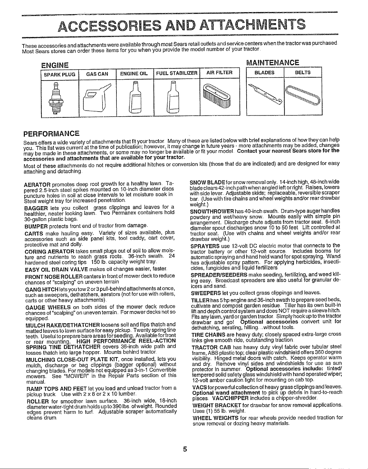
ENGINE
SPARK'PLUGGAS CAN
ENGINE OIL
FUEL STABILIZER
AIRFILTER
%
MAINTENANCE
I BLADES BELTS
PERFORMANCE
Sears offers a wide var ety of attachments that fit your tractor Many of these are listed below with brief explanations of how they can help
you,, This list was current at the time of publication; however, it may change in future years - more attachments may be added, changes
may be made in these attachments, or some may no longer be available or fit your model Contact your nearest Sears store for the
accessories and attachments that are available for your tractor.
Most of these attachments do not require additional hitches or conversion kits (those that do are indicated) and are designed for easy
attaching and detaching,
AERATOR promotes deep root growth for a healthy lawn, Ta-
pered 2,,5-inch steel spikes mounted on 10_inch diameter discs
_uncture holes in soi! at close intervals to let moisture soak in
teel weight tray for increased penetration,
BAGGER lets you collect grass clippings and leaves for a
healthier, heater looking lawn Two Permanex containers hold
30-gallon plastic bags,
BUMPER protects front end of tractor from damage,
CAR"rS make hauling easy. Variety of sizes available, plus
accessories such as side panel kits, tool caddy, cart cover,
protective mat and doily.
CORING AERATOR takes small plugs out of soil to allow mois-
ture and nutrients to reach grass roots 36-inch swath. 24
hardened steel coring tips 150 lb. capacity weight tray,
EASY OIL DRAIN VALVE makes oil changes easier, faster,
FRONT NOSE ROLLER canters in front of mower deck to reduce
chances of "scalping" on uneven terrain
CAN G HITCH Iets you tow2 or 3 pull-behind attachments at once,
such as sweepers, dethatchers, aerators (not for use with rollers,
carts or other heavy attachments),
GAUGE WHEELS on both sides of the mower deck reduce
chances of "scalping" on uneven terrain. For mower decks not so
equipped,
MULCH RAKE!DETHATCHER loosens soil and flips thatch and
matted leaves to lawn surface for easy pickup. Twenty spring line
teeth. Usefulto prepare bare areas for seeding. Available for front
or rear mounting. HIGH PERFORMANCE REEL-ACTION
SPRING TINE DETHATCHER covers 36-inch wide path and
tosses thatch into large hopper. Mounts behind tractor
MULCHING CLOSE-OUT PLATE KIT, once installed, lets you
much, discharge or bag clippings (bagger optional) without
changing blades; For models not equipped as 3-ira1 Convertible
mowers, See MOWER in the Repair Parts section of this
manual.
RAMP 'TOPS AND FEET Iet you toad and unload tractor from a
pickup truck Use with 2 x 8 or 2 x 10 lumber.
ROLLER for smoother lawn surface, 36-inch wide, 18-inch
d ameterwater-tightdrumholds upto3901bs ofweighL Rounded
edges prevent harm to turf, Adjustable scraper automaticaly
cEeans drum,
SNOW BLADE for snow removal only. 14-inch high, 48-inch wide
blade clears 42-inch path when angled left or right, Raises, lowers
with side lever. Adjustable skids; replaceable, reversible scraper
bar. (Use with tire chains and wheel weights and/or rear drawbar
weight_,)
SNOWTHROWER has 40-inch swath.. Drum-type auger handles
powdery and wet/heavy snow° Mounts easily with simple pin
arrangement. Discharge chute adjusts from tractor seat 6-inch
diameter spout discharges snow 10 to 50 feet Lift controlled at
tractor seat. (Use with chains and wheel weights and/or rear
drawbar weighL)
SPRAYERS use 12-volt DC etectric motor that connects to the
tractor battery or other 12_vott source. Includes booms for
automatic spraying and hand held wand for spot spraying., Wand
has adiustabte spray pattern, For applying herbicides, insecti_
cides, fungicides and liquid fertilizers
SPREADER/SEEDERS make seeding, fertilizing, and weed kill-
ing easy, Broadcast spreaders are also useful for granular de-
icers and sand.
SWEEPERS let you collect grass clippings and leaves,,
TILLER has 5 hp engine and 36-inch swath to prepare seed beds,
cultivate and compost garden residue, Tiller has its own built-in
llft and depth control system and does NOT require a sleeve hitch,
Fits any tawn, yard or garden trector, Simply hook up to thetractor
drawbar and go! Optional accessories convert unit for
dethatching, aerating, hilling ,.without tools,
TIRE CHAINS are heavy duty; closely spaced extra-large cross
links give smooth dde, outstanding traction.
TRACTOR CAB has heavy duty vinyl fabric over tubular steel
frame, ABS plastic top; clear plastic windshield offers 360 degree
visibility, Hinged metal doors with catch. Keeps operator warm
and dry,, Remove vinyl sides and windshields for use as sun
protector in summer Optional accessories include: tinted/
tempered solid safety glass windshield with hand operated wiper;
12-volt amber caution light {or mounting on cab top.
VACS for powerful collection of heavy grass clippings and leaves_
Optional wand attachment to pick up debris in hard-to-reach
places, VAC/CHIPPER includes a chipper-shredder_
WEIGHT BRACKET for drawbar for snow removal applications..
Uses (1) 55 [b, weighL
WHEEL WEIGHTS for rear wheels provide needed traction for
snow removal or dozing heavy materials,

........................ ,=,.....
CONTENTS OF
Parts Bag contents shown full size
i .....i
n
(1) Shoulder' Bolt
5/16-18
(1) Knob
(1) Washer
17/32 x 1-3/16 x
(3)
(_ Tinnerman
Clips
(1) Locknut 3/8-24
©
(t) Hex Bolt 5/16-18 x 1-1/4 (1) Locknut 5/16-18
m,,u,, i
#10 x 5/8 (2) Lock
Washers
(2) Weld Nuts #10
(2) Washers 3/t6 x 3/4 x 16 Gauge
q nl,ul
(2) Hex Bolts 1/4-20 x 3/4
_._.. (2) Hex Nuts 1/4-20
(2) Washers _
_k "-'I ,/9/32 x 5/8 (2) Lock
"_,d" x 16 Gao Washers 1/4
,,,i,,,u lum, n
HARDWARE PACK
,nn u,n, ,,,m ul
I',I'MI""U ..... hi' '1 '"
Parts packed separately in carton
.,.., ............
Seat
Steering Mutcher
Wheel Plate
F-q
Video
Cassette
ManuaI
I !
Parts Bag
iH,,u,, ii u
Parts bag contents not shown full size
(2) Shoulder (2) Center- (2) Gauge
Bolts lock Nuts Wheels
_k
Assemblies _._ (2)Washers 3/8
x 7/8 x 14 Gauge
Extension
Shaft
Steering Steering Wheel
Wheel Adapter
Insert
(2) Keys
Steering
Sleeve
6
Your new tractor has been assembled at the factory with exception of those parts left unassembled for shipping purposes
To ensure safe and proper operation of your tractor, al! parts and hardware you assemble must be tightened securely. Use
the correct tools as necessary to insure proper tightness_
TOOLS REQUIRED FOR ASSEMBLY
A socket wrench set will make assembly easier_ Standard
wrench sizes are listed..
(1) 9/16" wrench
(1) 1/2" wrench
Utility knife
Tire pressure gauge
When right and left hand is mentioned in this manual, it
means when you are in the operating position (seated
behind the steering wheel).
(2) 7/16" wrench
(t) 3/4" socket w/drive
ratchet
TO REMOVE TRACTOR FROM CARTON
UNPACK CARTON
• Remove all accessible loose parts and parts cartons
from carton (See page 6).
• Cut, from top to bottom, along lines on all four corners
of carton, and iay panels flat.
o Check for any additional loose parts or cartons and
remove,
BEFORE ROLUNG TRACTOR OFF SKnD
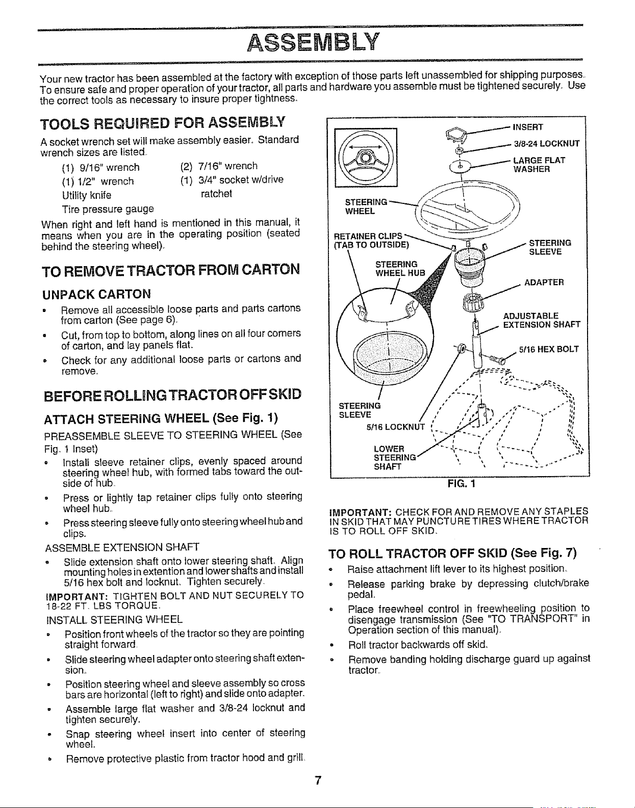
ATTACH STEERING WHEEL (See Fig. 1)
PREASSEMBLE SLEEVE TO STEERING WHEEL (See
Fig° 1 Inset)
o install sleeve retainer clips, evenly spaced around
steering wheel hub, with formed tabs toward the out-
side of hub.
- Press or lightly tap retainer clips fully onto steering
wheel hub,.
• Press steering sleeve fully onto steering wheel hub and
clips.
ASSEMBLE EXTENSION SHAFT
= Slide extension shaft onto lower steering shaft° Align
mounting holes in extention and _owershafts and instatl
5/!6 hex bolt and IocknuL Tighten securely.
IMPORTANT: TIGHTEN BOLT AND NUT SECURELY TO
18-22 FT. LBS TORQUE.
INSTALL STEERING WHEEL
• Position front wheels of the tractor so they are pointing
straight forward
• Slide steering wheel adapter onto steering shaft exten-
sion,
• Position steering wheel and sleeve assembly so cross
bars are horizontal (left to right) and slide onto adapter.
- Assemble large flat washer and 3/8-24 Iocknut and
tighten securely.
,, Snap steering wheel insert into center of steering
wheel..
o Remove protective plastic from tractor hood and grill,
LARGE FLAT
WASHER
WHEEL
('TABTO OUTSIDE)
FIG, 1
IMPORTANT: CHECK FOR AND REMOVE ANY STAPLES
IN SKID THAT MAY PUNCTURE TIRES WHERE TRACTOR
tS TO ROLL OFF SKID.
TO ROLL TRACTOR OFF SKiD (See Fig. 7)
o Raise attachment lift lever to its highest position,
o Release parking brake by depressing clutch/brake
pedal.
o Place freewheel control in freewheeling position to
disengage transmission (See "TO TRANSPORT" in
Operation section of this manual),
- Roll tractor backwards off skid,
= Remove banding holding discharge guard up against
tractor,.
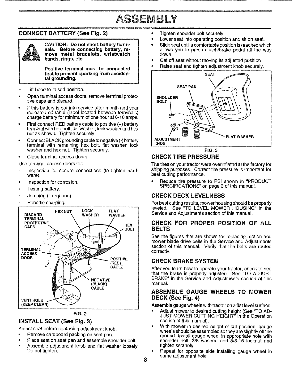
CONNECT BATTERY (See Fig. 2)
CAUTION: Do not short battery termi-
nals. Before connecting battery, re-
move metal bracelets, wristwatch
bands, rings, etc.
Positive terminal must be connected
first to prevent sparking from acciden-
tal grounding°
- Lift hood to raised position.
o Open terminal access doors, remove terminal protec-
tive caps and discard..
° tf this battery is put into service after month and year
indicated on label (label located between terminals)
charge battery for minimum of one hour at 6-10 amps.
= First connect RED battery cable to positive (+) battery
terminal with hex bolt, ftat washer, lockwasher and hex
nut as shown., Tighten securely.
° Connect BLACK grounding cable to negative (-) battery
terminal with remaining hex bolt, flat washer, lock
washer and hex nuL Tighten securely°
• Close terminal access doorsv
Use terminal access doors for:
° Inspection for secure connections (to tighten hard-
ware),,
* Inspection for corrosion.
o Testing battery.
= Jumping (if required).
o Periodic charging_
HEX NUT
DISCARD
TERMINAL
PROTECTIVE
CAPS _
TERMINAL "'"
ACCESS
DOOR ;' _.'_"_
VENT HOLE _ _ ._ j
(KEEP CLEAN
LOCK FLAT
WASHER WASHER
HEX
-BOLl"
POSITIVE
(RED)
CABLE
NEGATIVE
(BLACK)
CABLE
FIG. 2
INSTALL SEAT (See Fig. 3)
Adjust seat before tightening adjustment knob.
= Remove cardboard packing on seat pan,,
o Place seat on seat pan and assemble shoulder bolt.
° Assemble adjustment knob and flat washer Ioosely_
Do not tighten°
o Tighten shoulder bolt securely,
o Lower seat into operating position and sit on seat.
• Slide seat until a comfortable position is reached which
allows you to press clutch!brake pedal all the way
down°
° Get off seat without moving its adjusted position_
• Raise seat and tighten adjustment knob securely.
SEAT
SEAT PAN
SHOULDER
BOLT
ADJUSTMENT
KNOB
FLAT WASHER
FIG, 3
CHECK TIRE PRESSURE
The tires on your tractor were overinflated at the factory for
shipping purposes. Correct tire pressure is important for
best cutting performance.
o Reduce tire pressure to PSI shown in "PRODUCT
SPECIFICATIONS" on page 3 of this manual
CHECK DECK LEVELNESS
For best cutting results, mower housing should be properly
teveled_ See 'q-O LEVEL MOWER HOUSING" in the
Service and Adjustments section of this manual.
CHECK FOR PROPER POSITION OF ALL
BELTS
See the figures that are shown for replacing motion and
mower bfade drive belts in the Service and Adjustments
section of this manual Verify that the belts are routed
correctly°
CHECK BRAKE SYSTEM
After you learn how to operate your' tractor, check to see
that the brake is properly adjusted, See "TO ADJUST
BRAKE" in the Service and Adjustments section of this
manual.
ASSEMBLE GAUGE WHEELS TO MOWER
DECK (See Fig. 4)
Assemble gauge wheels with tractor on a flat level surface.
. Adjust mower to desired cutting height (See '_FOAD-
JUST MOWER CUTTING HEIGHT in the Operation
section of this manual).
o With mower in desired height of cut position, gauge
wheels should be assembled so they are slightly off the
ground° install gauge wheel in appropriate hole with
shoulder bolt, 3/8 washer, and 3/8-16 Iocknut and
tighten securely.
. Repeat for opposite side installing gauge wheel in
same adjustment ho!_
A$$ENBLY
_1 ii,m iHiim ,11,11
GAUGE WHEEL
MOUNTING
BRACKET
3/8WASHER SHOULDER
GAUGE WHEEL
FIG. 4
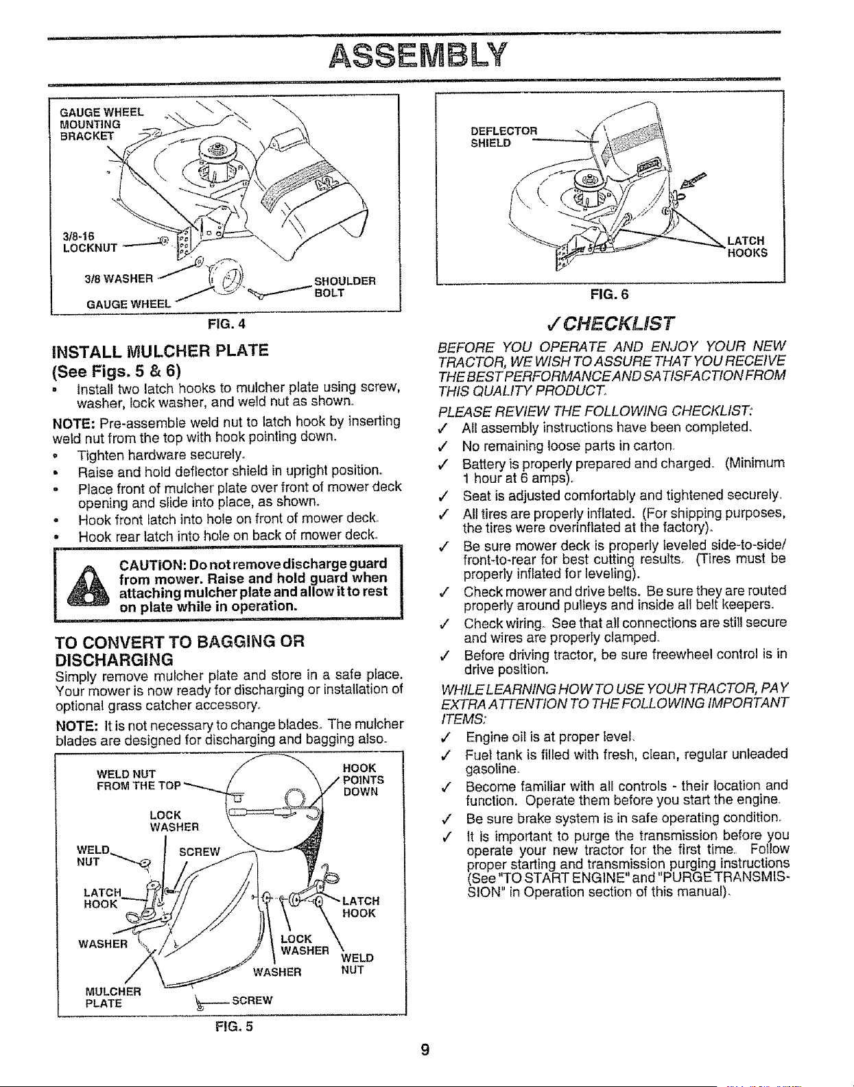
iNSTALL MULCHER PLATE
(See Figs. 5 & 6)
. Install two latch hooks to mulcher plate using screw,
washer, lock washer, and weld nut as shown,,
NOTE: Pre-assemble weld nut to latch hook by inserting
weld nut from the top with hook pointing down.
, Tighten hardware securely°
• Raise and hold deflector shield in upright position,,
o Place front of mulcher plate over front of mower deck
opening and slide into place, as shown.,
° Hook front latch into hole on front of mower deck_
= Hook rear latch into hole on back of mower deck.
, i,,,, i,,,11 ,,i ,,,,,i,
!_ CAUTION: Do not remove discharge guard
from mower. Raise and hold guard when
attaching mulcher plate and allow it to rest
on plate while in operation.
................ i1,, i i,i1,11_
TO CONVERT TO BAGGING OR
DISCHARGING
Simply remove mulcher plate and store in a safe place.
Your mower is now ready for discharging or installationof
optional grass catcher accessory.
NOTE: It is not necessary to change blades. The mulcher
blades are designed for discharging and bagging alsoo
WELD NUT HOOK
FROM THE DOWN
LOCK
WASHER
HOOK
WASHER LOCK
WASHER
HOOK
WELD
WASHER NUT
MULCHER
PLATE _----SCREW
FIG. 5
DEFLECTOR
SHIELD
LATCH
HOOKS
FIG. 6
,/CHECKLIST
BEFORE YOU OPERATE AND ENJOY YOUR NEW
TRACTOR, WE WISH TO ASSURE THA T YOU RECEIVE
THE BEST PERFORMANCE AND SA TtSFA CTION FROM
THIS QUALITY PRODUCT,
PLEASE REVIEW THE FOLLOWING CHECKLIST';
,/ All assembly instructions have been completed.
¢" No remaining loose parts in carton.
¢" Battery is properly prepared and charged. (Minimum
1 hour at 6 amps)..
,/ Seat is adjusted comfortably and tightened securely,
•/ All tires are properly inflated. (For shipping purposes,
the tires were overinflated at the factory)°
V Be sure mower deck is properly leveled side-to-side/
front-to-rear for best cutting results. (Tires must be
properly inflated for leveling).
¢ Check mower and drive belts. Be sure they are routed
properly around pulleys and inside all belt keepers.
,/ Check wiring_ See that all connections are still secure
and wires are properly clamped..
#' Before driving tractor, be sure freewheel control is in
drive position.
WHILELEARNING HOWTO USE YOUR TRACTOR, PAY
EXTRA ATTENTION TO THE FOLLOWING IMPORTANT
ITEMS:
¢" Engine oil is at proper level,
,/ Fuel tank is filled with fresh, clean, regular unleaded
gasolineo
,/ Become familiar with all controls - their location and
function. Operate them before you start the engine,
¢ Be sure brake system is in safe operating condition_
¢ It is important to purge the transmission before you
operate your new tractor for the first time, Follow
proper starting and transmission purging instructions
(See "TO START ENGINE" and "PURGE TRANSMIS-
SION" in Operation section of this manual).
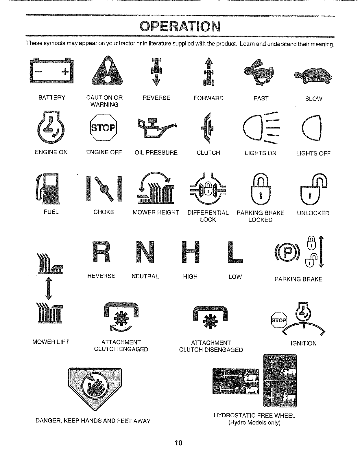
OPERATmON
These symbols may appear on your tractor or in literature supplied with the producL Learn and understand their meaning
BATTERY CAUTION OR REVERSE FORWARD FAST SLOW
WARNING
ENGINE ON ENGINE OFF OIL PRESSURE CLUTCH LIGHTS ON LIGHTS OFF
FUEL CHOKE
MOWER HEIGHT DIFFERENTIAL PARKING BRAKE UNLOCKED
LOCK LOCKED
MOWER LIFT
REVERSE NEUTRAL
ATTACHMENT
CLUTCH ENGAGED
L
HIGH LOW
ATTACHMENT
CLUTCH DISENGAGED
PARKING BRAKE
IGNITION
DANGER, KEEP HANDS AND FEET AWAY
HYDROSTATIC FREEWHEEL
(Hydro Modelsonly)
10
,,i .... i
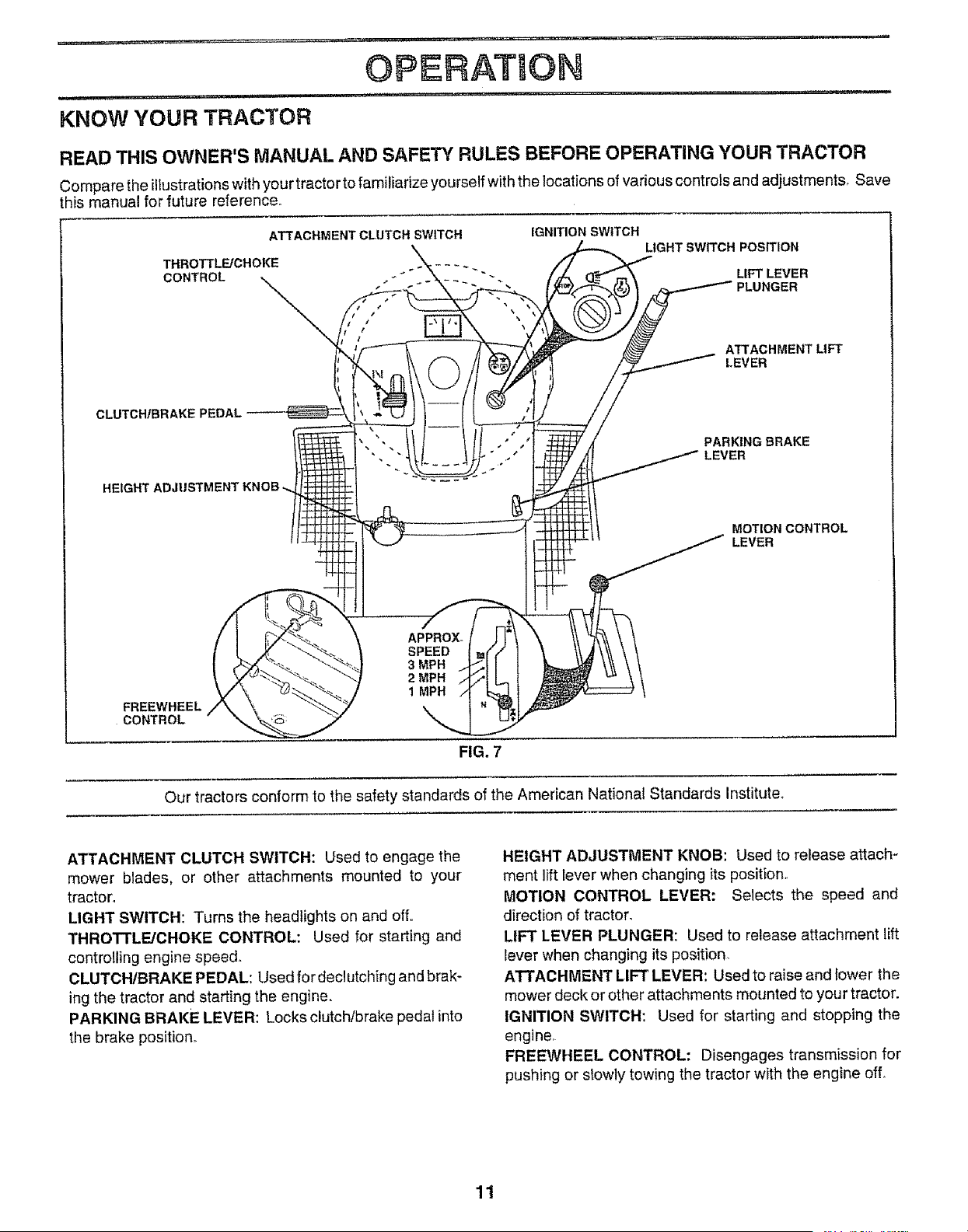
KNOW YOUR TRACTOR
OPERATUON
,iii,,,,,i, _ ............
READ THIS OWNER'S MANUAL AND SAFETY RULES BEFORE OPERATING YOUR TRACTOR
Compare the illustrations with your tractor to familiarize yourself with the locations of various controls and adjustments_ Save
his manual for future reference.
ATTACHMENT CLUTCH SWITCH
THROTTLE/CHOKE
CONTROL
IGNITION SWITCH
LIGHT SWITCH POSITION
LIFT LEVER
ATTACHMENT LIFT
LEVER
CLUTCH/BRAI'
HEIGHT ADJ
PARKING BRAKE
LEVER
MOTIONCONTROL
LEVER
FREEWHEEL
CONTROL
FIG. 7
Our tractors conform to the safety standards of the American National Standards Institute_
ATTACHMENT CLUTCH SWITCH: Used to engage the
mower blades, or other attachments mounted to your
tractor°
LIGHT SWITCH: Turns the headlights on and off.
THROTTLE/CHOKE CONTROL: Used for starting and
controlling engine speed.
CLUTCH/BRAKE PEDAL: Used for declutching and brak-
ing the tractor and starting the engine.
PARKING BRAKE LEVER: Locks clutch!brake pedal into
the brake position°
HEIGHT ADJUSTMENT KNOB: Used to release attach-
ment lift lever when changing its position.
MOTION CONTROL LEVER: Selects the speed and
direction of tractor.
LIFT LEVER PLUNGER: Used to release attachment lift
lever when changing its position_
ATTACHMENT LIFT LEVER: Used to raise and fower the
mower deck or other attachments mounted to your tractor.
IGNITION SWITCH: Used for starting and stopping the
engine,
FREEWHEEL CONTROL: Disengages transmission for
pushing or slowly towing the tractor with the engine ofL
11
OPERATION
The operation of any tractor can result in foreign objects thrown into the eyes, which can
result in severe eye damage. Always wear safety glasses or eye shields while operating
your tractor or performing any adjustments or repairs. We recommend a wide vision
safety mask over the spectacles or standard safety glasses.
HOW TO USE YOUR TRACTOR
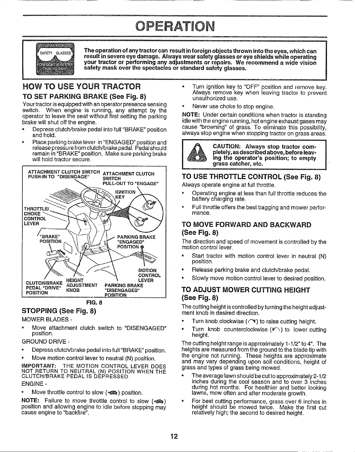
TO SET PARKING BRAKE (See Fig. 8)
Your tractor isequipped with an operator presence sensing
switch. When engine is running, any attempt by the
operator to leave the seat without first setting the parking
brake will shut off the engine.
= Depress clutch_rake pedal into full "BRAKE" position
and hold.
= Place parking brake lever in "ENGAGED" position and
release pressure from clutch!bral(e pedal Pedalsheutd
remain in "BRAKE" position+ Make sure parking brake
wilt hold tractor secure.
ATTACHMENT CLUTCH SWITCH ATTACHMENT CLUTCH
PUSH-IN TO "DISENGAGE" SWITCH
PULL-OUT TO "ENGAGE"
IGNITION
HEIGHT
CLUTCH/BRAKE ADJUSTMEN3"
PEDAL "DRIVE" KNOB
POSITION
FIG. 8
STOPPING (See Fig. 8)
MOWER BLADES -
MO_ON
CONTROL
LEVER
PARKING BRAKE
"DISENGAGED"
POSITION
= Move attachment clutch switch to "DISENGAGED"
position.
GROUND DRIVE +
= Depress clutch/brake pedal into full "BRAKE" position.
= Move motion control lever to neutral (N) position.
IMPORTANT: THE MOTION CONTROL LEVER DOES
NOT RETURN TO NEUTRAL (N) POSITION WHEN THE
CLUTCH/BRAKE PEDAL IS DEPRESSED.
ENGINE -
• Move throttle control to slow (,_,) position.
NOTE: Failure to move throttle control to slow (,_)
position and allowing engine to idle before stopping may
cause engine to "backfire".
= Turn ignition key to "OFF" position and remove key.
Always remove key when leaving tractor to prevent
unauthorized use_
o Never use choke to stop engine°
NOTE: Under' ce+tain conditions when tractor is standing
idle with the engine running, hot engine exhaust gases may
cause "browning" of grass. To eliminate this possibility,
always stop engine when stopping tractor on grass areas.
pletely, as described above, before leav-
ing the operator's position; to empty
grass catcher, etc,
TO USE THROTTLE CONTROL (See Fig. 8)
Always operate engine at full throttle+
= Operating engine at less than full throttle reduces the
battery charging rate.
+ Full throttle offers the best bagging and mower perfoF
manGe.
TO MOVE FORWARD AND BACKWARD
(See Fig. 8)
The direction and speed of movement is controlled by the
motion control lever+
• Start tractor with motion control lever in neutral (N)
position.
• Release parking brake and clutch/brake pedal
• Slowly move motion control lever to desired position.
TO ADJUST MOWER CUTTING HEIGHT
(See Fig. 8)
The cuttingheight iscontrolledbyturning the height adjust-
ment knob in desired direction.
o Turn knob clockwise ((_) to raise cutting height,
° Turn knob counterclockwise (F_,) to lower cutting
height°
The cutting height range is approximately 1-1/2" to 4". The
heights are measured from the ground to the blade tip with
the engine not running. These heights are approximate
and may vary depending upon soil conditions, height of
grass and types of grass being mowed.
= The average lawn should be Cutto approximately 2-1/2
inches during the cool season and to over 3 inches
during hot months. For healthier' and better looking
lawns, mow often and after moderate growth+
o For best cutting performance, grass over 6 inches in
height should be mowed twice. Make the first cut
relatively high; the second to desired height°
12
OPERATUON
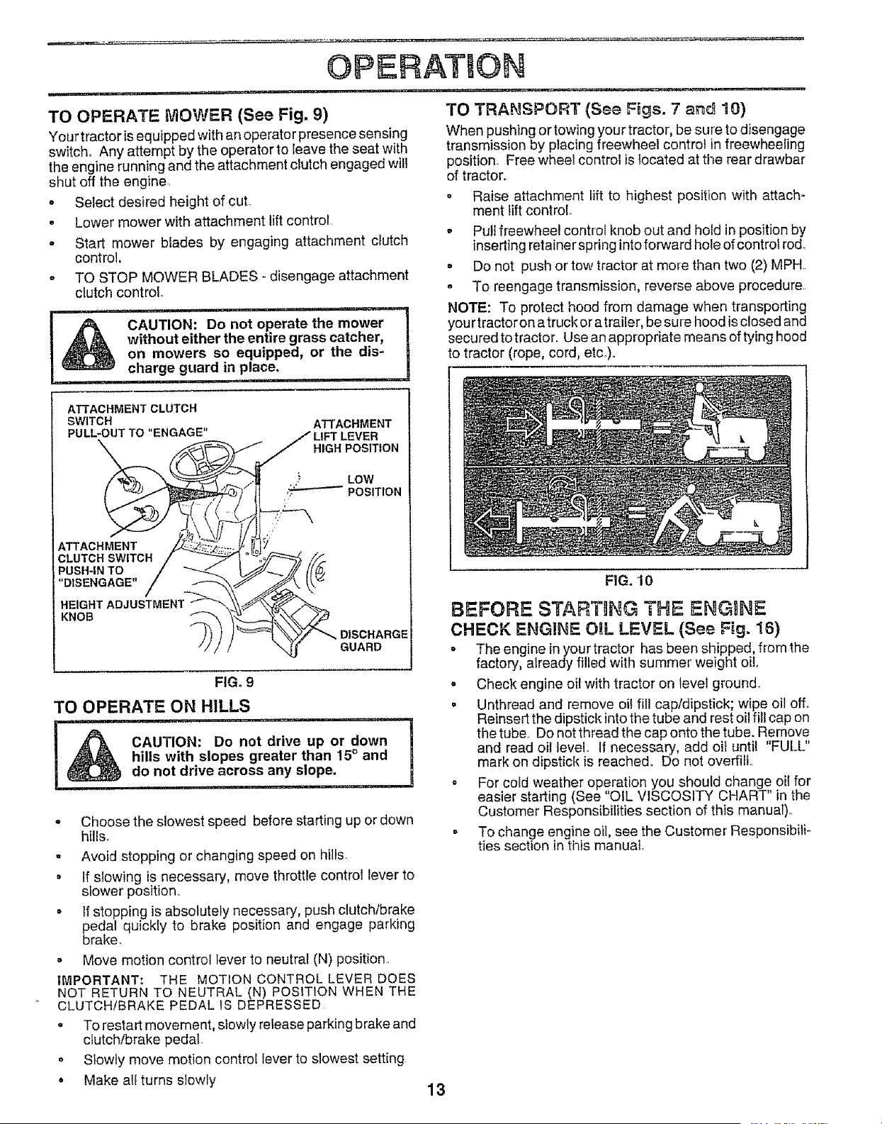
TO OPERATE MOWER (See Fig. 9)
Your tractor is equipped with an operator presence sensing
switch_ Any attempt by the operator to leave the seat with
the engine running and the attachment clutch engaged will
shut off the engine.
, Select desired height of cut.
o Lower mower with attachment lift control
• Start mower blades by engaging attachment clutch
control.
° TO STOP MOWER BLADES - disengage attachment
clutch control.
i, nl ..... U l nU,lllllll,
l& CAUTION: Do not operate the mower
without either the entire grass catcher,
on mowers so equipped, or the dis-
charge guard in place.
i i ,Ul ii, ,,i
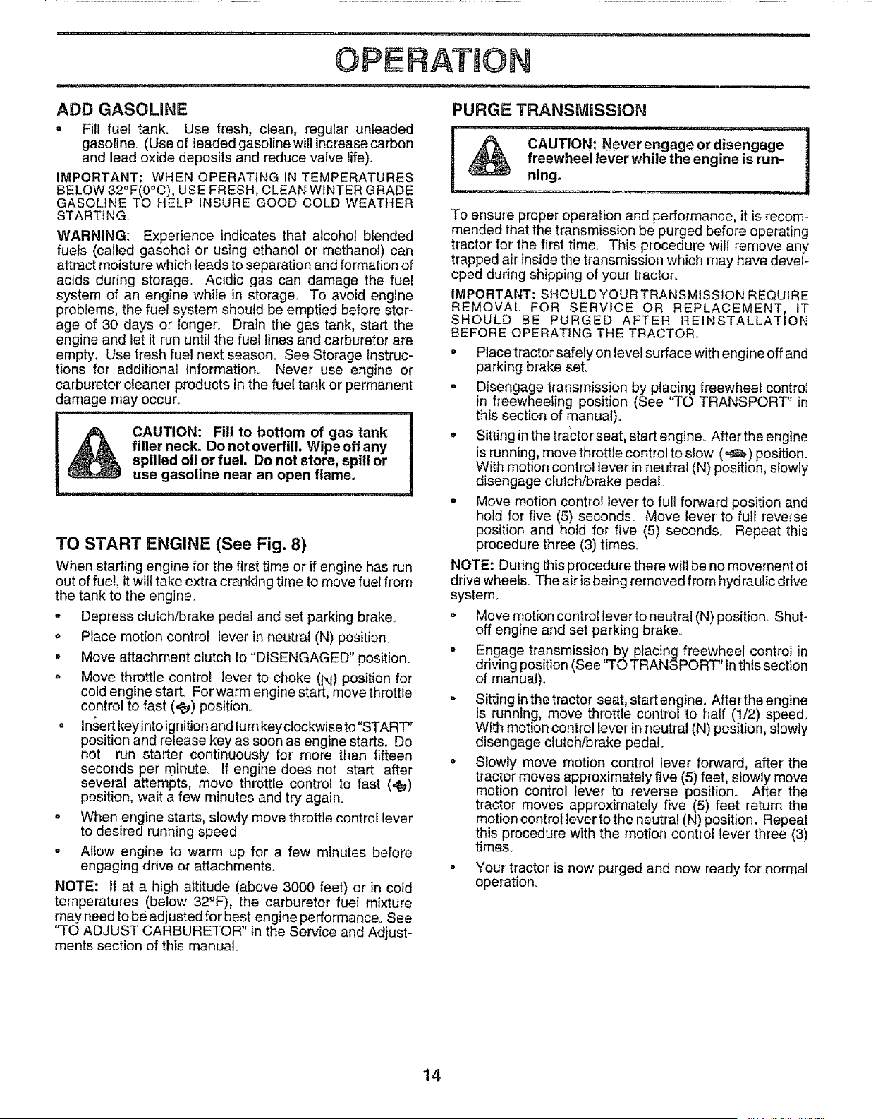
TO TRANSPORT (See Figs. 7 and 10)
When pushing or towing your tractor, be sure to disengage
transmission by placing freewheel control in freewheeling
position Free wheel control is located at the rear drawbar
of tractor.
° Raise attachment lift to highest position with attach-
ment lift control.
, Pull freewheel control knob out and hold in position by
inserting retainer spring into forward hole of control rod°
o Do not push or tow tractor at more than two (2) MPH.
- To reengagetransmission, reverse above procedure
NOTE: To protect hood from damage when transporting
your tractor on atruck or atrailer, be sure hood is closed and
secured totractor. Use an appropriate means of tying hood
to tractor (rope, cord, etCo)o
ATTACHMENT CLUTCH
SWITCH
PULL, OUT TO "ENGAGE"
CLUTCHSWITCHf
PUSH-INTO /
"DISENGAGE" /
HEIGHT ADJUSTMENT/
KNOB _,_
ATTACHMENT
__ LIFT LEVER
• HIGH POSITION
LOW
/ \ jr GUARD
FIG. 9
TO OPERATE ON HILLS
i& CAUTION: Do not drive up or down
hills with slopes greater than 15° and
do not drive across any slope.
i ,u , ,H
• Choose the slowest speed before starting up or down
hills.
- Avoid stopping or changing speed on hills.
• If slowing is necessary, move throttle control lever to
slower position..
° If stopping is absolutely necessary, push clutchtbrake
_edal quickly to brake position and engage parking
rake.
- Move motion control lever to neutral (N) position.
IMPORTANT: THE MOTION CONTROL LEVER DOES
NOT RETURN TO NEUTRAL (N) POSITION WHEN THE
CLUTCH/BRAKE PEDAL 1SDEPRESSED
° To restart movement, slowly release parking brake and
clutch/brake pedal
• Slowly move motion control lever to slowest setting
, Make all turns slowly
13
FIG. 10
BEFORE STARTING THE ENGINE
CHECK ENGINE OtL LEVEL (See Fig. 16)
= The engine inyour tractor has been shipped, from the
factory, already filled with summer weight oil.
• Check engine oi! with tractor on level ground.
° Unthread and remove oil fill cap/dipstick; wipe oil off.
Reinsert the dipstick intothe tube and rest oil fill cap on
the tube. Do not thread the cap onto the tube. Remove
and read oil level. If necessary, add oil until "FULL"
mark on dipstick is reached, Do not overfill.
- For cold weather operation you should change oil for
easier starting (See "OIL VISCOSITY CHART" in the
Customer Responsibilities section of this manual).
• To change engine oil, see the Customer Responsibili-
ties section in tinis manual.
OPERATION
ADD GASOLINE
= Fill fuel tank. Use fresh, clean, regular unleaded
gasoline. (Use of leaded gasoline wilt increase carbon
and lead oxide deposits and reduce valve life).
IMPORTANT: WHEN OPERATING IN TEMPERATURES
BELOW 32°F(0°C), USE FRESH, CLEAN WINTER GRADE
GASOLINE TO HELP INSURE GOOD COLD WEATHER
STARTING.
WARNING: Experience indicates that alcohol blended
fuels (called gasohol or' using ethanol or' methanol) can
attract moisture which leads to separation and formation of
acids during storage.. Acidic gas can damage the fuel
system of an engine while in storage. To avoid engine
problems, the fuel system should be emptied before stor-
age of 30 days or ionger. Drain the gas tank, start the
engine and let it run until the fuel lines and carburetor are
empty, Use f_esh fuel next season. See Storage Instruc-
tions for additional information° Never use engine or
carburetor cleaner products in the fuel tank or permanent
damage may occur.
...... i ..............................
CAUTION: Fill to bottom of gas tank
filler neck, Do not overfill. Wipe off any
spilled oil or fuel. Do not store, spill or
use gasoline near an open flame,
TO START ENGINE (See Fig. 8)
When starting engine for the first time or ifengine has run
out offuel, itwiiftake extra cranking time to move fuel from
the tank to the engine.
° Depress clutch/brake pedal and set parking braker
o Place motion controI lever in neutral (N) position.
o Move attachment clutch to "DISENGAGED" position.
o Move throttle control lever to choke (1\1)position for
cold engine start_ For'warm engine start, move throttle
control to fast (,_) position,.
= In.sertkey into ignition andtum key c!ockwise to"START"
position and release key as soon as engine starts. Do
not run starter continuously for' more than fifteen
seconds per minute. If engine does not start after
several attempts, move throttle control to fast (,_)
position, wait a few minutes and try again_
o When engine starts, slowly move throttle control lever
to desired running speed
= Allow engine to warm up for a few minutes before
engaging drive or attachments.
NOTE: If at a high altitude (above 3000 feet) or in cold
temperatures (below 32°F), the carburetor fuel mixture
may need to be adjusted for best engine performance_ See
"TO ADJUST CARBURETOR" in the Service and Adjust-
ments section of this manual
PURGE TRANSIVIISSION
!
To ensure proper operation and performance, it is recom-
mended that the transmission be purged before operating
tractor for the first time This procedure will remove any
trapped air inside the transmission which may have devel-
oped during shipping of your' tractor.
IMPORTANT: SHOULD YOUR TRANSMISSION REQUIRE
REMOVAL FOR SERVICE OR REPLACEMENT, IT
SHOULD BE PURGED AFTER REINSTALLATION
BEFORE OPERATING THE TRACTOR..
. Place tractor safely on level surface with engine off and
parking brake set.
- Disengage transmission by placing freewheel control
in freewheeling position (See 'TO TRANSPORT" in
this section of manual).
= Sitting inthe trac:tor seat, start engine. After the engine
is running, move throttle control to slow (._.) position.
With motion control lever in neutral (N) position,slowly
disengage clutch/brake pedal
. Move motion control lever to full forward position and
hold for five (5) seconds. Move lever to full reverse
position and hold for five (5) seconds Repeat this
procedure three (3) times.
NOTE: During this procedure there will be no movement of
drive wheels. The air is being removed from hydraulic drive
system.
• Move motion control lever to neutrat (N) position. Shut-
off engine and set parking brake.
= Engage transmission by placing freewheel control in
driving position (See ''TO TRANSPORT" inthis section
of manual)°
• Sittinginthetractor seat startengine. After the engine
is running, move throttle control to half (1/2) speed°
With motion control lever' in neutral (N) position, slowly
disengage clutch/brake pedal
° Slowly move motion control lever forward, after the
tractor moves approximately five (5) feet, slowly move
motion control lever to reverse position. After' the
tractor moves approximately five (5) feet return the
motion control lever to the neutral (N) position. Repeat
this procedure with the motion control lever three (3)
times.
= Your tractor is now purged and now ready for normal
operation.
14
OPERATION
MOWING TIPS
o Tire chains cannot be used when the mower housing
is attached to tractor°
o Mower should be properly leveled for best mowing
performance See'%O LEVEL MOWER HOUSING" in
the Service and Adjustments section of this manual.
= The left hand side of mower should be used for trim-
mingo
o Drive so that clippings are discharged onto the area
that has been cut. Have the cut area to the right of the
machine. This will result in a more even distribution of
clippings and more uniform cutting.
° When mowing large areas, start by turning to the right
so that clippings will discharge away from shrubs,
fences, driveways, etco After one or two rounds, mow
in the opposite direction making left hand turns until
finished (See Fig. 11 ).
• tf grass is extremely tall, it should be mowed twice to
reduce load and possible fire hazard from dried clip-
pings. Make first cut relatively high; the second to the
desired height°
• Do not mow grass when it is wet. Wet grass will plug
mower and leave undesirable clumps. Allow grass to
dry before mowing.
° Always operate engine at full throttle when mowing to
assure better mowing performance and proper dis-
charge of material. Regulate ground speed by select-
ing a low enough gear to give the mower cutting
performance as well as the quality of cut desired..
° When operating attachments, select a ground speed
that wilf suit the terrain and give best performance of
the attachment being used.
f
]
MULCHING MOWING TIPS
IMPORTANT: FOR BEST PERFORMANCE, KEEP
MOWER HOUSING FREE OF BUILT-UP GRASS AND
TRASH. CLEAN AFTER EACH USE
. The special mulching blade wilt recut the grass clip-
pings many times and reduce them in size so that as
they fatl onto the lawn they will disperse into the grass
and not be noticed. Also, the mulched grass wil!
biodegrade quickly to provide nutrients for the lawn.
Always muich with your highest engine (blade) speed
as this will provide the best recutting action of the
blades.
• Avoid cutting your lawn when it iswet. Wet grass tends
to form clumps and interferes with the mulching action.
The best time to mow your lawn is the early afternoon..
At this time the grass has dried and the newly cut area
will not be exposed to the direct sun.
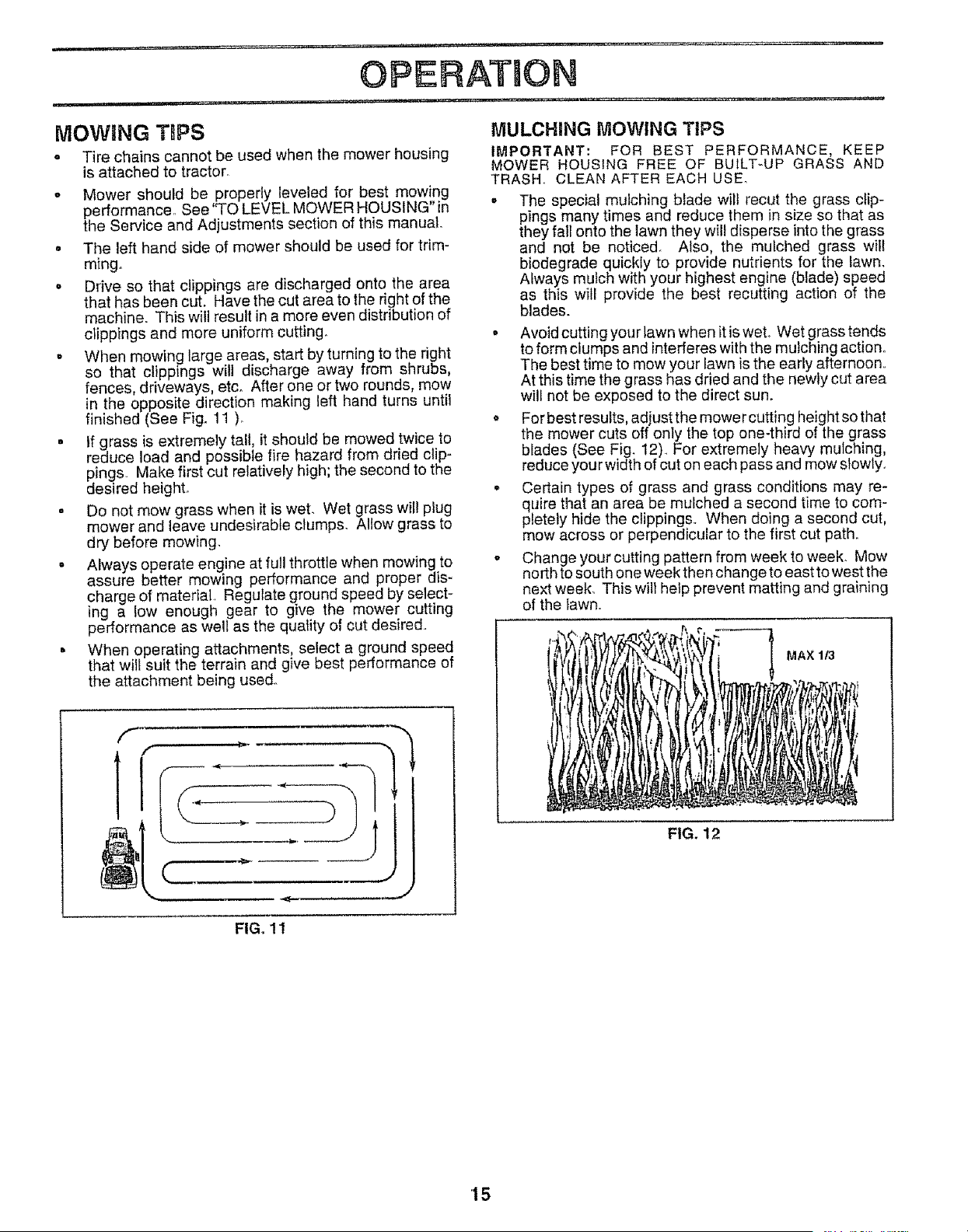
o For best results, adjust the mower cutting heightso that
the mower cuts off only the top one-third of the grass
blades (See Fig. 12). For extremely heavy mulching,
reduce you rwidth of cut on each pass and mow slowlyo
• Certain types of grass and grass conditions may re-
quire that an area be mulched a second time to com-
pletely hide the clippings.. When doing a second cut,
mow across or perpendicular to the first cut path.
- Change your cutting pattern from week to week. Mow
north tosouth one week then change to east to west the
next week_ This will help prevent matting and graining
of the lawn.
MAX 1/3
FIG. 12
FIGo 11
'15
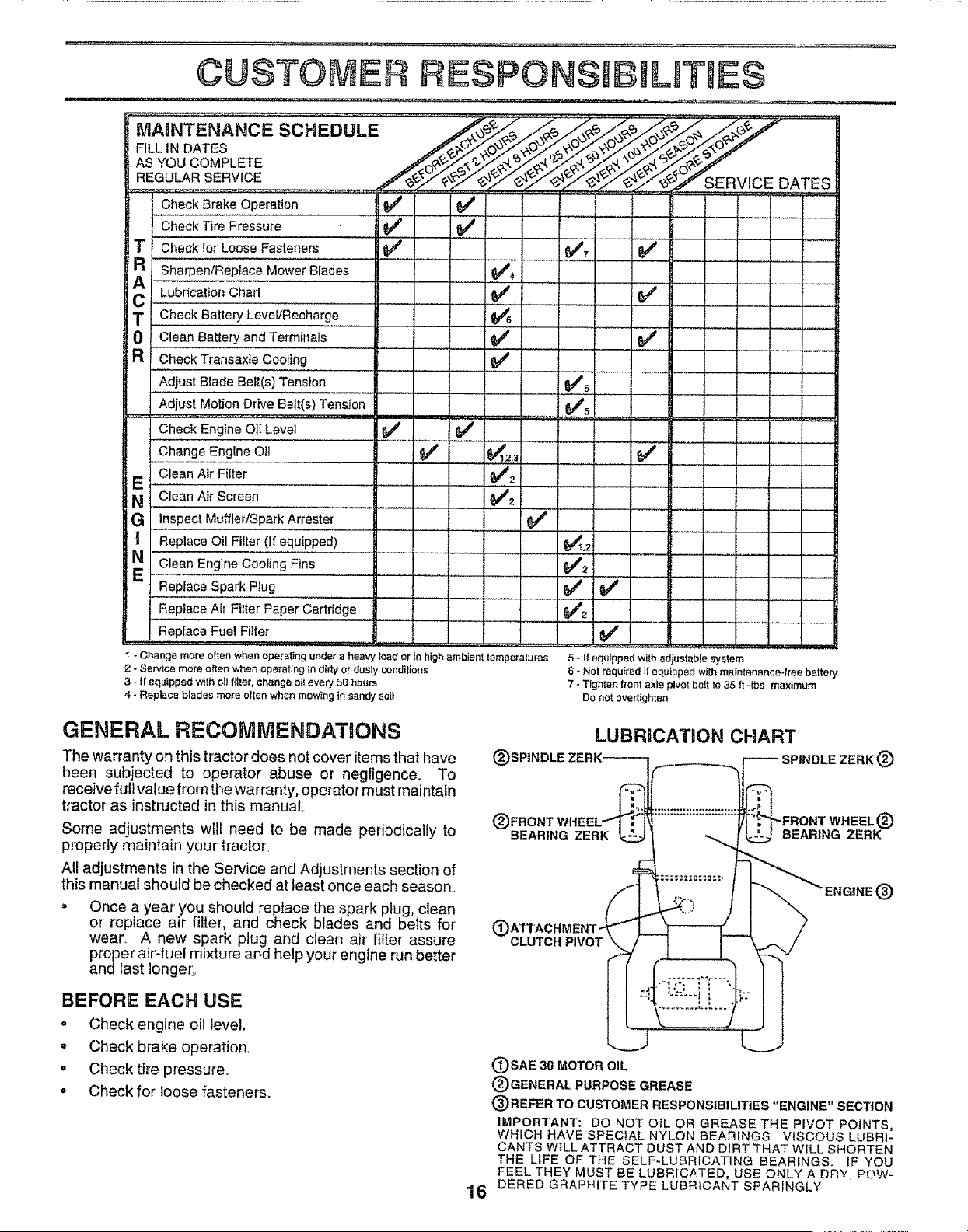
CUSTO#ER ESPONSHB LmT ES
MA,.TE.A.CESCHEDULE ..........
FILL iN DATES /_5_/_>,_/_. _"_0_ _
REGU_R SERV!CE....................... /_'.z_. "_'_._S EBv !c E DATES
CheckBrakeOperation _#_ 6_'
J J
v' j
v' v'
_6'
v'5 J
........ i ......
V' J,.2.3 v'
..... _2
....!V'2
e,'
e,'2
.... I .......
v' v'
CheckTire Pressure
T Checkfor LooseFasteners
R Sharpen/ReplaceMowerBlades
_ Lubrication Chart
T CheckBattery Level/Recharge
0 Clean Battery andTerminals
R'
ChockTransaxleCooling
Adjust Blade Belt(s) Tension
Adjust Motion Drive Belt(s) Tension
Check Engine Oii Level
ChangeEngineOil
CleanAirFilter
E
N CleanAirScreen
G inspectMuffler/SparkArrester
] Replace OilFilter(If equipped)
N CleanEngineCoolingFins
ReplaceSparkPlug
ReplaceAir FitterPaperCartridge
ReplaceFuelFilter
5 - It equipped with adjustable system
6 - Nat requited if equipped wi{h maintenance-free battery
7 - Tighten trent axle pIvo! bait _a 35 ft -ibs maximum
Do not overtighter_
t -Change more often when operating under a heavy load or in high ambient tempetalures
2 - Servlce more often when operating in dirb/or dusiy cunditions
3 - I! equipped with oil filter, change o}l every 50 hours
4 - Replace blades more el'ten when mowing in sandy suit
GENERAL RECOMMENDATIONS
The warranty on this tractor does not cover items that have
been subjected to operator abuse or negligence. To
receive full value from the warranty, operator must maintain
tractor as instructed in this manual
Some adjustments will need to be made periodically to
properly maintain your tractor.
All adjustments in the Service and Adjustments section of
this manual should be checked at least once each season.
,, Once a year you should replace the spark plug, clean
or' replace air filter, and check blades and belts for
wear_ A new spark plug and clean air' filter assure
proper air-fuel mixture and help your engine run better
and last Ionget:o
®
LUBRiCATiON CHART
SPINDLE ZERK ®
_FRONT WHEEL®
(_)BEAR1NG ZERK BEARING ZERK
CLUTCH PIVOT
®
BEFORE EACH USE
o Check engine oil level.
= Check brake operation,
• Check tire pressure.
o Check for loose fasteners.
(_)SAE 30 MOTOR OIL
®GENERAL PURPOSE GREASE
®REFER TO CUSTOMER RESPONSIBILITIES "ENGINE" SECTION
IMPORTANT: DO NOT alL OR GREASE THE PIVOT POINTS,
WHICH HAVE SPECIAL NYLON BEARINGS VISCOUS LUBRI-
CANTS WiLL ATTRACT DUST AND DIRT THAT WiLL SHORTEN
THE LIFE OF THE SELF-LUBRICATING BEARINGS. tF YOU
FEEL THEY MUST BE LUBRICATED, USE ONLY A DRY, PaW-
16 DERED GRAPHITE TYPE LUBRICANT SPARINGLY
TRACTOR
Always observe safety rules when performing any mainte-
nance,
BRAKE OPERATION
tf tractor requires more than six (6) feet stopping distance
at high speed in highest gear, then brake must be adjusted.
(See "TO ADJUST BRAKE" in the Service and Adjust-
ments section of this manual)
TIRES
• Maintain proper air pressure in alt tires (See "PROD-
UCT SPECIFICATIONS" on page 3 of this manual).
- Keep tires free of gasoline, oil, or insect control chemi-
cals which can harm rubber.
° Avoid stumps stones, deep ruts, sharp objects and
other hazards that may cause t re damage,
BLADE CARE
For best results mower blades must be kept sharp. Re-
place bent or damaged blades°
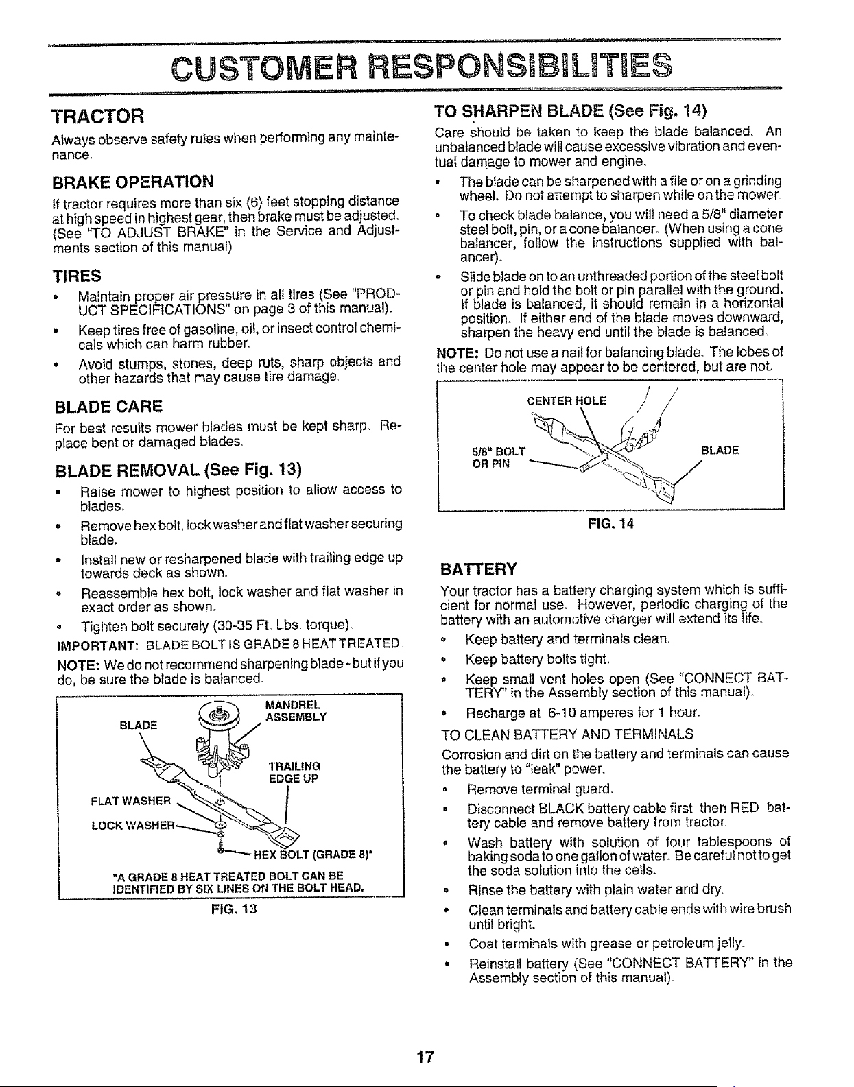
BLADE REMOVAL (See Fig. 13)
. Raise mower to highest position to allow access to
blades.
o Remove hex bolt, Iockwasher and flat washer securing
blade_
- Install new or resharpened blade with trai_ing edge up
towards deck as shown
- Reassemble hex bolt, lock washer and flat washer in
exact order as shown.
• Tighten bolt securely (30-35 FL Lbs. torque).
IMPORTANT: BLADE BOLT ISGRADE 8 HEATTREATED,
NOTE: We do net recommend sharpening blade- but ifyou
do, be sure the blade is balanced,
BLADE
MANDREL
ASSEMBLY
FLAT WASHER
TRAILING
EDGE UP
/
HEXBOLT(GRADE 8)*
*A GRADE 8 HEAT TREATED BOLTCAN BE
IDENTIFIED BY SIXLINES ONTHEBOLTHEA_
FIG. 13
ESPONS B L TUES
TO SHARPEN BLADE (See Fig. !4)
Care should be taken to keep the blade balanced.. An
unbalanced blade will cause excessive vibration and even-
tuai damage to mower and engine.
° The blade can be sharpened with afite or on a grinding
wheel. Do not attempt to sharpen while onthe mower_
• To check blade ba]ance, you will need a 5/8" diameter
steel bolt, pin, or a cone baiancer. (When using a cone
balancer, follow the instructions supplied with bal-
ancer).
o Slide blade on to an unthreaded portion ofthe steel bolt
or pin and hotd the bolt or pin parallel with the ground,
If blade is balanced, it should remain in a horizontal
position. If either end of the blade moves downward,
sharpen the heavy end until the blade is balanced
NOTE: Do not use a nail for balancing blade. The lobes of
the center hole may appear to be centered, but are not.
CENTER HOLE /
FIG, 14
BATTERY
Your tractor has a battery charging system which is suffF
cient for normal use. However, periodic charging of the
battery with an automotive charger will extend its life,,
, Keep battery and terminals clean.
• Keep battery bolts tight,
• Keep small vent holes open (See "CONNECT BAT-
TERY" in the Assembly section of this manua0,.
o Recharge at 6-10 amperes for 1 hour°
TO CLEAN BATTERY AND TERMINALS
Corrosion and dirt on the battery and terminals can cause
the battery to "leak" power
• Remove terminal guard,
° Disconnect BLACK battery cable first then RED bat-
tery cable and remove battery from tractor,
° Wash battery with solution of four tablespoons of
baking soda to one gallon ofwater, Be careful not to get
the soda solution into the ceils.
• Rinse the battery with plain water and dry,
° Clean terminals and battery cable ends with wire brush
until bright.
o Coat terminals with grease or petroleum jelly.
• Reinstall battery (See "CONNECT BATTERY" in the
Assembly section of this manual)
17
CUSTO . E£ RESPONGIBJLWT EG
TRANSAXLE COOLING
The fan and cooling fins of transmission should be kept
clean to assure proper' cooling.
Do not attempt to clean fan or transmission while engine is
running or while the transmission is hoL
= Inspect cooling fan to be sure fan blades are intactand
clean.
* Inspect cooling fins for dirt, grass clippings and other
materials° To prevent damage to seals, do not use
compressed air or high pressure sprayer to clean
coo_ing fins.
TRANSAXLE PUMP FLUHD
The transaxte was sealed at the factory and fluid mainte-
nance isnot required for the life of the transaxle Should the
transaxle ever' leak or' require servicing, contact your near-
est authorized service center/department.
V-BELTS
Check V-belts for deterioration and wear after 100 hours of
operation and replace if necessary, The belts are not
adjustable, Replace belts if they begin to sfip from wear.
ENGaNE
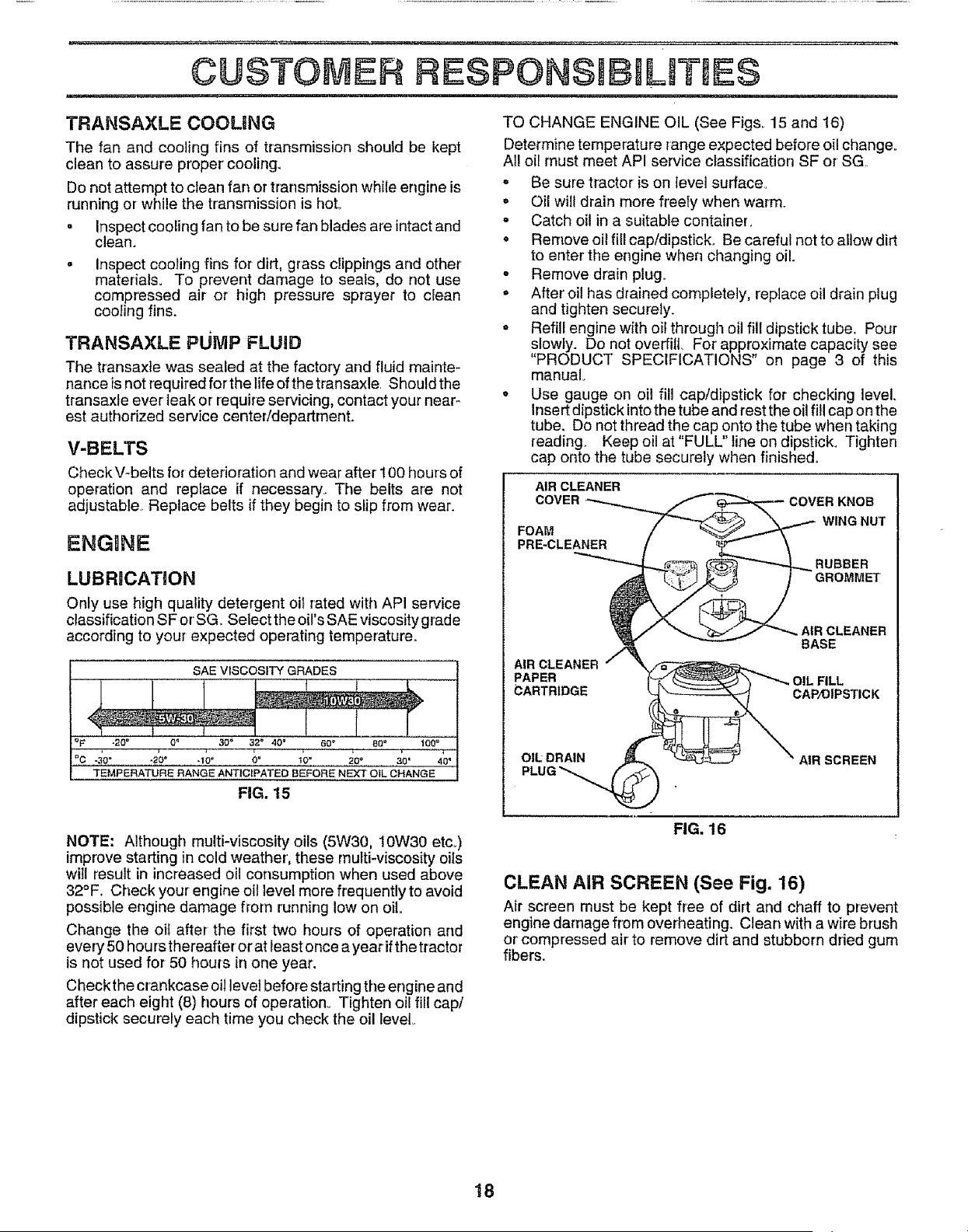
LUBRICATION
Only use high quality detergent oit rated with API service
classification SForSGo Select the oirs SAE viscosity grade
according to your expected operating temperature°
SAE VISCOSITY GRADES
"l
°C -3o_ -20° q0 _ 0° to" ,2o?.......... 30' 40"
"TEMPERATURE RANGE ANTICIPATED BEFORE NEXT OIL CHANGE
FNG,15
TO CHANGE ENGINE OIL (See Figs. 15 and 16)
Determine temperature range expected before oil change.
All oil must meet API service classification SF or SG.
• Be sure tractor is on level surface,
• Oil will drain more freeIy when warm.
. Catch oil in a suitable container,
o Remove oil fill cap/dipstick,. Be careful not to allow dirt
to enter the engine when changing oil
- Remove drain plug.
• After' oil has drained completely, replace oil drain plug
and tighten securely.
- Refill engine with oil through oil fill dipstick tube. Pour
slowly. Do not overfill For' approximate capacity see
"PRODUCT SPECIFICATIONS" on page 3 of this
manual.
• Use gauge on oil fill cap/dipstick for checking level.
Insert dipstick into the tube and test the oil fill cap on the
tube. Do not thread the cap onto the tube when taking
reading. Keep oil at "FULL" line on dipstick. Tighten
cap onto the tube securely when finished.
AIR CLEANER
COVER
FOAM
PRE-CLEANER
COVER KNOB
WING NUT
RUBBER
GROMMET
BASE
AIR CLEANER
PAPER OIL FILL
(3ARTR1DG E CAP/OIPSTIC K
OIL: DRAIN
PLUG
AIR SCREEN
NOTE: Although multi-viscosity oils (5W30, 10W30 etc,,)
improve starting in cold weather, these multi-viscosity oils
will result in increased oil consumption when used above
32°F. Check your engine oil level more frequently to avoid
possible engine damage from running low on oil.
Change the oif after the first two hours of operation and
every 50 hours thereafter or at least once a year ifthe tractor
is not used for 50 hours in one year.
Check the crankcase oil level before starting the engine and
after each eight (8) hours of operation., Tighten oil fill cap/
dipstick securely each time you check the oil level,.
FIG. 16
CLEAN AIR SCREEN (See Fig. 16)
Air screen must be kept free of dirt and chaff to prevent
engine damage from overheating. Clean with a wire brush
or'compressed air to remove dirt and stubborn dried gum
fibers.
18

AIR FILTER (See Fig. 16)
Your engine will not run properly using a dirty air filter..
Clean the foam pro-cleaner after every 25 hours of opera-
tion or every season. Service paper cartridge every 100
hours of operation or every season, whichever occurs first.
Service air cleaner more often under dusty conditions.
• Remove knob and cover.
• Remove wing nut and air cleaner from base.
TO SERVICE PRE*CLEANER
° Slide foam pre-cleaner off cartridge.
o Wash it in liquid detergent and water.
o Squeeze it dry in a clean cloth.
• Saturate it in engine oif. Wrap it in clean, absorbent
cloth and squeeze to remove excess oilo
TO SERVICE CARTRIDGE
• Gently tap the flat side of the paper cartridge to dis-
lodge dirt.. Do net wash the paper cartridge or use
pressurized air, as this will damage the cartridge.
Replace a dirty, bent, or damaged cartridge.
° Reinstall the pro-cleaner (cleaned and oiled) over the
paper cartridge.
o Reassemble air cleaner, wing nut, cover and tighten
knob securely.
CLEAN AIR INTAKE/COOLING AREAS
To insure proper cooling, make sure the grass screen,
cooling fins, and other external surfaces of the engine are
kept clean at all times.
Every 100 hours of operation (more often under extremely
dusty, dirty conditions), remove the blower housing and
other cooling shrouds., Clean the cooling fins and external
surfaces as necessary. Make sure the cooling shrouds are
reinstalled.
NOTE: Operating the engine with a blocked grass screen,
dirty or plugged cooling fins, andlor cooling shrouds re-
moved will cause engine damage due to overheating.
ENGINE OIL FILTER (See Fig. 17)
Replace the engine oi! filter every season or every other oil
change if the tractor is used more than 100 hours in one
year.
° Drain oil from engine crankcase (See "TO CHANGE
ENGINE OIL" in this section of this manual, through
step remove drain plug).
. Remove oil filter and wipe off filter adapter,.
° Apply a thin coating of new engine oil to the rubber
gasket on replacement oil filter..
° Install replacement oil filter on filter adapter, Turn oil
filter clockwise until rubber gasket contacts the filter
adapter, then tighten filter an additional 1/2 turn.
° Fill crankcase with new oil (See ''TO CHANGE EN-
GINE OIL" in this section of this manual). For approxi-
mate capacity see "PRODUCT SPECIFICATIONS" on
page 3 of this manual.
° Start the engine and check for oil leaks Correct any
leaks before placing engine into full operation.
19
OIL FILTER
FIG. 17
MUFFLER
Inspect and replace corroded muffler and spark arrester (if
equipped) as it could create a fire hazard and/or damage.
SPARK PLUGS
Replace spark plugs at the beginning of each mowing
season or after every 100 hours of use, whichever comes
first. Spark plug type and gap setting is shown in "PROD-
UCT SPECIFICATIONS" on page 3 of this manual.
IN-LINE FUEL FILTER (See Fig. 18)
The fuel filter should be replaced once each season, tf fuel
filter becomes clogged, obstructing fuel flow to carburetor,
replacement is required.
o With engine cool, remove filter and plug fue! line
sections,
• Place new fuel filter in position in fuel line with arrow
pointing towards carburetor,
° Be sure there are no fuel line leaks and clamps are
properly positioned,
, Immediately wipe up any spilled gasoline.
CLAMP.
FUE_ CLAMP
FILTER
FIG. 18
CLEANBNG
° Clean engine, battery, seat, finish, etc.. of all foreign
matter°
° Keep finished surfaces and wheels free of all gasoline,
oil, etc.
• Protect painted surfaces with automotive type wax,.
We do not recommend using a garden hose to clean your
tractor unless the electrical system, muffler, air filter and
carburetor are covered to keep water out. Water in engine
can result in a shortened engine life..
CAUTION: BEFORE PERFORMING ANY SERVICE OR ADJUSTMENTS:
= Depress clutch/brake pedal fully and set parking brake.
= Place motion control lever in neutral (N) position.
= Place attachment clutch in "DISENGAGED" position.
= Turn ignition key "OFF" and remove key.
o Make sure the blades and all moving parts have completely stopped.
° Disconnect spark plug wire from spark plug and place wire where itcannot come in contact with
plug.
...... = 1, = .......................
TRACTOR
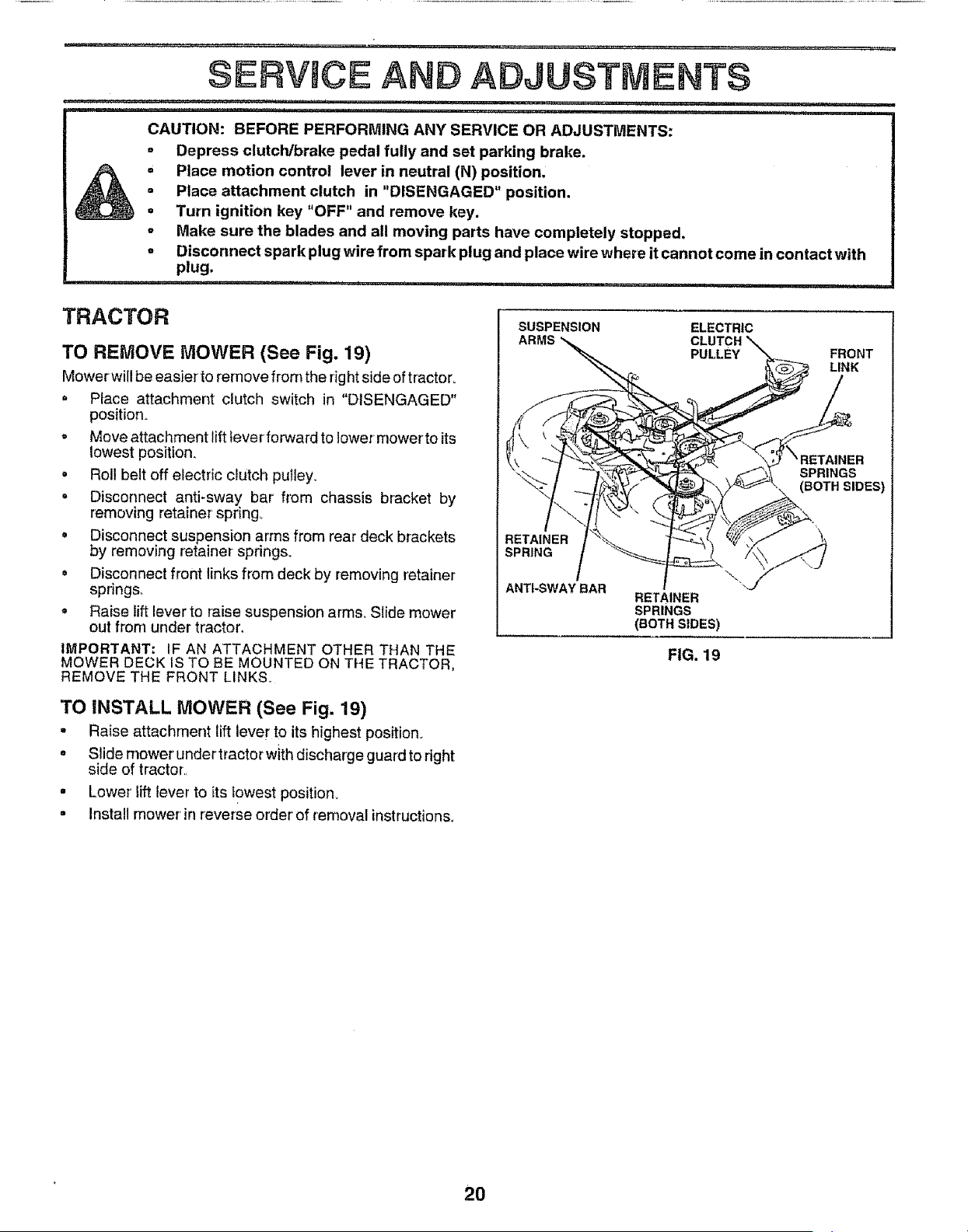
TO REMOVE MOWER (See Fig. 19)
Mower wi!!be easier to remove from the rig htside oftractor°
, Place attachment clutch switch in "DISENGAGED"
position.
- Move attachment lift fever forward to lower mower to its
lowest position.
• Roll belt off electric clutch pulley.
= Disconnect anti-sway bar' from chassis bracket by
removing retainer spring_
o Disconnect suspension arms from rear deck brackets
by removing retainer springs_
= Disconnect front links from deck by removing retainer
spnngs_
, Raise lift lever to raise suspension arms. Slide mower
out from under tractor,
IMPORTANT: IF AN ATTACHMENT OTHER THAN THE
MOWER DECK IS TO BE MOUNTED ON THE TRACTOR,
REMOVE THE FRONT LINKS..
TO INSTALL MOWER (See Fig. 19)
. Raise attachment lift lever to its highest position_
o Slide mower undertractorwith discharge guard to right
side of tractor.
° Lower lift lever to its lowest position.
= Install mower' in reverse order' of removal instructions.
SUSPENSION ELECTRIC
ARMS CLUTCH
PULLEY FRONT
LINK
SPRINGS
\ (BOTH SIDES)
RETAINER
SPRING
ANTI-SWAY BAR
RETAINER
SPRINGS
(BOTH SIDES)
FIG. 19
20
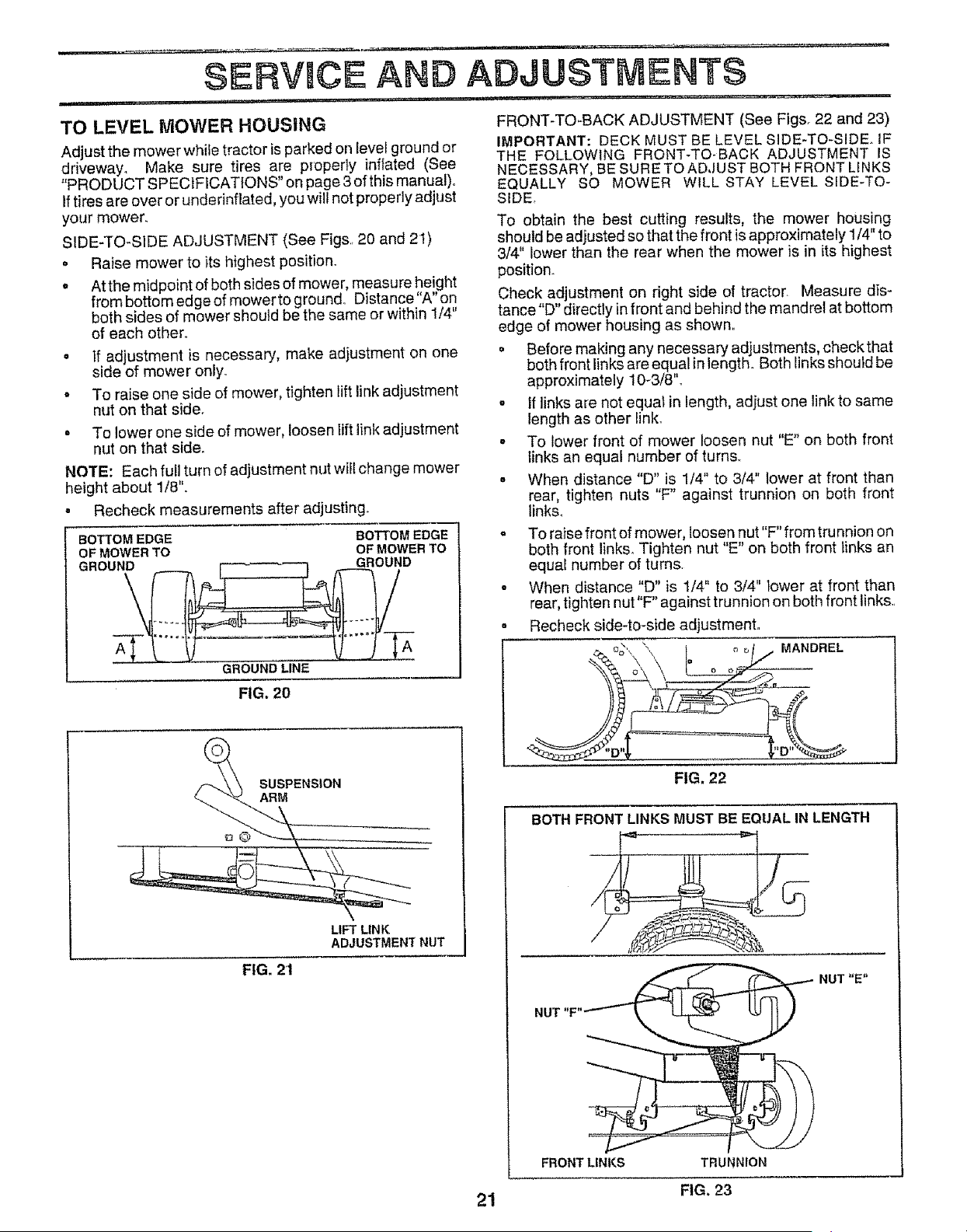
TO LEVEL MOWER HOUSING
Adjust the mower while tractor is parked on level ground or
driveway. Make sure tires are properly inflated (See
"PRODUCT SPECIFICATIONS" on page 3of this manual)°
If tires are over or underinflated, you will not properly adjust
your mower.
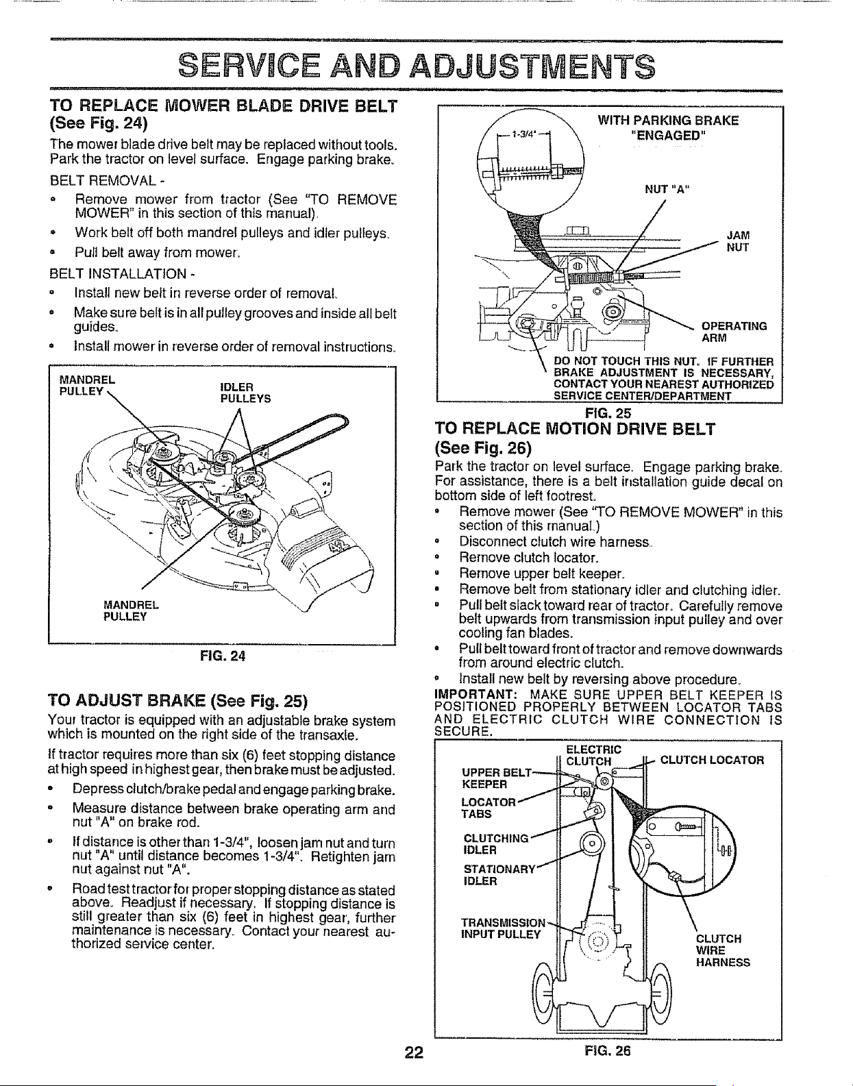
SIDE-TO-SIDE ADJUSTMENT (See Figs,, 20 and 21)
• Raise mower to its highest position.
o At the midpoint of both sides of mower, measure height
from bottom edge of mower to ground. Distance"A" on
both sides of mower should be the same or within 1/4"
of each other,,
o If adjustment is necessary, make adjustment on one
side of mower only.,
o To raise one side of mower, tighten lift link adjustment
nut on that side.
o To lower one side of mower, loosen lift link adjustment
nut on that side,,
NOTE: Each full turn of adjustment nut will change mower
height about 1/8".
° Recheck measurements after adjusting.
BOTTOMEDGE BOTTOMEDGE
OFMOWERTO OFMOWERTO
GROUND [-_,----_ GROUND
GROUND LINE
FIG. 20
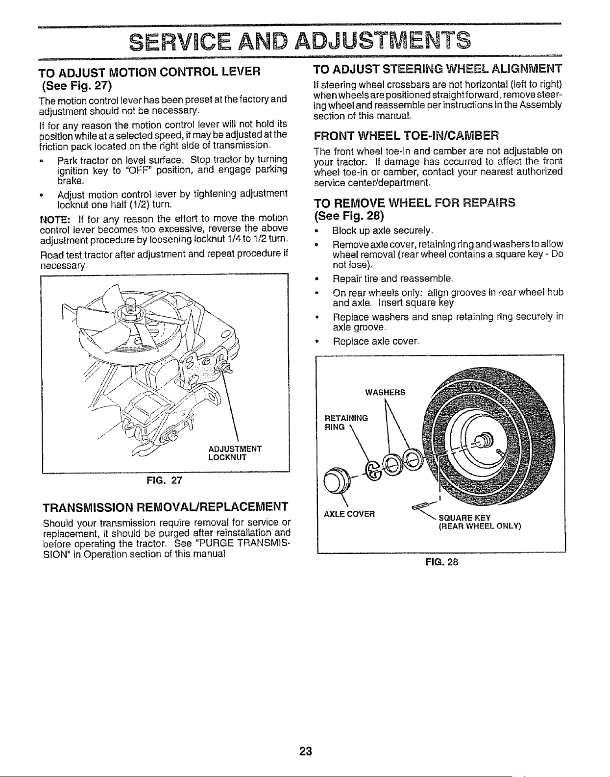
FRONT-TO-BACK ADJUSTMENT (See Figs. 22 and 23)
IMPORTANT: DECK MUST BE LEVEL SIDE-TO-SIDE. IF
THE FOLLOWING FRONT-TO-BACK ADJUSTMENT IS
NECESSARY, BE SURE TO ADJUST BOTH FRONT LINKS
EQUALLY SO MOWER WILL STAY LEVEL SIDE-TO-
SIDE_
TO obtain the best cutting results, the mower housing
should be adjusted so that the front is approximately 1/4" to
3/4" lower than the rear when the mower is in its highest
position.
Check adjustment on right side of tractor, Measure dis-
tance"D" directly in front and behind the mandrel at bottom
edge of mower housing as shown,,
o Before making any necessary adjustments, check that
both front links are equal in length. Both links should be
approximately 10-3/8"o
• If links are not equat in length, adjust one link to same
length as other linko
• To lower front of mower loosen nut "E" on both front
links an equal number of turns,,
- When distance "D" is 1/4" to 3/4" lower at front than
rear, tighten nuts "F" against trunnion on both front
links.
. To raise front of mower, loosen nut"F" from trunnion on
both front links,,Tighten nut "E" on both front links an
equal number of turns,
o When distance "D" is !/4" to 3/4" lower at front than
rear, tighten nut"F" against trunnion on both front links.,
. Recheck side-to-side adjustment,,
MANDREL
SUSPENSION
ARM
LIFT LINK
ADJUSTMENT NUT
FIG. 2'1
21
FIG. 22
BOTH FRONTLINKS MUST BE EQUAL IN LENGTH
NUT "E"
FRONT LINKS TRUr _ION
FIG, 23
= ,,,H ,, ,
SERVICE AN
TO REPLACE MOWER BLADE DRIVE BELT
(See Fig. 24)
The mower blade drive belt may be replaced without tools,
Park the tractor on level surface. Engage parking brake.
BELT REMOVAL-
= Remove mower from tractor (See "TO REMOVE
MOWER" in this section of this manual),
o Work belt off both mandrel pulleys and idler pulleys.
o Pull belt away from mower.
BELT INSTALLATION
= Instali new belt in reverse order of removal
,' Make sure belt is inall pulley grooves and inside all belt
guides°
= Install mower in reverse order of removal instructions,,
IDLER
PULLEYS
MANDREL
PULLEY
FIG. 24
MANDREL
TO ADJUST BRAKE (See Fig, 25)
Your tractor is equipped with an adjustable brake system
which is mounted on the right side of the transaxfe,
Iftractor requires more than six (6) feet stopping distance
at high speed inhighest gear, then brake must be adjusted.
o Depress clutch_rake pedal and engage parking brake.
o Measure distance between brake operating arm and
nut "A" on brake rod.
= If distance is other than !-3/4", loosen jam nut and turn
U 1 ti • ' t_ * •
n t A untd distance becomes t-3/4 o Ret ghten jam
nut against nut "A".
• Road test tractor for proper stopping distance as stated
above. Readjust if necessary, If stopping distance is
still greater than six (6) feet in highest gear', further
maintenance is necessary. Contact your nearest au-
thodzed service center_
ADJUSTMENTS
....... t_
WITH PARKING BRAKE
"ENGAGED"
JAM
NUT
OPERATING
ARM
DO NOT TOUCH THIS NUT° tF FURTHER
BRAKE ADJUSTMENT IS NECESSARY,
CONTACT YOUR NEAREST AUTHORIZED
SERVICE CENTER/DEPARTMENT
FIG, 25
TO REPLACE MOTION DRIVE BELT
(See Fig. 26)
Park the tractor on level surface. Engage parking brake.
For assistance, there is a belt installation guide decal on
bottom side of left footrest.
* Remove mower (See "TO REMOVE MOWER" inthis
section of this manual)
o Disconnect clutch wire harness,,
o Remove clutch tocator.
° Remove upper belt keeper,
° Remove belt from stationary idler and clutching idler.
= Pull belt slack toward rear of tractor,. Carefully remove
belt upwards from transmission input pulley and over
cooling fan blades.
= Puff belt toward front of tractor and remove downwards
from around electric clutch.
= install new belt by reversing above procedure.
IMPORTANT: MAKE SURE UPPER BELT KEEPER IS
POSITIONED PROPERLY BETWEEN LOCATOR TABS
AND ELECTRIC CLUTCH WIRE CONNECTION IS
SECURE.
ELECTRIC
CLUTCH ,,- CLUTCHLOCATOR
UPPERBELT"----- _
KEEPER -_"_J__JJ.
LOCATOR/ ",.'_?:_-', [_
TABS
"- _\ I o (]_=,41h\
CLUTCHING""- _ J _ l J
IDLER 3 li
STAT|ONARY"_'_ / I % ]1/
TRANSMISSION'-,. . .,J_.-' ,.1-,
,NPUTPULLEY " 'UTC.
, ,, .-.,,, _ WIRE
HARNESS
22 FiG. 26
i - -...i i i .u.ii
TO ADJUST MOTION CONTROL LEVER
(See Fig. 27)
The motion control lever has been preset at the factory and
adjustment should not be necessary.
If for any reason the motion control lever will not hold its
position while at a selected speed, itmay beadjusted at the
friction pack located on the right side of transmission°
o Park tractor on !evel ,surface, Stop tractor by turning
ignition key to OFF position, and engage parking
brake°
• Adjust motion control lever by tightening adjustment
Iocknut one half (1/2) turn.
NOTE: If for any reason the effort to move the motion
control lever becomes too excessive, reverse the above
adjustment procedure by loosening tocknut I/4 to 1/2 turn.
Road test tractor after adjustment and repeat procedure if
necessary.
i iii 1.1....i i.. ilUli1....i.ii. _ .. i..i....
SERVICE AND ADJUSTMENTS
......... i1....,.
TO ADJUST STEERING WHEEL AMGNMENT
If steering wheel crossbars are not horizontal (left to right)
when wheeis are positioned straightforward, remove steer-
ing wheel and reassemble per instructions in the Assembly
section of this manual,.
ADJUSTMENT
LOCKNUT
FIG. 27
TRANSMISSION REMOVAL/REPLACEMENT
Should your transmission require removal for service or
replacement, it shoutd be purged after reinstaliation and
before operating the tractor° See "PURGE TRANSMIS-
SION" in Operation section of this manual.
FRONT WHEEL TOE-INICAMBER
The front wheel toe-in and camber are not adjustable on
your tractor. If damage has occurred to affect the front
wheel toe-in or camber, contact your nearest authorized
service center/department.
TO REMOVE WHEEL FOR REPABRS
(See Fig, 28)
= Block up axle securely.
. Remove axle cover, retaining ring and washersto allow
wheel removal (rear wheel contains a square key - Do
not lose).
, Repair tire and reassemble,.
- On rear wheels only: align grooves in rear wheel hub
and axle. Insert square key.
o Replace washers and snap retaining ring securely in
axle groove°
• Replace axle cover,,
WASHERS
RETAINING
RING
Q
AXLE COVER
!
_ SQUARE KEY
(REAR WHEEL ONLY)
FIG. 28
23
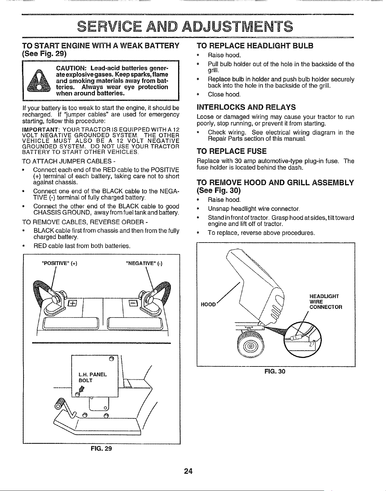
;ERV CE AND ADJUSTMENTS
TO START ENGINE WITH A WEAK BATTERY
(See Fig. 29)
........................................................... i
CAUTION: Lead-acid batteries gener-
_ ateexplosivegases. Keep sparks, flame
and smoking materials away from bat-
reties. Always wear eye protection
when around batteries.
,,, ,, ,111,, ii i, ,,111,=,_1 ,,,,, ,,,,,,,,, ,,,, ,,,,, , ,
If your battery is too weak to start the engine, it should be
recharged. If "jumper cables" are used for emergency
starting, follow this procedure:
IMPORTANT: YOUR TRACTOR tS EQUIPPED WITH A 12
VOLT NEGATIVE GROUNDED SYSTEM. THE OTHER
VEHICLE MUST ALSO BE A 12 VOLT NEGATIVE
GROUNDED SYSTEM. DO NOT USE YOUR TRACTOR
BATTERY TO START OTHER VEHICLES.
TO ATTACH JUMPER CABLES -
= Connect each end of the RED cable to the POSITIVE
(+) terminal of each battery, taking care not to short
against chassis_
= Connect one end of the BLACK cable to the NEGA-
TIVE (-) terminal of futly charged battery.
= Connect the other' end of the BLACK cable to good
CHASSIS GROUND, away from fuel tank and battery°
TO REMOVE CABLES, REVERSE ORDER -
° BLACK cable first from chassis and then from the fully
charged battery.
e
TO REPLACE HEADLIGHT BULB
o Raise hood.
o Pull bulb holder out of the hole in the backside of the
grill.
o Replace bulb in holder and push bulb holder'securefy
back into the hole in the backside of the grill
o Close hood.
INTERLOCKS AND RELAYS
Loose or damaged wiring may cause your tractor to run
poorly, stop running, or prevent it from starting_
° Check wiring. See electrical wiring diagram in the
Repair Parts section of this manual.
TO REPLACE FUSE
Replace with 30 amp automotive-type plug-in fuse_ The
fuse holder is located behind the dash.
TO REMOVE HOOD AND GRILL ASSEMBLY
(See Fig. 30)
• Raise hood..
• Unsnap headlight wire connector.
• Stand infront of tractor'. Grasp hood at sides, tilt toward
engine and lift off of tractor.
To replace, reverse above procedures..
RED cable last from both batteries.
(
"POSITIVE" (+) "NEGATIVE" (-}
LH, PANEL
BOLT
HOOD
HEADLIGHT
WIRE
CONNECTOR
FIG. 30
FIG. 29
24
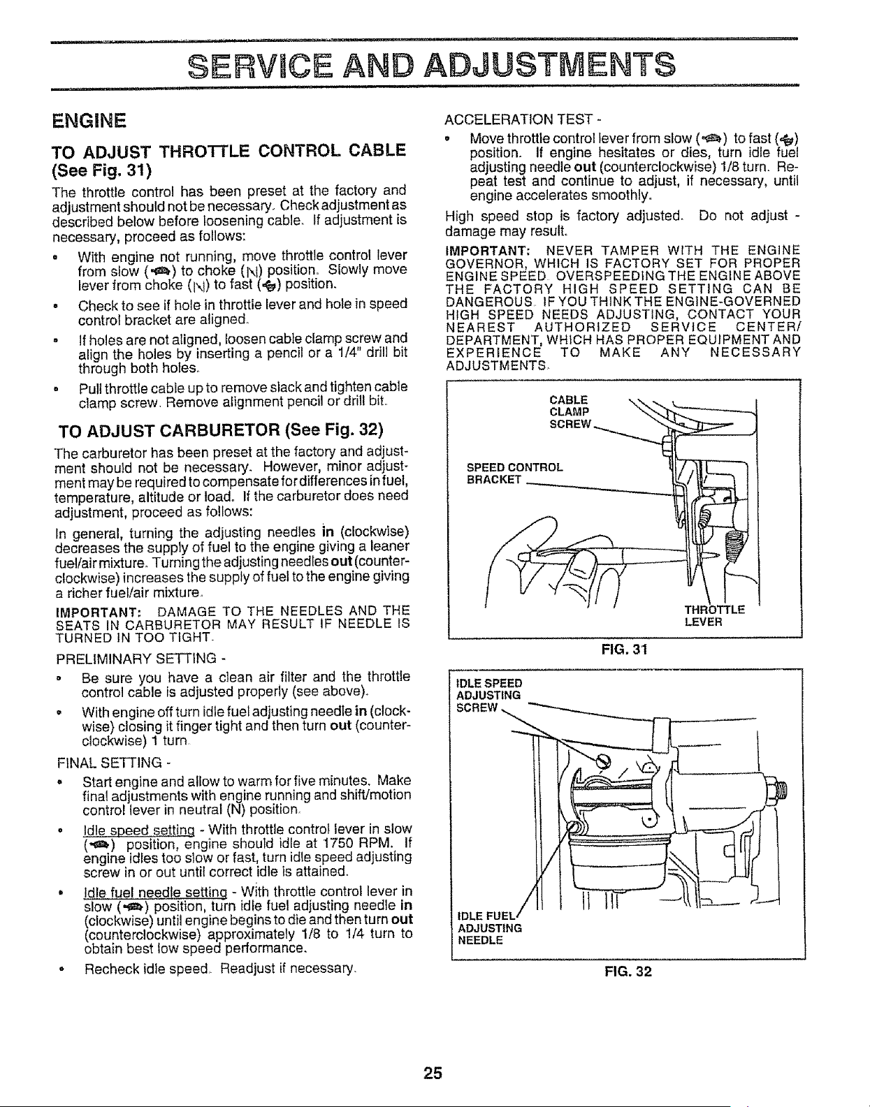
_ ---_,_r _- 'I I " I IIIII_
SERV(¢E AND ADJUSTMENTS
...... ii liH
ENGINE
TO ADJUST THRO'FrLE CONTROL CABLE
(See Fig. 31)
The throttle control has been preset at the factory and
adjustment should not be necessary. Check adjustment as
described below before loosening cable. If adjustment is
necessary, proceed as follows:
• With engine not running, move throttle control lever
from slow ('_) to choke iN) position° Slowly move
lever from choke (1\1)to fast (4_) position.
• Check to see if hole in throttle lever and hote in speed
control bracket are aligne&
- If holes are not aligned, loosen cable clamp screw and
align the holes by inserting a pencil or a 1/4" drill bit
through both hotes.
= Pull throttle cable up to remove slack and tighten cable
clamp screw. Remove alignment pencil or drill bit..
TO ADJUST CARBURETOR (See Fig. 32)
The carburetor has been preset at the factory and adjust _
ment should not be necessary. However, minor adjust-
ment may be required tocompensate fordifferences in fuel,
temperature, altitude or loado If the carburetor does need
adjustment, proceed as follows:
In general, turning the adjusting needles in (clockwise)
decreases the supply of fuel to the engine giving a leaner
fuel/air mixture. Turning the adjusting needles out (counter-
clockwise) increases the supply of fuel to the engine giving
a richer fuel/air mixture.
IMPORTANT; DAMAGE TO THE NEEDLES AND THE
SEATS IN CARBURETOR MAY RESULT IF NEEDLE IS
TURNED IN TOO TIGHT-
PRELIMINARY SETTING -
= Be sure you have a clean air filter and the throttle
control cable isadjusted properly (see above)_
= With engine off turn idlefuel adjusting needle in (clock-
wise) closing it finger tight and then turn out (counter-
clockwise) 1 turn
FINAL SETTING -
• Start engine and allow to warm for five minutes. Make
fina( adjustments with engine running and shift/motion
control lever in neutral iN) position.
• Idle speed setting - With throttle control lever in slow
(,_) position, engine should idle at 1750 RPM. If
engine idles too slow or fast, turn idle speed adjusting
screw in or out until correct idle is attained..
° Idle fuel needle setting - With throttle control lever in
slow (,_z_) position, turn idle fuel adjusting needle in
(clockwise) until engine begins to die and then turn out
(counterclockwise) approximately 1/8 to 1/4 turn to
obtain best low speed performance.
= Recheck idle speed, Readjust ifnecessary.
ACCELERATION TEST -
° Move throttle control lever from slow (=_) to fast (,€_)
position. If engine hesitates or dies, turn idle fuel
adjusting needle out (counterclockwise) 1/8 turn. Re-
peat test and continue to adjust, if necessary, until
engine accelerates smoothly.
High speed stop is factory adjuste& Do not adjust -
damage may result.
IMPORTANT: NEVER TAMPER WITH THE ENGINE
GOVERNOR, WHICH IS FACTORY SET FOR PROPER
ENGINE SPEED OVERSPEEDINGTHEENGINEABOVE
THE FACTORY HIGH SPEED SETTING CAN BE
DANGEROUS IF YOU THINK THE ENGINE-GOVERNED
HIGH SPEED NEEDS ADJUSTING, CONTACT YOUR
NEAREST AUTHORIZED SERVICE CENTER/
DEPARTMENT, WHICH HAS PROPER EQUIPMENT AND
EXPERIENCE TO MAKE ANY NECESSARY
ADJUSTMENTS
CABLE
CLAMP
SPEED CONTROL
BRACKET_
TH|
LEVER
FIG. 3'1
IDLE SPEED
ADJUSTING
SCREW.
ll llT- !1
IDLE FU
ADJUSTING
NEEDLE
FIG. 32
25
, STORAGE
Immediately prepare your tractor for storage at the end of
the season or' if the tractor will net be used for 30 days or
more.
B
CAUTION: Never store the tractor with i
A _ gasoline in the tank inside a building I
where fumes may reach an open flame i
or spark. Allow the engine to cool I
before storing in any enclosure. I
I
TRACTOR
Remove mower from tractor for winter storage. When
mower is to be stored for a period of time, clean it thor-
oughly, remove all dirt, grease, leaves, etc. Store in a
clean, dry area.,
. Clean entire tractor(See"CLEANfNG"in the Customer
Responsibilities section of this manual)_
o Inspect and replace belts, if necessary (See belt re-
placement instructions in the Service and Adjustments
section of this manual),
° Lubricate as shown in the Customer' Responsibilities
section of this manual.
o Be sure that all nuts, bolts and screws are securely
fastened. Inspect moving parts for damage, breakage
and wear.. Replace if necessary.
o Touch up all rusted or chipped paint surfaces; sand
lightly before painting.
BATTERY
• Fully charge the battery for storage..
= After a period of time in storage, battery may require
recharging.
o To help prevent corrosion and power leakage during
fong periods of storage, battery cables should be
disconnected and battery cleaned thoroughly (see'q'O
CLEAN BATTERY AND TERMINALS in the Cus-
tomer Responsibilities section of this manuai)o
• After cleaning, leave cables disconnected and place
cables where they cannot come in contact with battery
terminals,.
. Be sure battery drain tube is securely attached.
• If battery is removed from tractor for' storage, do not
store battery directly or] concrete or damp surfaces°
ENGINE
FUEL SYSTEM
IMPORTANT: IT IS IMPORTANT TO PREVENT GUM
DEPOSITS FROM FORMING IN ESSENTIAL FUEL
SYSTEM PARTS SUCH AS CARBURETOR, FUEL FILTER,
FUEL HOSE, OR TANK DURING STORAGE, ALSO,
EXPERIENCE INDICATES THAT ALCOHOL BLENDED
FUELS (CALLED GASOHOL OR USING ETHANOL OR
METHANOL) CAN ATTRACT MOISTURE WHICH LEADS
TO SEPARATION AND FORMATION OF ACIDS DURING
STORAGE. ACIDIC GAS CAN DAMAGE THE FUEL
SYSTEM OF AN ENGINE WHILE IN STORAGE,
, Drain the fuel tank,
• Start the engine and let it run until the fuel lines and
carburetor are empty°
• Never use engine or carburetor'cleaner'products in the
fuel tank or permanent damage may occur.
o Use fresh fuel next season_
NOTE: Fue! stabilizer is an acceptable alternative in
minimizing the formation of fuel gum deposits during stor-
age. Add stabilizer to gasoline in fuel tank or storage
container;. Always follow the mix ratio found on stabilizer
container'. Run engine at least 10 minutes after' adding
stabilizer to allow the stabilizer to reach the carburetor. Do
not drain the gas tank and carburetor if using fuel stabilizer.
ENGINE OIL
Drain oil (with engine warm) and replace with clean engine
oilo (See "ENGINE" in the Customer Responsibilities
section of this manual).
CYLINDERS
o Remove spark plug(s).,
= Pour one ounce of oil through spark plug hole(s) into
cylinder(s).
. Turn ignition key to"START" position fora few seconds
to distribute oil.
, Replace with new spark plug(s).
OTHER
° Do not store gasoline from one season to another°
• Replace your gasoline can if your can starts to rust.
Rust and/or dirt in your' gasoline will cause problems.
• If possible, store your tractor indoors and cover it to
give protection from dust and dirt.
,, Cover your tractor with a suitable protective covetthat
does not retain moisture. Do not use plastic. Plastic
cannot breathe which allows condensation to form and
will cause your tractor to rust.
IMPORTANT: NEVER COVERTRACTOR WHILE ENGINE
AND EXHAUST AREAS ARE STILL WARM.
26

. ....n. nl
lU . lUl..Ul,
I
PROBLEM
Will not start
Hard to start
, ,,i,nl,l,,
Engine will not turn over
i u i,,,,11,1
Engine clicks but wil! not
start
iii1,,i,ii
Loss of power
i , u ....... i, ,,,i,,
Excessive vibration
i i,nlu u....
TROUBLESHOOTING POmNTS
......=,,,i , ,, , i,, •
CAUSE
1. Outot fuel
2. Engine not "CHOKED" properly.
3 Engine flooded
4 Bad spark plug
5 Dirty air filter
6, Dirty fuel filter,
7 Water in fuel
8 Loose or damaged wiring
9 Carburetor out of adjustment,
I0 Engine valves out of adjustment,
1 Dirty air filter,
2, Bad spark plug
3, Weak or dead battery,,
4, Dirty fuel filter
5 Stale or dirty fuel
6 Loose or damaged wiring
7, Carburetor out of adiustment
8 Engine valves out of adjustment,
... ..................... ,,..,
1 Clutch/brake pedal not depressed
2 Attachment clutch is engaged
3 Weak or dead battery
4. Blown fuse.
5, Corroded battery terminals,
6 Loose or damaged wiring,
7 Faulty ignition switch.
8 Faulty solenoid or starter
9 Faulty operator presence switch(es),
1, Weak or dead battery_
2 Corroded battery terminals.
3 Loose or damaged wiring.
4 Faultysotenoid orstarter
1 Cutting too much grass/too fast
2 Throttle in "CHOKE" position
3, Build-up of grass, leaves and trash under mower,
4 Dirty air filter
5 Low oil levelldirty oil
6 Faulty spark plug,
7, Dirty fuel filter,
8 Stale or dirty fuel
9 Water in fuel
10 Spark plug wire loose
11 Dirty engine air screen/fins
t 2 Dirtytclogged muffler,
13 Loose or damaged wiring
14 Carburetor out of adjustment
15 Engine valves out of adjustment,
1 Worn, bent orloose blade
2 Bent blade mandrel,
3 Loose!damaged part(s)
CORRECTION
1 Filt fuel tank
2 See "TO START ENGINE" in Operation secfion,
3, Wait several minutes before attempting to start,
4 Replace spark plug
5 Cleanlreplace air filter
6, Replace fuer filter
7, Drain fuel tank and carburetor, refill tank with fresh
gasoline and replace fuel rifler.
8 Check all wiring,
9 Contact an authorized service center/department.
10. Contact an authorized service center/department
l Clean/replace air filter
2. Replace spark plug
3 Recharge or replace battery
4, Replace fuel _ter,
5, Drain fuel tank and refilI with fresh gasoitne
6 Check all wiring
7 Contact an authorized service center/department
8 Contact an authorized service center/department
1 Depress clutch/brake pedal
2 Disengage attachment clutch
3. Recharge or replace battery,
4 Replace fuse,
5. Clean battery terminals
6 Check all wiring.
7, Check]replace ignition switch
8. Check/replace solenoid or starter,
9. Contact an authorized service center/department.
1 Recharge or replace battery
2 Clean battery terminals
3 Check eel wiring
4. Check]replace solenoid or starter,,
f. Set in "Higher Cut" position#educe speed.
2 Adjust throttle control
3, Clean underside of mower housing
4 Cleanlreptace air filter,
5 Check ot{ level/change oil
6. Clean and regsp or change spark plug
7 Replace fuel filter
8 Drain lust tank and refil_with fresh gasoline
9, Drain fue_tank and carburetor, refill tank with fresh
gasoline and replace fuel filter
10 Connect and tighten spark plug wire,
11. Clean engine air screen!fins
12 Cteanlreptace muffler.
13 Check all wiring
14 Contact an authorized service center/department,
15, Contact an authorized service center/department,.
.................. .......... i .ul .lu
t Replace blade Tighten btade bolt
2 Replace blade mandrel
3 Tighten toose part(s), Replace damaged parts,
27
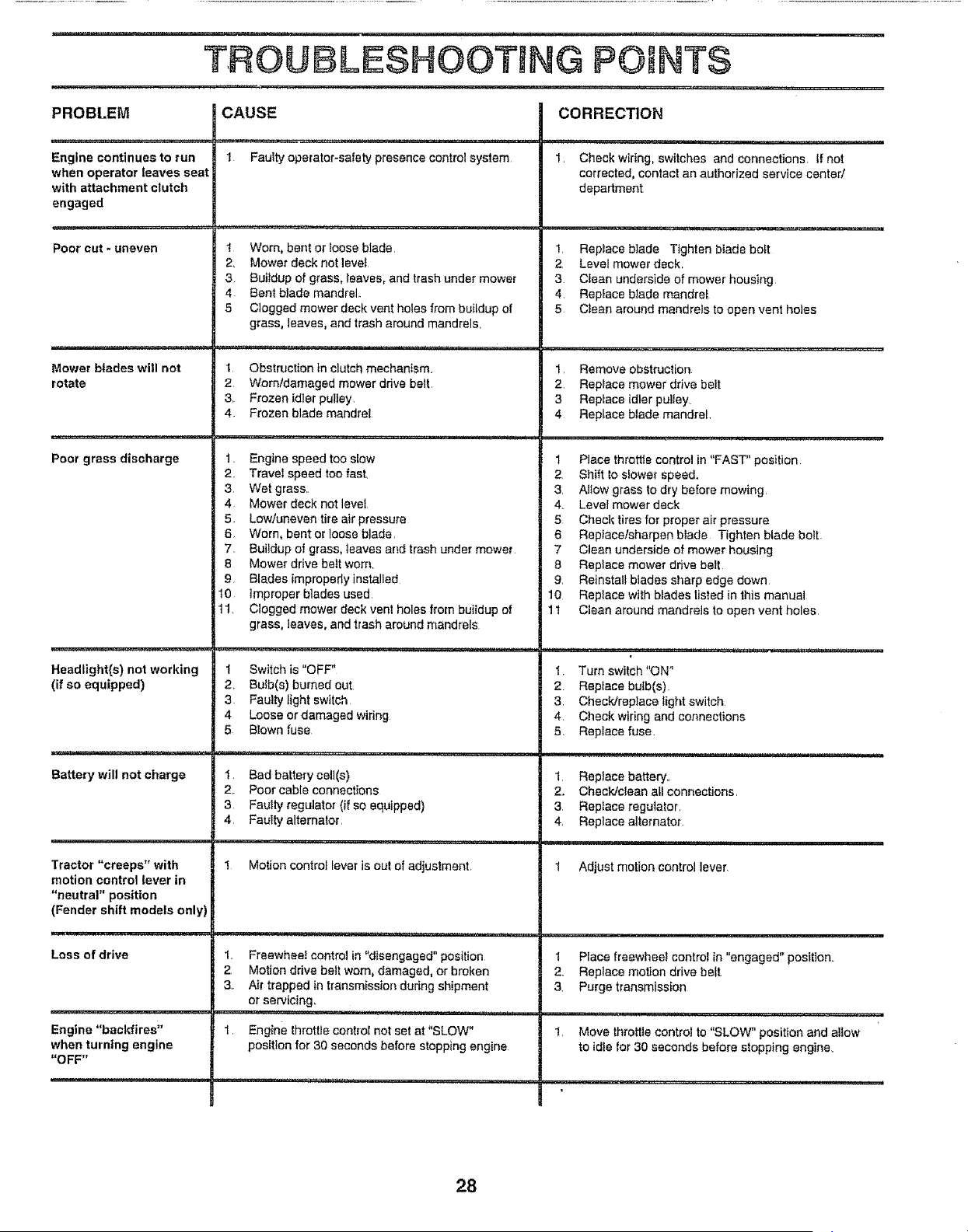
TROUBLESHOOTING POINTS
PROBLEM
Engine continues to run
when operator leaves seat
with attachment clutch
engaged
Poor cut - uneven
=,,=-.=i- i
Mower blades will not
rotate
Poor grass discharge
Headlight(s) not working
(if so equipped)
Battery will not charge
Tractor "creeps" with
motion control lever in
"neutral" position
(Fender shift models only)
Loss of drive
Engine "backfires"
when turning engine
"OFF"
CAUSE
1 Faulty operator-safety presence control system
,,==,-=,,, ,H,=.............. = ,=........
1 Worn, bent or loose blade
2, Mower deck not level
3 Buildup of grass, leaves, and trash under mower
4 Bent blade mandrel.
5 Clogged mower deck vent hales from buildup of
grass, leaves, and trash around mandrels,
1 Obstruction in clutch mechanism.
2 Worn/damaged mower ddve belt
3, Frozen idler pulley,
4 Frozen blade mandret
1, Engine speed too slow
2 Travel speed too fast,
3, Wet grass,.
4 Mower deck not level
5 Low/uneven tire air pressure
6 Worn, banter loose blade,
7 Buildup of grass, ]eaves and trash under mower
8 Mower ddve bait worn,
9 Blades improperly instalJed
10 improper bladesused
11_ Clogged mower deck vent holes from buildup of
grass, leaves, and trash around mandrels
1 Switch is "OFF"
2, Bulb(s) burned out
3 Faulty fight switch
4 Loose or damaged widng
5 Blown fuse
1. Bad battery cell(s)
2 Poor cable connections
3 Faulty regulator (if so equipped)
4. Faulty alternator,
1 Motion control lever is out of adjustment,
1. Freewheel control in "disengaged" position
2 Motion drive belt worn, damaged, or broken
3. Air trapped in transmission during shipment
or servicing.
,1111,1,,i, i1,,,11,,i,, i i i..... i i
1, Engine throttle control not set at "SLOW"
position for 30 seconds before stopping engine
CORRECTION
,!t,,, =,H,
1, Check wiring, switches and connections, If not
corrected, contact an authorized service center/
department
1, Reptace blade Tighten bJade bo_t
2 Level mower deck,
3 Clean underside of mower housing
4, Replace blade mandre_
5 Cieen around mandrels to open vent holes
1, Remove obstruction
2 Replace mower drive bait
3 Replace idler pulley_
4 Replace blade mandrel,
1 Place throttle control in "FAST" position
2 Shift to slower speed.
3 Altow grass to dry before mowing
4. Level mower deck
5 Check tires for proper air pressure
6 Reptacetsharpen blade Tighten blade bolt
7 Clean underside of mower housing
8 Replace mower drive belt
g, Reinstall blades sharp edge down
10 Reptace with blades listed in this manual
11 Clean around mandrels to open vent holes
.=,=,,= ,,,, i=, , i= = ,
I Turn switch "ON"
2 Replace bulb(s).
3 Check/replace light switch
4 Check wiring and connections
5 Replace fuse
I Repface battery,.
2., Check/clean all connections,
3 Replace regulator,
4, Replace alternator
1 Adjust motion control lever
1 Place freewheel control in "engaged" position.
2. Replace motion drive bait,
3. Purge transmission
1, Move throttle control to "SLOW" position and altow
to idle for 30 seconds before stopping engine,
28
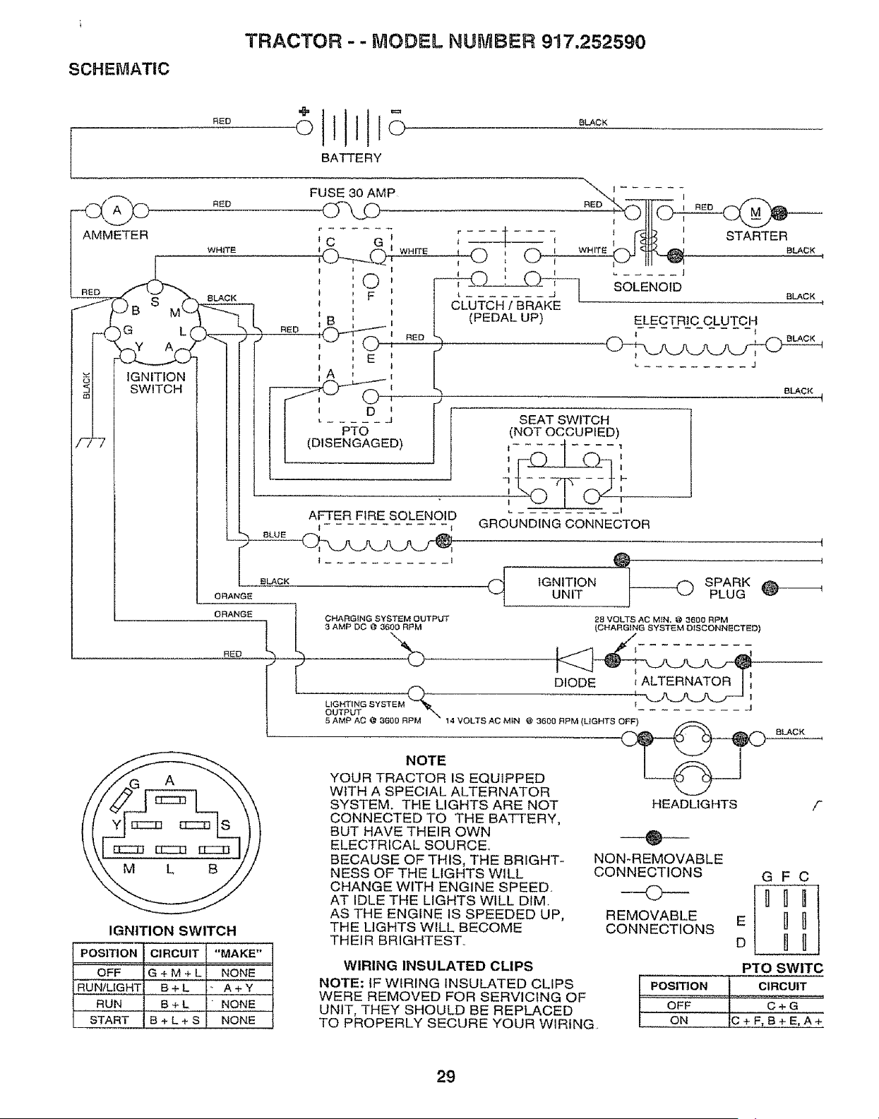
SCHEMATIC
TRACTOR -- MODEL NUMBER 917.252590
RED
BATTERY
BLACK
_M_ RED
TER WHITE
....eLACK
ORANGE
ORANGE
RED
CHARGING SYSTEM OUTPLrf
3 AMP DC @ 3600 RPM
%
(_ IGNITION SPARK
UNIT PLUG
28 VOLTS AC M{N. @ 3600 RPM
(CHARGING SYSTEM DISCONNECTED)
I
DIODE _ALTERNATOR
OUTPUT -.. "_ -- --
5 AMP AC @ 3600 RPM 14 VOLTS AC MIN @ 3600 RPM {LIGHTS OFF)
NOTE I I
YOUR TRACTOR IS EQUIPPED L---<O
WITH A SPECIAL ALTERNATOR
IGNITION SWITCH
POSITION ICIRCUIT "MAKE"
I
OFF G + M + L NONE
RUN/LIGH'[ B + L _ A + Y
RUN B + L " NONE
START B + L + S NONE
SYSTEM. THE LIGHTS ARE NOT
CONNECTED TO THE BATTERY,
BUT HAVE THEIR OWN
ELECTRICAL SOURCE,,
BECAUSE OF THIS, THE BRIGHT-
NESS OF THE LIGHTS WILL
CHANGE WITH ENGINE SPEED.
AT IDLE THE LIGHTS WILL DIM.
AS THE ENGINE IS SPEEDED UP,
THE LIGHTS WILL BECOME
THEIR BRIGHTEST,
WIRING INSULATED CLIPS
NOTE: IF WIRING INSULATED CLIPS
WERE REMOVED FOR SERVICING OF
UNIT, THEY SHOULD BE REPLACED
TO PROPERLY SECURE YOUR WIRING
HEADLIGHTS f
--0--
NON-REMOVABLE
CONNECTIONS
©
REMOVABLE
CONNECTIONS
GFC
E _ _
PTO SWITC
CIRCUIT
C+G
ON {C+F,B+E,A+
29

30


