
1
Portable Air Conditioning Unit
SRCOOL12K – Series Number: AG-0073 (120V, 60 Hz)
SRXCOOL12K – Series Number: AG-00A0 (230V, 50 Hz)
SRXCOOL12KA – Series Number: AG-0533 (230V, 50 Hz)
SRXCOOL12KB – Series Number: AG-00A0 (230V, 50 Hz)
Owner’s Manual
Introduction 2
Important Safety Instructions 2
Features 4
Installation 5
Operation 9
Cleaning and Maintenance 10
Troubleshooting 11
Storage and Service 12
Circuit Diagrams 12
Warranty and Product Registration 13
Regulatory Compliance 13
Español 14
Français 27
40
1111 W. 35th Street, Chicago, IL 60609 USA • tripplite.com/support
Copyright © 2020 Tripp Lite. All rights reserved.
WARRANTY REGISTRATION
Register your product today and be
automatically entered to win an ISOBAR
®
surge protector in our monthly drawing!
tripplite.com/warranty
SYST
RPS
STAT
DUPLX
SPEED
MODE
1
5
X
3
1
X
3
3
X
4
7
X
5
0
MASTR
STACK
SYST
RPS
STAT
DUPLX
SPEED
MODE
1
5
X
3
1
X
3
3
X
MASTR
STACK
SYST
RPS
STAT
DUPLX
SPEED
MODE
1
5
X
3
1
X
3
3
X
MASTR
STACK
MODE
1
5
X
3
1
X
3
3
X
STACK
4
7
X
5
0
4
7
X
5
0
4
7
X
5
0
4
7
X
5
0
5
0
2
Introduction
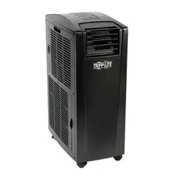
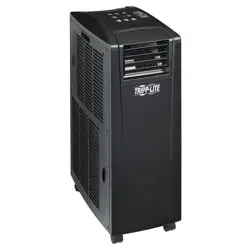
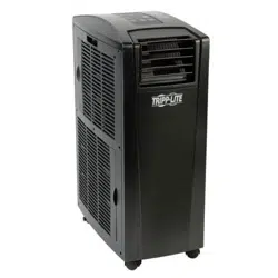
The self-contained Portable Air Conditioning Unit provides 12,000 BTU (up to 3.4 kW) of supplemental cooling capacity. Designed for IT
environments, it’s ideal for cooling overheated rack enclosures, IT equipment hot spots and network closets without access to facility air
conditioning. The Portable Air Conditioning Unit can focus cool air through its flexible cooling duct or cool a small room through its louvered vent.
It also filters and dehumidifies air to improve operating conditions and equipment reliability. Condensate is re-evaporated for drip-free operation,
so you won’t waste time emptying water collection tanks. The self-contained design does not require any plumbing or special circuits, so setup is
quick and easy. Eco-friendly R410A refrigerant meets environmental standards worldwide.
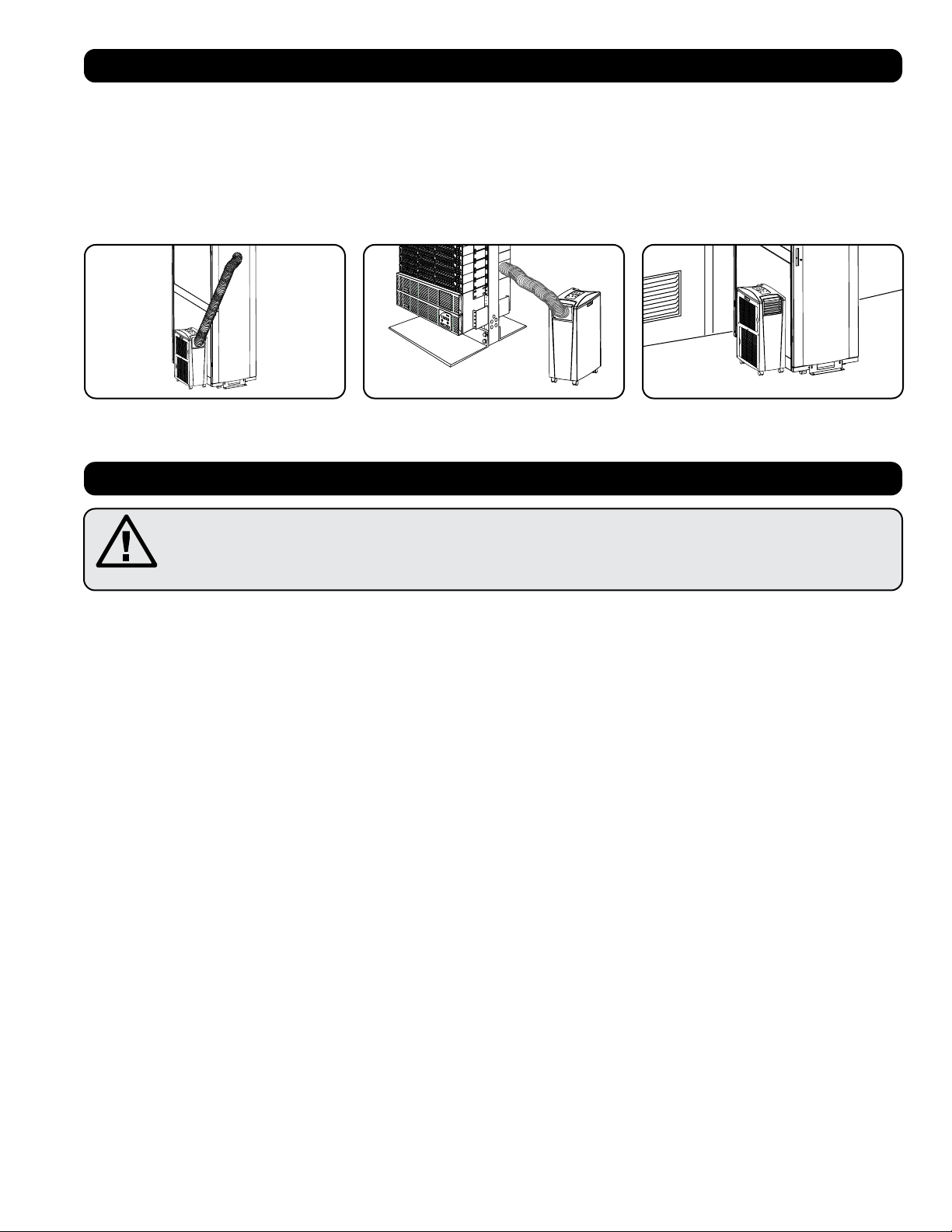
Recommended Applications:
Important Safety Instructions
SAVE THESE INSTRUCTIONS
This manual contains instructions and warnings that should be followed during the installation, operation
and storage of this product. Failure to heed these warnings may affect your warranty.
Warnings
• The individual user should determine prior to use whether this device is suitable, adequate or safe for the use intended. Since individual
applications are subject to great variation, the manufacturer makes no representation or warranty as to the suitability or fitness of this device
for any specific application.
• Install the unit indoors, away from extreme temperatures or humidity, direct sunlight, dust and conductive contaminants.
• Leave adequate space around the unit for ventilation, with rear and vented sides not less than 20 inches (51 cm) from walls or other
obstacles.
• Install the unit on a flat surface with a gradient no more than 10°.
• Connect the unit directly to a grounded AC power outlet. Failure to do so may cause an electric shock or fire.
• This unit is designed to supply supplemental cooling for localized hot spots.
• The power supply for the unit must be rated in accordance with the unit’s nameplate.
• Do not modify the plug nor use an adapter that would eliminate the ground connection.
• Do not use an extension cord to connect the unit to an AC outlet. Use only the power cord that came with the unit.
• Comply with all applicable wiring and safety regulations, such as National Electrical Code (NEC) in the United States.
• Do not plug additional equipment into the outlet where the unit is plugged in. Overloading the outlet may cause an electric shock or fire.
• Do not attempt to turn the unit on or off by connecting or disconnecting the AC plug. A serious electric shock may occur. Use the ON/OFF
button to turn the unit on or off.
• Turn the unit off and unplug it from the AC outlet before performing maintenance.
• Before connecting the unit to a dedicated drainage system, turn it off and unplug it. There is a risk of electric shock while the unit is plugged in.
• Do not use thinners, alcohol, detergents or abrasive brushes to clean the unit’s cabinet. These items may damage the cabinet.
• Do not pour water over the unit. This may cause an electric shock and damage the unit.
• Do not operate the unit without the air filter. This may cause dust accumulation that may damage the unit.
• Do not attempt to operate the unit in a room with inadequate air circulation. Provide makeup air in accordance with applicable building codes.
• Do not place objects on top of the unit.
• Do not operate your air conditioner in a wet room, such as a bathroom or laundry room.
• The applicable operating temperature range for this unit is 17°-35° (SRX Models only).
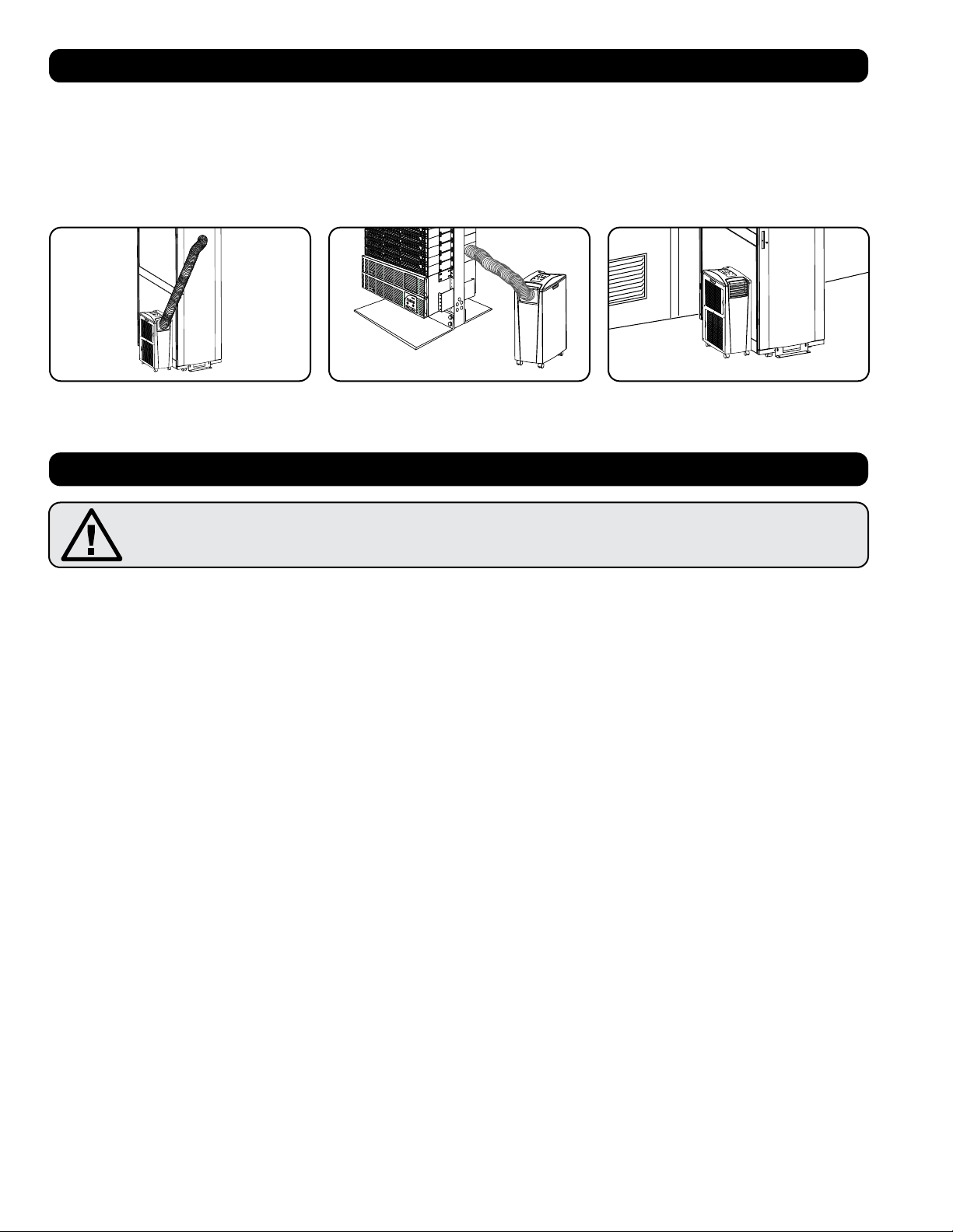
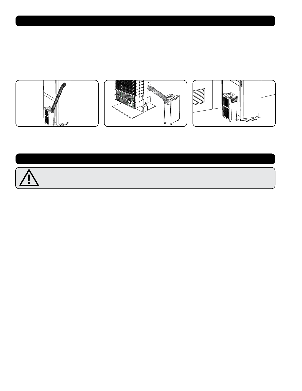
1. Cooling an overheated rack enclosure. 2. Cooling an equipment hot spot inside or
outside a rack enclosure.
3. Cooling a small room.

3
Important Safety Instructions
• This appliance is not intended for use by persons (including children) with reduced physical, sensory or mental capabilities, or lack of
experience and knowledge, unless they have been given supervision or instruction concerning use of the appliance by a person responsible for
their safety.
• Children should be supervised to ensure that they do not play with the appliance.
• Use of this equipment in life support applications where failure of this equipment can reasonably be expected to cause the failure of the life
support equipment or to significantly affect its safety or effectiveness is not recommended. Do not use this equipment in the presence of a
flammable anesthetic mixture with air, oxygen or nitrous oxide.
Impedance declaration
We declare the model AG-0533 (SRXCOOL12KA) be connected only to a supply with the relevant system impedance no more than 0.338 ohm.
Restrictions to connection may be imposed by the supply authority on the use of equipment if the actual relevant system impedance at the inter-
face point on the user’s premise exceeds 0.338 ohm.
A
ABF C D I
GH
E F
B
B
M
N
D
C
L
G
H K
I
F J
E E
4
Features
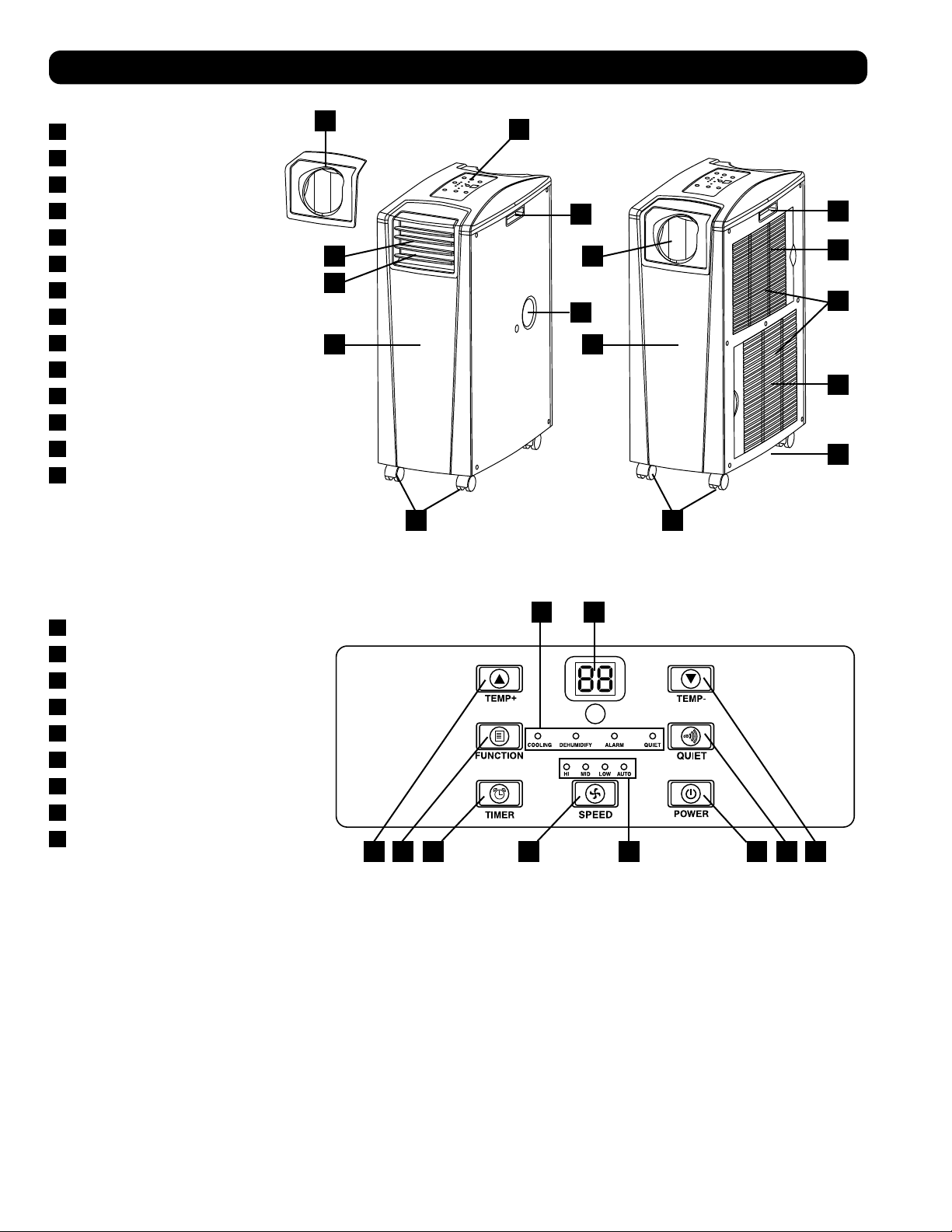
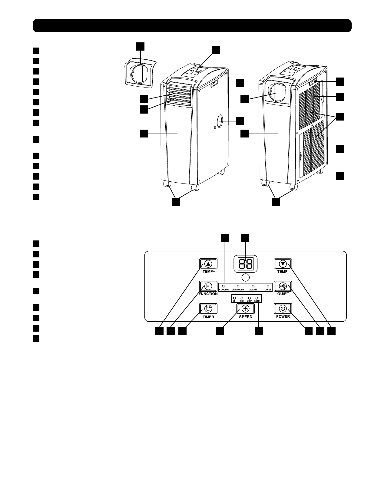
Front View
A
Control Panel
B
Recessed Handles
C
Air Filter Covers
D
Drainage Outlet
E
Casters
F
Front Panel
G
Cool Air Output
H
Louvered Vent Insert (Pre-Installed)
I
Cooling Duct Adapter (Optional)
J
Rear Panel
K
Warm Air Exhaust
L
Evaporator Drainage Outlet
M
Evaporator Filter
N
Condenser Filter
Control Panel
A
“POWER” Button
B
“FUNCTION” Button
C
“TIMER” Button
D
“FAN SPEED” Button
E
“QUIET” Button
F
Temperature Control Buttons
G
Numeric Display
H
Operating Mode LEDs
I
Fan Speed Mode LEDs
>
20 in (51 cm)
>
20 in (51 cm)
WALL
100 in.
2
(645 cm
2
)
Vent (For
Confined Spaces)
1
2-1
2-2
A
A
5
Installation
Warning: After removing the unit from the shipping container, check for damage or missing parts. (Refer to the parts list below.)
If you notice a problem, visit tripplite.com/support for service. Do not attempt to operate a damaged unit.
Accessory Parts List:
1
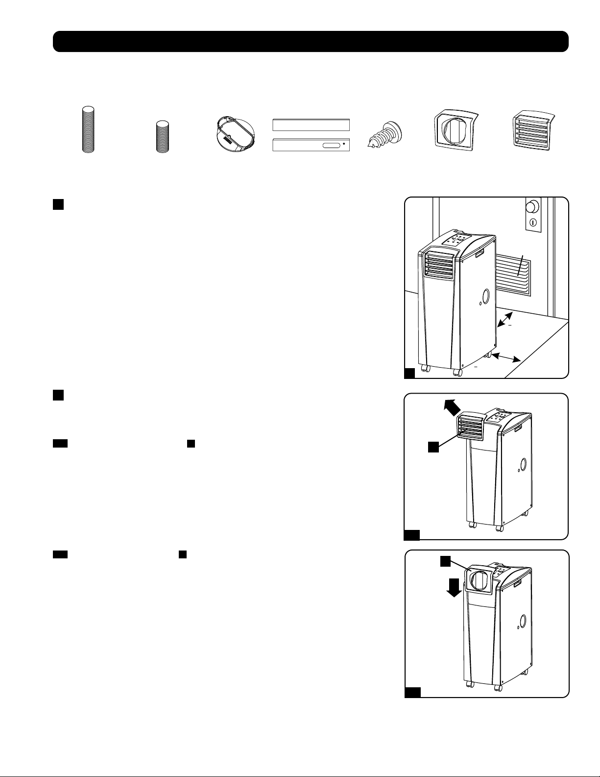
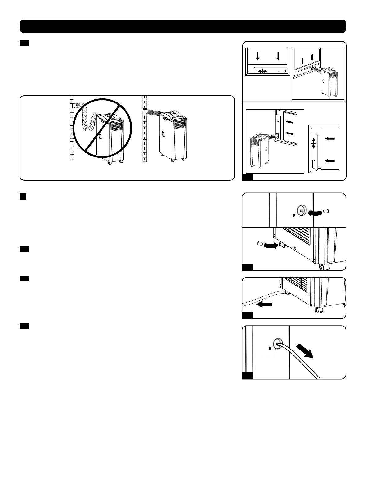
Unit Placement
Place the unit on a flat, level surface near a grounded AC outlet rated in accordance with the
unit nameplate (90-110% of specified voltage). Leave adequate space around the unit for
ventilation, with rear and vented sides not less than 20 inches (51 cm) from walls or other
obstacles. Place the unit in a location with convenient access to a drop ceiling or window to
provide the straightest, shortest path available for the flexible exhaust duct. If you plan to use
the flexible cooling duct to focus cool air on a specific rack enclosure or device, place the unit
near the targeted rack enclosure or device to provide the straightest, shortest path available for
the cooling duct.
Warning: Do not use an extension cord to connect the unit to an AC outlet. Use
only the power cord that came with the unit.
Note: If the unit will operate in a confined space (such as closet), you must supply makeup air
in order to maintain airflow efficiency. A 100 in.
2
(645 cm
2
) or larger vent installed near the
bottom of the door should supply adequate makeup air for a typical closet. Consult applicable
building codes for more information.
Exhaust hose not shown—see Section 3.
2
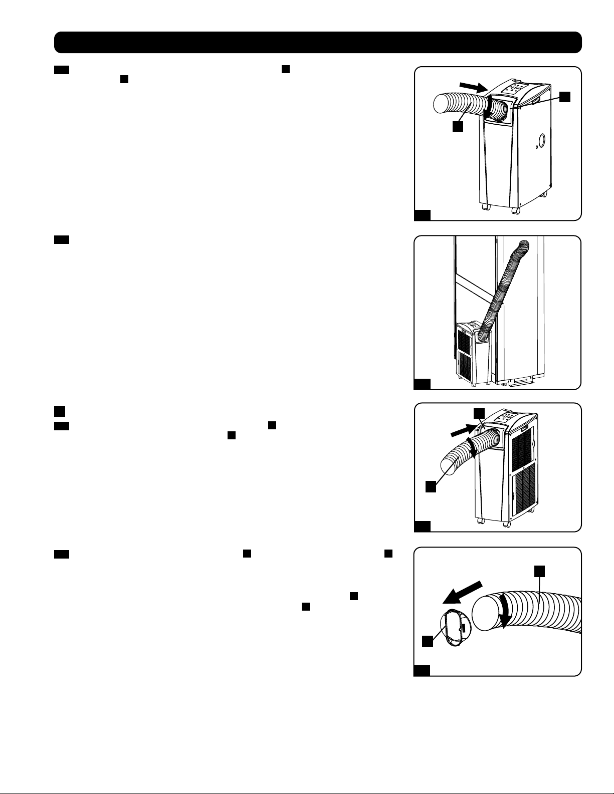
Cooling Duct Connection (Optional)
The pre-installed louvered vent insert is appropriate for room cooling applications. If you plan to
cool a room, skip step 2 and proceed to step 3. If you plan to use the flexible cooling duct to
focus cool air on a specific device or rack enclosure, follow the instructions below.
2-1
Remove the louvered vent insert
A
by pulling it outward and upward.
Exhaust Duct
(Longer Tube)
Cooling Duct
(Shorter Tube)
Exhaust Duct
Adapter
Adjustable
Exhaust Panel
(2 Sections)
Self-Tapping Screw 2 Duct Adapters
(1 Pre-Installed)
Louvered Vent
Insert
(Pre-Installed)
2-2
Align the cooling duct adapter
A
in the vent opening and push it downward until it snaps
into place.
1
2
1
2
1
2
2-3
2-4
3-1
3-2
A
A
B
B
A
B
6
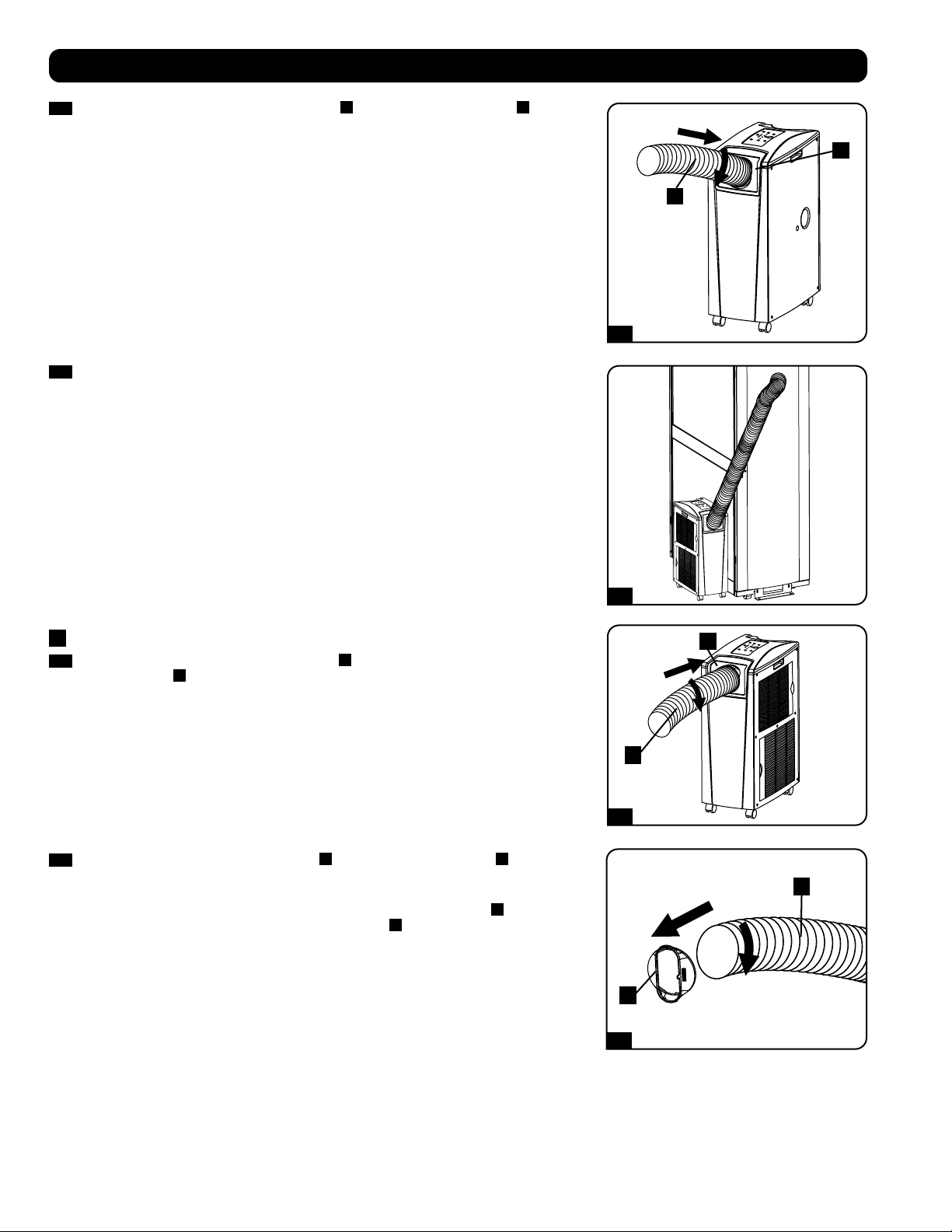
2-3
Connect the flexible cooling duct (shorter tube
A
) to the cooling duct adapter
B
. Align
the duct with the circular adapter opening, push the duct downward and turn the duct
clockwise until it screws into the adapter solidly.
Installation
2-4
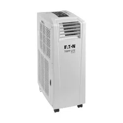
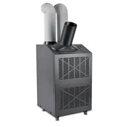
Place the other end of the cooling duct near the air intake of the target device or rack
enclosure, using the straightest, shortest path available. If you plan to cool a rack
enclosure, place the end of the cooling duct over a perforated area near the top of the
enclosure’s front door (or near the top of the bank of equipment that requires cooling).
Cool air will sink and spread across the air intakes at the front of the rack enclosure.
3
Exhaust Duct Connection
3-1
Connect the flexible exhaust duct (longer tube
A
) to the warm air exhaust vent on the rear
panel of the unit
B
. Align the duct with the circular vent opening, push the duct inward
and turn the duct clockwise until it screws into the exhaust vent solidly.
3-2
Connect the other end of the exhaust duct
A
to the exhaust duct adapter
B
. Align the
duct with the circular adapter opening, push the duct inward and turn the duct clockwise
until it screws into the adapter solidly.
If you plan to connect the exhaust duct to a drop ceiling, proceed to step
4
. If you plan to
connect the exhaust duct to a window, proceed to step
5
.
Self-Tapping Screw
Self-Tapping Screw
4-1
5-1
4-2
5-2
4-3
4-4
Ceiling Panel
(From Below)
Ceiling Panel
(From Above)
Exhaust Panel
7
Installation
4
Drop Ceiling Exhaust Connection
Warning: Some ceilings may require modified installation procedures. The user
must determine the fitness of hardware and procedures before installing. The
procedures described in this manual may not be appropriate for all applications.
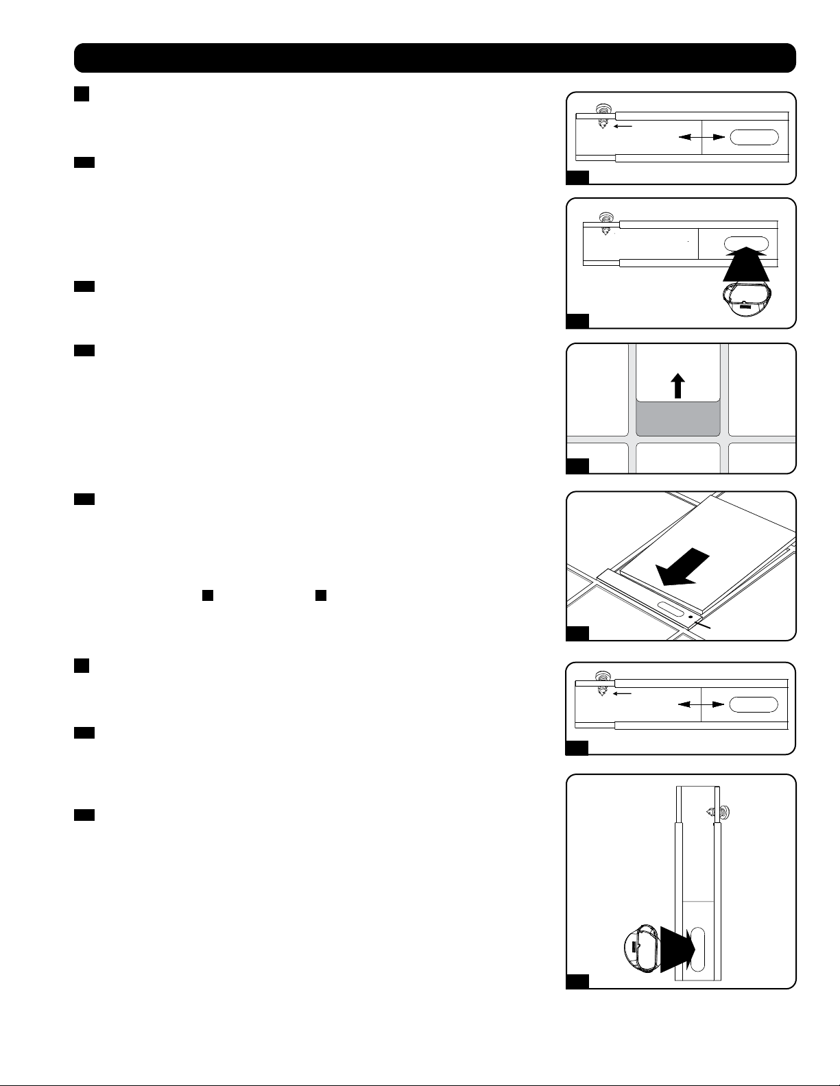
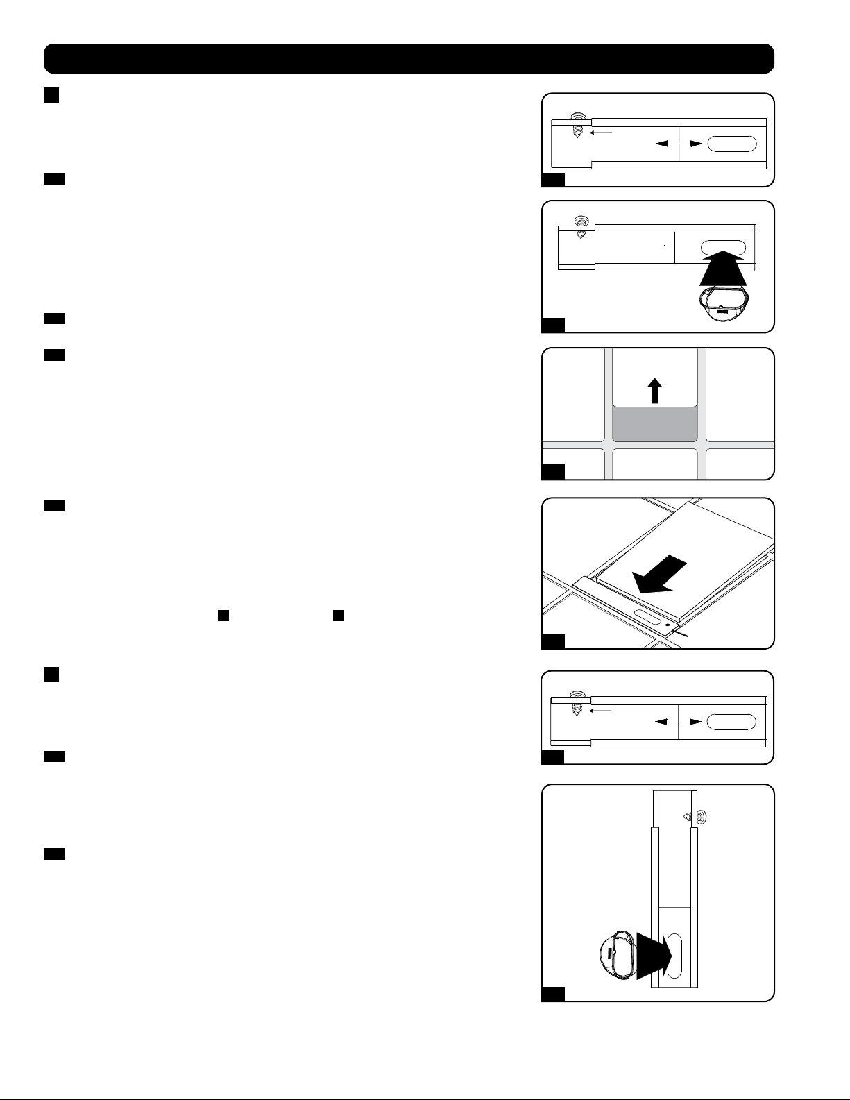
4-1
Choose a removable drop ceiling panel near the unit to provide the straightest, shortest
path available for the flexible exhaust duct. Measure the width of the ceiling panel,
including the portion that rests on the ceiling grid. Combine the two sections of the
adjustable exhaust panel, then adjust the exhaust panel to match the width of the ceiling
panel. After the exhaust panel is set to the correct width, use the included self-tapping
screw to lock it in place.
Note: The exhaust panel can adjust from 20.5 to 49.2 inches (52.1 to 104.1 cm).
Certain installations may require trimming the exhaust panel for a proper fit.
4-2
Insert the exhaust duct adapter into the oblong hole in the adjustable exhaust panel. The
adapter will snap into place.
4-3
Slide the ceiling panel out of the way and place the exhaust panel inside the ceiling space.
Allow the exhaust panel to rest on top of the ceiling grid.
Note: There must be at least 10 inches (25.4 cm) of open space above the exhaust panel
to allow adequate airflow.
4-4
Slide the ceiling panel back into place so that it adjoins the exhaust panel and closes any
gaps in the ceiling. A tight seal will permit maximum cooling efficiency. If the installation is
permanent, trim the ceiling panel so it doesn’t overlap the ceiling grid.
Note: The flexible exhaust duct can extend to a maximum length of 118 inches (300 cm).
Provide the straightest, shortest path available. Excessive bending or stretching of the duct
will reduce cooling efficiency.
After completing step
4
, proceed to step
6
.
5
Window Exhaust Connection
Warning: Some windows may require modified installation procedures. The user
must determine the fitness of hardware and procedures before installing. The
procedures described in this manual may not be appropriate for all applications.
5-1
Measure the window opening. Combine the two sections of the adjustable exhaust panel,
then adjust the exhaust panel to match the width of the window opening. After the exhaust
panel is set to the correct width, use the included self-tapping screw to lock it in place.
Note: The exhaust panel can adjust from 20.5 to 49.2 inches (52.1 to 104.1 cm). It is
compatible with vertical and horizontal mounting.
5-2
Insert the exhaust duct adapter into the oblong hole in the adjustable exhaust panel. The
adapter will snap into place.
Horizontal Window
Opening
Vertical
Window
Opening
INCORRECT CORRECT
5-3
6-1
6-2
6-3
TO EXTERNAL
DRAIN
TO EXTERNAL
DRAIN
8
Installation
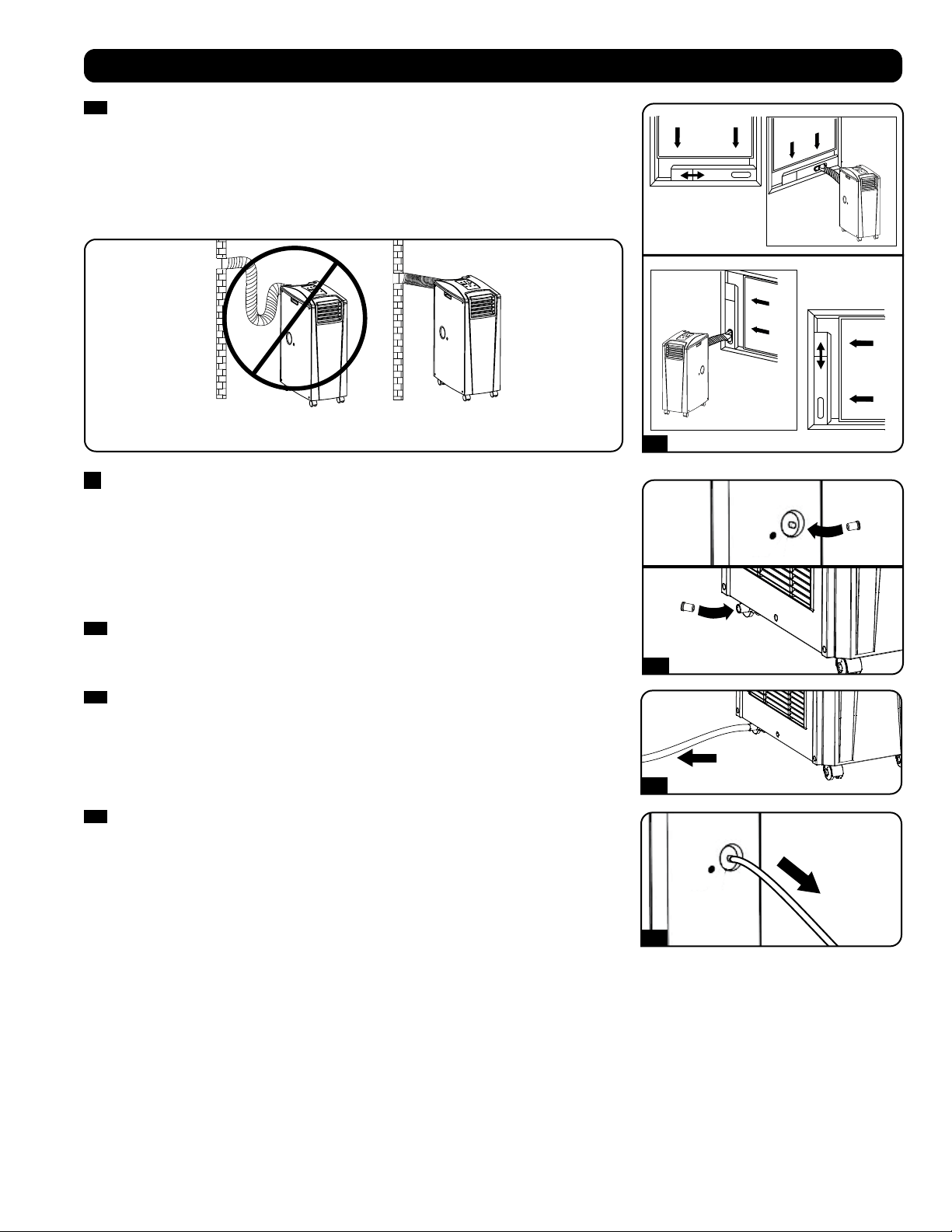
5-3
Insert the exhaust panel into the window opening, then close the window against the
exhaust panel. A tight seal will permit maximum cooling efficiency. Note: There must be
at least 10 inches (25.4 cm) of open space behind the exhaust panel to allow adequate
airflow.
Note: The flexible exhaust duct can extend to a maximum length of 118 inches (300 cm).
Provide the straightest, shortest path available. Excessive bending or stretching of the duct
will reduce cooling efficiency.
6
Drainage Plug Insertion
Warning: The unit’s built-in re-evaporator will not function until you insert the
drainage plug into the drainage outlet.
When the unit cools or dehumidifies, condensation forms. The unit has a built-in re-evaporator
that allows it to expel condensation through the warm air exhaust stream. This feature allows
the unit to operate indefinitely without requiring you to empty a water collection tank. The unit
ships with both the upper and lower drainage plugs installed.
6-1
Cooling Mode with Re-Evaporation
Both plugs must remain installed to enable re-evaporation of condensation.
6-2
Cooling Mode without Re-Evaporation
To use Cooling mode without re-evaporating condensation, remove the bottom drain plug
and route user-supplied drain line to external drainage. The top drain plug must remain
installed.
6-3
Dehumidify Mode
When using the unit in Dehumidify mode, remove the top drain plug and route user-
supplied drain line to external drainage. The bottom drain must remain installed. This will
maximize the amount of water removed from the air.
Note: If the drainage system becomes clogged, a small internal reservoir will collect
condensation. If the drainage system is not cleared before the internal reservoir fills, the
unit will shut down automatically.
Warning: Before connecting the unit to a dedicated drainage system, turn it
off and unplug it. There is a risk of electric shock while the unit is plugged in.
Note: If your building’s cooling system has night or weekend thermostat setbacks, has
periodic shutdowns, or has limited cooling capacity, you may need to consider alternatives
to the standard installation. This product is meant to be used as a supplemental cooling
device, and cannot make up for significant fluctuations in building temperature or
humidity.
Low Temperature Operation
The air conditioner is a high-performance cooler, capable of producing very cold air output. When using the unit in environments that are
already cold (68° F / 20° C) or less), Tripp Lite recommends using the Dehumidify mode only. This will allow the unit to continue to provide the
supplemental cooling while preventing any evaporator icing issues caused by the low room temperature.
9
Operation
Warning: Install the unit according to the instructions in the “Installation” section before attempting to operate it.
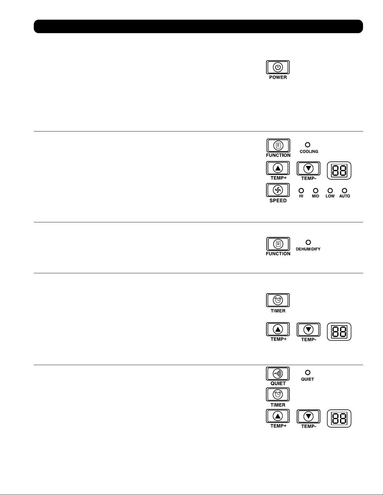
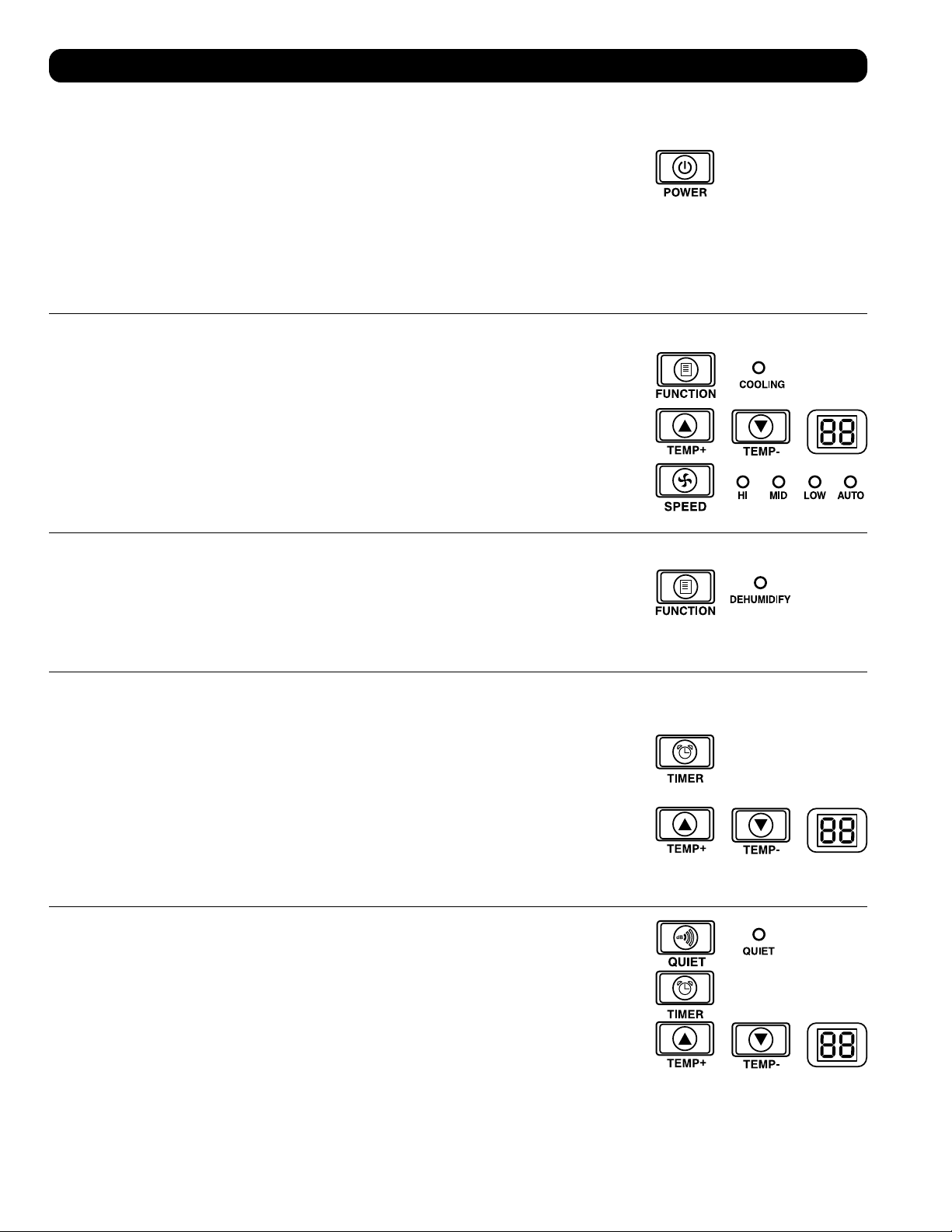
Power
Turn the unit on or off by pressing the “POWER” button.
The unit has a three-minute compressor delay in order to prevent potential circuit overloads at
start up.
Automatic Restart Feature
The unit will turn on and resume operation automatically when power is restored after a power
outage. The unit will use the same settings that it used immediately before the power outage
occurred. Note: If the power outage is brief, the unit will run the fan alone for three minutes
before resuming normal operation. The delay allows the compressor to depressurize so the unit
will function properly when it enters Cool mode.
Cool Mode
Pressing the “FUNCTION” button cycles between Cool mode and Dehumidify mode. The
“COOLING” LED illuminates when Cool mode is active.
Press the TEMP+ and TEMP- buttons to set the temperature in Cool mode. The selected
temperature is shown on the numeric display. Once set, the desired temperature will blink five
times after which the display will show the current room temperature.
Press the “FAN SPEED” button to cycle between high, medium and low fan speeds. An LED
illuminates to indicate the selected fan speed. When speed is set on AUTO, the unit will
automatically select a fan speed based on the set and ambient temperatures. If ambient
temperature is lower than the set temperature, the fan will run and the “COOLING” LED will
blink to indicate that the compressor is off. When cooling resumes, the “COOLING” LED will
remain illuminated.
Dehumidify Mode
Pressing the “FUNCTION” button cycles between Cool mode and Dehumidify mode.
The “DEHUMIDIFY” LED illuminates when Dehumidify mode is active. In Dehumidify mode, the
fan runs at a fixed speed and temperature controls are irrelevant. For optimal performance in
Dehumidify mode, close windows and doors, remove the top drain plug and route user-supplied
drain line to external drainage.
Timer
The “TIMER” button allows you to schedule the unit to turn on or off automatically.
Timer On (Note: The unit must be off to activate the Timer On function. Confirm that mode,
temperature and fan speed settings are correct before activating the Timer On function.)
Activate the timer by pressing the “TIMER” button. Press the TEMP+ and TEMP- buttons to
set the delay (in hours) before the unit will turn on. The number of hours is shown on the
numeric display. The number will flash on the screen five times before returning to the current
temperature.
Timer Off (Note: The unit must be on to activate the Timer Off function.) Activate the timer by
pressing the “TIMER” button. Press the TEMP+ and TEMP- buttons to set the delay (in hours)
before the unit will turn off. The number of hours is shown on the numeric display. The number
will flash on the screen five times before returning to the current temperature.
Quiet Control Mode
The unit includes a Quiet Control mode which regulates the cooling via the timer and
microprocessor to achieve quieter operation levels when noise is an issue.
To activate, press the “QUIET” button. The Quiet LED will turn on. Set the desired temperature
and then set the timer to the duration of the Quiet Control mode cycle. During the course of the
cycle, the microprocessor memory will adjust the preset temperature by 0.9°F (0.5°C) every 30
minutes until it reaches the desired temperature. Once the temperature is reached, the unit will
maintain the temperature for the duration of the set time.

A
A
10
Operation
Cleaning and Maintenance
Clean the air conditioner and clean or replace the filters regularly to maximize performance and efficiency, prolong the unit’s life, and qualify for
warranty if there is a performance issue.
Note: Always unplug the air conditioner from the power outlet before cleaning.
Cleaning the Air Filters
It is important to keep the air filters clean and free of dust. When the filters are dirty or clogged with dust, it decreases cooling efficiency and can
threaten air quality. Tripp Lite recommends cleaning the filters at least once every two weeks. If the unit is used in a dusty environment, the filters
may need to be cleaned or replaced weekly.
Before cleaning the filters, turn the unit off and unplug it! There is a risk of electric shock while the unit is plugged in.
Never run the cooling unit without the filter.
1. Turn the unit off and unplug it.
2. Remove the filters
A
by sliding them out of the cabinet.
3. Use a vacuum cleaner or tap the filter lightly to remove loose dust and dirt.
4. Wash the filters in warm water with a neutral detergent. Do not put the filters into a
dishwasher or use harsh detergents or chemicals. Allow the filters to air dry completely after
washing.
Note: Do not use water hotter than 104° F (40° C) to clean the filters.
5. Replace the filters by sliding them back into their original position.
6. Plug the unit in and resume normal operation.
Cleaning the Cabinet
Before cleaning the cabinet, turn the unit off and unplug it! There is a risk of
electric shock while the unit is plugged in.
1. Turn the unit off and unplug it.
2. Use a dry, non-abrasive cloth to wipe the cabinet. If necessary, use lukewarm water to
dampen the cloth. Never use abrasive chemicals, volatile substances, gasoline, benzene,
thinners, detergents, chemically treated cloths, or other harsh chemicals or cleaning solvents
that may damage the cabinet exterior. Do not pour water directly over the unit or into the
working parts. This causes a risk of electrical shock and deterioration of electrical components and wiring insulation.
3. Use a soft bristle brush to clean between the vents.
4. Carefully use a vacuum cleaner to clean the condenser coils.
Changing Degree Units
The unit can display temperature in both Celsius and Fahrenheit. The default setting for the
SRCOOL12K is Fahrenheit and the SRXCOOL12K, SRXCOOL12KA and SRXCOOL12KB are
Celsius.
To toggle between temperature modes, put the unit in standby mode. The air conditioner
is in standby mode when it is plugged into live AC power, but powered off. Then, hold the
“FUNCTION” key for 10 seconds. To verify the degree units have changed, power on the unit.
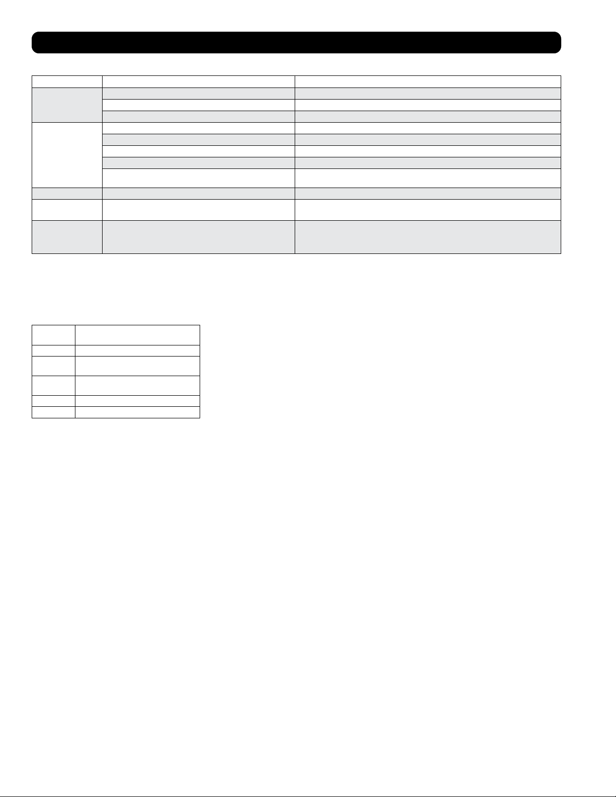
Alarm
When the water tank is full, the unit will display the message “E4” on its screen. To resume
normal function, turn the unit off, remove the drainage plug and drain the excess water from
the unit. Replace the plug and turn the unit on to begin cooling.
11
Troubleshooting
Additional Display Codes
Error Codes
The Tripp Lite SRCOOL12K/SRXCOOL12K/SRXCOOL12KA/SRXCOOL12KB has the ability to continually monitor itself. Should an error occur, the
display will show one of 5 error codes below:
Error Code Description
E0 Internal Communication Error
E1 Indoor Temperature Sensor Error
E2 Internal Temperature Sensor Error
E3 Refrigerant Error
E4 Water Full
dF Code
“dF” will display when the SRCOOL12K/SRXCOOL12K/SRXCOOL12KA/SRXCOOL12KB detects a condition in which the coil is operating below
33.8° F (1° C) for more than 15 minutes.
During a dF code event, the unit’s fans will run without the compressor to prevent the evaporator from freezing up. Once the coil temperature is
above 33.8° F (1° C), the compressor will resume normal operation.
If this condition persists, the unit is operating in an environment that is too cold. Tripp Lite recommends that the unit operate in Dehumidify mode
only if operating temperatures are below 68° F (20° C). See Low Temperature Operation in section 6-3 for more information.
Code E4 can be cleared by emptying the water tank. Consult the Alarm entry in the Operation
section for details.
For Codes E0, E1, E2, and E3 follow these steps:
1. Power cycle the unit by unplugging it from the source for 5 minutes.
2. Plug the unit back in.
3. Restart the unit.
If the code remains clear, continue to operate the unit as normal. If the code returns, please
contact Tripp Lite for further instructions.
Review the possible solutions below. If the problem persists, please visit tripplite.com/support for service.
Problem Possible Cause Possible Solution
The unit does not function. The unit is turned off. Turn the unit on. (See “Operation” section.)
The unit is not plugged in. Plug the unit into a suitable outlet.
Main power is off. Check fuses or circuit breaker.
Cooling performance is unsatisfactory. The air exhaust or intake is blocked. Confirm that all ducts and intakes are clear of obstructions.
The temperature setting is too high. Adjust the temperature setting.
The fan speed setting is too low. Adjust the fan setting.
The air filters are dirty. Clean the air filters.
The wattage of the rack enclosure, the size of
the room or the ambient temperature exceeds
the cooling capacity of a single unit.
Install additional units or contact Tripp Lite for additional cooling solutions suitable
for your application.
The unit leaks water. The drainage plug is not installed. Insert the drainage plug in the drainage outlet. (See “Installation” section.)
The unit generates excessive noise or
vibration.
The unit is on an uneven or unstable surface. Move the unit to a level, stable surface.
The unit has ice or frost buildup. The unit is operating in an environment with
excess humidity.
OPTION 1: Turn off the unit, and let the unit defrost. Once defrosted, ensure the
unit is operating with the fan speed set on HIGH.
OPTION 2: Turn off the unit, and let the unit defrost. Once defrosted, operate the
unit in DEHUMIDIFY MODE, or increase the desired temperature setpoint.
12
Storage and Service
Circuit Diagrams
Storage
Before storing the unit, confirm that the ducts and vents are secured or removed and cared for properly. Also confirm that the unit is drained of
condensation.
Service
Your Tripp Lite product is covered by the warranty described in this manual. A variety of Extended Warranty and On-Site Service Programs are also
available from Tripp Lite. For more information on service, visit tripplite.com/support. Before returning your product for service, follow these steps:
1. Review the installation and operation procedures in this manual to insure that the service problem does not originate from a misreading of the
instructions.
2. If the problem continues, do not contact or return the product to the dealer. Instead, visit tripplite.com/support.
3. If the problem requires service, visit tripplite.com/support and click the Product Returns link. From here you can request a Returned Material
Authorization (RMA) number, which is required for service. This simple on-line form will ask for your unit’s model and serial numbers, along with
other general purchaser information. The RMA number, along with shipping instructions will be emailed to you. Any damages (direct, indirect,
special or consequential) to the product incurred during shipment to Tripp Lite or an authorized Tripp Lite service center is not covered under
warranty. Products shipped to Tripp Lite or an authorized Tripp Lite service center must have transportation charges prepaid. Mark the RMA
number on the outside of the package. If the product is within its warranty period, enclose a copy of your sales receipt. Return the product for
service using an insured carrier to the address given to you when you request the RMA.
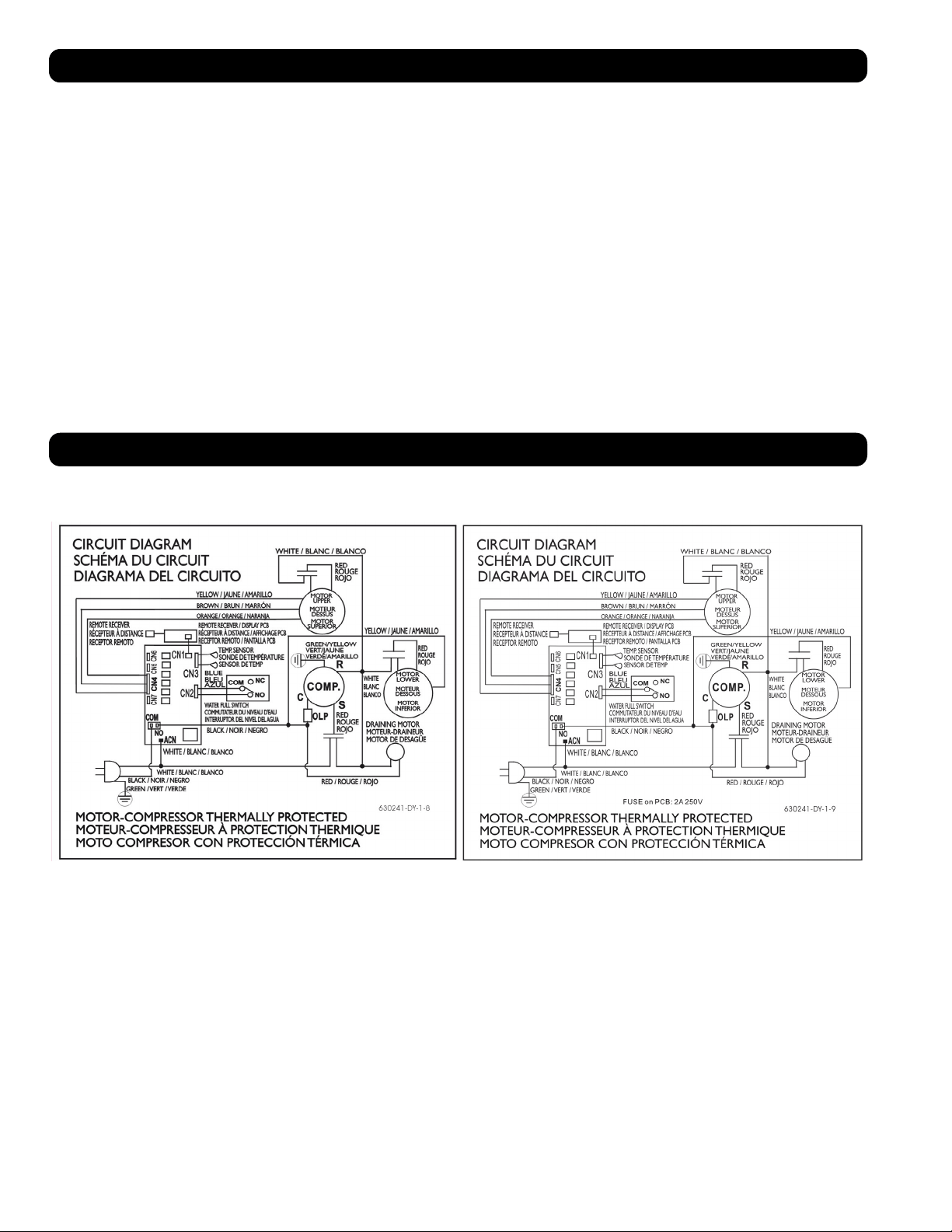
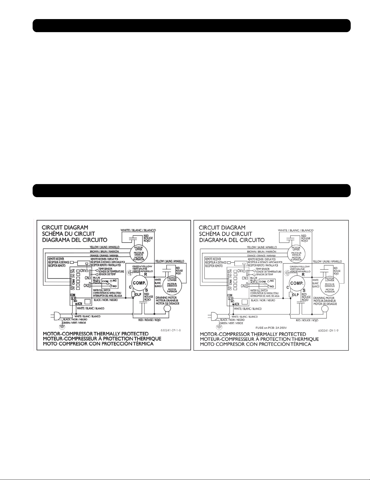
The following diagrams are for reference only. There are no user-serviceable parts inside the unit.
Circuit Diagram, SRCOOL12K Circuit Diagram, SRXCOOL12K, SRXCOOL12KA, SRXCOOL12KB
13
PRODUCT REGISTRATION
Visit tripplite.com/warranty today to register your new Tripp Lite product. You’ll be automatically entered into a drawing for a chance to win a FREE Tripp Lite product!*
* No purchase necessary. Void where prohibited. Some restrictions apply. Open to U.S. residents only. See tripplite.com for details.
Regulatory Compliance Identification Numbers
For the purpose of regulatory compliance certifications and identification, your Tripp Lite product has been assigned a unique series number. The series number can be found on the product nameplate label,
along with all required approval markings and information. When requesting compliance information for this product, always refer to the series number. The series number should not be confused with the
marking name or model number of the product.
WEEE Compliance Information for Tripp Lite Customers and Recyclers (European Union)
Note: This statement applies to products marked with the WEEE logo.
Under the Waste Electrical and Electronic Equipment (WEEE) Directive and implementing regulations, when customers buy new electrical and electronic equipment from Tripp Lite they are
entitled to:
• Send old equipment for recycling on a one-for-one, like-for-like basis (this varies depending on the country)
• Send the new equipment back for recycling when this ultimately becomes waste
Use of this equipment in life support applications where failure of this equipment can reasonably be expected to cause the failure of the life support equipment or to significantly affect its safety or
effectiveness is not recommended.
Tripp Lite has a policy of continuous improvement. Product specifications are subject to change without notice.
Warranty
2-YEAR LIMITED WARRANTY (U.S. and Canada)
1-YEAR LIMITED WARRANTY (All other regions)
Seller warrants this product, if used in accordance with all applicable instructions, to be free from original defects in material and workmanship for a period of 2 years (U.S. and Canada) or 1 year (all other
regions) from the date of initial purchase. If the product should prove defective in material or workmanship within that period, Seller will repair or replace the product, in its sole discretion. Service under
this Warranty can only be obtained by your delivering or shipping the product (with all shipping or delivery charges prepaid) to: Tripp Lite, 1111 W. 35th Street, Chicago, IL 60609 USA. Seller will pay return
shipping charges.
The following limitations apply to the coverage of this warranty. This warranty does not cover:
• Labor charges for installation, setup or training to use the product
• Shipping damage, and any damage caused by improper packaging for shipment to an authorized service center and any damaged caused by improper voltage or other misuse, including abnormal service,
handling or usage
• Cosmetic damage such as scratches and dents
• Normal wear and tear on parts or replacement of parts designed to be replaced, e.g. filters, cartridges, batteries
• Service trips to deliver, pick-up or repair, install the product or to instruct in proper usage of the product
• Damages or operating problems resulting from misuse, abuse, operation outside environmental specifications, uses contrary to instructions provided in the owner’s manual, accidents, acts of God, vermin,
fire, flood, improper installation, unauthorized service, maintenance negligence, unauthorized installation or modification or rental or commercial use
• The use of the product in commercial or rental settings
• Optional accessories, attachments and appearance items
• Products that have been modified to perform outside of specifications
• Products that have had their serial numbers removed or defaced
• Products with serial numbers that have been invalidated
• Damage to personal property from use of the product
• Replacement of repair of facility fuses, circuit breakers, wiring, or plumbing
Warranty and Product Registration
Regulatory Compliance
1111 W. 35th Street, Chicago, IL 60609 USA • tripplite.com/support
20-03-239 93-33FA_RevE
14
Unidad Portátil de Aire Acondicionado
SRCOOL12K – Número de Serie: AG-0073 (120V, 60 Hz)
SRXCOOL12K – Número de Serie: AG-00A0 (230V, 50 Hz)
SRXCOOL12KA – Número de Serie: AG-0533 (230V, 50 Hz)
SRXCOOL12KB – Número de Serie: AG-00A0 (230V, 50 Hz)
Manual del Propietario
Introducción 15
Instrucciones Importantes de Seguridad 15
Características 17
Instalación 18
Operación 22
Limpieza y Mantenimiento 23
Solución de Problemas 24
Almacenamiento y Servicio 25
Diagramas de Circuitos 25
Garantía 26
Cumplimiento de las normas 26
English 1
Français 27
40
1111 W. 35th Street, Chicago, IL 60609 USA • tripplite.com/support
Copyright © 2020 Tripp Lite. Todos los derechos reservados.
SYST
RPS
STAT
DUPLX
SPEED
MODE
1
5
X
3
1
X
3
3
X
4
7
X
5
0
MASTR
STACK
SYST
RPS
STAT
DUPLX
SPEED
MODE
1
5
X
3
1
X
3
3
X
MASTR
STACK
SYST
RPS
STAT
DUPLX
SPEED
MODE
1
5
X
3
1
X
3
3
X
MASTR
STACK
MODE
1
5
X
3
1
X
3
3
X
STACK
4
7
X
5
0
4
7
X
5
0
4
7
X
5
0
4
7
X
5
0
5
0
15
Introducción
La Unidad independiente Portátil de Aire Acondicionado proporciona 12,000 BTU (hasta 3.4 kW) de capacidad complementaria de enfriamiento.
Diseñada para ambientes de TI, es ideal para enfriar gabinetes de rack sobrecalentados, puntos calientes de equipo de TI y gabinetes de
cableado de red sin acceso al aire acondicionado de la instalación. La Unidad Portátil de Aire Acondicionado puede enfocar aire frío mediante
su ducto flexible de enfriamiento o enfriar una sala pequeña a través de su ventila con persianas. Además filtra y seca el aire para mejorar las
condiciones de operación y confiabilidad del equipo. El condensado es re-evaporado para una operación libre de goteo, de modo que usted no
gaste tiempo vaciando los tanques colectores de agua. El diseño independiente no requiere plomería o circuitos especiales, de modo que la
instalación es rápida y fácil. El refrigerante ecológico R410A cumple con los estándares ambientales internacionales.
Aplicaciones Recomendadas
Instrucciones de seguridad importantes
GUARDE ESTAS INSTRUCCIONES
Este manual contiene instrucciones y advertencias que deben seguirse durante la instalación, el
funcionamiento y el almacenamiento de este producto. Si no tiene en cuenta estas advertencias se
puede anular la garantía.
Advertencias
• Antes de usar este dispositivo, cada usuario debe determinar si es apto, adecuado o seguro para el uso que pretende darle. Dado que las
aplicaciones individuales están sujetas a diversas variaciones, el fabricante no representa ni garantiza la idoneidad o condición de este
dispositivo para cualquier aplicación específica.
• Instale la unidad en interiores, alejada de temperaturas o humedad extremas, la luz solar directa, polvo y contaminantes conductores.
• Deje espacio adecuado para ventilación alrededor de la unidad, con la parte posterior y costados ventilados a no menos de 51 cm [20
pulgadas] de paredes u otros obstáculos.
• Instale la unidad sobre una superficie plana con una inclinación no mayor de 10º.
• Conecte la unidad a un tomacorriente de CA conectado directamente a tierra. La omisión en esto puede originar una descarga eléctrica o un incendio.
• Esta unidad está diseñada para suministrar enfriamiento complementario para puntos calientes localizados.
• La alimentación de energía para la unidad debe estar especificada de acuerdo con la placa de identificación de la unidad.
• No modifique la clavija ni utilice un adaptador que elimine la conexión a tierra.
• No utilice cables de extensión para conectar la unidad a un tomacorriente de CA. Use sólo el cable de alimentación suministrado con la unidad.
• Cumpla todos los reglamentos aplicables de cableado y seguridad, como el Código Eléctrico Nacional (NEC) en los EE.UU.
• No enchufe equipo adicional en el tomacorrientes en donde esté conectada la unidad. La sobrecarga del tomacorriente puede causar una
descarga eléctrica o un incendio.
• No intente encender o apagar la unidad conectando o desconectando el enchufe de CA. Puede ocurrir una severa descarga eléctrica. Use el
botón de ON/OFF para encender y apagar la unidad.
• Apague la unidad y desenchúfela del tomacorrientes de CA antes de realizar el mantenimiento.
• Antes de conectar la unidad a un sistema de drenaje dedicado, apague la unidad y desenchúfela. Existe un riesgo de descarga eléctrica
cuando la unidad está enchufada.
• No use adelgazantes, alcohol, detergentes o cepillos abrasivos para limpiar el gabinete de la unidad. Estos artículos pueden dañar el gabinete.
• No vierta agua sobre la unidad. Esto puede causar una descarga eléctrica y dañar la unidad.
• No opere la unidad sin el filtro de aire. Esto puede causar una acumulación de polvo que puede dañar la unidad.
• No intente operar la unidad en un cuarto con circulación inadecuada de aire. Proporcione aire complementario de acuerdo con los códigos de
construcción aplicables.
• No coloque objetos en la parte superior de la unidad.
• No opere su aire acondicionado en una habitación húmeda, como un baño o la lavandería.
• El rango de temperatura de operación aplicable para esta unidad es de 17°C-35°C (solo modelos SRX).
1. Enfriamiento de un gabinete de rack
sobrecalentado.
2. Enfriamiento de un punto caliente de
equipo dentro o fuera de un gabinete de
rack.
3. Enfriamiento de una sala pequeña.

16
Instrucciones de seguridad importantes
• Este aparato no debe ser utilizado por personas (incluidos niños) con facultades físicas, sensoriales o mentales reducidas o que carezcan de
experiencia y conocimientos, a menos que la persona responsable por su seguridad los haya supervisado o les haya dado instrucciones para
el uso del aparato.
• Se debe supervisar que los niños no jueguen con el aparato.
• No se recomienda usar este equipo en aplicaciones de mantenimiento artificial de la vida, donde se puede esperar razonablemente que su
falla cause la falla del equipo de mantenimiento de la vida o que afecte de manera importante su seguridad o eficiencia. No use este equipo
en presencia de mezclas anestésicas inflamables con aire, oxígeno u óxido nitroso.
A
ABF C D I
GH
E F
B
B
M
N
D
C
L
G
H K
I
F J
E E
17
Características
Vista Frontal
A
Panel de Control
B
Manijas Empotradas
C
Cubiertas del Filtro de Aire
D
Salida del Drenaje
E
Ruedas
F
Panel Frontal
G
Salida de Aire Frío
H
Inserto de Ventilación con Persiana
(Pre-Instalado)
I
Adaptador de Ducto de Enfriamiento
(Opcional)
J
Panel Posterior
K
Descarga de Aire Caliente
L
Salida de Drenaje del Evaporador
M
Filtro del Evaporador
N
Filtro del Condensador
Panel de Control
A
Botón “POWER” [encendido]
B
Botón “FUNCTION” [función]
C
Botón “TIMER” [temporizador]
D
Botón “FAN SPEED”
[velocidad del ventilador]
E
Botón “QUIET”
[modo de control silencioso]
F
Botones de Control de Temperatura
G
Pantalla Numérica
H
LEDs de Modo de Operación
I
LEDs de Modo de Velocidad del Ventilador

≥ 51 cm (20 pulg.)
≥ 51 cm (20 pulg.)
PARED
PARED
645 cm
2
(100 pulg.
2
)
Vent (Para Espacios
Limitados)
1
2-1
2-2
A
A
18
Instalación
Advertencia: Después de retirar la unidad del contenedor de embarque, compruebe para detectar daños o partes faltantes.
(Consulte la siguiente lista de partes.) Si detecta un problema, visite tripplite.com/support para solicitar servicio. No intente operar
una unidad dañada.
Lista de Piezas Accesorias:
1
Ubicación de Unidad
Coloque la unidad sobre una superficie plana, nivelada próxima a un tomacorrientes de CA con
conexión a tierra dimensionado de acuerdo con la placa de identificación de la unidad (90 a
110 % de la tensión especificada). Deje espacio adecuado para ventilación alrededor de la
unidad, con la parte posterior y costados ventilados a no menos de 51 cm [20 pulgadas] de
paredes u otros obstáculos. Coloque la unidad con acceso cómodo a un falso plafón o ventana
para proporcionar la ruta más recta y corta disponible para el ducto flexible de descarga. Si
planea usar el ducto flexible de enfriamiento para concentrar el aire frío en un gabinete de rack
o dispositivo específico, coloque la unidad próxima al gabinete de rack o dispositivo señalado
para proporcionar la ruta más recta y corta posible para el ducto de enfriamiento.
Advertencia: No utilice cables de extensión para conectar la unidad a un
tomacorriente de CA. Use sólo el cable de alimentación suministrado con la
unidad.
Nota: Si la unidad funcionará en un espacio reducido (como un armario), debe suministrar
aire suplementario a fin de mantener la eficiencia del flujo de aire. Una ventila de 645 cm
2
(100 pulg
2
) o mayor instalada cerca de la parte inferior de la puerta debe suministrar aire
complementario adecuado para un armario típico. Para obtener más información, consulte los
códigos de construcción aplicables.
No se muestra manguera de descarga—vea la Sección 3.
2
Conexión del Ducto de Enfriamiento (Opcional)
El inserto de la ventila con persiana preinstalado es apropiado para aplicaciones de
enfriamiento de salas. Si planea enfriar una sala, salte el paso 2 y proceda al paso 3. Si planea
usar el ducto de enfriamiento para dirigir el aire de enfriamiento a un dispositivo o gabinete de
rack específico, siga las instrucciones siguientes.
2-1
Desmonte el inserto de ventila con persiana
A
jalándolo hacia afuera y hacia arriba.
Tubo de
Descarga
(Tubo Mayor)
Tubo de
Enfriamiento
(Tubo Menor)
Adaptador de Tubo
de Descarga
Panel Ajustable de
Descarga
(2 Secciones)
Tornillo Autoroscante 2 Adaptador
del Ducto de
Enfriamiento
(1 Preinstalado)
Inserto de Ventila
con Persiana
(Preinstalado)
2-2
Alinee el adaptador del ducto de enfriamiento
A
en la abertura de la ventila y empújelo
hacia abajo hasta que asegure en su lugar.
1
2
1
2
1
2
2-3
2-4
3-1
3-2
A
A
B
B
A
B
19
2-3
Conecte el ducto flexible de enfriamiento (el tubo menor
A
) al adaptador del tubo de
enfriamiento
B
. Alinee el ducto con la abertura del adaptador circular, empuje el ducto
hacia abajo y gire el ducto en sentido de las manecillas del reloj hasta que atornille
sólidamente en el adaptador.
Instalación
2-4
Coloque el otro extremo del ducto de enfriamiento cerca de la entrada de aire del
dispositivo o gabinete de rack en cuestión, usando la ruta más recta y corta posible Si
planea enfriar un gabinete de rack, coloque el extremo del ducto de enfriamiento sobre un
área perforada cerca de la parte superior de la puerta frontal del gabinete (o cerca de la
parte superior del banco de equipo que requiera enfriamiento). El aire frío descenderá y se
distribuirá a través del aire entrante en el frente del gabinete de rack.
3
Conexión del Ducto de Descarga
3-1
Conecte el ducto flexible de descarga (el tubo mayor
A
) a la ventila de descarga del aire
caliente en el panel posterior de la unidad
B
. Alinee el ducto con la abertura de la ventila
circular, empuje el ducto hacia adentro y gire el ducto en sentido de las manecillas del
reloj hasta que atornille sólidamente en la ventila de descarga.
3-2
Conecte el otro extremo del ducto d descarga
A
al adaptador del ducto de descarga
B
Alinee el ducto con la abertura del adaptador circular, empuje el ducto hacia adentro y
gire el ducto en sentido de las manecillas del reloj hasta que atornille sólidamente en el
adaptador.
Si planea conectar el ducto de descarga a un falso plafón, proceda al paso
4
. Si planea
conectar el ducto de descarga a una ventana, proceda al paso
5
.
Tornillo Autoroscante
Tornillo Autoroscante
4-1
5-1
4-2
5-2
4-3
4-4
Panel de Plafón
(Desde Abajo)
Panel de Plafón
(Desde Arriba)
Panel de Descarga
20
Instalación
4
Conexión de Descarga de Falso Plafón
Advertencia: Algunos plafones pueden requerir procedimientos de instalación
modificados. El usuario debe determinar la aptitud de los accesorios y los
procedimientos antes de la instalación. Los procedimientos descritos en este
manual pueden no ser apropiados para todas las aplicaciones.
4-1
Elija un panel desmontable del falso plafón próximo a la unidad para proporcionar la ruta
más recta y corta posible para el ducto flexible de descarga. Mida el ancho del panel
del plafón, incluyendo la porción que descansa en la rejilla del plafón. Combine las dos
secciones del panel ajustable de descarga, ajuste entonces el panel de descarga para
coincidir con el panel del plafón. Después que el panel de descarga se ajuste al ancho
correcto, use use el tornillo autorroscante incluido para asegurarlo en su sitio.
Nota: El panel de escape puede ajustarse desde 52.1 cm hasta 104.1 cm [20.5 a 49.2
pulgadas]. Algunas instalaciones pueden necesitar recortar el panel de escape para un
ajuste correcto.
4-2
Inserte el adaptador del ducto de descarga en el agujero oblongo en el panel de descarga
ajustable. El adaptador se fijará en su lugar..
4-3
Deslice el panel del plafón a un lado y coloque el panel de descarga dentro del espacio en
el plafón. Permita que el panel de descarga descanse en la parte superior de la rejilla del
plafón.
Nota: Debe haber al menos un espacio abierto de 10 pulgadas (25.4 cm) sobre el panel
de descarga para permitir el flujo adecuado de aire.
4-4
Deslice el panel de plafón de regreso a su sitio de modo que se junte con el panel de
descarga y cierre cualquier abertura en el plafón. Un sello hermético permitirá la máxima
eficiencia de enfriamiento. Si la instalación es permanente, recorte el panel del plafón de
modo que no traslape la rejilla del plafón.
Nota: El ducto flexible de descarga puede ampliarse a una longitud máxima de 118
pulgadas (300 cm). Proporcione la ruta más recta y corta posible. El doblado o estirado
excesivo del ducto reducirá la eficiencia de enfriamiento.
Después de terminar el paso
4
, proceda al paso
6
.
5
Conexión de Descarga de Ventana
Advertencia: Algunas ventanas pueden requerir procedimientos de instalación
modificados. El usuario debe determinar la idoneidad de los accesorios y los
procedimientos antes de la instalación. Los procedimientos descritos en este
manual pueden no ser apropiados para todas las aplicaciones.
5-1
Mida la abertura de la ventana. Combine las dos secciones del panel ajustable de
descarga, ajuste entonces el panel de descarga para coincidir con la abertura de la
ventana. Después que el panel de descarga se ajuste al ancho correcto, use use el tornillo
autorroscante incluido para asegurarlo en su sitio.
Nota: El panel de descarga puede ajustarse de 52.1 a 104.1 cm (20.5 a 49.2
pulgadas). Es compatible con instalación vertical y horizontal.
5-2
Inserte el adaptador del ducto de descarga en el agujero oblongo en el panel de descarga
ajustable. El adaptador se fijará en su lugar.
Abertura Horizontal
de Ventana
Abertura
Vertical de
Ventana
INCORRECTO CORRECTO
5-3
6-1
6-2
6-3
AL DRENAJE
AL DRENAJE
21
Instalación
5-3
Inserte el panel de descarga en la abertura de la ventana, cierre entonces la ventana
contra el panel de descarga. Un sello hermético permitirá la máxima eficiencia de
enfriamiento. Nota: Debe haber al menos un espacio abierto de 10 pulgadas (25.4 cm)
detrás del panel de descarga para permitir el flujo adecuado de aire.
Nota: El ducto flexible de descarga puede ampliarse a una longitud máxima de 118
pulgadas (300 cm). Proporcione la ruta más recta y corta posible. El doblado o estirado
excesivo del ducto reducirá la eficiencia de enfriamiento.
6
Inserción del Tapón de Drenaje
Advertencia: El re-evaporador integrado de la unidad no funcionará hasta que
usted inserte el tapón de drenaje en la salida de drenaje.
Cuando la unidad enfría o deshumedece, se forma condensación. La unidad tiene un re-
evaporador integrado que le permite expulsar la condensación a través de la corriente de
aire caliente de descarga. Esta característica permite a la unidad operar indefinidamente sin
requerir el vaciado de un tanque recolector de agua. La unidad se embarca con los tapones de
drenaje superior e inferior instalados.
6-1
Modo de Enfriamiento con Re-evaporación
Ambos tapones deben permanecer instalados para permitir la re-evaporación de la
condensación.
6-2
Modo de Enfriamiento sin Re-evaporación
Para usar el modo de Enfriamiento sin re-evaporar la condensación, retire el tapón de
drenaje inferior y conduzca la tubería de drenaje suministrada por el usuario a un drenaje
externo. El tapón del drenaje superior debe permanecer instalado.
6-3
Modo de Deshumidificado
Al usar la unidad en el modo de Deshumidificado, retire el tapón del drenaje superior y
conduzca la tubería de drenaje suministrada por el usuario a un drenaje externo. El tapón
del drenaje inferior debe permanecer instalado. Esto maximizará la cantidad de agua
eliminada del aire.
Nota: Si el sistema de drenaje se obstruye, un pequeño recipiente interno recolectará
la condensación. Si no se despeja el sistema de drenaje antes que se llene el recipiente
interno, la unidad se apagará automáticamente.
Advertencia: Antes de conectar la unidad a un sistema de drenaje dedicado,
apague la unidad y desenchúfela. Existe un riesgo de descarga eléctrica
cuando la unidad está enchufada.
Nota: Si el sistema de enfriamiento de su edificio tiene configuraciones de termostato nocturnas o de fin de semana, tiene apagados
periódicos o tiene una capacidad limitada de enfriamiento, usted puede tener que considerar alternativas para la instalación estándar. Este
producto está pensado para usarse como dispositivo de enfriamiento complementario y no puede adecuarse a fluctuaciones significativas
en temperatura o humedad del edificio.
Operación a Baja Temperatura
El acondicionador de aire es un enfriador de alto rendimiento, capaz de producir una salida de aire muy frío. Al usar la unidad en ambientes
que ya están fríos (20° C / 68° F o menos), Tripp Lite recomienda el uso del modo de sólo deshumidificar. Esto permitirá a la unidad continuar
proporcionando el enfriamiento complementario mientras evita cualquier problema de congelamiento del evaporador causado por la baja
temperatura en la sala.
22
Operación
Advertencia: Instale la unidad de acuerdo a las instrucciones en la sección de “Instalación” antes de intentar operarla.
Encendido
Encienda o apague la unidad oprimiendo el botón “POWER” [Encendido].
La unidad tiene un retraso del compresor de tres minutos a fin de evitar posibles sobrecargas del
circuito al arranque.
Característica de Reinicio Automático
La unidad encenderá y reasumirá la operación automáticamente cuando se restablezca la energía
después de un apagón. La unidad usará los mismos parámetros que usaba inmediatamente antes
de ocurrir el apagón. Nota: Si el apagón es breve, la unidad hará funcionar sólo el ventilador por tres
minutos antes de reasumir la operación normal. El retraso permite despresurizar el compresor de modo
que la unidad funcione correctamente cuando ingrese al modo de enfriamiento.
Modo de Enfriamiento
Al Oprimir el botón “FUNCTION” se conmuta entre el modo de enfriamiento y el modo de
deshumidificado. Cuando está activo el modo de enfriamiento se enciende el LED “COOLING”.
Oprima los botones TEMP+ y TEMP- para establecer la temperatura en el modo de enfriamiento. La
temperatura seleccionada se muestra en la pantalla numérica. Una vez establecida, la temperatura
deseada destellará cinco veces después de lo cual la pantalla mostrará la temperatura actual de la sala.
Oprima el borón “FAN SPEED” para conmutar entre las velocidades alta, media y baja del ventilador.
Se enciende un LED para indicar la velocidad seleccionada del ventilador. Cuando se selecciona la
velocidad en AUTO, la unidad seleccionará automáticamente una velocidad del ventilador en función
de las temperaturas programada y ambiente. Si la temperatura ambiente es inferior a la temperatura
establecida, el ventilador funcionará y el LED “COOLING” destellará para indicar que el compresor está
apagado. Cuando se reinicia el enfriamiento, el LED “COOLING” permanecerá encendido.
Modo de Deshumidificado
Al Oprimir el botón “FUNCTION” se alterna entre el modo de enfriamiento y el modo de deshumidificado.
Cuando está activo el modo de deshumidificado se enciende el LED “DEHUMIDIFY”. En el modo
de deshumidificado, el ventilador funciona a una velocidad fija y los controles de temperatura son
irrelevantes. Para un desempeño óptimo en el modo de deshumidificado, cierre puertas y ventanas,
retire el tapón del drenaje superior y conduzca la tubería de drenaje suministrada por el usuario a un
drenaje externo.
Temporizador
El botón “TIMER” le permite programar la unidad para encender o apagar automáticamente.
Encendido Programado (Nota: La unidad debe estar apagada para activar la función de Encendido
Programado. Confirme que los parámetros de modo, temperatura y velocidad del ventilador estén
correctos antes de activar la función de encendido programado). Active el temporizador oprimiendo el
botón “TIMER”. Oprima los botones TEMP+ y TEMP- para configurar la demora (en horas) antes de que
la unidad se encienda. El número de horas se muestra en la pantalla numérica. El número destellará
cinco veces en la pantalla antes de regresar a la temperatura actual.
Apagado Programado (Nota: La unidad debe estar encendida para programar la función de apagado
programado). Active el temporizador oprimiendo el botón “TIMER”. Oprima los botones TEMP+ y
TEMP- para configurar la demora (en horas) antes de que la unidad se apague. El número de horas se
muestra en la pantalla numérica. El número destellará cinco veces en la pantalla antes de regresar a la
temperatura actual.
Modo de Control Silencioso
La unidad incluye un modo de Control Silencioso que regula el enfriamiento mediante el temporizador
y el microprocesador para conseguir niveles de operación más silenciosos, cuando el ruido sea un
problema.
Para activarlo, oprima el botón “QUIET”. Se encenderá el LED Quiet. Seleccione la temperatura deseada
y entonces ajuste el temporizador para la duración del ciclo de Control de Silencioso. Durante el curso
del ciclo, la memoria del microprocesador ajustará la temperatura predeterminada en 0.5° C (0.9° F)
cada 30 minutos hasta que alcance la temperatura deseada. Una vez alcanzada la temperatura, la
unidad mantendrá la temperatura por la duración del tiempo establecido.
A
A
23
Operación
Limpieza y Mantenimiento
Limpie la unidad de aire acondicionado y limpie o reemplace los filtros regularmente para maximizar el rendimiento y la eficiencia, prolongar la
vida útil de la unidad y calificar para la garantía si hay un problema de rendimiento.
Nota: Siempre desconecte la unidad de aire acondicionado del tomacorriente antes de limpiarlo.
Limpieza de los Filtros de Aire
Es importante mantener los filtros de aire limpios y libres de polvo. Cuando los filtros están sucios u obstruidos con polvo, se reduce la eficiencia
de enfriamiento y se puede amenazar la calidad del aire. Tripp Lite recomienda la limpieza de los filtros al menos una vez cada dos semanas. Si
la unidad se usa en un ambiente polvoriento, es posible que los filtros deban limpiarse o reemplazarse semanalmente.
¡Antes de la limpieza de los filtros, apague la unidad y desenchúfela! Existe un riesgo de descarga eléctrica cuando la
unidad está enchufada.
Nunca opere la unidad de aire acondicionado sin el filtro.
1. Apague la unidad y desenchúfela.
2. Desmonte los filtros
A
deslizándolos fuera del gabinete.
3. Use una aspiradora o golpee ligeramente el filtro para eliminar polvo y suciedad sueltos.
4. Lave los filtros con agua caliente con un detergente neutro. No coloque los filtros en una
lavatrastos ni use detergentes o químicos agresivos. Permita que los filtros se sequen al aire
completamente después del lavado.
Nota: Para limpiar los filtros no utilice agua más caliente de 40° C (104° F).
5. Recoloque los filtros deslizándolos nuevamente en su posición original.
6. Enchufe la unidad y restablezca la operación normal.
Limpieza del Gabinete
¡Antes de la limpieza del gabinete, apague la unidad y desenchúfela! Existe
un riesgo de descarga eléctrica cuando la unidad está enchufada.
1. Apague la unidad y desconéctela.
2. Para limpiar el gabinete use un paño seco, no abrasivo. Si es necesario, use agua tibia tibia para humedecer el paño. Nunca use químicos
abrasivos, sustancias volátiles, gasolina, benceno, thiner, detergentes, paños tratados químicamente u otros químicos agresivos o solventes
de limpieza que pueden dañar el exterior del gabinete. No vierta agua directamente sobre la unidad o dentro de las partes de trabajo. Esto
causa un riesgo de descarga eléctrica y deterioro de componentes eléctricos y en el aislamiento del cableado.
3. Use un cepillo de cerdas suaves para limpiar entre las ventilas.
4. Use con cuidado una aspiradora para limpiar los serpentines del condensador.
Cambio de Unidades de Grados
El SRCOOL12K puede mostrar la temperatura en unidades Celsius y Fahrenheit. El
parámetro predeterminado para el SRCOOL12K es Fahrenheit y la SRXCOOL12K/
SRXCOOL12KA/SRXCOOL12KB es Celsius.
Para cambiar entre unidades, coloque el SRCOOL12K en modo de espera. La Unidad de Aire
Acondicionado está en modo de espera cuando es enchufado a la energía de CA, pero está
apagado. Después, sostenga la tecla “FUNCTION” por 10 segundos. Para verificar el grado
en que han cambiado las unidades, encienda la unidad.
Alarma
Cuando el tanque de agua esté lleno, la unidad mostrará el mensaje “E4” en la pantalla.
Para restablecer el funcionamiento normal, apague la unidad, retire el tapón del drenaje y
vacíe el exceso de agua de la unidad. Coloque el tapón y encienda la unidad para iniciar el
enfriamiento.
24
Solución de Problemas
Revise las posibles soluciones a continuación. Si persiste el problema, visite por favor tripplite.com/support para solicitar servicio.
Problema Causa posible Solución posible
La unidad no funciona. La unidad está apagada. Encienda la unidad. Consulte la sección “Operación”.
La unidad no está enchufada. Enchufe la unidad en un tomacorrientes adecuado.
La alimentación principal está apagada. Compruebe los fusibles o disyuntores.
El rendimiento del
enfriamiento no es
satisfactorio.
Está bloqueada la entrada o la descarga de aire. Confirme que todos los ductos y entradas estén libres de obstrucciones.
La calibración de temperatura es demasiado alta. Ajuste el parámetro de temperatura.
La calibración de velocidad del ventilador es demasiado baja. Ajuste el parámetro del ventilador.
Los filtros de aire están sucios Limpie los filtros de aire.
La potencia del gabinete de rack, el tamaño de la sala o la temperatura
ambiente excede la capacidad de enfriamiento de una sola unidad.
Instale unidades adicionales o póngase en contacto con Tripp Lite para consultar soluciones de
enfriamiento adicional adecuadas para su aplicación.
La unidad gotea agua. El tapón de drenaje no está instalado. Instale el tapón de drenaje en la salida del drenaje. Consulte la sección “Instalación”.
La unidad genera ruido o
vibración excesivos.
La unidad está sobre una superficie dispareja o inestable. Mueva la unidad a una superficie nivelada y estable.
La unidad tiene
acumulación de hielo o
escarcha.
La unidad esté operando en un entorno con humedad excesiva. OPCIÓN 1: Apague la unidad y déjela descongelarse. Una vez descongelada, cerciórese que la unidad
esté operando con la velocidad del ventilador en ALTA.
OPCIÓN 2: Apague la unidad y déjela descongelarse. Una vez descongelada, opere la unidad en
MODO DE DESHUMIDIFICADO o aumente la selección de la temperatura deseada.
Códigos Adicionales de Pantalla
Códigos de Error
El SRCOOL12K/SRXCOOL12K/SRXCOOL12KA/SRXCOOL12KB de Tripp Lite tiene la capacidad de auto-monitorearse continuamente. Si ocurriere
un error, la pantalla mostrará uno de los 5 códigos de error siguientes:
Código de
Error Descripción
E0 Error de Comunicación Interna
E1 Error del Sensor de Temperatura en
Interiores
E2 Error del Sensor de Temperatura
Interna
E3 Error de Refrigerante
E4 Lleno de Agua
El código E4 puede borrarse vaciando el tanque de agua. Para detalles, consulte la entrada de
alarma en la sección de Operación.
Para los Códigos E0, E1, E2 y E3 siga estos pasos:
1. Apague la unidad desconectándola de la alimentación durante 5 minutos.
2. Enchufe nuevamente la unidad.
3. Arranque la unidad.
Si el código permanece borrado, continúe operando normalmente la unidad. Si el código
reaparece, póngase por favor en contacto con Tripp Lite para obtener instrucciones adicionales.
Código dF
Se mostrará “dF” cuando el SRCOOL12K/SRXCOOL12K/SRXCOOL12KA/SRXCOOL12KB detecte una condición en la que el serpentín esté
operando debajo de 1° C (33.8° F) por más de 15 minutos.
Durante un evento de código dF, los ventiladores de la unidad funcionarán sin el compresor para evitar que se congele el evaporador. Una vez
que la temperatura del serpentín sea superior a 1° C (33.8° F), el compresor reiniciará la operación normal.
Si persiste esta condición, la unidad está operando en un ambiente demasiado frío. Tripp Lite recomienda que la unidad opere solo en modo de
Deshumidificación si opera a temperaturas inferiores a 20° C (68° F). Para más información, vea Operación a Baja Temperatura en la sección
6-3.
25
Almacenamiento y servicio
Almacenamiento
Antes de almacenar la unidad, confirme que los ductos y ventilas estén asegurados o desmontados y protegidos adecuadamente. Confirme
además que la unidad está libre de condensado.
Servicio
Su producto Tripp Lite está cubierto por la garantía descrita en este manual. Tripp Lite también pone a disposición una variedad de garantías
extendidas y programas de servicio en el sitio. Para obtener más información sobre mantenimiento, visite tripplite.com/support. Antes de enviar
el producto a mantenimiento, siga estos pasos:
1. Revise los procedimientos de instalación y operación descritos en este manual para asegurarse de que el problema de servicio no se origina
en una mala comprensión de las instrucciones.
2. Si el problema continúa, no se comunique ni devuelva el producto al distribuidor. En su lugar, visite tripplite.com/support.
3. Si el problema requiere servicio, visite tripplite.com/support y haga clic en el enlace Devolución de productos. Aquí puede solicitar un número
de autorización de devolución de mercadería (RMA), que es necesario para el servicio. En este simple formulario en línea se le pedirá el
modelo y números de serie de su unidad, junto con otra información general sobre el comprador. El número RMA y las instrucciones para el
envío se le enviarán por correo electrónico. Esta garantía no cubre ningún daño (directo, indirecto, especial o consecuencial) que el producto
sufra durante el envío a Tripp Lite o un centro de servicio autorizado por Tripp Lite. Los productos que se envían a Tripp Lite o un centro de
servicio autorizado por Tripp Lite debe tener prepagos los cargos de envío. Escriba el número RMA en el exterior del paquete. Si el producto se
encuentra dentro del período de garantía, adjunte una copia del recibo de venta. Envíe el producto para servicio a través de un transportador
asegurado a la dirección que se le proporcione cuando solicite el RMA.
Diagramas de Circuitos
Los siguientes diagramas son solo para fines de consulta. No hay partes dentro de la unidad a las que el usuario pueda dar servicio.
Diagrama de Circuito, SRCOOL12K Diagrama de Circuito, SRXCOOL12K, SRXCOOL12KA, SRXCOOL12KB
26
Garantía
GARANTÍA LIMITADA POR 2 AÑOS (EE UU y Canadá)
GARANTÍA LIMITADA POR 1 AÑO (todas las demás regiones)
El vendedor garantiza este producto, si se usa de acuerdo con todas las instrucciones aplicables, de que está libre de defectos en material y mano de obra por un período de 2 años (EE UU y Canadá) o
1 año (todas las otras regiones) a partir de la fecha de compra inicial. Si el producto resultara defectuoso en material o mano de obra dentro de ese período, el vendedor reparará o reemplazará el producto
a su entera discreción. El servicio bajo esta garantía sólo puede obtenerse entregando o embarcando el producto (con todos los cargos de envío o embarque prepagados) a: Tripp Lite, 1111 W. 35th Street,
Chicago, IL 60609 EE UU. El vendedor reembolsará los cargos de envío.
Las siguientes limitaciones se aplican a la cobertura de esta garantía. Esta garantía no cubre:
• Cargos por mano de obra para instalación, configuración o capacitación para usar el producto
• Daño por envío y cualquier daño causado por empaque inadecuado para envío a un centro de servicio autorizado y cualquier daño causado por voltaje inadecuado u otro mal uso, incluyendo servicio,
manejo o uso anormal
• Daños cosméticos como arañazos y abolladuras
• Desgaste normal en piezas o reemplazo de piezas diseñadas para ser reemplazadas, por ejemplo filtros, cartuchos, baterías
• Viajes de servicio para entregar, recoger o reparar, instalar el producto o para instruir en el uso adecuado del producto
• Daños o problemas de operación resultantes del mal uso, abuso, operación fuera de especificaciones ambientales, usos contrarios a las instrucciones proporcionadas en el manual del propietario,
accidentes, actos de Dios, fauna nociva, incendio, inundación, instalación incorrecta, servicio no autorizado, negligencia en el mantenimiento, instalación o modificación no autorizada o uso comercial o
de alquiler
• El uso del producto en ambientes comerciales o de alquiler
• Accesorios opcionales, accesorios y artículos de apariencia
• Productos que han sido modificados para funcionar fuera de las especificaciones
• Productos a los que se les han quitado o dañado sus números de serie
• Productos con números de serie que han sido invalidados
• Daño a la propiedad personal por uso del producto
• Reemplazo o reparación de fusibles, breakers, cableado o plomería de la instalación
Garantía
Cumplimiento de las normas
1111 W. 35th Street, Chicago, IL 60609 USA • tripplite.com/support
Conformidad con las regulaciones sobre números de identificación
Con el objeto de cumplir con las regulaciones de certificaciones e identificación, a su producto Tripp Lite se le ha asignado un número de serie único. Puede encontrar el número de serie en la etiqueta o
placa de identificación del producto, junto con todas las marcas de aprobación e información necesarias. Cuando solicite información de cumplimiento de este producto, siempre haga referencia al número
de serie. El número de serie no debe confundirse con el nombre de marca o el número de modelo del producto.
Información de cumplimiento con WEEE para los clientes y recicladores de Tripp Lite (Unión Europea)
Nota: Esta declaración aplica a productos marcados con el logotipo WEEE.
Bajo la Directiva de Residuos de Aparatos Eléctricos y Electrónicos (WEEE) y las reglamentaciones reguladoras, cuando los clientes compran cualquier equipo eléctrico y electrónico nuevo de
Tripp Lite tienen derecho a:
• Enviar el equipo viejo para reciclaje de uno a uno, y que sean comparables (esto varía según el país)
• Enviar el equipo nuevo para reciclaje cuando se transforma en desecho
El uso de este equipo en aplicaciones de soporte de vida en donde la falla de este equipo pueda razonablemente hacer suponer que causará fallas en el equipo de soporte de vida o afecte
significativamente su seguridad o efectividad, no está recomendado.
Tripp Lite tiene la política de mejora continua. Las especificaciones del producto están sujetas a cambios sin notificación previa.
20-03-239 93-33FA_RevE
27
Climatiseur portatif
SRCOOL12K – Numéro de série : AG-0073 (120V, 60 Hz)
SRXCOOL12K – Numéro de série : AG-00A0 (230V, 50 Hz)
SRXCOOL12KA – Numéro de série : AG-0533 (230V, 50 Hz)
SRXCOOL12KB – Numéro de série : AG-00A0 (230V, 50 Hz)
Manuel du propriétaire
Introduction 28
Consignes de sécurité importantes 28
Caractéristiques 30
Installation 31
Fonctionnement 35
Nettoyage et maintenance 36
Dépannage 37
Entreposage et service 38
Schémas des circuits 38
Garantie 39
Conformité aux règlements 39
English 1
Español 14
40
1111 W. 35th Street, Chicago, IL 60609 USA • tripplite.com/support
Copyright © 2020 Tripp Lite. Tous droits réservés.
SYST
RPS
STAT
DUPLX
SPEED
MODE
1
5
X
3
1
X
3
3
X
4
7
X
5
0
MASTR
STACK
SYST
RPS
STAT
DUPLX
SPEED
MODE
1
5
X
3
1
X
3
3
X
MASTR
STACK
SYST
RPS
STAT
DUPLX
SPEED
MODE
1
5
X
3
1
X
3
3
X
MASTR
STACK
MODE
1
5
X
3
1
X
3
3
X
STACK
4
7
X
5
0
4
7
X
5
0
4
7
X
5
0
4
7
X
5
0
5
0
28
Introduction
Le climatiseur portatif autonome fournit 12 000 BTU (jusqu’à 3,4 kW) de capacité de refroidissement supplémentaire. Conçu pour les
environnements TI, il est idéal pour le refroidissement des armoires de bâti surchauffées, les points sensibles de l’équipement TI et les armoires
de réseau n’ayant pas accès à la climatisation de l’établissement. Le climatiseur portatif peut concentrer l’air froid à travers son conduit
de refroidissement flexible ou refroidir une petite pièce par le biais de son évent à lames. Il peut également filtrer et déshumidifier l’air afin
d’améliorer les conditions de fonctionnement et la fiabilité de l’équipement. Le condensat est de nouveau évaporé pour un fonctionnement
antigoutte de façon à ce que vous n’ayez pas à perdre du temps à vider des réservoirs de cueillette. La conception autonome n’exige
aucune plomberie ou circuits spéciaux, l’installation est donc facile et rapide. Le fluide frigorigène R410A écologique satisfait aux normes
environnementales partout à travers le monde.
Applications recommandées :
Consignes de sécurité importantes
CONSERVEZ CES INSTRUCTIONS
Ce manuel contient des instructions et des avertissement qui doivent être observés durant l’installation,
l’utilisation et l’entreposage de ce produit. le non respect de ces avertissements peut affecter votre garantie.
Avertissements
• Avant d’utiliser cet appareil, l’utilisateur individuel doit déterminer s’il est approprié, adéquat et sécuritaire pour l’utilisation prévue. Puisque
les applications individuelles sont sujettes à d’importantes variations, le fabricant ne prétend ni ne garantit aucunement que cet appareil est
approprié ou apte pour toute application spécifique.
• Installez l’appareil à l’intérieur, à l’écart des températures extrêmes et de l’humidité, de la lumière directe du soleil, de la poussière et des
contaminants conducteurs.
• Laissez un espace suffisant autour de l’appareil pour garantir une bonne circulation d’air, avec l’arrière et les côtés ventilés à au moins 51 cm
(20 pouces) des murs et autres obstacles.
• Installez l’appareil sur une surface plate avec un gradient n’excédant pas 10°.
• Connectez l’unité directement à une prise d’alimentation c.a. mise à la terre. Le non-respect de cette procédure pourrait causer un choc
électrique ou un incendie.
• Cet appareil est conçu pour fournir un refroidissement complémentaire à certains endroits chauds.
• La source d’alimentation pour l’appareil doit est conforme du point de vue nominal à la plaque signalétique de l’appareil.
• Ne pas modifier la prise ni utiliser un adaptateur qui éliminerait la mise à la terre.
• Ne pas utiliser de rallonge électrique pour connecter l’appareil à une prise c.a. Utilisez uniquement la cordon d’alimentation fourni avec
l’appareil.
• Conformez-vous à toutes consignes de sécurité et de câblage applicables, comme le National Electrical Code (NEC) (Code national de
l’électricité) aux É.-U.
• Ne pas brancher d’équipement additionnel dans la prise dans laquelle l’appareil a été branché. La surcharge de la prise pourrait causer un
choc électrique ou un incendie.
• Ne pas tenter de mettre l’appareil sous tension ou hors tension en connectant ou déconnectant la fiche d’alimentation c.a. Cela risquerait de
produire un choc électrique grave. Utilisez le bouton ON/OFF (arrêt/marche) pour mettre l’appareil sous tension ou hors tension.
• Mettre l’appareil hors tension puis le débranché de la prise c.a. avant d’en effectuer l’entretien.
• Mettre l’appareil hors tension et le débrancher avant de le connecter à un système d’évacuation réservé é à cet effet. Il y a un risque de choc
électrique lorsque l’appareil est branché.
• Ne pas utiliser de diluants, d’alcool, de détergents ou de brosses abrasives lors du nettoyage de l’armoire de l’appareil. Ces articles pourraient
endommager l’armoire.
• Ne pas verser d’eau sur l’appareil. Cela pourrait causer un choc électrique et endommager l’appareil.
• Ne pas faire fonctionner l’appareil sans le filtre à air. Cela pourrait entraîner une accumulation de poussière qui risquerait d’endommager
l’appareil.
1. Refroidir une armoire de bâti surchauffée. 2. Refroidir un point sensible de l’équipement
à l’intérieur ou à l’extérieur d’une armoire
de bâti.
3. Refroidir une petite pièce.

29
Consignes de sécurité importantes
• Ne pas tenter de faire fonctionner l’appareil dans une pièce dont la circulation d’air est inadéquate. Fournir de l’air d’appoint en conformité
avec les codes du bâtiment applicables.
• Ne pas placer d’objets sur l’appareil.
• Ne pas utiliser le climatiseur dans une pièce humide, comme une salle de bain ou une salle de lavage.
• La plage de température de fonctionnement applicable pour cet appareil est 17°C à 35°C (modèles SRX seulement).
• Cet appareil n’est pas destiné à être utilisé par des personnes (y compris des enfants) à capacités physiques, sensorielles ou mentales
réduites ou qui manquent d’expérience et de connaissances, sauf si elles sont supervisées ou si elles reçoivent des instructions relatives à
l’utilisation de l’appareil par une personne responsable de leur sécurité.
• Les enfants doivent être surveillés pour s’assurer qu’ils ne jouent pas avec l’appareil.
• Il est déconseillé d’utiliser cet équipement dans des applications médicales où une panne de cet équipement pourrait normalement provoquer
la panne de l’équipement de survie ou altérer notablement sa sécurité ou son efficacité. Ne pas utiliser cet équipement en présence d’un
mélange anesthétique inflammable avec de l’air, de l’oxygène ou de l’oxyde nitreux.

A
ABF C D I
GH
E F
B
B
M
N
D
C
L
G
H K
I
F J
E E
30
Caractéristiques
Vue de face
A
Tableau de commande
B
Poignées encastrées
C
Couvercles des filtres à air
D
Ouverture de drainage
E
Roulettes
F
Panneau avant
G
Sortie de l’air frais
H
Évent à lames (préinstallé)
I
Adaptateur du conduit de refroidissement
(Optionnel)
J
Panneau arrière
K
Évacuation de l’air chaud
L
Ouverture de drainage de l’évaporateur
M
Filtre de l’évaporateur
N
Filtre du condenseur
Panneau de commande
A
Bouton « POWER » (ALIMENTATION)
B
Bouton « FUNCTION » (FONCTION)
C
Bouton « TIMER » (MINUTERIE)
D
Bouton « FAN SPEED »
(VITESSE DU VENTILATEUR)
E
Bouton « QUIET » (SILENCIEUX)
F
Boutons de contrôle de la température
G
Écran numérique
H
Voyants DEL des modes de
fonctionnement
I
Voyants DEL des vitesses du ventilateur
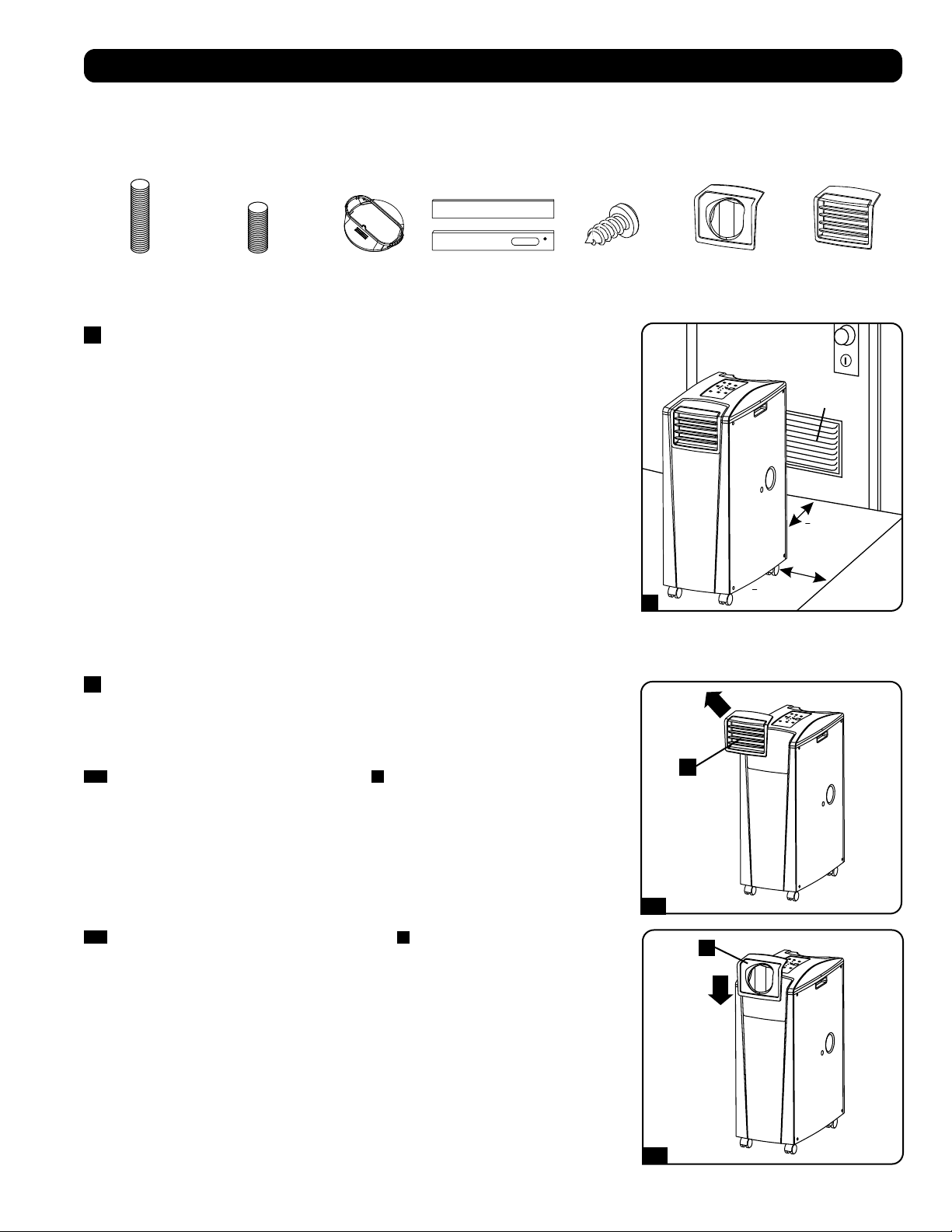
>
51 cm (20 po)
>
51 cm (20 po)
WALL
Évent de
645 cm
2
(100 po.
2
)
(Pour les espaces
confinés)
1
2-1
2-2
A
A
31
Installation
Avertissement : Après avoir retiré l’appareil du conteneur d’expédition, vérifiez la présence de dommages et l’absence de pièces.
(Se reporter à la liste des pièces ci-dessous.) Si vous remarquez un problème, visitez tripplite.com/support pour obtenir du service
après-vente. Ne tentez pas d’utiliser un appareil endommagé.
Liste des pièces accessoires :
1
Disposition de l’appareil
Placez l’appareil sur une surface plate et au niveau près d’une prise c.a. mise à la terre
conforme à la plaque signalétique de l’appareil du point de vue nominal ( 90 à 110 % de la
tension spécifiée). Laissez un espace suffisant autour de l’appareil pour garantir une bonne
circulation d’air, avec l’arrière et les côtés ventilés à au moins 51 cm (20 pouces) des murs et
autres obstacles. Placez l’appareil dans un endroit offrant un accès pratique au faux-plafond
ou à une fenêtre afin d’offrir le cheminement le plus direct et le plus court disponible pour le
conduit d’évacuation flexible. Si vous prévoyez utiliser le conduit de refroidissement flexible afin
de concentrer l’air froid sur une armoire de bâti ou un dispositif spécifique, placez l’unité près
de l’armoire de bâti ou du dispositif visé afin d’offrir le cheminement le plus direct et le plus
court disponible pour le conduit de refroidissement.
Avertissement : Ne pas utiliser de rallonge électrique pour connecter l’appareil à
une prise c.a. Utilisez uniquement la cordon d’alimentation fourni avec l’appareil.
Remarque : Si l’appareil est destiné à être utilisé dans un espace confiné (comme un placard),
vous devez fournir de l’air d’appoint afin de maintenir l’efficacité de la circulation d’air. Un évent
à lames de 645 cm
2
(100 po
2
) ou plus installé près de la partie inférieure de la portière devrait
fournir suffisamment d’air d’appoint pour une armoire typique. Consultez les codes du bâtiment
applicables pour plus d’informations.
Boyau d’évacuation non-illustré – voyez la Section 3
2
Connexion du conduit de refroidissement (en option)
La pièce encastrée de l’évent à lames préinstallé est approprié pour les applications de
refroidissement de la pièce. Si vous prévoyez refroidir une pièce, sautez l’étape 2 et passez à
l’étape 3. Si vous prévoyez utiliser le conduit de refroidissement flexible afin de concentrer l’air
froid sur un dispositif ou une armoire de bâti spécifique, suivez les directives ci-dessous.
2-1
Enlevez la pièce encastrée de l’évent à lames
A
en la tirant vers l’extérieur et vers le haut.
Conduit d’évacuation
(tuyau le plus long)
Conduit de
refroidissement
(tuyau le plus court)
Adaptateur de
conduit d’évacuation
Panneau
d’évacuation
ajustable
(2 sections)
Vis autotaraudeuse 2 Adaptateur
de conduit de
refroidissement
(1 Préinstallé)
Élément encastré
d’évent à lames
(Préinstallé)
2-2
Alignez l’adaptateur du conduit de refroidissement
A
dans l’ouverture de l’évent et le
pousser vers le bas jusqu’à ce qu’il clique en place.
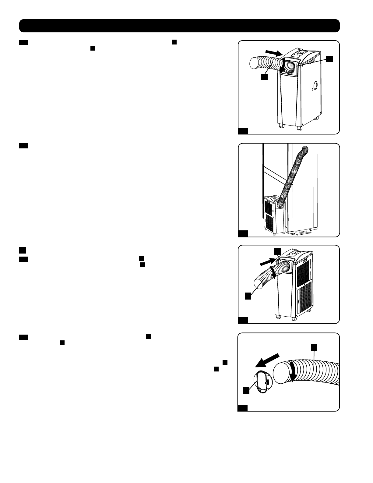
1
2
1
2
1
2
2-3
2-4
3-1
3-2
A
A
B
B
A
B
32
2-3
Connectez le conduit de refroidissement flexible (du tuyau court
A
) à l’adaptateur du
conduit de refroidissement
B
. Alignez le conduit avec l’ouverture circulaire de l’adaptateur,
poussez le conduit vers le haut et tournez le conduit dans le sens des aiguilles d’une
montre jusqu’à ce qu’il soit vissé solidement en place dans l’adaptateur.
Installation
2-4
Placez l’autre extrémité du conduit de refroidissement près de l’admission d’air du
dispositif ou de l’armoire de bâti ciblé(e), en utilisant le cheminement le plus direct et le
plus court disponible. Si vous planifiez de refroidir une armoire de bâti, placez l’extrémité
du conduit de refroidissement sur une surface perforée près de la partie supérieure de la
porte avant de l’armoire (ou près de la partie supérieure du banc de l’équipement devant
être refroidit. L’air froid descendra et se répandra à travers les entrées d’air à l’avant de
l’armoire de bâti.
3
Connexion du conduit d’évacuation
3-1
Connectez le conduit d’évacuation flexible (tuyau
A
le plus long) à l’évent d’évacuation
de l’air chaud sur le panneau arrière de l’appareil
B
. Alignez le conduit avec l’ouverture
circulaire de l’évent, poussez le conduit vers l’intérieur et tournez le conduit dans le sens
des aiguilles d’une montre jusqu’à ce qu’il soit vissé solidement en place dans l’évent
d’évacuation.
3-2
Connectez l’autre extrémité du conduit d’évacuation
A
à l’adaptateur du conduit
d’évacuation
B
. Alignez le conduit avec l’ouverture circulaire de l’adaptateur, poussez
le conduit vers l’intérieur et tournez le conduit dans le sens des aiguilles d’une montre
jusqu’à ce qu’il soit vissé solidement en place dans l’adaptateur.
Si vous prévoyez connecter le conduit d’évacuation à un faux-plafond, passez à l’étape
4
.
Si vous prévoyez connecter le conduit d’évacuation à une fenêtre, passez à l’étape
5
.
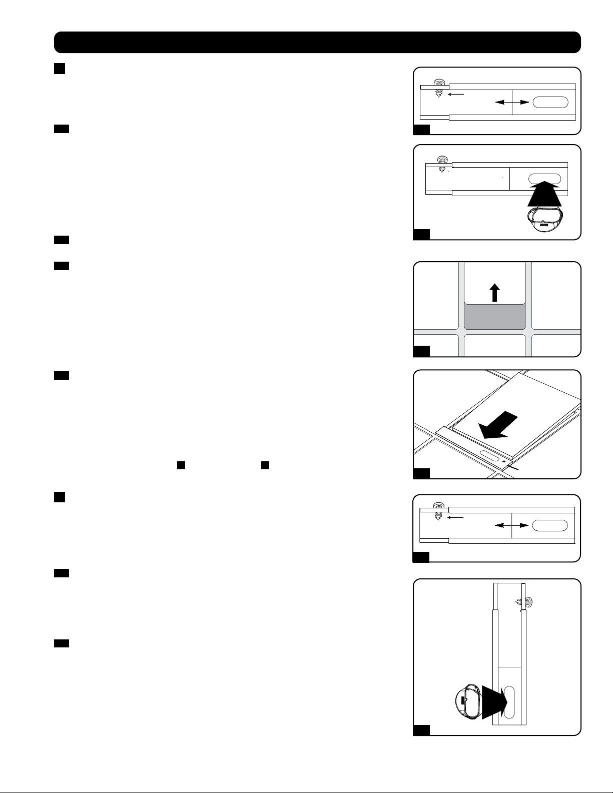
Vis autotaraudeuse
Vis autotaraudeuse
4-1
5-1
4-2
5-2
4-3
4-4
Panneau du plafond
(Vu de dessous)
Panneau de plafond
(Vu de dessus)
Panneau
d’évacuation
33
Installation
4
Connexion de l’évacuation à un faux-plafond
Avertissement : Certains plafonds peuvent exiger des procédures d’installation
modifiées. L’utilisateur doit déterminer la compatibilité de la quincaillerie et
des procédures avant d’effectuer l’installation. Les procédures décrites dans le
présent manuel peuvent ne pas être appropriées pour toutes les applications.
4-1
Choisissez un panneau du faux-plafond à proximité de l’appareil afin d’offrir le
cheminement le plus direct et le plus court disponible pour le conduit d’évacuation flexible.
Mesurez la largeur du panneau de plafond, y compris la portion qui repose sur le support
de plafond. Combinez les deux sections du panneau d’évacuation ajustable, puis ajustez le
panneau d’évacuation afin qu’il corresponde à la largeur du panneau de plafond. Lorsque
le panneau d’évacuation est réglé à la largeur appropriée, utilisez la vis autotaraudeuse
incluse pour le verrouiller en place.
Remarque : Le panneau d’échappement peut être réglé de 52,1 à 104,1 cm (20,5
à 49,2 pouces). Certaines installations peuvent nécessiter de raccourcir le panneau
d’échappement pour une insertion correcte.
4-2
Insérez d’adaptateur de conduit d’évacuation dans le trou oblong dans le panneau
d’évacuation ajustable. L’adaptateur cliquera en place.
4-3
Glissez le panneau de plafond et mettre de côté et placez le panneau d’évacuation à
l’intérieur de l’espace du plafond. Permettre au panneau d’évacuation de reposer sur le
support de plafond.
Remarque : Il doit y avoir un espace d’au moins 25,4 cm (10 pouces) au-dessus du
panneau de plafond pour permettre une circulation d’air appropriée.
4-4
Glissez le panneau de plafond pour le remettre en place de façon à ce qu’il soit contigu
au panneau d’évacuation et qu’il couvre les écarts du plafond. Une bonne étanchéité
permettra une efficacité de refroidissement maximale. Si l’installation est permanente,
tailler le panneau de plafond afin qu’il ne chevauche pas le support de plafond.
Remarque : Le conduit d’évacuation flexible peut être prolongé jusqu’à une longueur
maximum de 300 cm (118 pouces). Veillez à fournir le cheminement le plus direct et le
plus court possible. Toute flexion ou allongement excessif(ve) du conduit aura pour effet
de réduire l’efficacité de refroidissement.
Après avoir complété l’étape
4
, passez à l’étape
6
.
5
Window Exhaust Connection
Connexion de l’évacuation à une fenêtre
Avertissement : Certaines fenêtres peuvent exiger des procédures d’installation
modifiées. L’utilisateur doit déterminer la compatibilité de la quincaillerie et
des procédures avant d’effectuer l’installation. Les procédures décrites dans le
présent manuel peuvent ne pas être appropriées pour toutes les applications.
5-1
Mesurez l’ouverture de la fenêtre. Combinez les deux sections du panneau d’évacuation
ajustable, puis ajustez le panneau d’évacuation afin qu’il corresponde à la largeur
de l’ouverture de la fenêtre. Lorsque le panneau d’évacuation est réglé à la largeur
appropriée, utilisez la vis autotaraudeuse incluse pour le verrouiller en place.
Remarque : Le panneau d’évacuation peut être ajusté de 52,1 à 104,1 cm (20,5 à 49,2
pouces). Il est compatible avec un montage vertical et un montage horizontal.
5-2
Insérez l’adaptateur du conduit d’évacuation dans le trou oblong dans le panneau
d’évacuation ajustable. L’adaptateur cliquera en place.
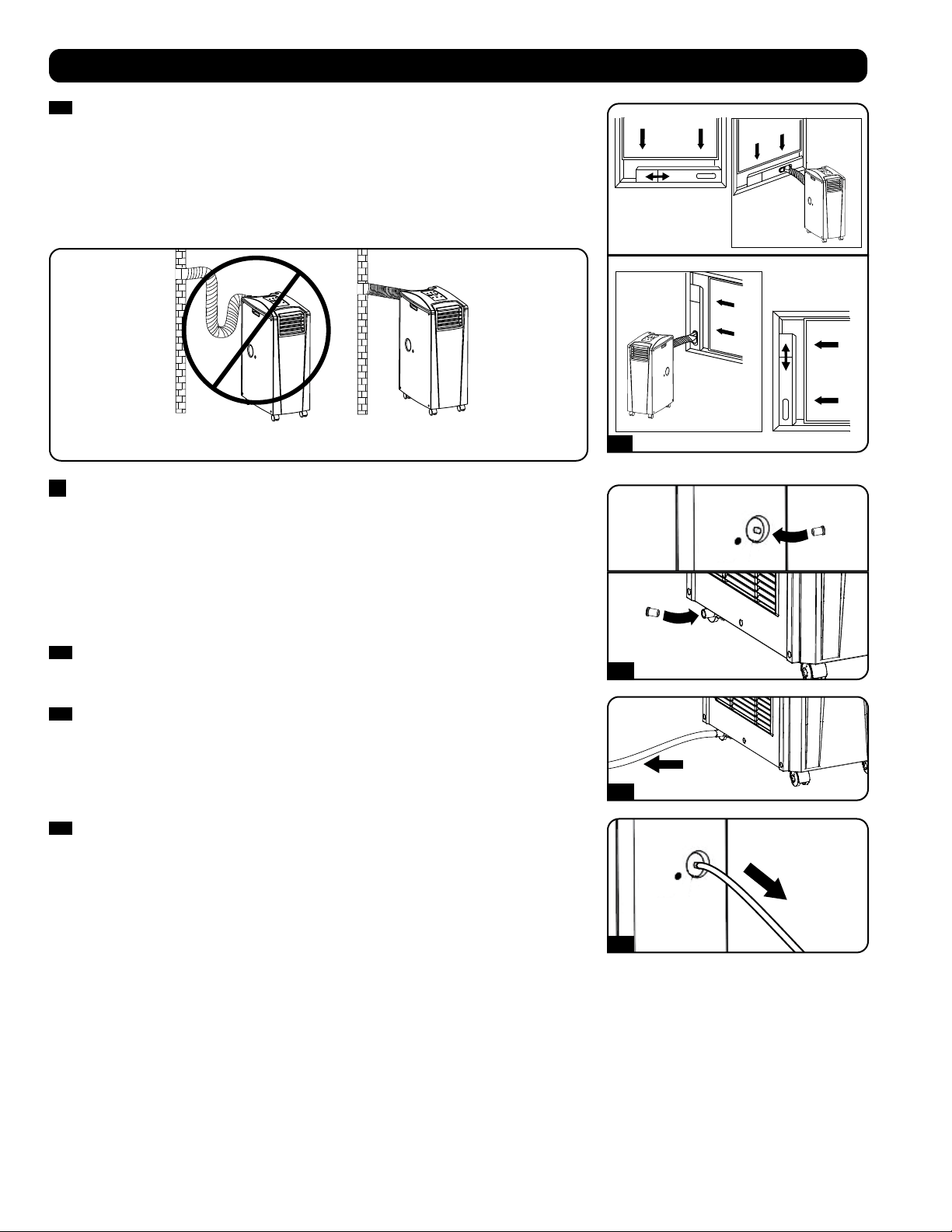
Ouverture de
fenêtre
verticale
Ouverture
de fenêtre
verticale
INCORRECT CORRECT
5-3
6-1
6-2
6-3
POUR VIDER
POUR VIDER
34
Installation
5-3
Insérez le panneau d’évacuation dans l’ouverture de la fenêtre, puis fermez la fenêtre
contre le panneau d’évacuation. Une bonne étanchéité permettra une efficacité de
refroidissement maximale. Remarque : Il doit y avoir un espace d’au moins 25,4 cm (10
pouces) derrière le panneau de plafond pour permettre une circulation d’air appropriée.
Remarque : Le conduit d’évacuation flexible peut être prolongé jusqu’à une longueur
maximum de 300 cm (118 pouces). Veillez à fournir le cheminement le plu direct et le
plus court possible. Toute flexion ou allongement excessif(ve) du conduit aura pour effet
de réduire l’efficacité de refroidissement.
6
Insertion du bouchon d’évacuation
Avertissement : Le dispositif intégré à l’appareil et servant à faire réévaporer ne
fonctionnera pas tant que vous n’aurez pas insérer le bouchon de drainage dans la
sortie de drainage.
Lorsque l’appareil refroidit ou déshumidifie, il se forme de la condensation. L’appareil est
équipé d’un dispositif de réévaporation qui lui permet d’expulser la condensation par le flux
d’évacuation de l’air chaud. Cette fonction permet à l’appareil de fonctionner indéfiniment sans
que vous ayez à vider le réservoir de récupération d’eau. L’appareil est expédié alors que les
deux bouchons de drainage supérieur et inférieur sont en place.
6-1
Mode de refroidissement avec évaporation
Les deux bouchons doivent demeurer en place pour permettre l’évaporation normale de la
condensation.
6-2
Mode de refroidissement sans évaporation
Pour utiliser le mode de refroidissement sans évaporation de la condensation, retirez le
bouchon de la sortie de drainage inférieure et acheminez le tuyau de drainage fourni par
l’utilisateur vers le drainage extérieur. Le bouchon de la sortie de drainage supérieure doit
demeurer en place.
6-3
Mode de déshumidification
Lorsque vous utilisez l’appareil dans le mode de déshumidification, retirez le bouchon de
la sortie de drainage supérieure et acheminez le tuyau de drainage fourni par l’utilisateur
vers le drainage extérieur. Le bouchon de la sortie de drainage inférieure doit demeurer en
place. Ceci maximisera le montant d’eau extraite de l’air.
Remarque : Si le système de drainage venait qu’à se boucher, un petit réservoir interne
recueillera la condensation. Si le système de drainage n’est pas débouché avant que le
réservoir interne soit rempli, l’appareil s’arrêtera automatiquement.
Avertissement : Mettre l’appareil hors tension et le débrancher avant de le
connecter à un système d’évacuation réservé à cet effet. Il y a un risque de
choc électrique lorsque l’appareil est branché.
Fonctionnement à basse température
Le climatiseur est un refroidisseur à haut rendement ayant la capacité de produire de l’air très froid à la sortie. Lorsque l’appareil est utilisé dans
des environnements qui sont déjà froids (20 °C/68 °F ou moins), Tripp Lite recommande d’utiliser le « DEHUMIDIFY MODE » (mode déshumidifier)
seulement. Cela permettra à l’appareil de continuer à fournir un refroidissement complémentaire tout en évitant tout problème de givrage au
niveau de l’évaporateur causé par la basse température de la pièce.
Remarque : Si le système de refroidissement de votre établissement est équipé d’un thermostat qui abaisse la température pour la nuit
ou les fins de semaine, fait l’objet d’arrêts périodiques ou a une capacité de refroidissement limitée, vous devriez peut-être envisager des
alternatives à l’installation standard. Ce produit est destiné à servir de dispositif de refroidissement complémentaire et ne saurait compenser
les fluctuations importantes au niveau de la température et de l’humidité du bâtiment.
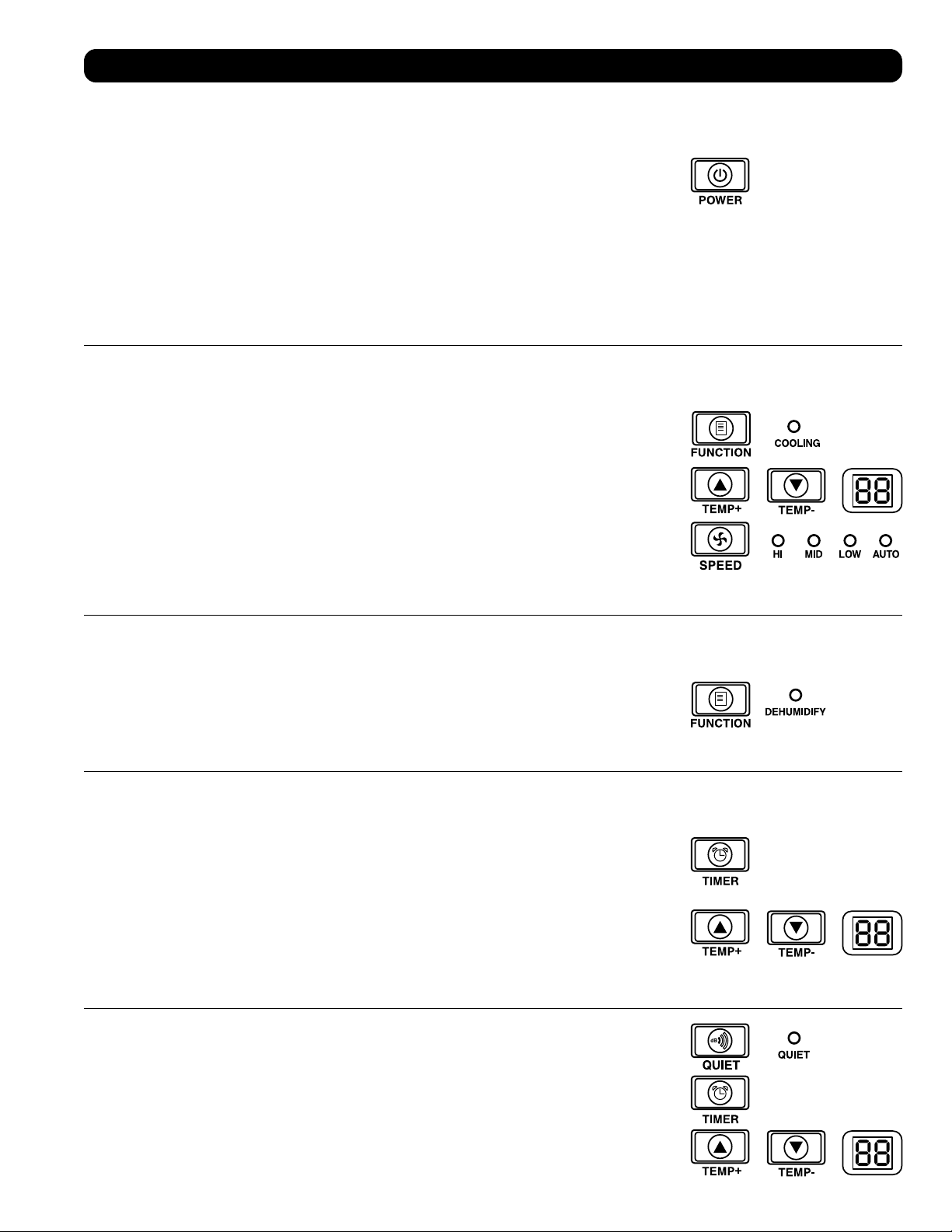
35
Fonctionnement
Avertissement : Installez l’appareil conformément aux directives de la section « Installation » afin de tenter de la faire
fonctionner.
Alimentation
Activez ou désactivez l’appareil en pressant le bouton « POWER » (ALIMENTATION).
L’appareil est équipé d’un circuit qui retarde l’activation du compresseur de trois (3) minutes pour éviter
les surcharges potentielles du circuit au démarrage.
Fonction de redémarrage automatique
L’appareil s’activera automatiquement et continuera à fonctionner lorsque l’alimentation est restaurée
suite à une rupture de courant. L’appareil utilisera les mêmes réglages qui étaient en fonction
immédiatement avant que survienne la rupture de courant. Remarque : Si la rupture de courant
est brève, l’appareil activera uniquement le ventilateur pendant trois (3) minutes avant de passer au
fonctionnement normal. La temporisation permet au compresseur de se dépressuriser pour que l’appareil
fonctionne correctement lorsqu’il est commuté au mode « Cool » (Climatisation).
Mode Climatisation
La pression du bouton « FUNCTION » (FONCTION) alterne entre le mode « Cool » (Climatisation) et le mode
« Dehumidify » (Déshumidification). Le voyant DEL « COOLING » (CLIMATISATION) s’allume lorsque la mode
« Cool » (Climatisation) est actif.
Pressez les boutons « TEMP+ » et « TEMP- » pour régler la température dans le mode “Cool”
(Climatisation). La température sélectionnée est affichée à l’écran numérique. Une fois la température
voulue réglée, son affichage clignotera cinq fois après quoi la température ambiante de l a salle sera
affichée.
Pressez le bouton « FAN SPEED » (VITESSE DU VENTILATEUR) pour choisir entre les vitesses haute,
moyenne et basse du ventilateur. Un voyant DEL s’allume pour indiquer la vitesse sélectionnée du
ventilateur. Lorsque la vitesse est réglée à « AUTO », l’appareil sélectionnera automatiquement la vitesse
du ventilateur en fonction de la température réglée et de la température ambiante. Si la température
ambiante est plus basse que la température choisie, le ventilateur fonctionnera et la DEL « COOLING »
(REFROIDISSEMENT) clignotera pour indiquer que le compresseur est arrêté. Lorsque la fonction de
refroidissement est rétablie, la DEL « COOLING » (REFROIDISSEMENT) demeurera allumée.
Déshumidification
La pression du bouton « FUNCTION » (FONCTION) alterne entre le mode « Cool » (Climatisation) et le mode
« Dehumidify » (Déshumidification).
Le voyant DEL « DEHUMIDIFY » (DÉSHUMIDIFICATION) s’allume lorsque ce mode est actif. Dans le mode
de déshumidification, le ventilateur fonctionne à une vitesse fixe et les contrôles de la température sont
sans objet. Pour une performance maximale dans le mode de déshumidification, fermez les fenêtres et
les portes, retirez le bouchon de la sortie de drainage supérieure et acheminez le tuyau de drainage fourni
par l’utilisateur vers le drainage extérieur.
Minuterie
Le bouton « TIMER » (MINUTERIE) vous permet de configurer l’appareil pour qu’il s’active et se désactive
automatiquement.
« Timer On » (Minuterie active) [Remarque : L’appareil doit être arrêté pour activer la fonction « Timer
On » (Minuterie active).] Activez la minuterie en pressant le bouton « TIMER » (MINUTERIE). Pressez les
boutons « TEMP+ » et « TEMP- » pour régler la durée de temps (en heures) avant que l’unité se mette en
marche. Le nombre d’heures est affiché à l’écran numérique. Le nombre clignotera cinq (5) fois à l’écran
avant de retourner à la température courante.
« Timer Off » (Minuterie inactive) [Remarque : L’appareil doit être en marche pour activer la fonction
« Timer Off » (Minuterie inactive).] Activer la minuterie en pressant le bouton « TIMER » (MINUTERIE).
Pressez les boutons « TEMP+ » et « TEMP- » pour régler la durée de temps (en heures) avant que l’unité
s’arrête. Le nombre d’heures est affiché à l’écran numérique. Le nombre clignotera cinq (5) fois à l’écran
avant de retourner à la température courante.
Mode Silencieux
L’appareil est équipé d’un mode Silencieux où la climatisation est contrôlée par la minuterie et le
microprocesseur pour assurer un niveau plus silencieux de fonctionnement lorsque que le bruit est un
problème.
Pour activer, pressez le bouton « Quiet » (SILENCIEUX). Le voyant DEL « Quiet » (Silencieux) s’allumera.
Réglez la température désirée et réglez la minuterie à la durée du cycle du mode de contrôle « Quiet
» (Silencieux). Au long du cycle, la mémoire du microprocesseur abaissera, à toutes les trente (30)
minutes, la température de 0,5° C (0,9° F) jusqu’à ce que la température réglée soit atteinte. Lorsque
cette température est atteinte, l’appareil la maintiendra pour la durée de temps réglée.
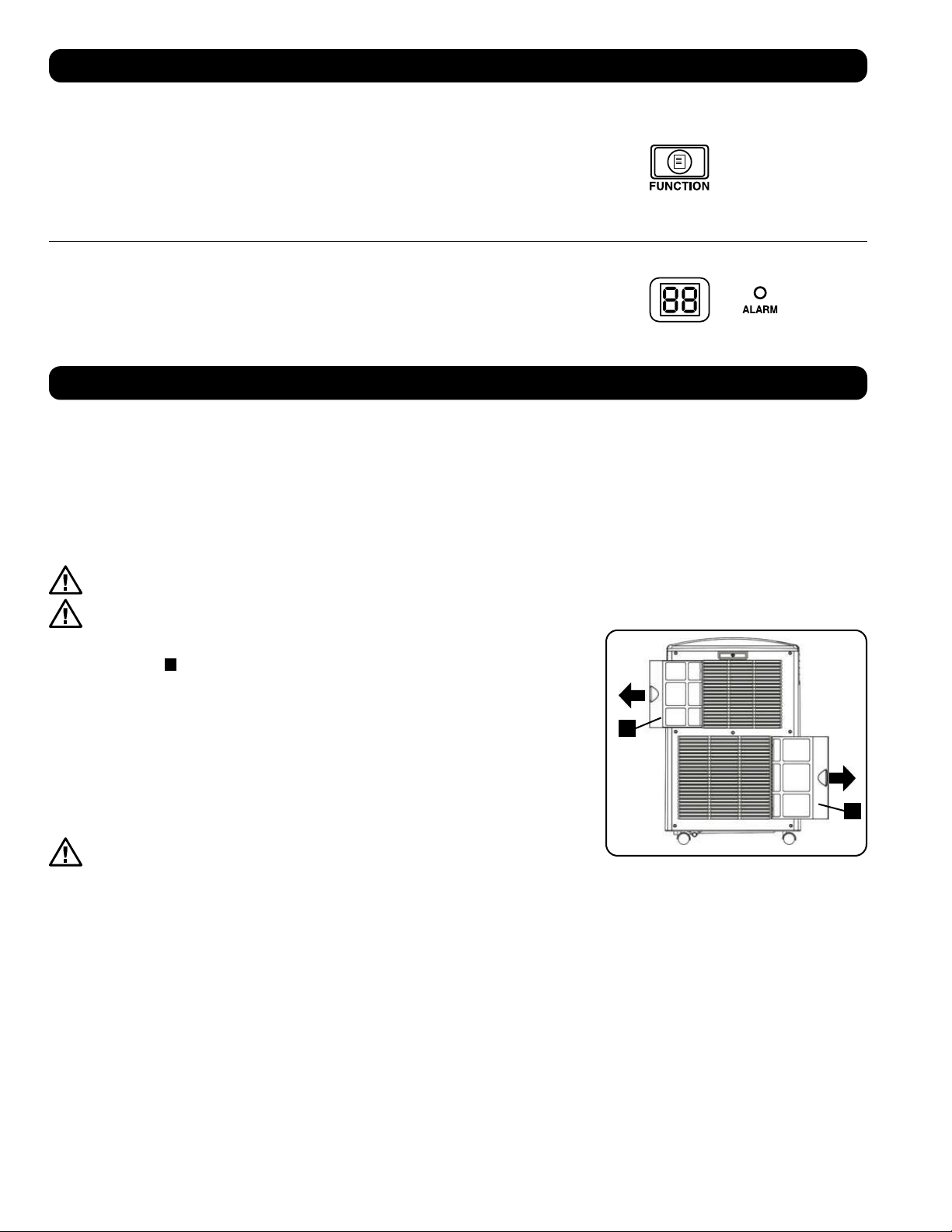
A
A
36
Fonctionnement
Nettoyage et maintenance
Nettoyer le climatiseur, puis nettoyer ou remplacer régulièrement les filtres pour maximiser le rendement et l’efficacité, prolonger la durée de vie
utile de l’appareil et avoir droit à la garantie en cas de problème de rendement.
Remarque : Toujours débrancher le climatiseur de la prise de courant avant le nettoyage.
Nettoyage des filtres à air
Il est important de garder les filtres à air propres et exempts de poussière. Lorsque les filtres sont sales ou obstrués par de la poussière, cela
a pour effet de diminuer l’efficacité du refroidissement et risque de menacer la qualité de l’air. Tripp Lite recommande de nettoyer les filtres au
moins une fois par deux semaines. Si l’appareil est utilisé dans un environnement poussiéreux, les filtres devront peut-être être nettoyés ou
remplacés chaque semaine.
Avant de nettoyer les filtres, mettre l’appareil hors tension et le débrancher! Il y a un risque de choc électrique lorsque
l’appareil est branché.
Ne faites jamais fonctionner le climatiseur sans le filter.
1. Mettre l’appareil hors tension et le débrancher.
2. Enlevez les filtres
A
en les faisant glisser hors de l’armoire.
3. Utiliser un aspirateur ou taper légèrement sur le filtre pour déloger la poussière et les saletés.
4. Lavez les filtres à l’eau tiède avec un détergent neutre. Ne pas mettre les filtres dans un
lave-vaisselle ou utiliser des détergents ou des produits chimiques corrosifs. Laissez sécher
les filtres complètement à l’air libre après le nettoyage.
Remarque : Ne pas utiliser de l’eau dont la température excède 40° C (104° F) pour laver les filtres.
5. Replacez les filtres en les faisant glisser dans leur position originale.
6. Brancher l’appareil et reprendre les activités normales.
Nettoyage de l’armoire
Avant de nettoyer l’armoire, mettre l’appareil hors tension et le débrancher!
Il y a un risque de choc électrique lorsque l’appareil est branché.
1. Mettre l’appareil hors tension et le débrancher.
2. Utiliser un chiffon sec non abrasif pour essuyer l’armoire. Au besoin, utiliser de l’eau tiède pour humidifier le chiffon. Ne jamais utiliser
des produits chimiques abrasifs, des substances volatiles, du carburant, du benzène, des diluants, des détergents, des chiffons traités
chimiquement ou d’autres produits chimiques puissants ou des solvants de nettoyage qui pourraient endommager l’extérieur de l’armoire.
Ne pas verser de l’eau directement sur l’appareil ou sur les pièces mobiles. Cela présenterait un risque de décharge électrique et risquerait de
détériorer les composants électriques et l’isolation des câbles.
3. Utiliser une brosse à poils souples pour nettoyer entre les évents.
4. Utiliser délicatement un aspirateur pour nettoyer les serpentins du condensateur.
Changement des unités de température
L’appareil SRCOOL12K peut afficher la température en unités Celsius ou en unités Fahrenheit.
Le réglage par défaut pour la SRCOOL12K est en Fahrenheit et la SRXCOOL12K/SRXCOOL12KA/
SRXCOOL12KB est Celsius.
Pour alterner entre les unités, commutez le SRCOOL12K au mode d’attente. Le climatiseur se trouve
dans le mode d’attente lorsqu’il est branché à une prise de courant sous tension, alors que l’appareil
est commuté hors tension. Maintenir ensuite la touche « FUNCTION » (fonction) enfoncée pendant 10
secondes. Pour vérifier que l’unité pour les degrés a été changée, mettre l’appareil sous tension.
Alarme
Lorsque le réservoir d’eau est plein, l’appareil affichera le message « E4 » à l’écran. Pour retourner
à un fonctionnement normal, commuter l’appareil hors tension, retirez le bouchon de drainage pour
évacuer l’excès d’eau de l’appareil. Remettez le bouchon et commutez l’appareil sous tension pour
activer la climatisation.
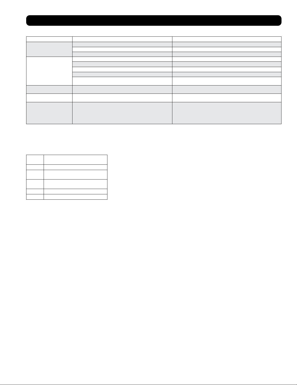
Code dF
« dF » s’affichera si le dispositif SRCOOL12K/SRXCOOL12K/SRXCOOL12KA/SRXCOOL12KB détecte un problème lié au fonctionnement de la
bobine à moins de 1 °C (33,8 °F) pendant plus de 15 minutes.
En cas de code dF affiché, les ventilateurs de l’appareil fonctionneront sans le compresseur pour éviter le gel de l’évaporateur. Une fois la
température revenue au-dessus de 1 °C (33,8 °F), le compresseur reprendra son fonctionnement normal.
Si le problème persiste, l’appareil fonctionne dans un environnement trop froid. Tripp Lite recommande de faire fonctionner l’appareil en mode
de déshumidification uniquement si la température de fonctionnement est inférieure à 20 °C (68 °F). Référez-vous au fonctionnement à basse
température de la section 6-3 pour plus d’informations.
37
Codes d’affichage supplémentaires
Codes d’erreur
Le SRCOOL12K/SRXCOOL12K/SRXCOOL12KA/SRXCOOL12KB de Tripp Lite a la possibilité de se surveiller continuellement. En cas d’erreur,
l’affichage indiquera un des 5 codes d’erreur suivants :
Code
d’erreur Description
E0 Erreur de communication interne
E1 Erreur au niveau de la sonde de
température intérieure
E2 Erreur au niveau de la sonde de
température interne
E3 Erreur au niveau du réfrigérant
E4 Réservoir d’eau plein
Le code E4 peut être effacé en vidant le réservoir d’eau. Consulter l’entrée Alarme dans la
section Fonctionnement pour plus de détails.
Pour les codes E0, E1, E2 et E3, suivre les étapes suivantes :
1. Mettre l’appareil hors tension en le débranchant de la source d’alimentation pendant 5
minutes; puis le mettre sous tension à la fin de cette période.
2. Rebrancher l’appareil.
3. Redémarrer l’appareil.
Si le code est effacé, continuer de faire fonctionner l’appareil de façon normale. Si le code
s’affiche de nouveau, veuillez contacter Tripp Lite pour obtenir d’autres instructions.
Dépannage
Passez en revue les solutions possible ci-dessous. Si le problème persiste, visitez tripplite.com/support pour obtenir du service après-vente.
Problème Cause possible Solution possible
L'appareil ne fonctionne pas. L'appareil est hors tension. Mettre l'appareil sous tension. (Consultez la section « Fonctionnement ».)
L'appareil n'est pas branché. Brancher l'appareil dans une prise appropriée.
L'alimentation principal est hors tension. Vérifier les fusibles ou le disjoncteur.
Le rendement du système
de refroidissement n'est pas
satisfaisant.
L'entrée ou la sortie d'air est obstruée. Confirmer que tous les conduits et les entrées sont libres de débris.
Le réglage de la température est trop élevé. Adjuster le réglage de la température.
Le réglage de la vitesse du ventilateur est trop faible. Adjuster le réglage du ventilateur.
Les filtres à air sont sales. Nettoyer les filtres à air.
La puissance de l'armoire de bâti, la grandeur de la pièce ou la température
ambiante excède la capacité de refroidissement d'un seul appareil.
Installez des appareils additionnels ou contacter Tripp Lite pour des solutions de
refroidissement additionnelles appropriées pour votre application.
Fuite d'eau au niveau de l'appareil. Le bouchon de drainage n'est pas installé. Insérer le bouchon de drainage dans la sortie de drainage.
(Consultez la section « Installation ».)
L'appareil produit beaucoup de
bruit ou de vibration.
L'appareil se trouve sur une surface inégale ou instable. Déplacer l'appareil sur une surface au niveau et stable.
L’appareil présente une
accumulation de glace ou de givre.
L’appareil est utilisé dans un environnement où l’humidité est excessive. OPTION 1 : Mettre l’appareil hors tension et lui permettre de dégivrer. Une fois
l’appareil dégivré, s’assurer qu’il fonctionne lorsque la vitesse du ventilateur est réglée
à HIGH (élevée).
OPTION 2 : Mettre l’appareil hors tension et lui permettre de dégivrer. Une fois
l’appareil dégivré, le faire fonctionner en DEHUMIDIFY MODE (mode déshumidifier) ou
élever le point de consigne de la température désirée.
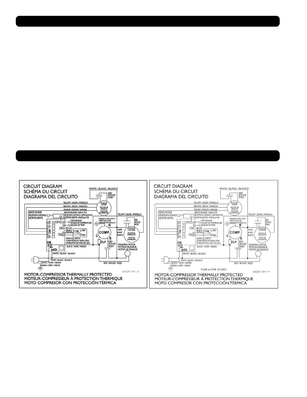
38
Entreposage et service
Entreposage
Avant d’entreposer l’appareil, s’assurer que les conduits et les évents sont bien retenus en place ou enlevés et rangés convenablement.
S’assurer également que l’appareil a été drainé de toute condensation.
Service
Cette armoire est couverte par la garantie limitée décrite dans ce manuel. Une gamme de programmes de garantie prolongée et de service sur
place sont également offerts par Tripp Lite. Pour plus de renseignements sur ce service, visitez tripplite.com/support. Avant de retourner votre
produit pour service, suivez les étapes suivantes :
1. Passer en revue les procédures d’installation et d’opération de ce manuel afin de vous assurer que le problème en question ne provient pas
d’une fausse interprétation des instructions.
2. Si le problème persiste, ne pas contacter ou retourner le produit au détaillant. Visitez plutôt tripplite.com/support.
3. Si le problème nécessite des réparations, visitez tripplite.com/support et cliquez sur le lien Product Returns (Retour des produits). De là, vous
pouvez demander un numéro de retour de matériel (RMA) qui est requis pour une réparation. Ce formulaire simple en ligne vous demandera le
modèle de l’unité et le numéro de série ainsi que d’autres renseignements généraux sur l’acheteur. Le numéro RMA ainsi que les instructions
relatives à l’expédition vous seront envoyés par courriel. Tout dommage (direct, indirect, spécial ou consécutif) que le produit pourrait subir
durant la livraison vers Tripp Lite ou un centre de réparation reconnu par Tripp Lite n’est pas couvert sous cette garantie. Les produits envoyés
à Tripp Lite ou un centre de réparation reconnu par Tripp Lite doivent être envoyés en port prépayé. Inscrire le numéro RMA à l’extérieur de
l’emballage. Si le produit est encore à l’intérieur de la période de garantie, veuillez inclure une copie de votre reçu. Retourner le produit pour
réparation en utilisant un transporteur assuré à l’adresse qui vous sera donnée lors de votre demande de RMA.
Schémas des circuits
Les schémas suivants sont donnés à titre indicatif seulement. Il n’existe aucune pièce réparable par l’utilisateur à l’intérieur de l’appareil.
Schéma du circuit, SRCOOL12K Schéma du circuit, SRXCOOL12K, SRXCOOL12KA, SRXCOOL12KB
1111 W. 35th Street, Chicago, IL 60609 USA • tripplite.com/support
20-03-239 93-33FA_RevE
39
Garantie
GARANTIE LIMITÉE DE 2 ANS (États-Unis et Canada)
GARANTIE LIMITÉE DE 1 AN (toutes les autres régions)
Le vendeur garantit que ce produit, s’il est utilisé conformément à toutes les instructions applicables, est exempt de tous défauts de matériaux et de fabrication pour une période de 2 ans (sauf aux États-
Unis et au Canada) ou 1 an (toutes les autres régions) à partir de la date d’achat initiale. Si le produit s’avère défectueux en raison d’un vice de matière ou de fabrication au cours de cette période, le
vendeur s’engage à réparer ou remplacer le produit, à sa seule discrétion. Le service sous cette garantie ne peut être obtenu qu’en livrant ou en expédiant le produit (avec tous les frais d’expédition ou de
livraison prépayés) à : Tripp Lite, 1111 W. 35th Street, Chicago, IL 60609 USA. Le vendeur paiera les frais d’expédition de retour.
Les limitations suivantes s’appliquent à la couverture de cette garantie. Cette garantie ne couvre pas :
• Les frais de main-d’œuvre pour l’installation, la configuration ou la formation pour l’utilisation du produit
• Les dommages survenant au cours de l’expédition ou tout dommage causé par un emballage inapproprié pour l’expédition à un centre de réparation autorisé et tout dommage causé par une mauvaise
tension ou autre utilisation abusive, y compris un service, une manutention ou un usage anormal
• Les dommages esthétiques comme les égratignures et les bosses
• L’usure normale sur les pièces ou les pièces de remplacement conçues pour être remplacées, p. ex. les filtres, les cartouches, les batteries
• Les déplacements pour la livraison, la récupération ou la réparation, l’installation du produit ou pour montrer comment se servir du produit
• Les dommages ou les problèmes de fonctionnement résultant d’une mauvaise utilisation, d’un abus, d’un fonctionnement en dehors des caractéristiques environnementales, de l’usage contraire aux
directives fournies dans le manuel de l’utilisateur, des accidents, des catastrophes naturelles, de la vermine, d’un incendie, d’une inondation, d’une mauvaise utilisation, d’un entretien non autorisé,
d’une négligence lors de l’entretien, d’une installation, d’une modification ou d’une location non autorisée ou d’une utilisation commerciale
• L’utilisation du produit dans des lieux commerciaux ou de location
• Accessoires en option et des éléments décoratifs
• Les produits qui ont été modifiés pour fonctionner en dehors des caractéristiques techniques
• Les produits dont le numéro de série a été éliminé ou dégradé
• Les produits dont le numéro de série a été invalidé
• Les dommages aux biens personnels dus à l’utilisation du produit
• Le remplacement ou la réparation des fusibles, des disjoncteurs, du câblage ou de la plomberie de l’installation
Garantie
Conformité aux règlements
Numéros d’identification de conformité aux règlements
À des fins de certification et d’identification de conformité aux règlements, votre produit Tripp Lite a reçu un numéro de série unique. Ce numéro de série se trouve sur la plaque signalétique du produit, avec
toutes les inscriptions et les informations d’approbations requises. Lors d’une demande d’information de conformité, pour ce produit, utiliser toujours le numéro de série. Le numéro de série ne doit pas être
confondu avec le nom de la marque ou le numéro de modèle du produit.
L’information de conformité WEEE pour les clients de Tripp Lite et recycleurs (Union européenne)
Remarque : Cette déclaration s’applique aux produits portant le logo WEEE.
Sous les directives et règlements de déchet d’équipements électrique et électronique (Waste Electrical and Electronic Equipment, WEEE), lorsque les clients achètent le matériel électrique et
électronique neuf de Tripp Lite ils sont autorisés à :
• Envoyer le vieux matériel pour le recyclage sur une base de un-contre-un et en nature (ceci varie selon le pays).
• Renvoyer le matériel neuf pour recyclage quand ceci devient éventuellement un rebut.
Il est déconseillé d’utiliser cet équipement dans des applications médicales où une panne de cet équipement pourrait normalement provoquer la panne de l’équipement de survie ou altérer notablement sa
sécurité ou son efficacité.
Tripp Lite applique une politique d’amélioration continue. Les spécifications peuvent être modifiées sans préavis.
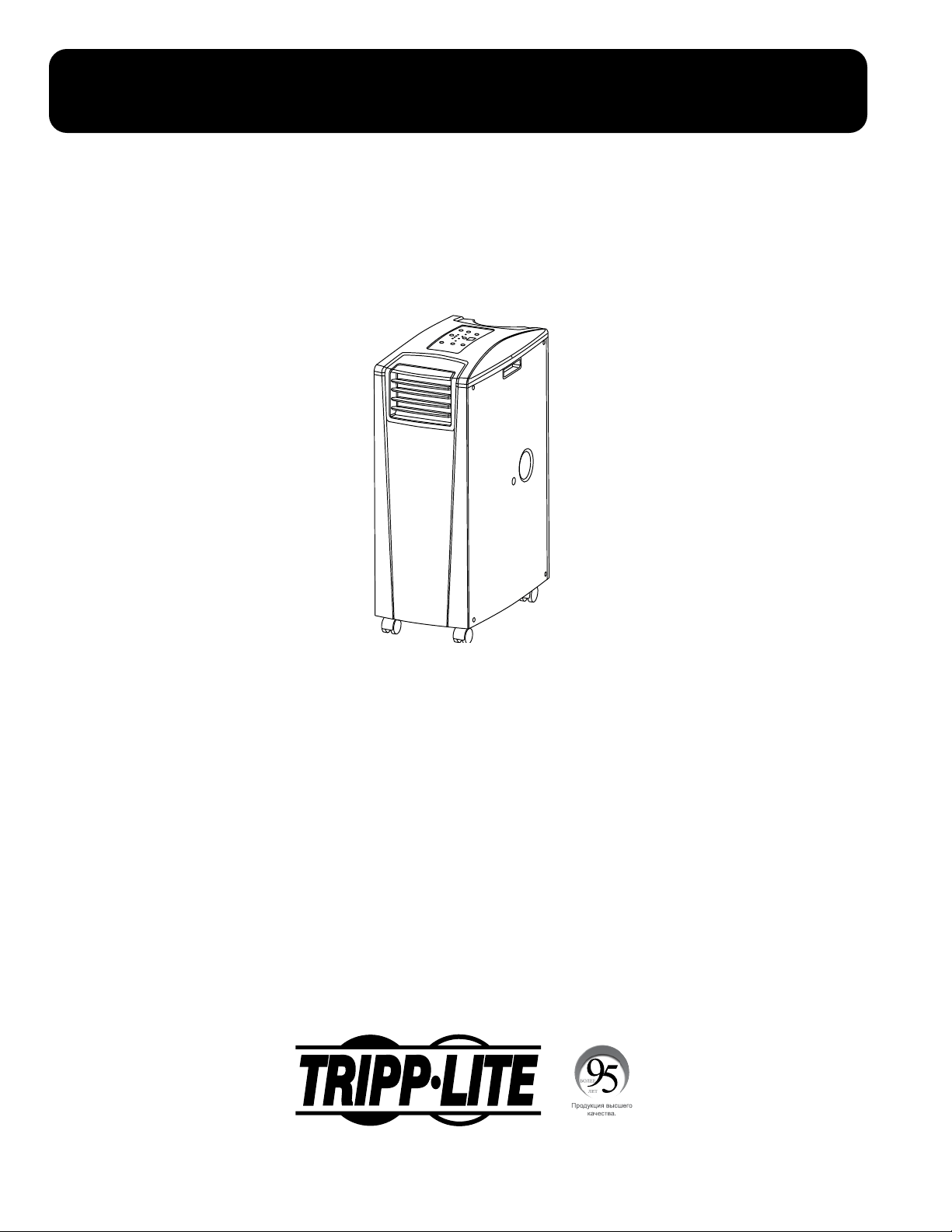
40
Переносной блок кондиционирования
SRCOOL12K – Серийный номер: AG-0073 (120 В , 60 Гц)
SRXCOOL12K – Серийный номер: AG-00A0 (230 В , 50 Гц)
SRXCOOL12KA – Серийный номер: AG-0533 (230 В , 50 Гц)
SRXCOOL12KB – Серийный номер: AG-00A0 (230 В , 50 Гц)
Руководство пользователя
Введение 41
Важные правила техники безопасности 41
Детали и элементы 43
Установка 44
Эксплуатация 48
Очистка и Техническое обслуживание 49
Выявление и устранение неисправностей
50
Хранение и обслуживание 51
Принципиальная электрическая схема 51
Гарантийные обязательства 52
нормативным требованиям 52
English 1
Español 14
Français 27
1111 W. 35th Street, Chicago, IL 60609 USA • tripplite.com/support
Охраняется авторским правом © 2020 Tripp Lite. Перепечатка запрещается.
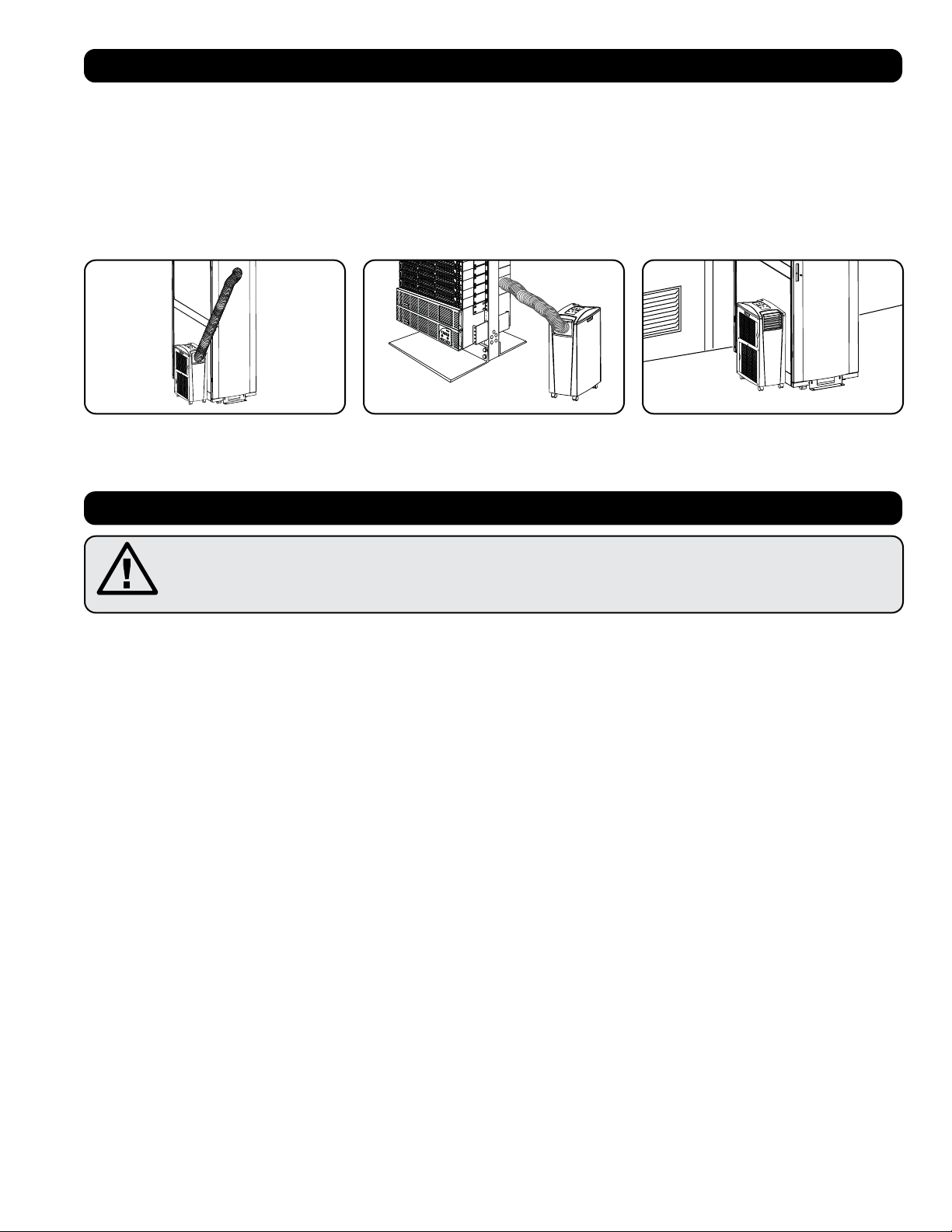
SYST
RPS
STAT
DUPLX
SPEED
MODE
1
5
X
3
1
X
3
3
X
4
7
X
5
0
MASTR
STACK
SYST
RPS
STAT
DUPLX
SPEED
MODE
1
5
X
3
1
X
3
3
X
MASTR
STACK
SYST
RPS
STAT
DUPLX
SPEED
MODE
1
5
X
3
1
X
3
3
X
MASTR
STACK
MODE
1
5
X
3
1
X
3
3
X
STACK
4
7
X
5
0
4
7
X
5
0
4
7
X
5
0
4
7
X
5
0
5
0
41
Введение
Автономное переносное устройство кондиционирования воздуха обеспечивает дополнительную холодопроизводительность в размере 12 000 BTU
(до 3,4 кВт). Это устройство, предназначенное для работы в ИТ-средах, идеально подходит для охлаждения перегревающихся корпусных стоек, мест
плотного размещения ИТ-оборудования и сетевых узлов, расположенных вне зоны действия системы центрального кондиционирования объекта. Этот
переносной кондиционер способен проводить концентрированные потоки холодного воздуха через свой гибкий канал охлаждения или охлаждать
небольшое помещение, направляя холодный воздух через свое выходное отверстие с жалюзийными заслонками. Кроме того, он обеспечивает
фильтрацию и осушение воздуха, что способствует улучшению условий работы оборудования и повышению его надежности. Образующийся конденсат
повторно испаряется, что исключает возможность подтекания и позволяет не тратить время на опорожнение емкостей для сбора воды. Автономная
конструкция не требует подключения к водопроводу, канализации или специальным сетям, что ускоряет и облегчает процесс начальной установки.
Экологически чистый хладагент R410A соответствует требованиям международных природоохранных стандартов.
Рекомендуемые цели применения:
Важные указания по технике безопасности
СОХРАНИТЕ НАСТОЯЩИЕ УКАЗАНИЯ
В настоящем руководстве содержатся указания и предупреждения, которые необходимо соблюдать в процессе
установки, эксплуатации и хранения данного изделия. Игнорирование этих предупреждений может привести к
потере вашей гарантии.
Предупреждения
• Перед началом использования данного устройства пользователь должен убедиться в том, что оно является пригодным, соответствующим или
безопасным для предполагаемого применения. В связи с большим разнообразием конкретных применений производитель не дает каких-либо
заверений или гарантий относительно пригодности данного изделия для какого-либо конкретного применения или его соответствия каким-либо
конкретным требованиям.
• Данное устройство должно быть установлено в закрытом помещении и защищено от воздействия экстремальных температур и влажности, а также
попадания прямого солнечного света, пыли и электропроводных загрязнителей.
• Вокруг устройства должно быть обеспечено достаточное пространство для вентиляции, а его задняя стенка и вентиляционные отверстия должны
находиться на расстоянии не менее 51 см от стен или других препятствий.
• Устройство должно быть установлено на ровной поверхности с уклоном не более 10°.
• Подключайте устройство непосредственно к заземленной розетке сети переменного тока. Несоблюдение этого требования может привести к
поражению электрическим током или возгоранию.
• Данное устройство предназначено для вспомогательного охлаждения участков локального перегрева.
• Номинальные параметры электропитания данного устройства должны соответствовать указанным на его заводской табличке.
• Не переделывайте электрическую вилку и не используйте переходник, не поддерживающий заземления.
• Не используйте шнур-удлинитель для подключения устройства к розетке сети переменного тока. Используйте только шнур питания, поставляемый
в комплекте с устройством.
• Соблюдайте все действующие нормы и правила электромонтажа и техники безопасности, такие как Национальный свод законов и стандартов США
по электротехнике (NEC).
• Не подключайте дополнительное оборудование к розетке, в которую включено данное устройство. Перегрузка розетки может привести к
поражению электрическим током или возгоранию.
• Не пытайтесь включать или выключать данное устройство, вставляя или вынимая электрическую вилку. Это может привести к опасному
поражению электрическим током. Для включения или выключения устройства используйте кнопку ON/OFF (ВКЛ/ВЫКЛ).
• Перед проведением технического обслуживания выключите устройство и отсоедините его от розетки переменного тока.
• Перед подключением устройства к специализированной дренажной системе его следует выключить и отсоединить от сети электропитания.
Устройство, включенное в сеть, представляет потенциальную опасность поражения электрическим током.
• Для очистки корпуса данного устройства не пользуйтесь разбавителями, спиртами, моющими средствами или абразивными щетками. Эти
материалы могут повредить корпус.
• Не переливайте воду над устройством. Это может привести к поражению электрическим током или повреждению устройства.
• Не эксплуатируйте данное устройство без воздушного фильтра. Это может привести к скоплению пыли с последующим повреждением устройства.
1. Охлаждение перегревающихся корпусных
стоек.
2. Охлаждение мест плотного размещения ИТ-
оборудования внутри и снаружи корпусной
стойки.
3. Охлаждение небольшого помещения.

42
ажные указания по технике безопасности
• Не эксплуатируйте данное устройство в помещении с недостаточной циркуляцией воздуха. Обеспечьте поступление кондиционированного
воздуха в соответствии с действующими строительными нормами и правилами.
• Не помещайте какие-либо предметы поверх устройства.
• Эксплуатация кондиционера в помещениях с повышенной влажностью (например, в ванной комнате или прачечной) не допускается.
• Допустимый диапазон рабочих температур для данного устройства составляет от 17°C до 35°C (только для моделей серии SRX).
• Данное устройство не предназначено для использования лицами (включая детей) с ослабленными физическими, сенсорными или умственными
способностями, недостаточными знаниями и опытом, за исключением тех случаев, когда они находятся под присмотром или контролем в
отношении его использования со стороны лица, ответственного за их безопасность.
• Кроме того, необходимо присматривать за детьми в целях недопущения их игры с устройством.
• Не рекомендуется использование данного оборудования в системах жизнеобеспечения, где его выход из строя предположительно может
привести к перебоям в работе оборудования жизнеобеспечения или в значительной мере снизить его безопасность или эффективность. Не
используйте данное оборудование в присутствии воспламеняющейся анестетической смеси с воздухом, кислородом или закисью азота.

A
ABF C D I
GH
E F
B
B
M
N
D
C
L
G
H K
I
F J
E E
43
етали и элементы
Вид спереди
A
Панель управления
B
Утопленные ручки
C
Крышки воздушных фильтров
D
Водоотводное отверстие
E
Ролики
F
Передняя панель
G
Выход холодного воздуха
H
Жалюзийная вставка (устанавливается
в выходное отверстие на заводе-
изготовителе)
I
Переходник воздуховода охлаждения
(приобретается дополнительно)
J
Задняя панель
K
Канал для выпуска нагретого воздуха
L
Водоотводное отверстие испарителя
M
Фильтр испарителя
N
Фильтр конденсатора
Панель управления
A
Кнопка “POWER” (“ПИТАНИЕ”)
B
Кнопка “FUNCTION” (“ФУНКЦИЯ”)
C
Кнопка “TIMER” (“ТАЙМЕР”)
D
Кнопка “FAN SPEED” (“СКОРОСТЬ
ВЕНТИЛЯТОРА”)
E
Кнопка “QUIET” (“БЕСШУМНАЯ РАБОТА”)
F
Кнопки регулирования температуры
G
Цифровой индикатор
H
Светодиодные индикаторы рабочих
режимов
I
Светодиодные индикаторы скорости
вращения вентилятора
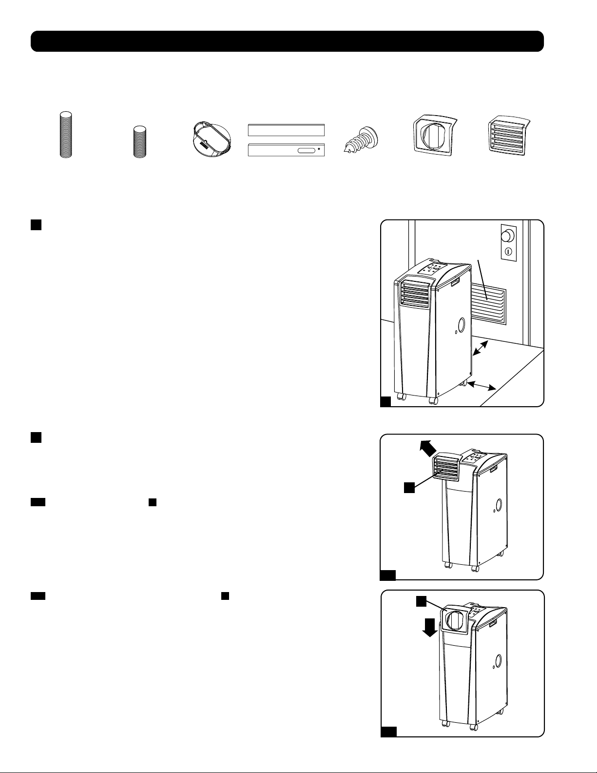
≥ 51 cм
≥ 51 cм
Стена
645 кв. cм
Вентиляционное
отверстие
(в ограниченных
пространствах)
1
2-1
2-2
A
A
44
становка
Внимание! После извлечения устройства из транспортировочного контейнера проверьте его на предмет наличия повреждений
или отсутствующих деталей (см. приведенный ниже перечень деталей). В случае выявления какой-либо проблемы обращайтесь за
помощью по адресу: tripplite.com/support. Не пытайтесь эксплуатировать устройство при наличии повреждений.
Перечень комплектующих:
1
Размещение устройства
Разместите устройство на гладкой и ровной поверхности рядом с заземленной розеткой сети переменного
тока с номинальным напряжением, соответствующим указанному на заводской табличке (находящимся
в диапазоне 90-110% от указанного значения). Вокруг устройства должно быть обеспечено достаточное
пространство для вентиляции, а его задняя стенка и вентиляционные отверстия должны находиться на
расстоянии не менее 51 см от стен или других препятствий. Устройство должно размещаться в месте, где
имеется удобный доступ к подвесному потолку или окну, с целью обеспечения возможности прокладки
вытяжного воздуховода по самому прямому и кратчайшему пути. Если вы планируете использовать
гибкий воздуховод охлаждения для сосредоточения потока холодного воздуха на какой-либо конкретной
корпусной стойке или элементе оборудования, расположите устройство кондиционирования вблизи
запланированной корпусной стойки или элемента оборудования с целью обеспечения возможности
прокладки воздуховода охлаждения по самому прямому и кратчайшему пути.
Внимание! Не используйте шнур-удлинитель для подключения устройства к розетке
сети переменного тока. Используйте только шнур питания, поставляемый в комплекте с
устройством.
Внимание! Если устройство будет работать в условиях ограниченного пространства (например,
в монтажном шкафу), то для поддержания эффективного воздухообмена необходимо обеспечить
подачу к устройству добавочного воздуха. Для обычного монтажного шкафа достаточный объем
добавочного воздуха обеспечивается вентиляционным отверстием площадью не менее 645 кв. см у
нижнего края дверцы. Для получения более подробной информации ознакомьтесь с действующими
строительными нормами и правилами.
Шланг для отвода отработанного воздуха не показан (см. раздел 3).
2
Подсоединение воздуховода охлаждения (опционально)
Жалюзийная вставка, установленная в выходное отверстие на заводе-изготовителе, рассчитана
на охлаждение помещений. Если вы планируете охлаждать какое-либо помещение, переходите
к шагу 3, минуя шаг 2. Если вы планируете использовать гибкий воздуховод охлаждения для
сосредоточения потока холодного воздуха на каком-либо конкретном элементе оборудования или
корпусной стойке, следуйте приведенным ниже указаниям.
2-1
Выньте жалюзийную вставку
A
из выходного отверстия, потянув за нее по направлению
наружу и вверх.
Вытяжной воздуховод
(длинная трубка)
Воздуховод
охлаждения
(короткая трубка)
Переходник вытяжного
воздуховода
Регулируемая
вытяжная панель
(2 секции)
Саморез 2 переходника
воздуховодов
(1 из которых
устанавливается на
заводе-изготовителе)
Жалюзийная вставка
(устанавливается в
выходное отверстие на
заводе-изготовителе)
2-2
Совместите переходник воздуховода охлаждения
A
с выходным отверстием и вставьте его с
нажимом до щелчка.
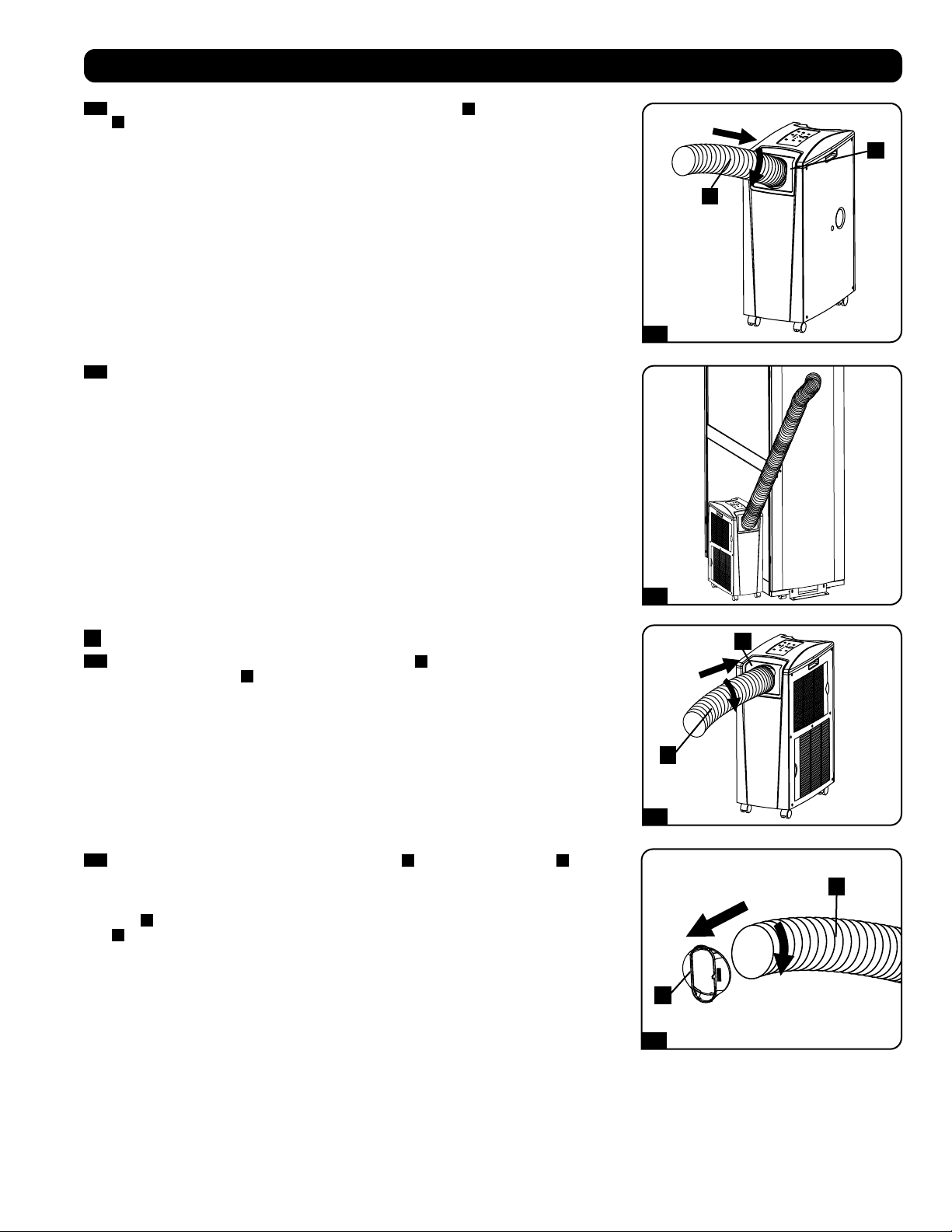
1
2
1
2
1
2
2-3
2-4
3-1
3-2
A
A
B
B
A
B
45
2-3
Подсоедините гибкий воздуховод охлаждения (короткая трубка
A
) к своему переходнику
B
. Совместите воздуховод с круглым отверстием переходника, надавите на него вниз и
вращайте его по часовой стрелке до тех пор, пока он прочно не ввинтится в переходник.
становка
2-4
Расположите противоположный конец воздуховода охлаждения вблизи воздухозаборного
отверстия охлаждаемого устройства или корпусной стойки, проведя его по наиболее
прямому и короткому пути. Если вы планируете охлаждение корпусной стойки, расположите
конец воздуховода охлаждения над перфорированной поверхностью вблизи верхнего
края передней дверцы корпуса (или у верхнего края группы устройств, нуждающихся
в охлаждении). Холодный воздух опустится вниз и распределится по воздухозаборным
отверстиям в передней части корпусной сойки.
3
Подсоединение вытяжного воздуховода
3-1
Вставьте гибкий вытяжной воздуховод (длинная трубка
A
) в отверстие для отвода
отработанного воздуха
B
. расположенное в задней панели устройства. Совместите
воздуховод с круглым отверстием для отвода, надавите на него внутрь и вращайте его по
часовой стрелке до тех пор, пока он прочно не ввинтится в отверстие для отвода.
3-2
На противоположный конец вытяжного воздуховода
A
наденьте его переходник
B
.
Совместите воздуховод с круглым отверстием переходника, надавите на него внутрь и
вращайте его по часовой стрелке до тех пор, пока он прочно не ввинтится в переходник. Если
вы планируете проводку вытяжного воздуховода через подвесной потолок, переходите к
шагу
4
. Если вы планируете проводку вытяжного воздуховода через окно, переходите к шагу
5
.
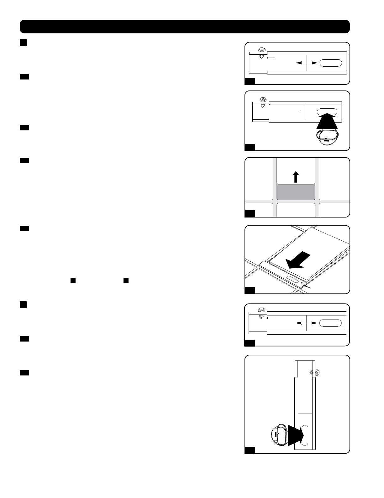
Саморез
Саморез
4-1
5-1
4-2
5-2
4-3
4-4
Потолочная панель
(снизу)
Потолочная панель
(сверху)
Вытяжная панель
46
становка
4
Проводка вытяжного воздуховода через подвесной потолок
Внимание! Для некоторых потолков может потребоваться измененный порядок установки.
Пользователь должен установить пригодность оснастки и предполагаемых процедур до
начала установки. Процедуры, описанные в настоящем руководстве, могут не подходить
для всех вариантов применения.
4-1
Выберите съемную панель подвесного потолка вблизи устройства с целью обеспечения
возможности проводки гибкого вытяжного воздуховода по наиболее прямому и короткому
пути. Измерьте ширину потолочной панели, включая ту ее часть, которая располагается
на решетке потолка. Соедините две секции регулируемой вытяжной панели, а затем
отрегулируйте ее по ширине потолочной панели. После установки нужной ширины вытяжной
панели зафиксируйте ее при помощи самореза, поставляемого в комплекте.
Примечание. Ширина вытяжной панели регулируется в диапазоне от 52,1 до 104,1 см. В
некоторых установках может требоваться подгонка размеров вытяжной панели.
4-2
Вставьте переходник вытяжного воздуховода в овальное отверстие регулируемой вытяжной
панели. Переходник защелкнется в нужном положении.
4-3
Сдвиньте потолочную панель в сторону и поместите вытяжную панель в межпотолочное
пространство. Вытяжная панель должна разместиться поверх потолочной решетки.
Примечание. Для обеспечения достаточного воздухообмена высота свободного
пространства над вытяжной панелью должна составлять не менее 25,4 см.
4-4
Передвиньте потолочную панель обратно на свое место таким образом, чтобы она примкнула
к вытяжной панели и закрыла собой все щели в потолке. Максимальную эффективность
охлаждения обеспечит герметичное уплотнение. Если установка производится на длительное
время, подрежьте потолочную панель таким образом, чтобы она не перекрывала собой
потолочную решетку.
Примечание. Гибкий вытяжной воздуховод может растягиваться на длину не более 300 см.
Обеспечьте его прохождение по наиболее прямому и короткому пути. Чрезмерное изгибание
или натягивание воздуховода будет снижать эффективность охлаждения.
По завершении шага
4
, переходите к шагу
6
.
5
Вытяжка через окно
Внимание! Для некоторых окон может потребоваться измененный порядок установки.
Пользователь должен установить пригодность оснастки и предполагаемых процедур до
начала установки. Процедуры, описанные в настоящем руководстве, могут не подходить
для всех вариантов применения.
5-1
Измерьте оконный проем. Соедините две секции регулируемой вытяжной панели, а затем
отрегулируйте ее по ширине оконного проема. После установки нужной ширины вытяжной
панели зафиксируйте ее при помощи самореза, поставляемого в комплекте.
Примечание. Ширина вытяжной панели регулируется в диапазоне от 52,1 до 104,1 см. Она
подходит как для вертикального, так и для горизонтального монтажа.
5-2
Вставьте переходник вытяжного воздуховода в овальное отверстие регулируемой вытяжной
панели. Переходник защелкнется в нужном положении.
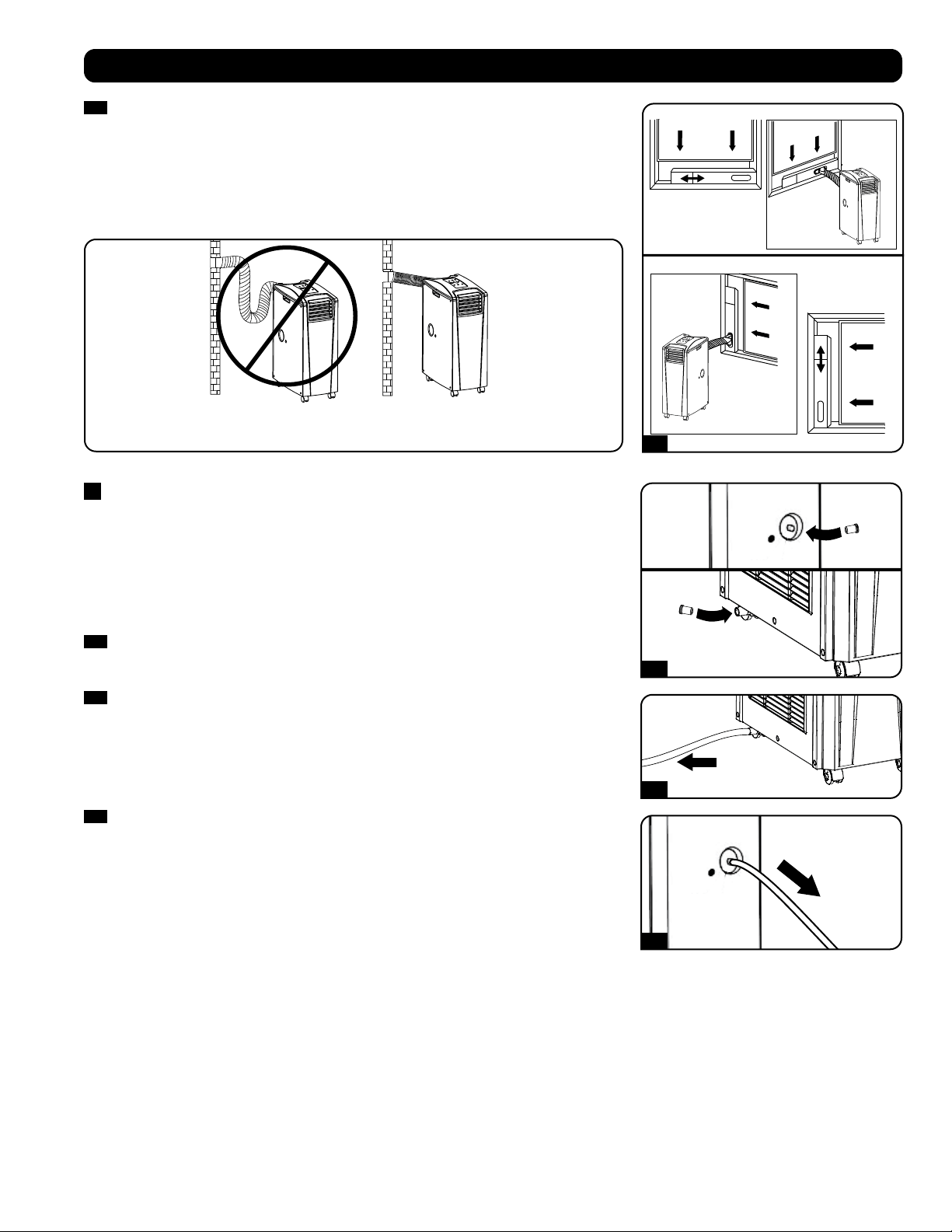
Горизонтальная
установка в
оконном
проеме
Вертикальная
установка в
оконном
проеме
НЕПРАВИЛЬНО ПРАВИЛЬНО
5-3
6-1
6-2
6-3
47
становка
5-3
Вставьте вытяжную панель в оконный проем и закройте окно при установленной вытяжной
панели. Максимальную эффективность охлаждения обеспечит герметичное уплотнение.
Примечание. Для обеспечения достаточного воздухообмена глубина свободного
пространства за вытяжной панелью должна составлять не менее 25,4 см.
Примечание. Гибкий вытяжной воздуховод может растягиваться на длину не более 300 см.
Обеспечьте его прохождение по наиболее прямому и короткому пути. Чрезмерное изгибание
или натягивание воздуховода будет снижать эффективность охлаждения.
6
Установка сливной пробки
Внимание! Встроенный осушитель устройства не будет функционировать до тех пор, пока
сливная пробка не будет вставлена в водовыпускное отверстие.
При работе устройства в режиме охлаждения или осушения образуется конденсат. Устройство
имеет встроенный осушитель, позволяющий отводить конденсат с вытягиваемым потоком
отработанного воздуха. Данная возможность позволяет устройству работать в течение
неограниченного времени без необходимости опорожнения резервуара для сбора воды.
Устройство поставляется в комплекте с верхней и нижней пробками, установленными на заводе-
изготовителе.
6-1
Режим охлаждения с повторным испарением
Для обеспечения возможности повторного испарения конденсата обе пробки должны
оставаться на своих местах.
6-2
Режим охлаждения без повторного испарения
Для использования режима охлаждения без повторного испарения конденсата выньте
нижнюю сливную пробку и самостоятельно проведите отводную линию к системе внешнего
дренажа. При этом верхняя сливная пробка должна оставаться на своем месте.
6-3
Режим осушения
При использовании устройства в режиме осушения выньте верхнюю сливную пробку
и самостоятельно проведите отводную линию к системе внешнего дренажа. При этом
нижняя сливная пробка должна оставаться на своем месте. Это позволит удалять из воздуха
максимально возможное количество влаги.
Примечание. В случае засорения дренажной системы конденсат накапливается в небольшой
внутренней емкости. Если дренажная система не будет прочищена до момента заполнения
внутренней емкости, то произойдет автоматическое отключение устройства.
Внимание! Перед подключением устройства к специализированной дренажной
системе его следует выключить и отсоединить от сети электропитания. Устройство,
включенное в сеть, представляет потенциальную опасность поражения электрическим
током.
Работа при низких температурах
Устройство кондиционирования воздуха представляет собой высокопроизводительный кондиционер, способный выдавать на выходе воздух,
охлажденный до очень низких температур. При использовании данного устройства в уже охлажденных средах (имеющим температуру не выше
20°C) компания Tripp Lite рекомендует использовать только режим осушения (Dehumidify Mode). Это позволит устройству продолжать процесс
вспомогательного охлаждения, избегая при этом проблем с обледенением испарителя, вызываемых низкой температурой в помещении.
Примечание. Если система вентиляции, установленная в вашем здании, запрограммирована на снижение эффективности охлаждения в
ночное время и выходные дни, функционирует с периодическими отключениями или имеет ограниченную холодопроизводительность, то
вы можете оказаться перед необходимостью рассмотрения вариантов, представляющих собой альтернативу штатной установке. Данное
изделие предназначено для использования в качестве вспомогательного охлаждающего устройства и не может компенсировать существенные
колебания температуры или влажности во всем здании.
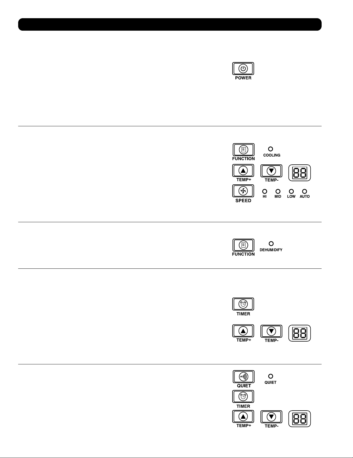
48
сплуатация
Внимание! Перед началом эксплуатации данного устройства произведите его установку согласно указаниям, приведенным в разделе “Установка”.
Питание
Включайте и выключайте устройство путем нажатия кнопки “POWER”.
Во избежание возможных перегрузок цепей в момент пуска устройство имеет трехминутную
задержку включения компрессора.
Возможность автоматического повторного пуска
При восстановлении питания после прекращения подачи электроэнергии происходит
автоматическое включение и возобновление работы устройства. При этом устройство
будет использовать те же настройки, которые использовались им непосредственно перед
прекращением подачи электроэнергии. Примечание. В случае кратковременного прекращения
подачи электроэнергии, перед возобновлением нормальной работы устройство будет в течение
трех минут только вращать вентилятор. Эта задержка дает возможность сброса давления в
компрессоре с целью обеспечения правильного функционирования устройства при переходе в
режим охлаждения.
Режим охлаждения
Нажатие кнопки “FUNCTION” обеспечивает циклическое изменение между режимами охлаждения
и осушения. При работе устройства в режиме охлаждения горит светодиодный индикатор
“COOLING”.
Для установки требуемой температуры в режиме охлаждения пользуйтесь кнопками TEMP+
и TEMP-. Установленное значение температуры отображается на цифровом индикаторе.
Непосредственно после установки желаемое значение подтверждается пятикратным миганием,
после чего на индикаторе отображается текущее значение комнатной температуры.
Циклическое переключение между высокой, средней и низкой скоростями вращения вентилятора
производится нажатием кнопки “FAN SPEED”. Выбранная скорость вращения вентилятора
подтверждается включением соответствующего светодиодного индикатора. При установке
скорости в режим AUTO устройство выбирает скорость вращения вентилятора автоматически
исходя из значений заданной и фактической температуры окружающего воздуха. Если температура
окружающего воздуха находится ниже заданного значения, то вентилятор будет вращаться, а
светодиодный индикатор “COOLING” будет мигать, указывая на то, что компрессор отключен. При
возобновлении режима охлаждения светодиодный индикатор “COOLING” непрерывно горит.
Режим осушения
Нажатие кнопки “FUNCTION” обеспечивает циклическое изменение между режимами охлаждения
и осушения.
При переходе в режим осушения загорается светодиодный индикатор “DEHUMIDIFY”. В режиме
осушения вентилятор вращается с постоянной скоростью, а регуляторы температуры не
действуют. Для обеспечения оптимальной работы в режиме осушения закройте окна и двери,
выньте верхнюю сливную пробку и проведите отводную линию к системе внешнего дренажа.
Таймер
Кнопка “TIMER” позволяет задавать время автоматического включения или отключения устройства.
Таймер включения (Примечание. Для приведения в действие функции “Таймер включения”
устройство должно быть выключено. Перед тем, как привести в действие функцию “Таймер
включения”, убедитесь в правильной установке режима, уровня температуры и скорости
вращения вентилятора.) Запустите таймер нажатием кнопки “TIMER”. Установите время задержки
включения устройства (в часах) с помощью кнопок TEMP+ и TEMP-. На цифровом индикаторе
отобразится установленное количество часов. Установка данного значения будет подтверждена
его пятикратным миганием на экране, после чего он возвратится в режим отображения текущей
температуры.
Таймер отключения (Примечание. Для приведения в действие функции “Таймер отключения”
устройство должно быть включено.) Запустите таймер нажатием кнопки “TIMER”. Установите
время задержки отключения устройства (в часах) с помощью кнопок TEMP+ и TEMP-. На цифровом
индикаторе отобразится установленное количество часов. Установка данного значения будет
подтверждена его пятикратным миганием на экране, после чего он возвратится в режим
отображения текущей температуры.
Режим бесшумной работы
В устройстве предусмотрен режим бесшумной работы, регулирующий охлаждение с помощью
таймера и микропроцессора в целях обеспечения более тихой работы устройства в тех случаях,
когда уровень шума является критичным показателем.
Для приведения данного режима в действие нажмите кнопку “QUIET”. При этом загорается
светодиодный индикатор Quiet. Установите желаемый уровень температуры, а затем установите
таймер продолжительности цикла бесшумной работы устройства. На протяжении данного цикла
память микропроцессора корректирует заданное значение температуры на 0,5°C каждые 30 минут
до момента достижения желаемой температуры. После достижения этой температуры устройство
поддерживает ее на протяжении установленного периода времени.
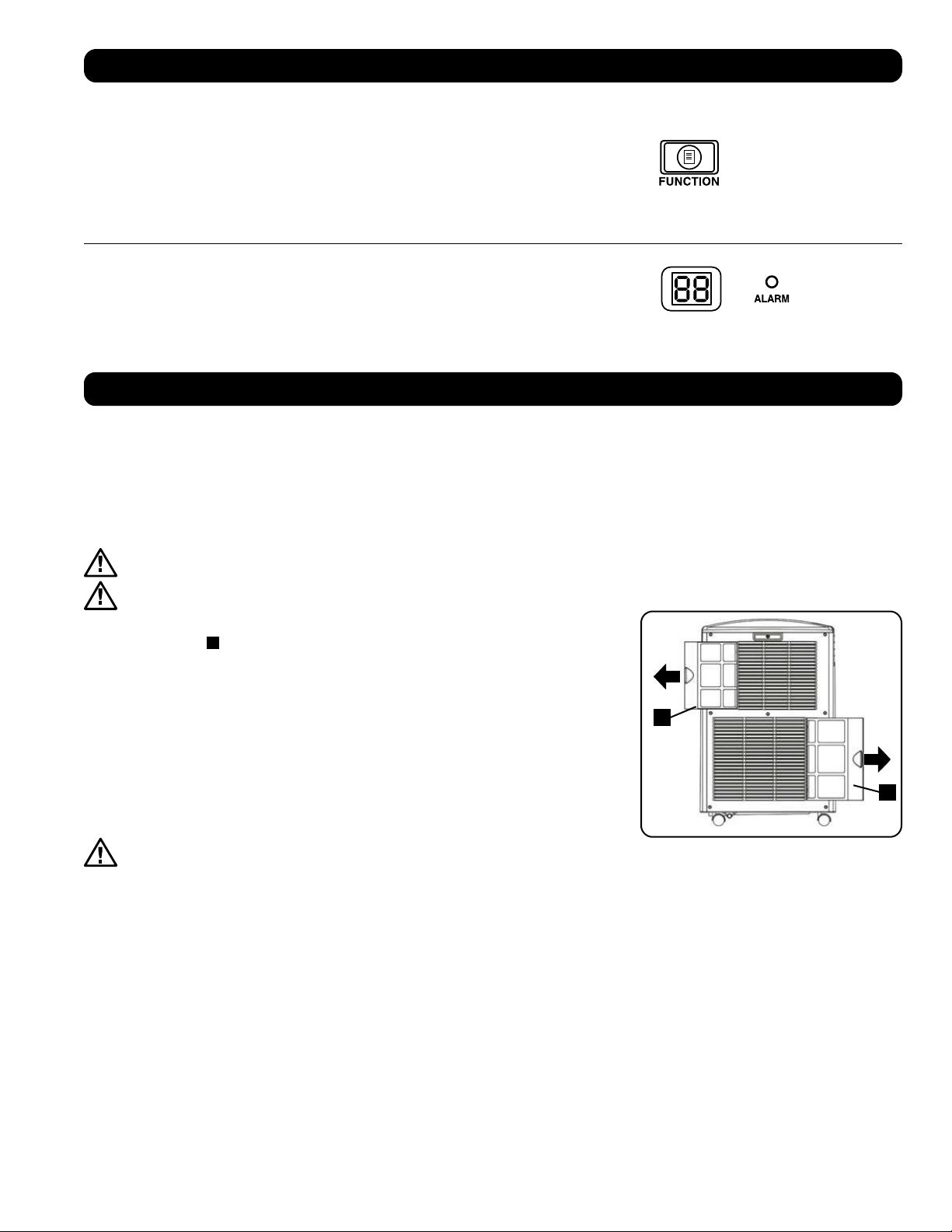
A
A
49
сплуатация
Очистка и Техническое обслуживание
Регулярно производите очистку кондиционера, а также очистку или замену фильтров для обеспечения его максимальной производительности и КПД,
продления срока его службы и сохранения гарантии на случай выхода из строя.
Примечание. Перед очисткой кондиционера обязательно отключайте его от электросети
Очистка воздушных фильтров
Воздушные фильтры необходимо содержать в чистоте и без пыли. При загрязнении этих фильтров или их забивании пылью снижается эффективность
охлаждения и может ухудшаться качество воздуха. Компания Tripp Lite рекомендует очищать фильтры с периодичностью не более двух недель. Если
устройство используется в запыленной среде, фильтры могут нуждаться в очистке или замене еженедельно.
Перед очисткой фильтров выключите устройство и отключите его от сети! Устройство, включенное в сеть, представляет
потенциальную опасность поражения электрическим током.
Никогда не включайте кондиционер без фильтра.
1. Выключите устройство и отключите его от сети.
2. Извлеките фильтры
A
выдвинув их из корпуса.
3. Удалите скопившиеся в фильтре пыль и грязь при помощи пылесоса или выбейте их путем
легкого постукивания.
4. Промойте фильтры теплой водой с добавлением нейтрального моющего средства. Не мойте
фильтры в посудомоечной машине и не используйте агрессивные моющие средства или
химические продукты. После промывания дайте фильтрам возможность полностью высохнуть на
воздухе.
Примечание. Не используйте для очистки фильтров воду при температуре выше 40°C.
5. Установите фильтры снова, задвинув их обратно на свои первоначальные места.
6. Подключите устройство к сети и продолжайте использовать как обычно.
Очистка корпуса
Перед очисткой фильтров выключите устройство и отключите его от сети! Устройство,
включенное в сеть, представляет потенциальную опасность поражения электрическим током.
1. Выключите устройство и отключите его от сети.
2. Протрите корпус сухой мягкой тряпкой. При необходимости смочите тряпку теплой водой. Ни в коем случае не используйте абразивные
химические средства, летучие вещества, бензин, бензол, разбавители, моющие средства, ткани с химической обработкой и другие агрессивные
химикаты или чистящие растворы, которые могут испортить внешний вид корпуса. Нe переливайте воду непосредственно над устройством и
не заливайте ее в рабочие элeменты. Этo приводит к опасности удара электрическим током и повреждения электрических деталей и изоляции
электропроводки.
3. Очистите пространство между дефлекторами при помощи щетки с мягкой щетиной.
4. Осторожно очистите змеевики конденсатора с помощью пылесоса.
Изменение температурных единиц
Устройство может отображать температуру как в градусах Цельсия, так и в градусах Фаренгейта.
По умолчанию в устройстве SRCOOL12K установлены градусы Фаренгейта, а в устройстве
SRXCOOL12K/SRXCOOL12KA/SRXCOOL12KB – градусы Цельсия.
Для переключения между режимами отображения температур переведите устройство в режим
ожидания. Устройство кондиционирования воздуха находится в режиме ожидания, когда оно
включено в сеть переменного тока без подачи питания. Затем нажмите кнопку “FUNCTION”
и удерживайте ее в течение 10 секунд. Для того чтобы проверить, изменились ли единицы
измерения температуры, включите питание устройства.
Предупредительный сигнал
При заполнении емкости для воды устройство отображает на своем экране сообщение “E4”.
Для восстановления нормальной работы отключите устройство, выньте сливную пробку и
вылейте из него избыточную воду. Вставьте пробку на место и включите устройство для начала
охлаждения
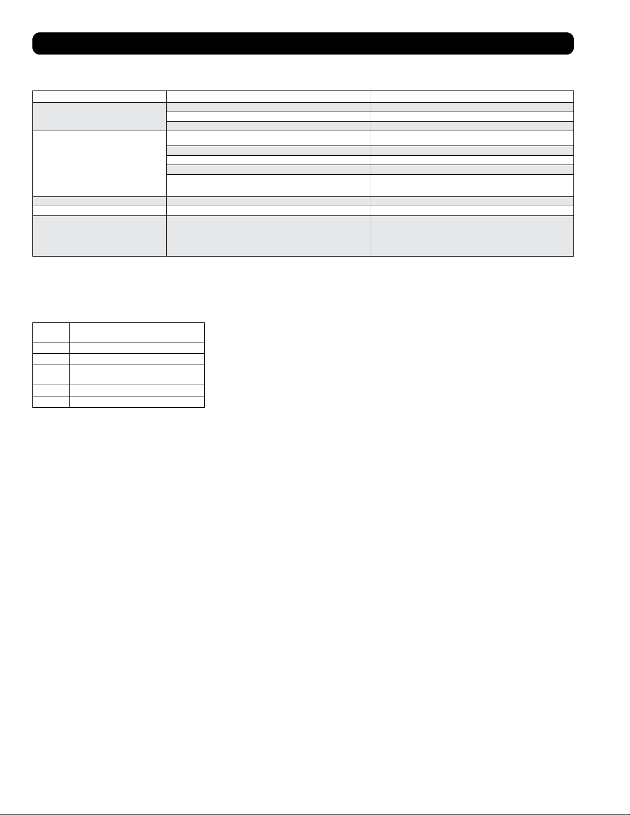
50
ление и устранение неисправностей
Ознакомьтесь с приведенными ниже возможными вариантами решения проблем. В случае сохранения возникшей проблемы посетите страницу
tripplite.com/support для получения технической поддержки.
Проблема Возможная причина Возможное решение
Устройство не работает. Устройство выключено. Включите устройство. (См. раздел “Эксплуатация”.)
Устройство не включено в сеть. Включите устройство в подходящую для него розетку электрической сети.
Отсутствует сетевое электропитание. Проверьте целостность предохранителей и положение автоматического выключателя.
Неудовлетворительная эффективность охлаждения. Заблокирован канал для выпуска или забора воздуха. Убедитесь в том, что все воздуховоды и воздухозаборные отверстия свободны от каких-
либо препятствий.
Установленное значение температуры слишком высоко. Отрегулируйте настройку температуры.
Установленная скорость вращения вентилятора слишком низка. Отрегулируйте настройку вентилятора.
Воздушные фильтры загрязнены. Очистите воздушные фильтры.
Мощность, потребляемая оборудованием в корпусной стойке, размер помещения
или температура окружающего воздуха превосходят холодопроизводительность
одиночного устройства.
Установите дополнительные модули или обратитесь в компанию Tripp Lite за
вспомогательными решениями, подходящими для вашей системы.
Из устройства течет вода. Не установлена сливная пробка. Вставьте сливную пробку в водовыпускное отвестие. (См. раздел “Установка”.)
Устройство производит чрезмерный шум и вибрации. Устройство установлено на неровной или неустойчивой поверхности. Переместите устройство на ровную и устойчивую поверхность.
В данном устройстве возможно образование льда или
инея.
Устройство работает в среде с повышенной влажностью. ВАРИАНТ 1: Выключите устройство и дайте ему возможность разморозиться. После
размораживания обеспечьте его работу с высокой скоростью вращения вентилятора
(режим HIGH).
ВАРИАНТ 2: Выключите устройство и дайте ему возможность разморозиться. После
размораживания используйте устройство в режиме осушения (DEHUMIDIFY MODE) или
задайте более высокое значение желаемой температуры.
Коды выводимые на дисплей
Коды ошибок
Устройство Tripp Lite SRCOOL12K/SRXCOOL12K/SRXCOOL12KA/SRXCOOL12KB имеет возможность непрерывно контролировать свою работу. В случае
возникновения ошибки на дисплее отображается один из пяти нижеперечисленных кодов ошибок:
Код
ошибки
Описание
E0 Отказ внутренней связи
E1 Отказ датчика температуры помещения
E2 Отказ внутреннего датчика
температуры
E3 Отказ системы циркуляции хладагента
E4 Заполнение емкости для сбора воды
Для устранения ошибки с кодом E4 необходимо опорожнить емкость для сбора воды. Более
подробную информацию см. в пункте “Сигнализация” раздела “Эксплуатация”.
При возникновении ошибок с кодами E0, E1, E2 и E3 выполните следующие действия:
1. Перезагрузите устройство, отключив его от источника питания на 5 минут.
2. Снова подключите устройство к источнику питания.
3. Включите устройство.
В случае исчезновения ошибки продолжайте эксплуатацию устройства в обычном порядке. В
случае повторного возникновения ошибки обратитесь в компанию Tripp Lite за дальнейшими
указаниями.
Код dF
Код dF отображается в тех случаях, когда устройство SRCOOL12K/SRXCOOL12K/SRXCOOL12KA/SRXCOOL12KB выявляет какое-либо условие, при
котором змеевик работает при температуре ниже 1°C в течение более чем 15 минут.
Во время события, отображаемого кодом dF, вентиляторы устройства вращаются без подключения компрессора во избежание замерзания
испарителя. После подъема температуры змеевика выше 1°C компрессор возобновляет свою обычную работу.
При сохранении указанного условия устройство функционирует в слишком холодной среде. При температурах эксплуатации ниже 20°C компания
Tripp Lite рекомендует использовать устройство только в режиме осушения. Более подробную информацию см. в пункте Эксплуатация при низких
температурах раздела 6-3.
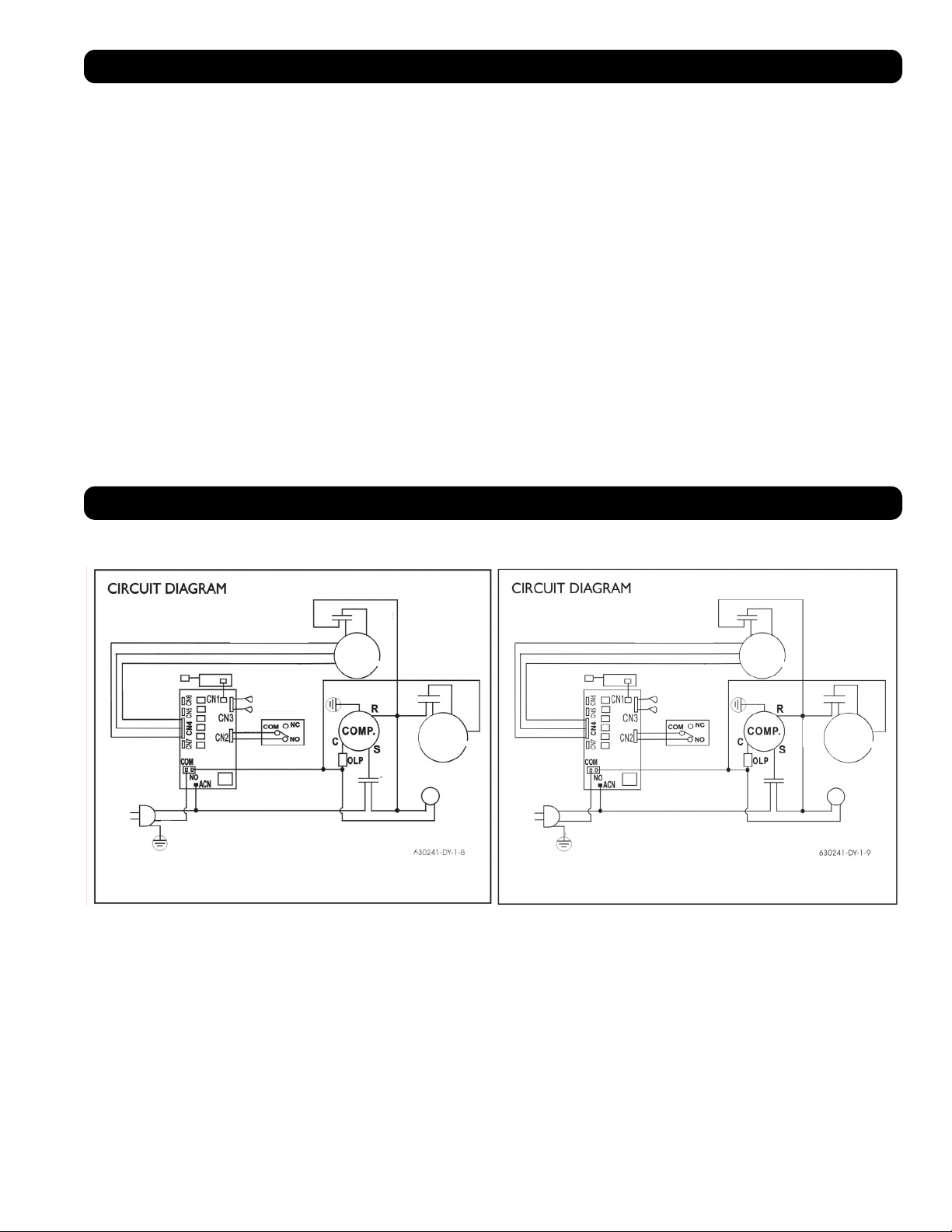
51
Хранение и техническое обслуживание
Хранение
Перед помещением данного устройства на хранение убедитесь в том, что его трубопроводы и воздуховоды надежно закреплены или демонтированы
и хранятся надлежащим образом. Также убедитесь в отсутствии внутри устройства остатков конденсата.
Обслуживание
На приобретенное вами изделие фирмы Tripp Lite распространяется действие гарантии, условия которой изложены в настоящем руководстве. Кроме
того, компания Tripp Lite предлагает различные Программы расширенной гарантии и Программы обслуживания на объекте. Для получения более
подробной информации о программах обслуживания приглашаем вас посетить интернет-страницу по адресу: tripplite.com/support. Перед возвратом
своего изделия в целях технического обслуживания просьба выполнить следующие действия:
1. Изучить приведенный в настоящем руководстве порядок монтажа и эксплуатации с целью убедиться в том, что возникшая проблема не является
результатом незнания или непонимания изложенных в нем указаний.
2. Если устранить проблему таким образом не удалось, не обращайтесь к дилеру и не возвращайте изделие ему, а посетите интернет-страницу по
адресу: tripplite.com/support.
3. Если возникшая проблема требует проведения технического обслуживания, зайдите на страницу: tripplite.com/support и пройдите по ссылке
Product Returns (Возврат изделий). Здесь вы можете запросить номер Returned Material Authorization (RMA – разрешение на возврат материалов),
который необходим для проведения технического обслуживания. При заполнении этой простой онлайн-формы заявки потребуется указать номер
модели и серийный номер вашего изделия, а также общие сведения о покупателе. Номер RMA вместе с указаниями по транспортировке будет
направлен вам по электронной почте. Действие гарантии не распространяется на какие-либо убытки (прямые, косвенные, последующие или
связанные с особыми обстоятельствами), понесенные в процессе транспортировки изделия в адрес компании Tripp Lite или ее авторизованного
сервисного центра. Стоимость транспортировки изделий в адрес компании Tripp Lite или ее авторизованного сервисного центра должна быть
оплачена авансом. Укажите номер RMA на внешней стороне упаковки. Если возврат изделия производится в период действия гарантии, то
приложите копию товарного чека продавца. Возврат изделия для проведения технического обслуживания должен производиться застрахованным
перевозчиком по адресу, указанному в ответе на запрос номера RMA.
Принципиальные электрические схемы
Приведенные ниже схемы представлены только в справочных целях. Внутри устройства нет деталей, обслуживаемых пользователем.
White - Белый
Yellow - Желтый
Brown - Коричневый
Orange - Оранжевый
Red -
Красный
White - Белый
Red -
Красный
Yellow - Желтый Yellow - Желтый
Red - Красный Red - Красный
Red -
Красный
White -
Белый
Black - Черный
White - Белый
Зеленый / Желтый
Green / Yellow
Draining Motor -
Электродвигатель
дренажного насоса
Water Full Switch - Выключатель
защиты от переполнения
емкости для сбора воды
White - Белый
Black - Черный
Green - Зеленый
Motor-Compressor Thermally Protected -
Мотор-компрессор с термозащитой
Принципиальные
электрические схемы
Remote Receiver -
Удаленный
приемник
Remote Receiver / Display
PCB - Удаленный приемник
/ Плата дисплея
Temperature Sensor -
Датчик температуры
Blue -
Синий
Motor Upper -
Верхний
электродвигатель
Motor Lower -
Нижний
электродвигатель
Принципиальные
электрические схемы
Motor-Compressor Thermally Protected -
Мотор-компрессор с термозащитой
Red -
Красный
Yellow - Желтый
Brown - Коричневый
Orange - Оранжевый
Draining Motor -
Электродвигатель
дренажного насоса
Red -
Красный
White -
Белый
Motor Lower -
Нижний
электродвигатель
Red -
Красный
White - Белый
Black - Черный
Green - Зеленый
White - Белый
Зеленый / Желтый
Green / Yellow
Black - Черный
Water Full Switch - Выключатель
защиты от переполнения
емкости для сбора воды
Remote Receiver -
Удаленный
приемник
Remote Receiver / Display
PCB - Удаленный приемник
/ Плата дисплея
Temperature Sensor -
Датчик температуры
Blue -
Синий
Motor Upper -
Верхний
электродвигатель
Fuse on PCB: 2A 250V - Предохранитель на плате: 2 А / 250 В
Принципиальная электрическая схема, SRCOOL12K Принципиальная электрическая схема, SRXCOOL12K, SRXCOOL12KA, SRXCOOL12KB

52
1111 W. 35th Street, Chicago, IL 60609 USA • tripplite.com/support
20-03-239 93-33FA_RevE
арантийные обязательства
ОГРАНИЧЕННАЯ ГАРАНТИЯ СРОКОМ 2 ГОДА (для США и Канады)
ОГРАНИЧЕННАЯ ГАРАНТИЯ СРОКОМ 1 ГОД (для всех остальных регионов)
Продавец гарантирует отсутствие изначальных дефектов материала или изготовления в течение 2 лет (для США и Канады) или 1 года (для всех остальных регионов) с момента первоначальной
покупки данного изделия при условии его использования в соответствии со всеми применимыми к нему указаниями. B случае проявления каких-либо дефектов материала или изготовления в течение
указанного периода Продавец осущеcтвляет ремонт или замену данного изделия иcключительно по своему усмотрению. Обслуживание по настоящей Гарантии производится только при условии
доставки или отправки вами бракованного изделия (с предварительной оплатой всех расходов по его транспортировке или доставке) по адресу: Tripp Lite, 1111 W. 35th Street, Chicago, IL 60609 USA.
Pасходы по обратной транспортировке изделия оплачиваются Продавцoм.
В отношении данной гарантии действуют следующие ограничения. Действие данной гарантии не распространяется на:
• Затраты на монтаж и настройку данного изделия или обучение работе с ним
• Повреждения в процессе транспортировки и любые повреждения, вызванные ненадлежащей упаковкой для транспортировки в авторизованный сервисный центр, а также использованием
недопустимого напряжения или другими нарушениями правил эксплуатации, включая ненадлежащее обслуживание, обращение или использование
• Незначительные поверхностные повреждения (например, царапины или вмятины)
• Естественный износ деталей или замену деталей, являющихся расходными материалами (таких как фильтры, картриджи, батареи)
• Служебные командировки в целях доставки, вывоза или ремонта, монтажа изделия или инструктирования по вопросам его надлежащего использования
• Повреждения или эксплуатационные проблемы, вызванные ненадлежащим использованием, нарушением правил использования, эксплуатацией с нарушением требований к ее условиям,
использованием в нарушение указаний, изложенных в руководстве пользователя, авариями, стихийными бедствиями, вредителями, пожарами, наводнениями, ненадлежащей установкой,
несанкционированным техническим обслуживанием, невыполнением планового технического обслуживания, несанкционированным монтажом или внесением несанкционированных изменений в
конструкцию, а также в случае использования в коммерческих или арендных целях
• Использование изделия в коммерческих или арендных целях
• Дополнительные комплектующие, вспомогательную оснастку и внешние декоративные элементы
• Изделия, в конструкцию которых были внесены изменения с целью эксплуатации в нарушение установленных требований
• Изделия с удаленными или неразличимыми серийными номерами
• Изделия с серийными номерами, признанными недействительными
• Ущерб, причиненный личному имуществу в связи с использованием изделия
• Замену или ремонт предохранителей, автоматических выключателей, проводки или водопроводно-канализационных коммуникаций, установленных на объекте
Гарантийные обязательства
нормативным требованиям
Присвоение идентификационных номеров согласно установленным нормам
В целях сертификации и идентификации согласно действующим нормативным требованиям, приобретенному вами изделию марки Tripp Lite присвоен уникальный серийный номер. Этот серийный
номер указан на паспортной табличке изделия вместе со всеми необходимыми отметками о разрешении на использование и прочими обязательными сведениями. При запросе каких-либо сведений о
соответствии данного изделия действующим нормам просьба указывать этот серийный номер. Серийный номер не следует путать с наименованием марки изделия или номером его модели.
Информация по выполнению требований Директивы об утилизации отходов электрического и электронного оборудования (WEEE) для покупателей и переработчиков
продукции компании Tripp Lite (на территории Европейского союза)
Примечание. Действие настоящего положения распространяется на изделия с нанесенным логотипом WEEE.
Согласно положениям Директивы WEEE и исполнительных распоряжений по ее применению, при покупке нового электрического или электронного оборудования производства
компании Tripp Lite потребители получают право на:
• продажу старого оборудования по принципу «один к одному» или на эквивалентной основе (в зависимости от конкретной страны);
• возврат нового оборудования для переработки после окончательной выработки его ресурса.
Не рекомендуется использовать данное оборудование в системах жизнеобеспечения в тех случаях, когда его сбой с большой вероятностью приведет к сбою оборудования жизнеобеспечения или
значительному снижению его безопасности или эффективности.
Компания Tripp Lite постоянно совершенствует свою продукцию. В связи с этим возможно изменение технических характеристик изделия без предварительного уведомления.