1
80-01-182 - 2023-09-06SS23161
ALLEN + ROTH
™
and logo design are
trademarks or registered trademarks of
LF, LLC. All rights reserved.
ITEM# 5228484 / 5228485
INSTALLER: Leave this manual with the appliance.
CONSUMER: Retain this manual for future reference.
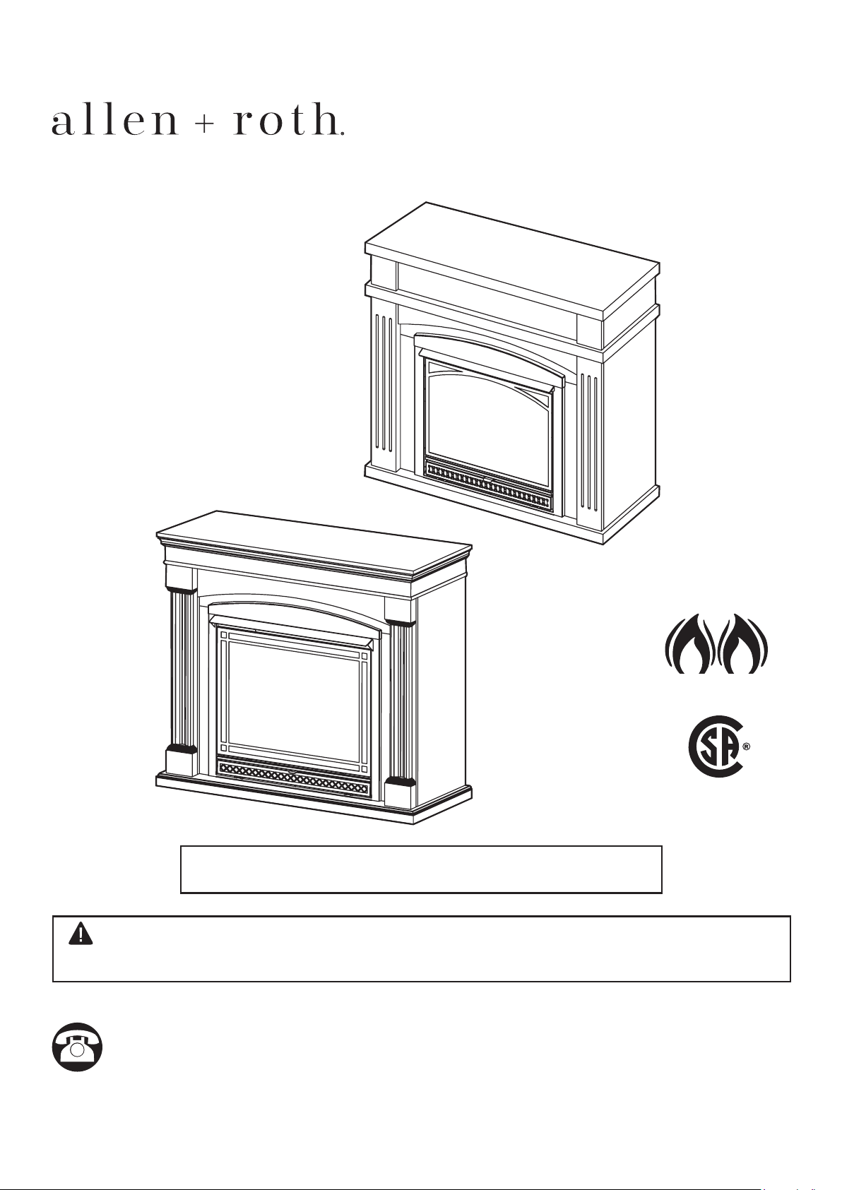
WARNING: This appliance is equipped for (Natural and Propane) gas. Field conversion is not
permitted other than between natural or propane gases.
Dual Fuel
ANS Z21.11.2 2019
NG LP
CUS
Patent Pending
Dual Fuel System
Questions, problems, missing parts? Before returning to your retailer, call our customer
service department at 1-877-447-4768, 8:30 a.m. –4:30 p.m., CST, Monday – Friday or email
us at customerservice@ghpgroupinc.com.
CUS
VENT-FREE GAS
DUAL FUEL FIREPLACE
MODEL # VFF-L25D / VFF-L32D
2
WARNING: Any safety screen or guard removed for servicing an appliance must be
replaced prior to operating the heater.
WARNING: When the appliance is installed directly on carpeting, tile or other combustible
material,otherthanwoodooring,theapplianceshallbeinstalledonametalorwoodpanel
extending the full width and depth of the appliance.
WARNING: Do not attempt to access or change the setting of the fuel selection means.
Access to and adjustment of the fuel selection means must only be a performed by a
quali�edservicepersonwhenconnectingthisappliancetoaspeci�edfuelsupplyatthe
time of installation.
Changeoftheselectorsettingtootherthanthefueltypespeci�edatthetimeofinstallation
could damage this appliance and render it inoperable.
The installer shall replace the access cover before completing the installation and operating
this appliance.
WARNING: IF THE INFORMATION IN THIS MANUAL IS NOT FOLLOWED
EXACTLY, A FIRE OR EXPLOSION MAY RESULT CAUSING PROPERTY
DAMAGE, PERSONAL INJURY OR LOSS OF LIFE.
CAUTION - FOR YOUR SAFETY
-DonotstoreorusegasolineorotherammablevaporsandIiquidsinvicinityofthis
or any other appliance.
WHAT TO DO IF YOU SMELL GAS
• Do not try to light any appliance.
• Do not touch any electrical switch; do not use any phone in your building.
• Immediately call your gas supplier from a neighbor’s phone. Follow the gas supplier’s
instructions.
•Ifyoucannotreachyourgassupplier,callthe�redepartment.
-Installationandservicemustbeperformedbyaquali�edinstaller,serviceagencyor
the gas supplier.
Thisisanunventedgas-�redheater.Itusesair(oxygen)fromtheroominwhichitis
installed. Provisions for adequate combustion and ventilation air must be provided.
Refer to Air For Combustion and Ventilation section on page 10-12 of this manual.
This appliance may be installed in an aftermarket, permanently located manufactured
(mobile)home,wherenotprohibitedbylocalcodes.Thisapplianceisonlyforusewith
propane or natural gas. This appliance is equipped with a simple means to switch between
propane and natural gas. Field conversion by any other means including the use of a kit is
not permitted.
3
WARNING: Read the Installation & Operating Instructions before using this appliance.
IMPORTANT: Read all instructions and warnings carefully before starting installation.
Failure to follow these instructions may result in possible injury to persons or a fire
hazard and will void the warranty.
TABLE OF CONTENTS
Speci�cations ................................................................................................................................... 3
Important Safety Information ............................................................................................................4
ProductIdenti�cation ........................................................................................................................ 6
Product Features .............................................................................................................................. 8
Unpacking......................................................................................................................................... 8
Arch Panel Assembly........................................................................................................................ 9
Preparing for Installation................................................................................................................. 10
Installation ...................................................................................................................................... 13
Operation ........................................................................................................................................ 26
Remote Control Operation.............................................................................................................. 28
Care and Maintenance ................................................................................................................... 35
Troubleshooting .............................................................................................................................. 37
Replacement Parts ......................................................................................................................... 40
Warranty ......................................................................................................................................... 44
SERVICE HINTS
When Gas Pressure Is Too Low
• Pilot will not stay lit.
• Burners will have delayed ignition.
•Fireplacewillnotproducespeci�edheat.
• For propane/LP units, propane/LP gas supply may be low.
You may feel your gas pressure is too low. If so, contact your local natural or propane/LP gas supplier.
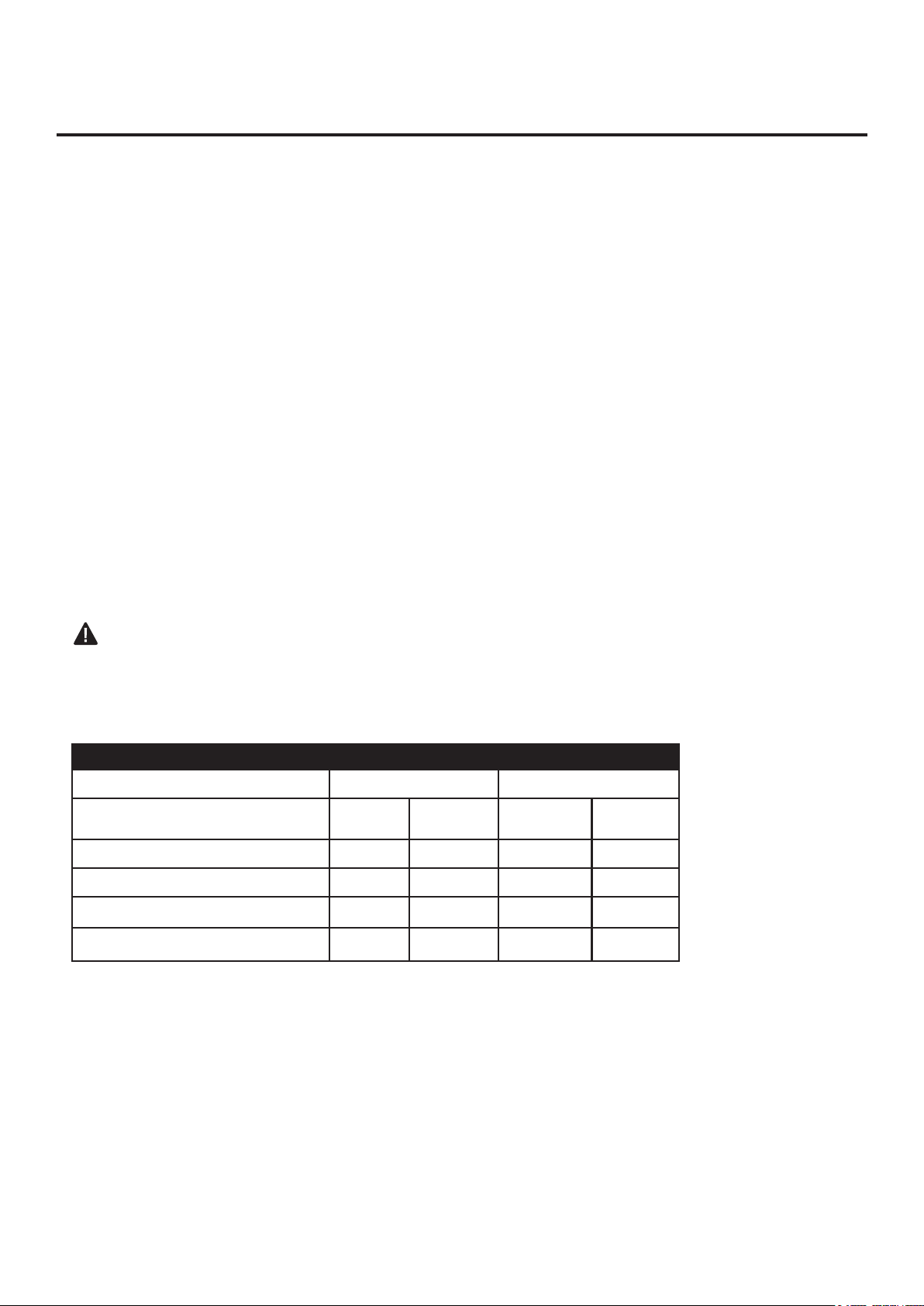
Model
VFF-L25D VFF-L32D
Input Rating 25,000 BTU/Hr 33,000 BTU/Hr
Minimum Input Rating
20,000
BTU/Hr
14,000
BTU/Hr
33,000
BTU/Hr
33,000
BTU/Hr
Gas Type LP NG LP NG
Manifold Pressure 10" W.C. 5" W.C. 10" W.C. 5" W.C.
Max. Inlet Pressure 14" W.C. 14" W.C. 14" W.C. 14" W.C.
Min. Inlet Pressure 11" W.C. 6" W.C. 11" W.C. 6" W.C.
4
IMPORTANT: Read this owner’s manual carefully and completely before trying to assemble, operate,
orservicethisheater.Improperuseofthisheatercancauseseriousinjuryordeathfromburns,�re,
explosion, electrical shock, and carbon monoxide poisoning.
IMPORTANT SAFETY INFORMATION
Onlyaquali�edinstaller,serviceagent,orlocalgassuppliermayinstallandservicethisproduct.
WARNING:Donotstoreorusegasolineorotherammablevaporsorliquidsinthevicinity
of this or any other appliance.
WARNING: This appliance can be used with propane or natural gas. It is shipped from the
factory adjusted for use with propane.
CARBON MONOXIDE POISONING: Earlysignsofcarbonmonoxidepoisoningresembletheu
with headaches, dizziness, or nausea. If you have these signs, the heater may not be working properly.
Get fresh air immediately! Have heater serviced. Some people are more affected by carbon monoxide
than others. These include pregnant women, people with heart or lung disease, people who are
anemic,thoseundertheinuenceofalcohol,andthoselivinginhighaltitudes.
NATURAL AND PROPANE/LP GAS: Natural and Propane/LP gases are odorless. An odor-making
agent is added to the gas. The odor helps you detect a gas leak. However, the odor added to the
gas can fade. Gas may be present even though no odor exists. Make certain you read and under-
stand all warnings. Keep this manual for reference. It is your guide to operating this heater safely.
WARNING:Anychangetothis�replace/heateroritscontrolscanbedangerous.
WARNING: Do not use any accessories not approved for use with this heater.
WARNING: Carefully supervise young children when they are in the room with the heater.
WARNING: Heater becomes very hot when operating. Keep children and adults away from hot
surfaces to avoid burns or clothing ignition. Heater will remain hot for a time after shutoff. Allow
surfaces to cool before touching.
WARNING: Keep the appliance area clear and free from combustible materials, gasoline, and
otherammablevaporsandliquids.
WARNING:Duetohightemperatures,locatethisapplianceoutoftraf�candawayfrom
furniture and draperies.
WARNING:Donotplaceclothingorotherammablematerialonorneartheappliance.Never
place any objects in the heater.
WARNING
This product and the fuels used to operate this product (liquid propane or natural gas), and the products of combustion
of such fuels, can expose you to chemicals including benzene, which is known to the State of California to cause cancer
and birth defects or other reproductive harm.
For more information go to www.p65Warnings.ca.gov
WARNING: FIRE, EXPLOSION, AND ASPHYXIATION HAZARD
Improper adjustment, alteration, service, maintenance, or installation of this heater or its controls can
cause death or serious injury.
Read and follow instructions and precautions in User's Information Manual provided with this heater.

5
SAFETY INFORMATION
1. This appliance is only for use with the type of gas indicated on the rating plate. This appliance is
not convertible for use with other gases.
2.
Do not place propane/LP supply tank(s) inside any structure. Locate propane/LP supply tank(s) outdoors.
3. If you smell gas
• Shut off gas supply.
• Do not try to light any appliance.
• Do not touch any electrical switch; do not use any phone in your building.
• Immediately call your gas supplier from a neighbor’s phone. Follow the gas supplier’s instructions.
•Ifyoucannotreachyourgassupplier,callthe�redepartment.
4. This�replaceshallnotbeinstalledinabedroomorbathroom.
5. Donotusethis�replaceasawood-burning�replace.Useonlythelogsprovidedwiththe�replace.
6. Do not add extra logs or ornaments such as pine cones, vermiculite or rock wool. Using these
added items can cause sooting. Do not add lava rock around base. Rock and debris could fall
intothecontrolareaof�replace.
7. This�replaceisdesignedtobesmokeless.Iflogseverappeartosmoke,turnoff�replaceand
callaquali�edserviceperson.Note:Duringinitialoperation,slightsmokingcouldoccurdueto
logcuringand�replaceburningmanufacturingresidues.
8. To prevent the creation of soot, follow the instructions in Care and Maintenance, page 35.
9. Beforeusingfurniturepolish,wax,carpetcleanerorsimilarproducts,turn�replaceoff.Ifheated,
the vapors from these products may create a white powder residue within burner box or on
adjacent walls or furniture.
10.This�replaceneedsfreshairventilationtorunproperly.This�replacehasanOxygenDepletion
Sensing(ODS)safetyshutoffsystem.TheODSshutsdownthe�replaceifnotenoughfreshair
isavailable.SeeAirforCombustionandVentilation,page10-12.If�replacekeepsshuttingoff,
see Troubleshooting, page 37.
11.Donotrun�replace
•Whereammableliquidsorvaporsareusedorstored.
• Under dusty conditions.
12.Donotusethis�replacetocookfoodorburnpaperorotherobjects.
13.Neverplaceanyobjectsinthe�replaceoronlogs.
14.Donotuse�replaceifanyparthasbeenunderwater.Immediatelycallaquali�edservicetechnician
toinspecttheroom�replaceandtoreplaceanypartofthecontrolsystemandanygascontrol
which has been under water.
15.Turnoffandunplug�replaceandletcoolbeforeservicing.Onlyaquali�edserviceperson
shouldserviceandrepair�replace.
16.Operating�replaceaboveelevationsof4,500feetcouldcausepilotoutage.
17.
Donotoperate�replaceiflogisbroken.Donotoperate�replaceiflogischipped(dime-sizedorlarger).
18. To prevent performance problems, do not use propane/LP fuel tank of less than 100 lb. capacity.
19. Provide adequate clearances around air openings.
QUALIFIED INSTALLING AGENCY
Onlyaquali�edagencyshouldinstall
and replace gas piping, gas utilization
equipment or accessories, and repair and
equipmentservicing.Theterm"quali�ed
agency"meansanyindividual,�rm,
corporation, or company that either in
person or through a representative is
engaged in and is responsible for:
a) Installing, testing, or replacing gas piping or
b) Connecting, installing, testing, repairing, or
servicing equipment; that is experienced in such
work; that is familiar with all precautions required;
and that has complied with all the requirements of
the authority having jurisdiction.
6
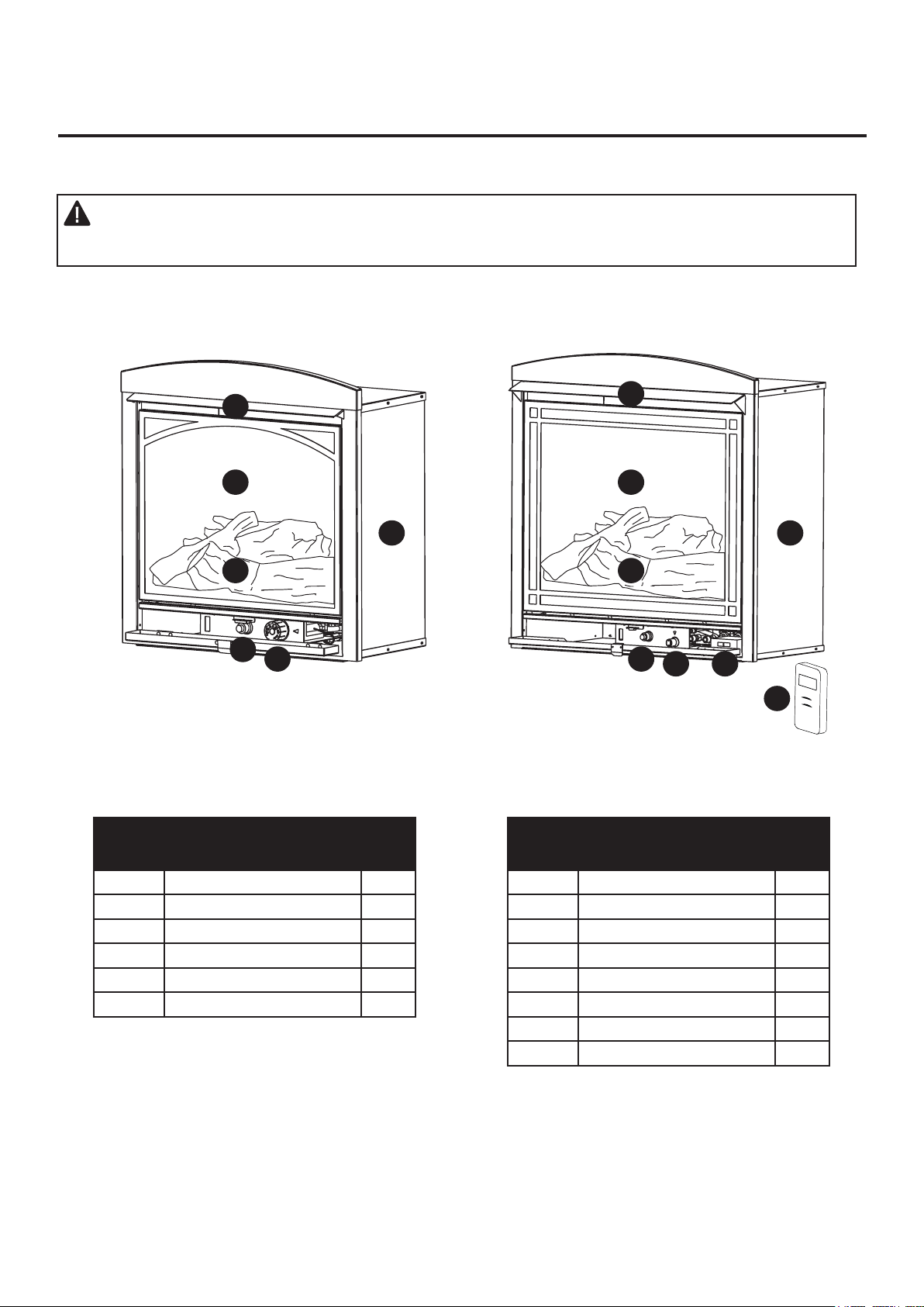
PRODUCT IDENTIFICATION
WARNING:This�replaceisdesignedforusewiththemantelcabinetprovided.Installing
the�replacecabinetwithouttheprovidedmantelorsubstitutinganothermantelwillvoid
the warranty and could result in property damage and personal injury.
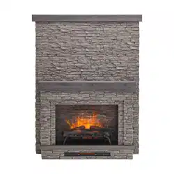
Fig. 1 - Vent-Free Dual Fuel Fireplace
VFF-L25DVFF-L25D
VFF-L25D
VFF-L32D
VFF-L32D
NOTE:The�replaceisinstalledintothemantelthroughthefrontopeningofthemantelcabinet.
A
C
D
A
B
C
D
PART DESCRIPTION QTY
A Fireplace Cabinet 1
B Hood 1
C Screen 1
D Log 1
E Ignitor Button 1
F Control Knob 1
PART DESCRIPTION QTY
A Fireplace Cabinet 1
B Hood 1
C Screen 1
D Log 1
E Ignitor Button 1
F Control Knob 1
G EI Receiver 1
H Remote Transmitter 1
E
F G
H
E
F
B

7
PRODUCT IDENTIFICATION
VFF-L25D
VFF-L25D
VFF-L32D
VFF-L32D
A
A
G
G
D
D
B
B
F
F
E
E
C
C
AA BB
CC DD
PART DESCRIPTION QTY
A Top Panel 1
B Base 1
C Left Side Panel 1
D Right Side Panel 1
E Left Front Panel 1
F Right Front Panel 1
G Upper Front Panel 1
AA Connector 18
BB Short Bolt 54
CC Long Bolt 4
DD Washer 4
PART DESCRIPTION QTY
A Top Panel 1
B Base 1
C Left Side Panel 1
D Right Side Panel 1
E Left Front Panel 1
F Right Front Panel 1
G Upper Front Panel 1
AA Connector 19
BB Short Bolt 57
CC Long Bolt 4
DD Washer 4

8
UNPACKING
1.Removethe�replacecabinetandthewoodmantelfromthecarton.Thelogsetiswrapped
andpackedinsidethe�replacecabinet.
2.Removeallprotectivepackagingappliedto�replaceforshipment.
3. Make sure your wood mantel includes one hardware packet.
4.Check�replaceforanyshippingdamage.If�replaceisdamaged,callGHPGroup,Inc.,
at 1-877-447-4768. Please do not return it to the store.
SAFETY PILOT
This heater has a pilot with an Oxygen Depletion Sensing (ODS) safety shutoff system.
The ODS/pilot shuts off the heater if there is not enough fresh air and cuts off main burner gas
intheeventofameout.
ELECTRIC PUSH BUTTON IGNITION SYSTEM
This heater is equipped with an electronic push button control system. This system requires
one AAA battery (provided).
THERMOSTAT HEAT CONTROL
The control automatically cycles the burner on and off to maintain a desired room temperature.
See page 29.
DUAL FUEL CAPABILITY
Your heater is equipped to operate on either propane or natural gas. The heater is shipped from the
factory ready for connecting to propane. The heater can easily be changed to natural gas by having
yourquali�edinstallerfollowtheinstructionsonpage20andthemarkingsontheheater.
LOCAL CODES
Install and use heater with care. Follow all codes. In the absence of local codes, use the latest
edition of The National Fuel Gas Code, ANSI Z223.1, also known as NFPA 54*.
*Available from:
American National Standard Institute, Inc. National Fire Protection Association, Inc.
1430 Broadway 1 Batterymarch Park
New York, NY 10018 Quincy, MA 02269-9101
This heater is designed for vent-free operation. State and local codes in some areas prohibit the use
of vent-free heaters.
PRODUCT FEATURES
StateofMassachusetts:Theinstallationmustbemadebyalicensedplumberorgas�tterin
theCommonwealthofMassachusetts.Sellersofunventedpropaneornaturalgas-�red
supplemental room heaters shall provide to each purchaser a copy of 527 CMR 30 upon sale
of the unit.
IntheStateofMassachusetts,unventedpropaneornaturalgas-�redspaceheatersshall
be prohibited in bedrooms and bathrooms.
In the State of Massachusetts the gas cock must be a T-handle type. The State of
Massachusettsrequiresthataexibleapplianceconnectorcannotexceedthreefeet
in length.
9
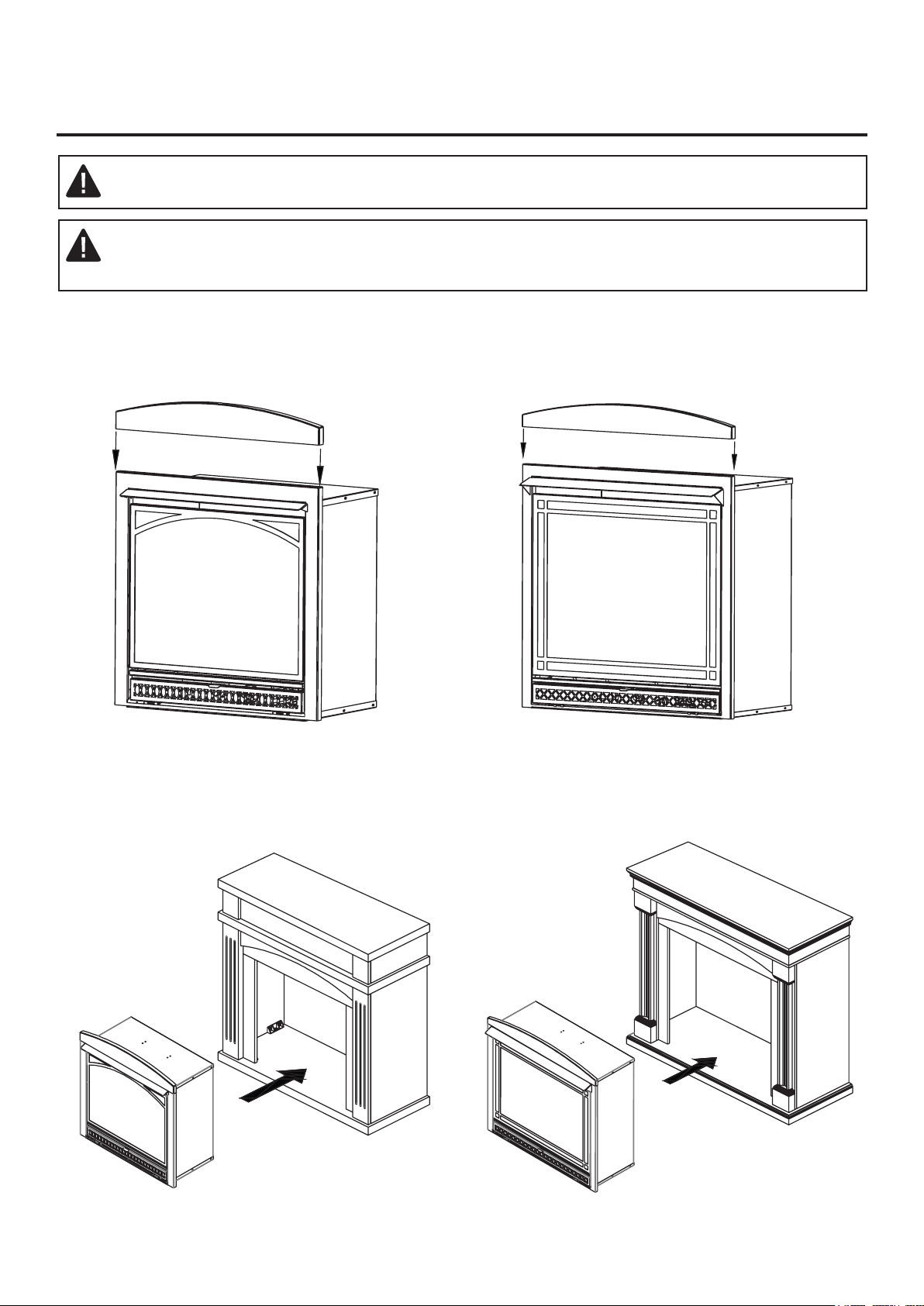
ARCH PANEL ASSEMBLY
WARNING:Alwayshavescreeninplacebeforeoperating�replace.Thisprevents
excessivetemperatureson�replacesurfaces.
WARNING: Failure to position the parts in accordance with these diagrams or failure to
useonlypartsspeci�callyapprovedwiththis�replacemayresultinpropertydamage
or personal injury.
1. Assemblethearchpaneldirectlyontothefrontpanelof�reboxasindicatedinthediagrambelow.
Fig. 2 - Arch Panel Assembly
Carefullylifttheinsertthroughthecenteropeninginthefrontofthe�replace.Slidetheinsertback
through the opening until the metal trim makes contact with the front of the mantel.
VFF-L25D
VFF-L25D
VFF-L32D
VFF-L32D

10
PREPARING FOR INSTALLATION
AIR FOR COMBUSTION AND VENTILATION
WARNING: This heater shall not be installed in a room or space unless the required volume
of indoor combustion air is provided by the method described in the Nation Fuel Gas Code, ANSI
Z223.1/NFPA 54, the International Fuel Gas Code, or applicable local codes.
PRODUCING ADEQUATE VENTILATION
Allspacesinhomesfallintooneofthethreefollowingventilationclassi�cations:
1. Unusually Tight Construction.
2.Uncon�nedSpace.
3.Con�nedSpace.
The information below will help you classify your space and provide adequate ventilation.
Con�nedandUncon�nedSpace
Acon�nedspaceasaspacewhosevolumeislessthan50cu.ft.per1,000BTU/hr(4.8m^3perkw)
oftheaggregateinputratingofallappliancesinstalledinthatspaceandanuncon�ningspaceasa
spacewhosevolumeisnotlessthan50cu.ft.per1,000BTU/hr(4.8m^3perkw)oftheaggregate
input rating of all appliances installed in that space. Rooms connecting directly with the space in
which the appliances are installed*, through openings not furnished with doors, are considered a
partoftheuncon�nedspace.
Thisheatershallnotbeinstalledinacon�nedspaceorunusuallytightconstructionunlessprovisions
are provided for adequate combustion and ventilation air.
* Adjoining rooms are connecting only if there are doorless passageways or ventilation
grills between them.
Unusually Tight Construction
The air that leaks around doors and windows may provide enough fresh air for combustion and venti-
lation. However, in buildings of unusually tight construction, you must provide additional
fresh air.
Unusuallytightconstructionisde�nedasconstructionwhere:
a) walls and ceilings exposed to the outside atmosphere have a continuous water vapor retarder
with a rating of one perm (6x10-11kg per pa-sec-m2) or less with openings gasketed or sealed
and
b) weather stripping has been added on windows that can be opened and on doors and
c) caulking or sealants are applied to areas such as joints around window and door frames,
betweensoleplatesandoors,betweenwall-ceilingjoints,betweenwallpanels,at
penetrations for plumbing, electrical, and gas lines, and at other openings.
If your home meets all of the three criteria above, you must provide additional fresh air.
See “Ventilation Air From Outdoors” (page 12). If your home does not meet all of the
three criteria above, proceed to “Determining Fresh-Air Flow For Heater Location”.

11
PREPARING FOR INSTALLATION
DETERMINING FRESH-AIR FLOW FOR HEATER LOCATION
DeterminingifYouHaveaCon�nedorUncon�nedSpace
Usethisworksheettodetermineifyouhaveacon�nedoruncon�nedspace.
Space: Includes the room in which you will install heater plus any adjoining rooms with
doorless passageways or ventilation grills between the rooms.
1. Determine the volume of the space Length × Width × Height = cu. ft. (volume of space)
Example: Space size 20 ft. (length) × 16 ft.(width) × 8 ft. (ceiling height) = 2560 cu. ft. (volume
of space)
If additional ventilation to adjoining room is supplied with grills or openings, add the volume of these
rooms to the total volume of the space.
2. Divide the space volume by 50 cu. ft. to determine the maximum BTU/hr the space can support.
_______ (volume of space) ÷ 50 cu. ft.= (Maximum BTU/hr the space can support)
Example: 2560 cu. ft. (volume of space) ÷ 50 cu. ft. = 51.2 or 51,200 (maximum BTU/hr the space
can support)
3. Add the BTU/hr of all fuel burning appliances in the space.
Vent-free heater _________ BTU/hr
Gas water heater* ________BTU/hr
Gas furnace _____________BTU/hr
Vented gas heater ________BTU/hr Example:
Gas heater logs __________BTU/hr Gas water heater 30,000 BTU/hr
Other gas appliances*+ ____BTU/hr Vent-free heater + 26,000 BTU/hr
Total = ____BTU/hr Total = 56,000 BTU/hr
*Do not include direct-vent gas appliances. Direct-vent draws combustion air from the
outdoors and vents to the outdoors.
4. Compare the maximum BTU/hr the space can support with the actual amount of BTU/hr used.
_______ BTU/hr (maximum the space can support)
_______ BTU/hr (actual amount of BTU/hr used).
Example : 51,200 BTU/hr (maximum the space can support) 56,000 BTU/hr (actual amount of
BTU/hr used)
Thespaceintheaboveexampleisacon�nedspacebecausetheactualBTU/hrusedismorethan
the maximum BTU/hr the space can support.
You must provide additional fresh air. Your options are as follows:
a) Rework worksheet, adding the space of an adjoining room. If the extra space provides an
uncon�nedspace,removedoortoadjoiningroomoraddventilationgrillsbetweenrooms.See
“Ventilation Air From Inside Building,” page 12.
b) Vent room directly to the outdoors. See “Ventilation Air From Outdoors”, page 12.
c) InstallalowerBTU/hrheateriflowerBTU/hrsizemakesroomuncon�ned.IftheactualBTU/hr
usedislessthanthemaximumBTU/hrthespacecansupport,thespaceisanuncon�nedspace.
You will need no additional fresh air ventilation.
12
PREPARING FOR INSTALLATION
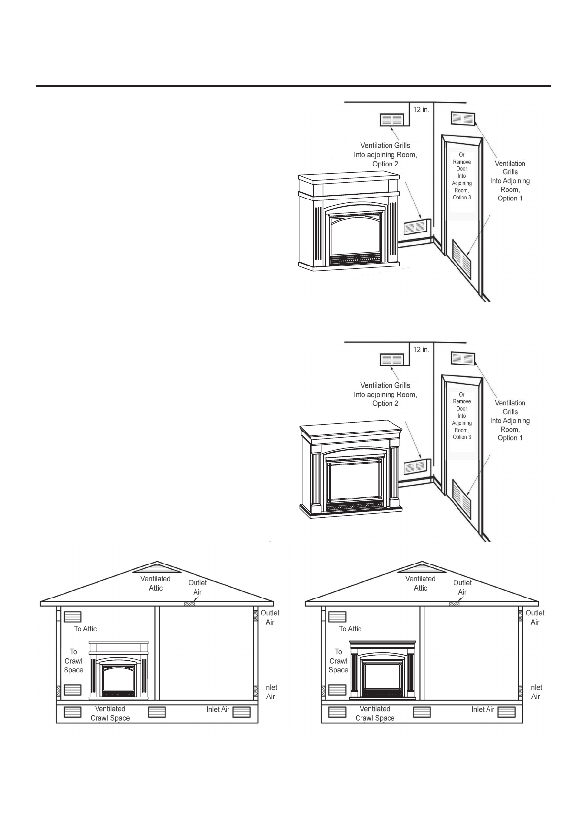
Ventilation Air From Inside Building
Thisfreshairwouldcomefromadjoininguncon�ned
space.Whenventilatingtoanadjoininguncon�ned
space, you must provide two permanent openings:
one within 12 in. of the wall connecting the two spaces
(see options 1 and 2, Fig. 4). You can also remove
door into adjoining room (see option 3, Fig. 4).
Follow the National Fuel Gas Code NFPA 54/ANS
Z223.1. Air for Combustion and Ventilation for
required size of ventilation grills or ducts.
Ventilation Air From Outdoors
Provide extra fresh air by using ventilation grills or
duct. You must provide two permanent openings: one
within 12 in. of the ceiling and one within 12 in. of the
oor.Connecttheseitemsdirectlytotheoutdoorsor
spaces open to the outdoors. These spaces include
attics and crawl spaces.
Follow the National Fuel Gas Code NFPA 54/ANS
Z223.1. Air for Combustion and Ventilation for required
size of ventilation grills or ducts.
IMPORTANT: Do not provide openings for inlet or
outlet air into attic if attic has a thermostat-controlled
power vent. Heated air entering the attic will activate
the power vent. Rework worksheet, adding the space
oftheadjoininguncon�nedspace.Thecombined
spaces must have enough fresh air to supply all
appliances in both spaces.
Fig. 4 - Ventilation Air from
Inside Building
Fig. 5 - Ventilation Air from Outdoors
VFF-L25D
VFF-L25D
VFF-L32D
VFF-L32D

13
INSTALLATION
NOTICE: This heater is intended for use as supplemental heat. Use this heater along with your
primary heating system. Do not install this heater as your primary heat source.
WARNING:Aquali�edtechnicianmustinstallheater.Followalllocalcodes.
WARNING: Never install the heater:
• In a bedroom or bathroom.
• In a recreational vehicle.
• Wherecurtains,furniture,clothing,orotherammableobjectsarelessthan42in.fromthe
front, top or sides of the heater.
• Inhightraf�careas.
• In windy or drafty areas.
WARNING: Maintain the minimum clearances. If possible, provide greater clearances from the
oor,ceiling,andadjoiningwallthanrequired.
CAUTION: This heater creates warm air currents. These currents move heat to wall surfaces next
to heater. Installing heater next to vinyl or cloth wall coverings or operating heater where impurities
(suchastobaccosmoke,aromaticcandles,cleaninguids,oilorkerosenelamps,etc.)intheair
exist, may cause walls to discolor.
IMPORTANT: Vent-freeheatersaddmoisturetotheair.Althoughthisisbene�cial,installingheaterin
rooms without enough ventilation air may cause mildew to form from too much moisture. See Air for
Combustion and Ventilation, pages 10 through 12.
CHECK GAS TYPE
Be sure your gas supply is right for your heater.
CLEARANCES TO COMBUSTIBLES
Carefully follow the instructions below. This heater is a designed to sit directly on the mantel base.
IMPORTANT: Maintain the minimum clearances shown in Figure 6 on page 14. If you can, provide
greaterclearancesfromoor,ceilingandjoiningwall.
14
INSTALLATION
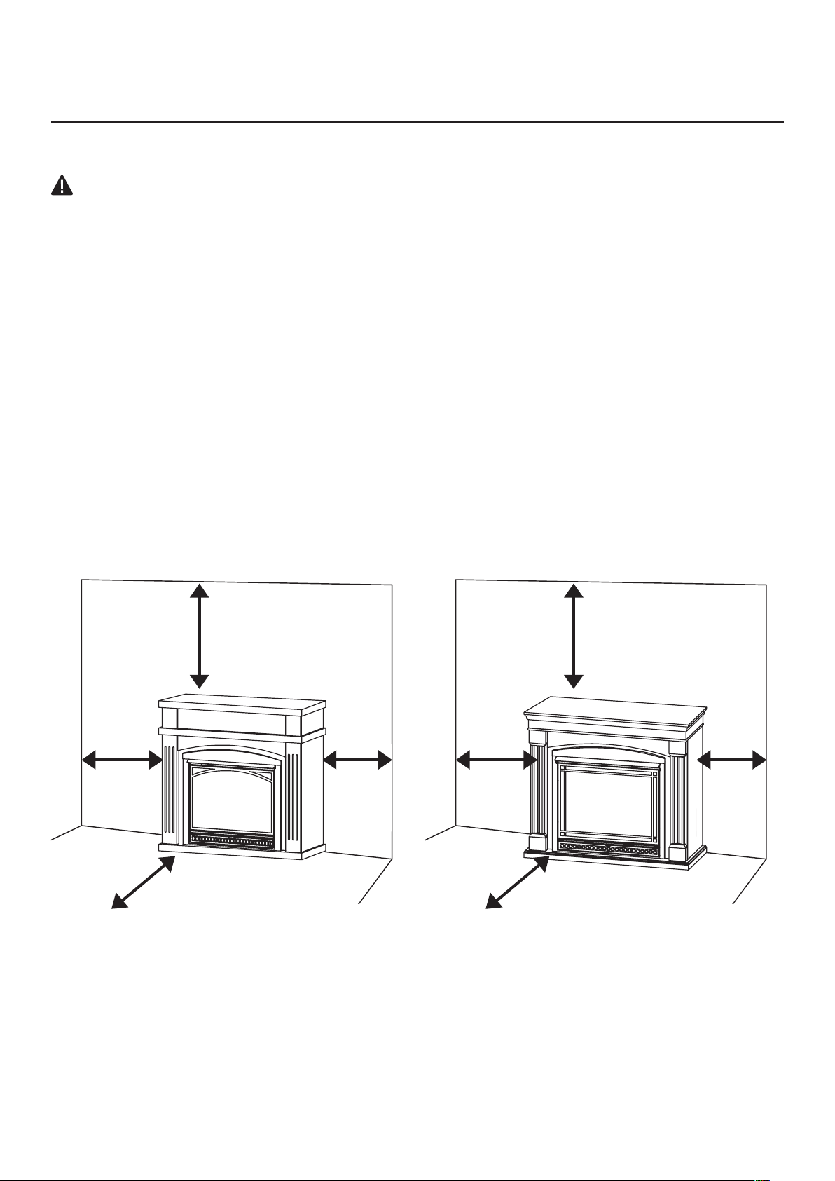
FIREPLACE CLEARANCES
CAUTION:Ifyouinstallthe�replaceinahomegarage
•Fireplacepilotandburnermustbeatleast18"aboveoor.
•Locate�replacewheremovingvehiclewillnothitit.
Forconvenienceandef�ciency,install�replace
• Where there is easy access for operation, inspection and service.
• In coldest part of room.
• If this appliance is to be installed directly on carpeting, tile or other combustible material, other than
woodooring,theappliancemustbeinstalledonametalorwoodpanelextendingthefullwidth
and depth of the appliance.
Minimum Clearances For Side Combustible Material, Side Wall and Ceiling
A.Clearancesfromthesideofthe�replacecabinettoanycombustiblematerialandwallshould
follow diagram in Figure 6.
B.Clearancesfromthetopofthe�replaceopeningtotheceilingshouldnotbelessthan36".
6’’
Either
Side
Min.
36’’
6’’
Either
Side
Min.
36’’
Fig. 6 - Minimum Clearance to
Combustible Material
Min.
36''
Min.
36''
36'' 36''
6''
Either
Side
6''
Either
Side
6'' 6''
•This�reboxisonlyforusewiththemantelprovided.
VFF-L25D VFF-L32D
15
INSTALLATION
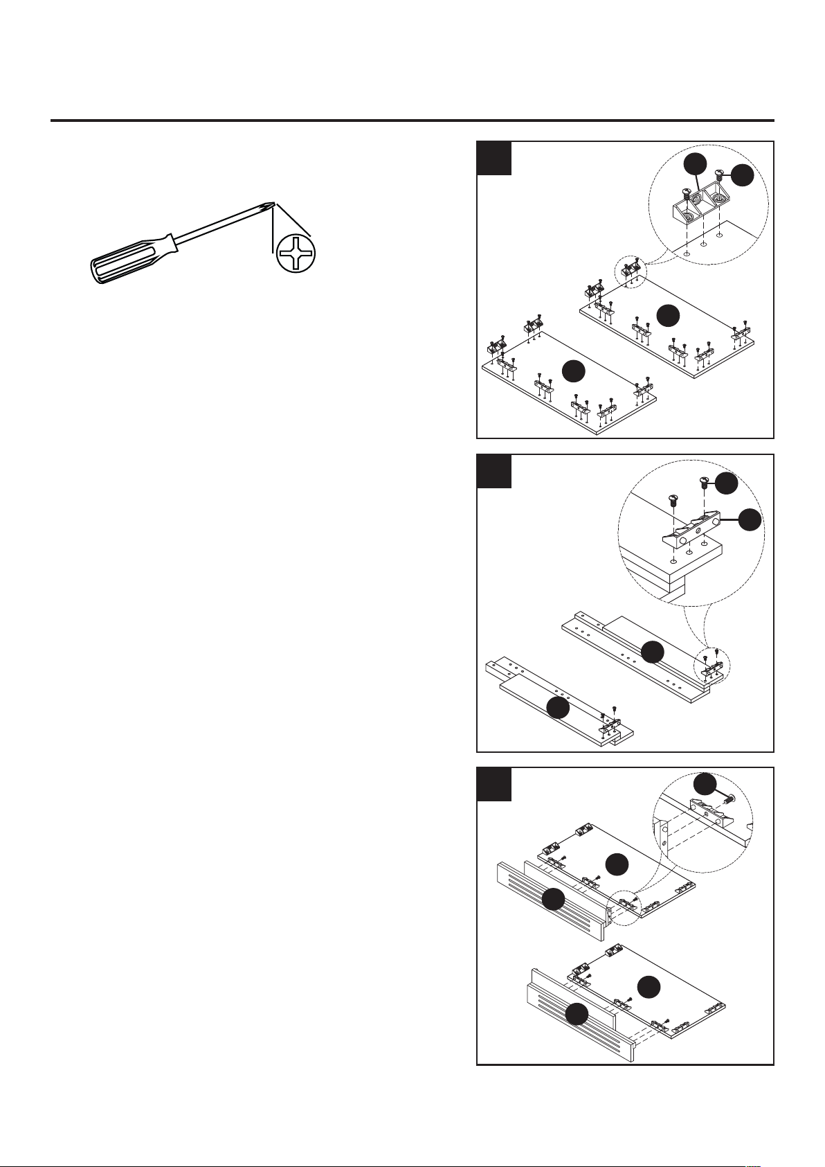
Tools Required:
• Phillips screwdriver (not included)
1. Secure connectors (AA) to left (C) and right (D)
side panels using short bolt (BB).
2. Secure connectors (AA) to left (E) and right (F)
front panels using short bolt (BB).
3. Connect left front panel (E) to left side panel (C)
with short bolt (BB).
Connect right front panel (F) to right side panel
(D) with short bolt (BB).
VFF-L25D MANTEL ASSEMBLY
3
2
1
D
D
F
F
C
C
E
E
BB
BB
AA
AA
BB

16
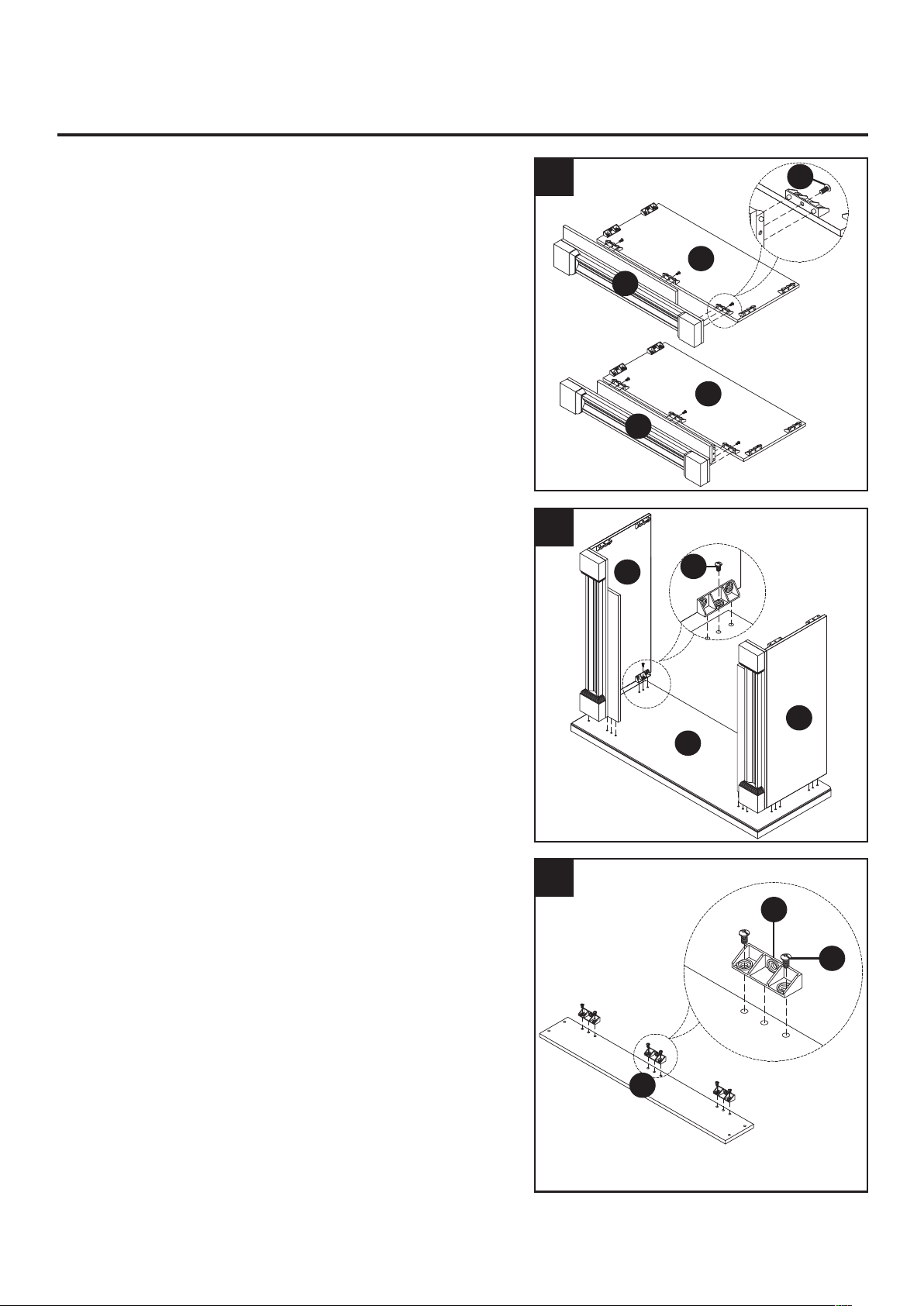
INSTALLATION
4. Connect left (C) and right (D) side panels to
base (B) using short bolts (BB).
5. Secure connectors (AA) to upper front panel (G)
using short bolt (BB).
6. Connect upper front panel to left (E) and
right (F) front panels using the long bolts (CC)
and washers (DD).
6
5
4
C
D
B
BB
G
BB
DD
G
AA
CC

17
INSTALLATION
7. Connect top panel (A) to the left (C) and right (D)
side panel using the short bolts (BB).
7
BB
BB
BB
AA
AA
D
F
C
E
A
Tools Required:
• Phillips screwdriver (not included)
1. Secure connectors (AA) to left (C) and right (D)
side panels using short bolt (BB).
2. Secure connectors (AA) to left (E) and right (F)
front panels using short bolt (BB).
VFF-L32D MANTEL ASSEMBLY
1
2
18
INSTALLATION
3. Connect left front panel (E) to left side panel (C)
with short bolt (BB).
Connect right front panel (F) to right side panel
(D) with short bolt (BB).
4. Connect left (C) and right (D) side panels to
base (B) using short bolts (BB).
5. Secure connectors (AA) to upper front panel (G)
using short bolt (BB).
5
4
3
F
E
C
D
BB
BB
BB
AA
G
C
D
B

19
INSTALLATION
6. Connect upper front panel to left (E) and right (F)
front panels using the long bolts (CC) and
washers (DD).
7. Connect top panel (A) to the left (C) and right (D)
side panel using the short bolts (BB).
7
6
DD
DD
G
CC
20
GAS SELECTION INSTRUCTIONS
CAUTION: The knob to the gas selection means shall not be accessed or adjusted while the
appliance is in operation.
CAUTION: Two gas line installations at the same time are prohibited. The access plate to simple
switching means shall not be opened while heater is in operation.
Installationandadjustmentsshallbemadebyaquali�edtechnicianonly.
NOTE: If you are connecting this appliance to propane do not make any adjustments. Proceed to
installing the gas line as instructed in the Owner’s Manual.
Convert to natural gas:
Step 1 - Adjust the gas selector valve
Push in on the selector valve Knob and rotate the knob
counter-clockwise until it stops. Release the knob (See Fig. 8)
Do not operate the appliance between locked positions.
Reverse step 1 to convert back to propane gas.
INSTALLATION
WARNING: This appliance can be used with propane or natural gas. It is shipped from the
factory adjusted for use with propane.
LP
NG
LP
NG
Fig. 8 - Selector Valve
Propane
Position
Natural Gas
Position

21
CONNECTING TO GAS SUPPLY
WARNING:Aquali�edservicetechnicianmustconnectheatertogassupply.Followalllocal
codes.
CAUTION: Never connect heater directly to the gas supply. This heater requires an external
regulator (not supplied). The external regulator between the gas supply and heater must be installed.
Gas supplier provides external regulator for natural gas.
WARNING: Never connect heater to private (non-utility) gas wells. This gas is commonly known
as wellhead gas.
The installer must supply an external regulator for liquid propane. The external regulator is provided
by the gas supplier for natural gas. The external regulator will reduce incoming gas pressure. You
must reduce incoming gas pressure to between 11 and 14 in. of water column for propane and
between 6 and 14 in. of water column for natural gas. If you do not reduce incoming gas pressure,
heater regulator damage could occur. Install external regulator with the vent pointing down as shown
in Fig. 6. Pointing the vent down protects it from freezing rain or sleet.
* Purchase the optional equipment shutoff valve from your local Home Center store.
INSTALLATION
CAUTION: Use only new black iron or steel pipe. Internally tinned copper tubing
may be used in certain areas. Check your local codes. Use pipe of ½ in. diameter
or greater to allow proper volume gas to heater. If pipe is too small, loss of pressure
will occur. Installation must include an equipment shutoff valve, union, and plugged
1/8-in. NPT tap. Locate NPT tap within reach for test gauge hook up. NPT tap must
be upstream from heater (See Fig. 10).
IMPORTANT: Install equipment shutoff valve in an accessible location. The equipment
shutoff valve is for turning on or shutting off the gas to the appliance. Apply pipe joint
sealant lightly to male threads. This will prevent excess sealant from going into pipe.
Excess sealant in pipe could result in clogged heater valves.
Approved
Flexible
Gas Line
or 1/2''
Black Pipe
Fig. 9 - Regulator Conversion
Fig. 10 - Gas Connection
6
14
22
INSTALLATION
Fig. 11 - Attaching Flexible Gas Line
to Equipment Shutoff Valve
Flexible Gas Line
or Black Pipe to
Fireplace Cabinet
Regulator
To Regulator
NOTICE: Most building codes do not permit concealed gas connections. Check
your local building code prior to using a Flexible Gas Line for this installation.
CAUTION: Use pipe joint sealant that is resistant to gas (PROPANE or NG). We
recommend that you install a sediment trap in a supply line as shown in Fig. 10.
Locate sediment trap where it is within reach for cleaning and not likely to freeze.
Install in the piping system between fuel supply and heater. A sediment trap traps
moisture and contaminants. This keeps them from going into heater controls. If
sediment trap is not installed or is installed incorrectly, heater may not run properly.
CAUTION: Avoid damage to regulator. Hold gas regulator with wrench when
connectingintogaspipingand/or�ttings.NGModels:6in.to14in.W.C.Gas
supplier provides external regulator for natural gas.
• 8'' Adjustable Wrench
• 8'' Pipe Wrench
• Flexible Gas Line (24'' Min.) or 1/2'' Black Pipe
• 90 Deg. 3/8 NPT x 3/8'' Flare Fitting or 3/8'' Street Elbow
• Sealant (Resistant to Propane (LP) Gas)
• Shut Off Valve
1) A variety of options are possible for routing the Gas Connection Lines depending on where
your Gas Supply line is located. Install the 3/8'' Fitting to the Fireplace Cabinet Regulator
using Sealant and direct the attachment and either left or right toward the Gas Supply Line.
InstallationItemsNeeded(NotProvided)
2)InstalltheGasLinetothe90Deg.�ttingandattachtotheShutOffValve.Itmaybe
necessary to cut and access hole in the side or bottom of the Mantel Cabinet depending on
your particular connection.
3) Check all connections for gas leaks.
LP Regulator
LP Regulator
NG Regulator
NG Regulator
VFF-L25D VFF-L32D

23
VFF-L25D
WARNING:
Failure to position the parts in accordance with these diagrams or failure to use only parts
speci�callyapprovedwiththisheatermayresultinpropertydamageorpersonalinjury.
CAUTION:
Afterinstallationandperiodicallythereafter,checktoensurethatnoyellowamecomesin
contactwithanylog.WiththeheatersettoHigh,checktoseeifyellowamescontactanylog.Ifso,
repositionlogsaccordingtotheloginstallationinstructionsinthismanual.Yellowamescontacting
logs will create soot.
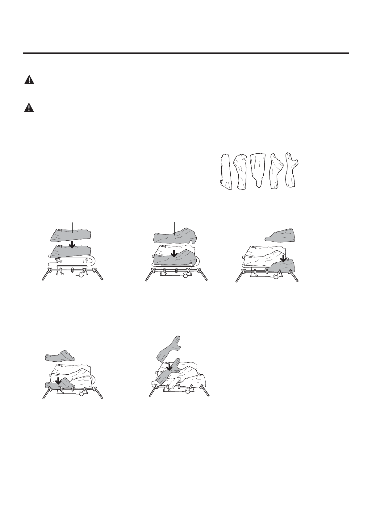
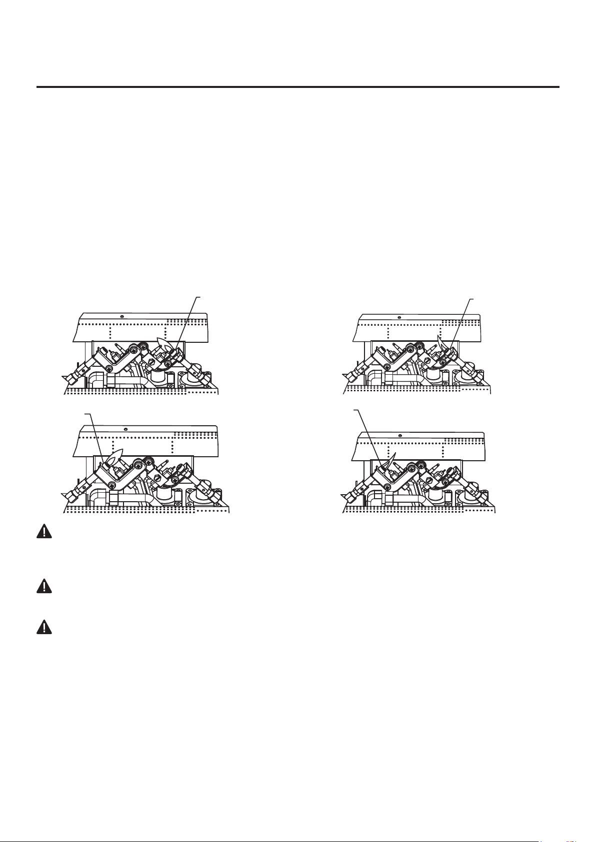
It is very important to install the logs
exactly as instructed. Do not modify logs.
Use only logs supplied with heater.
Each log is marked with a number.
this number will help you identify the logs
when installing.
Provided Logs: 5
Installing Log #1 Installing Log #2 Installing Log #3
2
1
3
1. Insert log #1 onto the
rear row of pins on the
base pan.
2. Insert log #2 onto the
front left pin on the base
pan.
3. Insert log #3 onto the
front right pin on the base
pan.
Installing Log #4 Installing Log #5
4
5
4. Insert log #4 onto the left
pin of log #1 and the pin of
log #2.
5. Insert log #5 onto the
right pin of log #1 and the
pin of log #3.
1
2 3 4 5
ASSEMBLING LOGS
24
VFF-L32D
WARNING:
Failure to position the parts in accordance with these diagrams or failure to use only parts
speci�callyapprovedwiththisheatermayresultinpropertydamageorpersonalinjury.
CAUTION:
Afterinstallationandperiodicallythereafter,checktoensurethatnoyellowamecomesin
contactwithanylog.WiththeheatersettoHigh,checktoseeifyellowamescontactanylog.Ifso,
repositionlogsaccordingtotheloginstallationinstructionsinthismanual.Yellowamescontacting
logs will create soot.
It is very important to install the logs
exactly as instructed. Do not modify logs.
Use only logs supplied with heater.
Each log is marked with a number.
this number will help you identify the logs
when installing. After installing logs, add
decorative cinders around the grate base,
do not place any decorative cinders on
logs or burner.
Provided Logs: 5
Installing Log #1 Installing Log #2 Installing Log #3
2
1
4
1. Insert log #1 onto the
rear brackets of the base
pan.
2. Insert log #2 onto the
middle row of pins on the
base pan.
4. Insert log #4 onto the
front left pin of the base
pan.
Installing Log #4 Installing Log #5
3
5
3. Insert log #3 onto the
front right pin of the base
pan.
5. Insert log #5 onto the
left pins of log #1 & #2 and
the pin of log #3.
ASSEMBLING LOGS
4
3
541 2 3
25
INSTALLATION
CHECKING GAS CONNECTIONS
WARNING: Test all gas piping and connections for leaks after installing or servicing. Correct all
leaks immediately.
WARNING:Neveruseanopenametocheckforaleak.Applyamixtureofliquidsoapandwater
to all joints. If bubbles form, there may be a leak. Correct all leaks immediately.
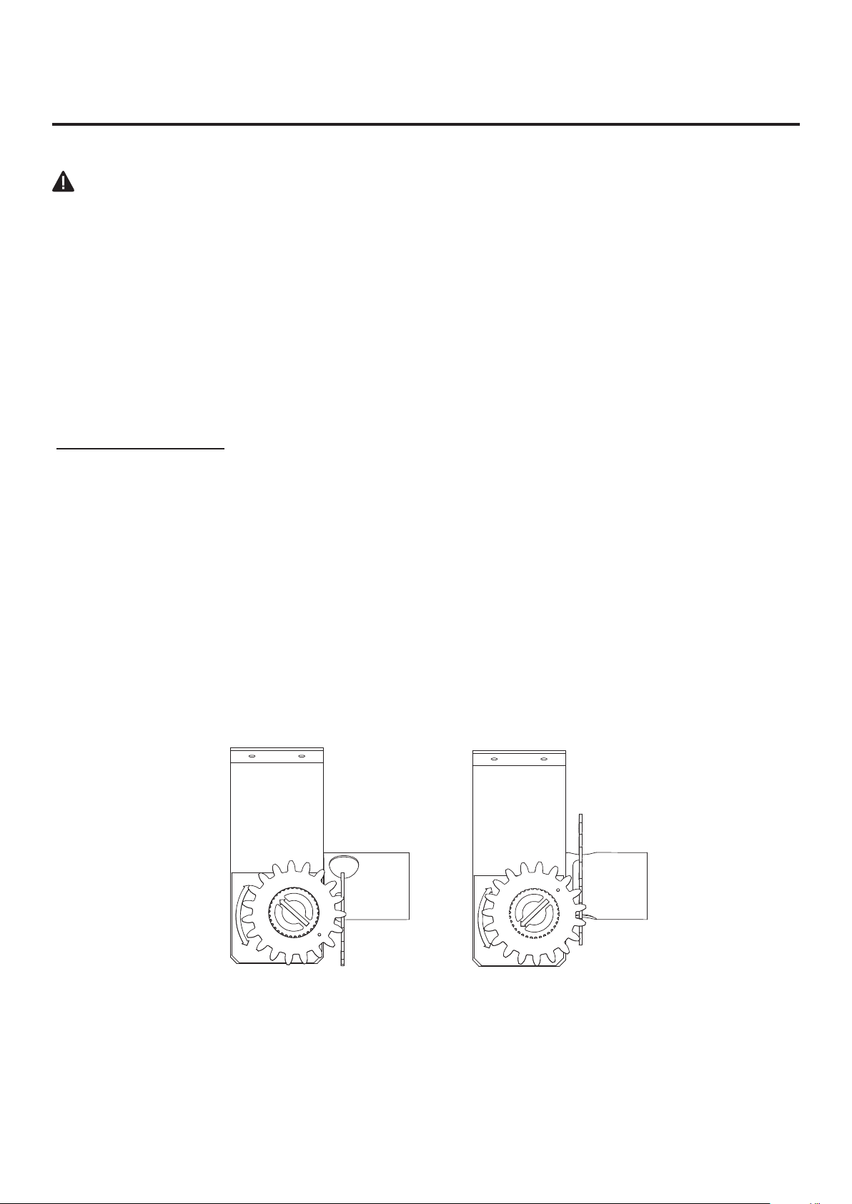
Pressure Testing Gas Supply Piping System
TestPressuresInExcessOf1/2PSIG(3.5kPa)
1. Disconnect heater with its appliance main gas valve (control valve) and equipment shutoff valve
from gas supply piping system. Pressures in excess of 1/2 PSIG will damage heater regulator.
2. Cap off open end of gas pipe where equipment shutoff valve was connected.
3. Pressurize supply piping system by either using compressed air or opening gas supply tank valve.
4. Check all joints of gas supply piping system. Apply mixture of liquid soap and water to gas joints. If
bubbles form, there may be a leak.
5. Correct all leaks immediately.
6.Reconnectheaterandequipmentshutoffvalvetogassupply.Checkreconnected�ttingsforleaks.
TestPressuresEqualToorLessThan1/2PSIG(3.5kPa)
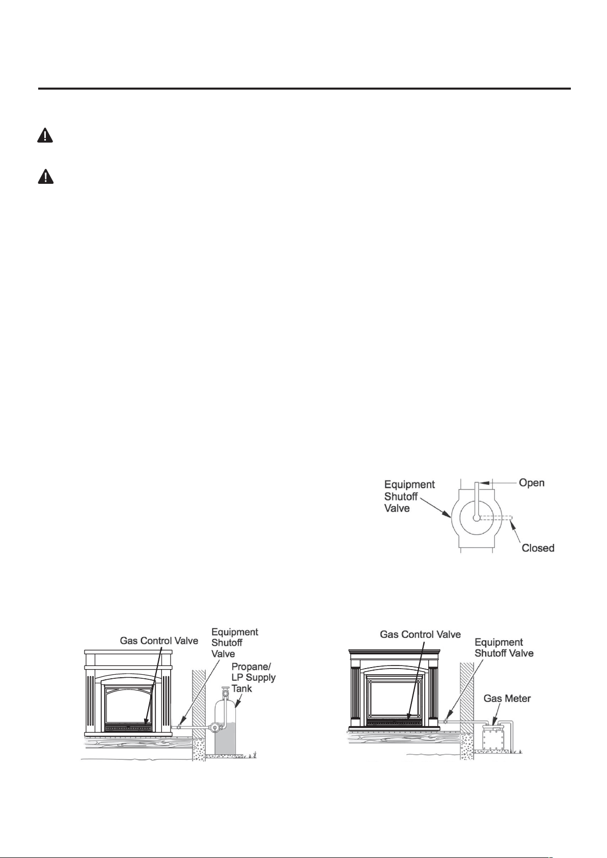
1. Close equipment shutoff valve (See Fig. 12).
2. Pressure supply piping system by either using compressed air or opening gas supply tank valve.
3. Check all joints from gas meter to equipment shutoff valve (See Fig.13). Apply mixture of liquid
soap and water to gas joints. If bubbles form, there may be a leak.
4. Correct all leaks immediately.
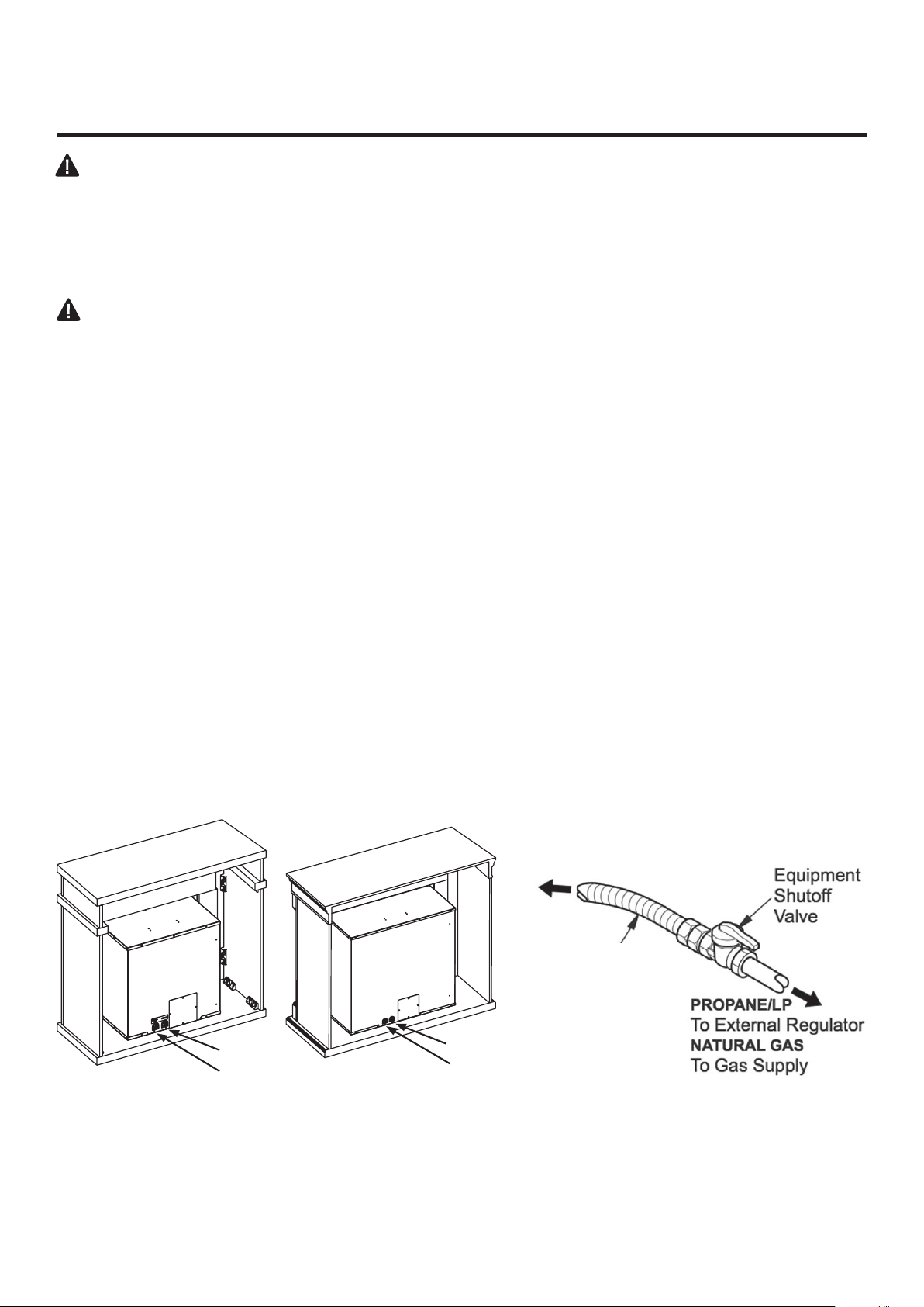
Pressure Testing Heater Gas Connections
1. Open equipment shutoff valve (See Fig. 12).
2. Open gas supply tank valve.
3. Make sure control knob of heater is in the OFF position.
4. Check all joints from equipment shutoff valve to control valve
(See Fig. 13). Apply mixture of liquid soap and water to gas joints.
If bubbles form, there may be a leak.
5. Light heater (see Operation, page 26).
Check all other internal joints for leaks.
6. Turn off heater (see "To Turn Off Gas to Appliance," page 27).
Fig. 13 - Checking Gas Joints
(Propane/LP Only)
Fig. 12 - Equipment Shutoff Valve
Fig. 14 - Checking Gas Joints
(Natural Gas Only)
26
FOR YOUR SAFETY; READ BEFORE LIGHTING
LIGHTING INSTRUCTIONS
OPERATION
WARNING:Ifyoudonotfollowtheseinstructionsexactly,a�reorexplosionmay
result causing property damage, personal injury or loss of life.
A. This appliance has a pilot which must be lighted by the electronic ignitor. When lighting the pilot,
follow these instructions exactly.
B. BEFORE LIGHTINGsmellallaroundtheapplianceareaforgas.Besuretosmellnexttotheoor
becausesomegasisheavierthanairandwillsettleontheoor.
WHAT TO DO IF YOU SMELL GAS
• Do not try to light any appliance.
• Do not touch any electrical switch; do not use any phone in your building.
• Immediately call your gas supplier from a neighbor’s phone. Follow the gas supplier’s instructions.
•Ifyoucannotreachyourgassupplier,callthe�redepartment.
C. Use only your hand to push in or turn the gas control knob. Never use tools. If the knob will not
pushinorturnbyhand,don’ttrytorepairit,callaquali�edservicetechnician.Forcedorattempted
repairmayresultin�reorexplosion.
D.Donotusethisapplianceifanyparthasbeenunderwater.Immediatelycallaquali�edservice
technician to inspect the appliance and to replace any part of the control system and any gas control
which has been under water.
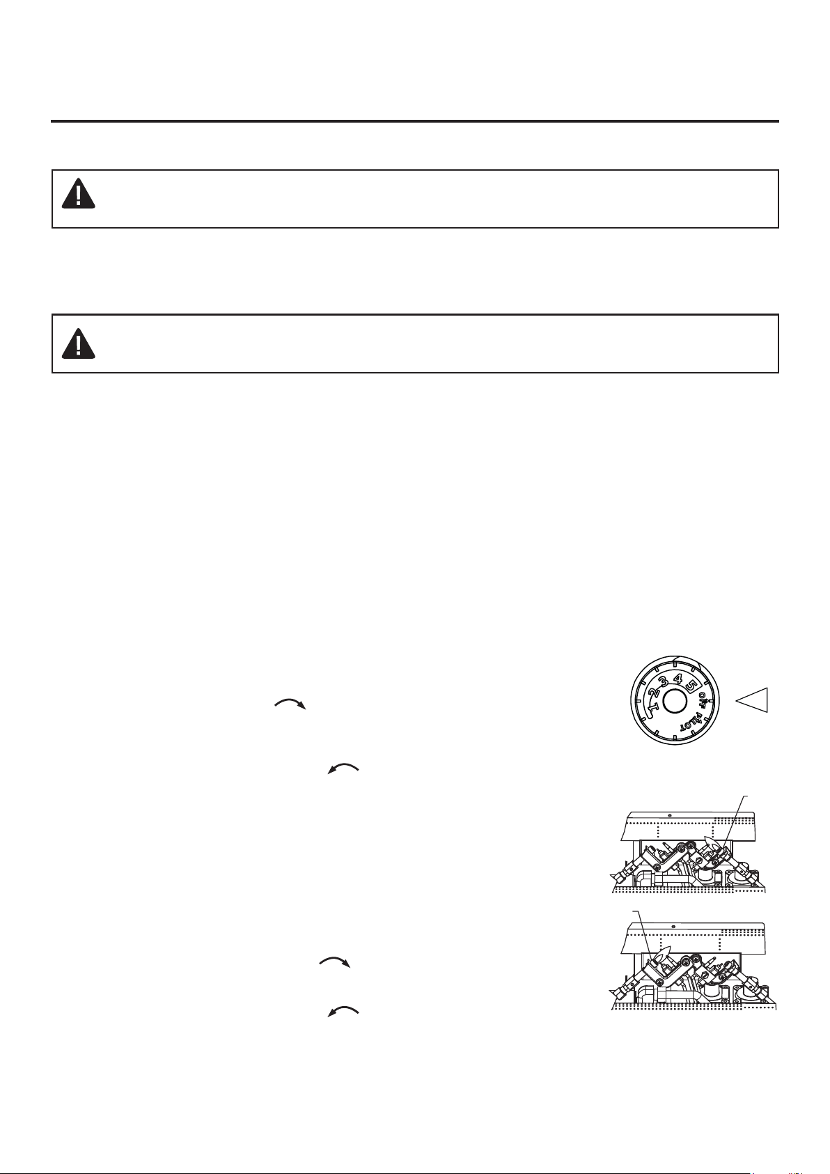
1. STOP! Read the safety information as noted above.
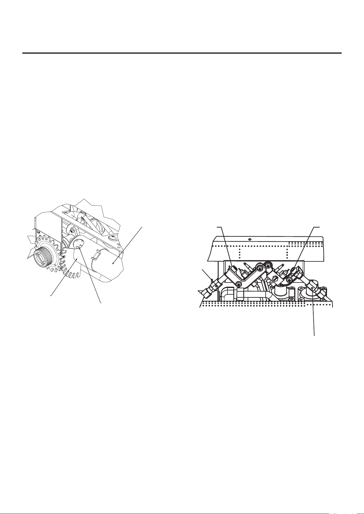
2.Opentheloweraccesspanellocatedbelowthe�replacescreen.
3. Turn control knob clockwise to the “OFF” position (See Fig. 15).
4.Wait�ve(5)minutestoclearoutanygas.Thensmellforgas,including
neartheoor.Ifyousmellgas,STOP!Follow“B”inthesafetyinforma-
tion as noted above. If you don’t smell gas, go to the next step.
5. Turn control knob counterclockwise to the “PILOT” position (See
Fig. 16). Depress control knob.
6. With control knob depressed, push down on the ignitor button until the
pilotlights.Thepilotislocatedbehindthe�replacescreen,centered
near the rear of the burner.
7. Keep control knob depressed for (30) seconds after pilot lights. Release
control knob.
• If the control knob does not pop up when released, stop and immediately
callaquali�edservicetechnicianorgassupplier.
• If pilot goes out repeat steps 3 through 7. Wait (1) minute before
attempting to light pilot again. If after several tries the pilot still goes out,
turn the gas control knob clockwise to the “OFF” position and call a
quali�edservicetechnician.
8. Turn control knob counterclockwise to desired setting.
9. Close lower access panel.
Fig. 15 - Control Knob
Fig. 16 - Pilot
Model VFF-L25D
LP PILOT
NG PILOT
WARNING: Do not use a blower insert, heat exchanger insert or other accessory not
approved for use with this heater.

27
OPERATION
Model VFF-L32D
1. STOP! Read the safety information on the page before this.
2.Opentheloweraccesspanellocatedbelowthe�replacescreen.
• Set receiver switch to “ON” position (See Fig. 17).
3. Turn control knob clockwise to the “OFF” position (See Fig. 17).
4.Wait�ve(5)minutestoclearoutanygas.Thensmellforgas,including
neartheoor.Ifyousmellgas,STOP!Follow“B”inthesafetyinformation
on the page before this. If you don’t smell gas, go to the next step.
5. Push in slightly and turn control knob counterclockwise to the
“PILOT” position (See Fig. 17). Depress control knob.
6. With control knob depressed, push down on the ignitor button until the
pilotlights.Thepilotislocatedbehindthe�replacescreen,centerednear
the rear of the burner (See Fig. 18).
7. Keep control knob depressed for (30) seconds after pilot lights. Release
control knob.
• If the control knob does not pop up when released, stop and immediately
callaquali�edservicetechnicianorgassupplier.
• If pilot goes out repeat steps 3 through 7. Wait (1) minute before attempting
to light pilot again. If after several tries the pilot still goes out, turn the
gascontrolknobclockwisetothe“OFF”positionandcallaquali�ed
service technician.
8. Turn control knob counterclockwise to the “ON” position.
9. To use the included thermostatic remote control, set receiver switch to
the “REMOTE” position (See Fig. 19). Press the ON button to turn on the
remote to ignite the main burner. Refer to the remote control instruction
manual on the next page for “MODE” and “SET” functions.
ONOFF
REMOTE
LEARN
Model VFF-L25D
1.Opentheloweraccesspanellocatedunderthe�replacescreen.
2. Turn control knob clockwise to the “OFF” position.
3. Close lower access panel.
Model VFF-L32D
1. Set thermostat to the lowest setting.
2. Press the OFF button on the remote control.
3.Opentheloweraccesspanellocatedunderthe�replacescreen.
4. Push in slightly and turn control knob clockwise to the “OFF” position.
5. Close lower access panel.
Fig. 17 - Receiver
& Control Knob
ON
OFF
MODE
SET
Fig.19 - Remote
Fig. 18 - Pilot
LP PILOT
NG PILOT
TO TURN OFF GAS TO APPLIANCE

28
REMOTE CONTROL OPERATION
MULTI-FUNCTIONWIRELESSREMOTECONTROLSYSTEM
FOROPERATINGALATCHINGSOLENOIDVALVE,MANUALLYORWITHATHERMOSTATFUCTION
INTRODUCTION
This remote control system was developed to provide a safe, reliable, and user-friendly remote control system for gas heating
appliances. Thesystemisoperatedmanually fromthetransmitter. Thesystemoperateson radiofrequencies (RF)withina 20-feet
rangeusingnon-directionalsignals.Thesystemoperatesononeof1,048,576securitycodesthatareprogrammedintothetransmitter
atthefactory;theremotereceiver'scodemustbematchedtothatofthetransmitterpriortoinitialuse.
ReviewCOMMUNICATIONSAFETYunderGENERALINFORMATIONsection.Thissafetyfeatureshutsdown
theappliancewhenapotentiallyunsafeconditionexists.
TRANSMITTER
ThisremotecontrolSYSTEMofferstheuserabattery-operatedremotecontrolto
power a latching solenoid such as those used with gas valves used in some
heaterratedgaslogs,gasfireplacesandothergasheatingappliances.
The solenoid circuit uses the battery power from the receiver to operate a
solenoid.Thecircuithasreversingpolaritysoftwarewhichreversesthepositive
(+) and negative (-) output of the receiver's battery power to drive a latching
solenoidON/OFF.TheSYSTEMiscontrolledbytheremotetransmitter.
Thetransmitteroperatesona(2)1.5VAAAbatteries.
ALKALINEbatteriesshouldalwaysbeusedforlongerbatterylifeandmaximum
operationalperformance.Re-chargeablebatteriesshouldnotbeused.
Before using the transmitter, install the (2) AAA transmitter batteries into the
battery compartment. (Use caution that batteries are installed in the proper
direction)
KEYSETTINGS
ON-Operatesunittoonposition,ManuallyoperatedsolenoidON.
OFF-Operatesunittooffposition,ManuallyoperatedsolenoidOFF.
MODE-Changesunitfrommanualmodetothermomode.
SET-Setstemperatureinthermomode.
ON
MODE
OFF
SET
1
2
3
4
ON
MODE
OFF
BUTTON
WALL CLIP
SLOT
BATTERY
COMPARTMENT
FRONT BACK
OFF
SET
ON
BUTTON
MODE
BUTTON
SET
BUTTON
IF YOU CANNOT READ OR UNDERSTAND THESE INSTALLATION
INSTRUCTIONS DO NOT ATTEMPT TO INSTALL OR OPERATE
Review COMMUNICATION SAFETY under GENERAL INFORMATION section. This
safety feature shuts down the appliance when a potentially unsafe condition exists.
29
REMOTE CONTROL OPERATION
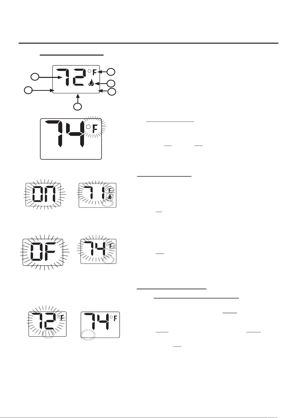
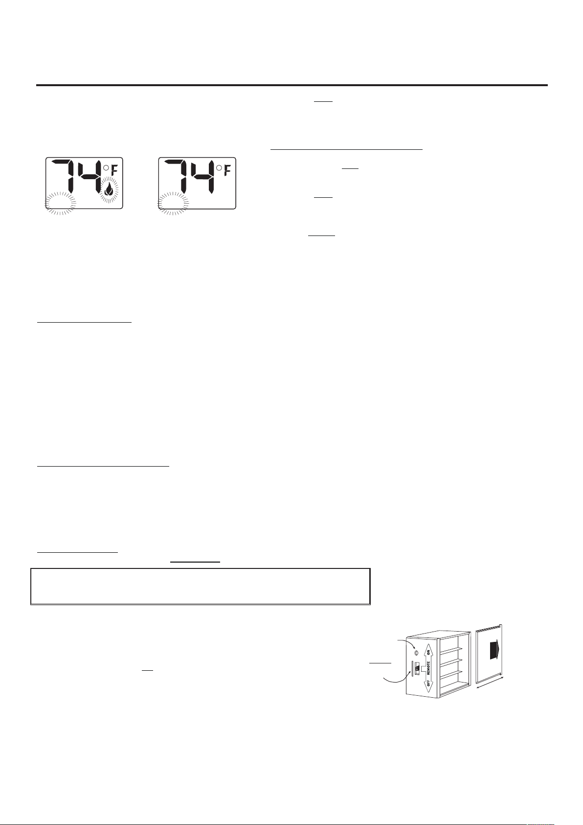
1. DISPLAY IndicatesCURRENTroomtemperature.
2.
0
FOR
0
C IndicatesdegreesFahrenheitorCelsius.
3. FLAME Indicatesburner/valveinoperation.
4. ROOM IndicatesremoteisinTHERMOoperation.
5. TEMP Appearsduringmanualoperation.
6. SET Appearsduringtimetheofsettingthedesired
temperatureinthethermooperation.
SETTING
0
F/
0
CSCALE
Thefactorysettingfortemperatureis
0
F.Tochangethissettingto
0
C,
first
¥ PresstheONkeyandtheOFFkeyonthetransmitteratthesame
timethiswillchangefrom
0F
to
0C
.Followthissameprocedureto
changefrom
0
Cbackto
0
F.
MANUALFUNCTION
Tooperatethesysteminthemanual“MODE”dothefollowing.
ONOPERATION
PresstheONkeytheapplianceflamewillcomeon.Duringthistimethe
LCDscreenwillshowON,after3secondstheLCDscreenwilldefault
todisplayroomtemperatureandthewordTEMPwillshow.(Flameicon
willappearonLCDscreeninmanualonmode)
OFFOPERATION
PresstheOFFkeytheapplianceflamewillshutoff.Duringthistimethe
LCDscreenwillshowOF,after3secondstheLCDscreenwilldefaultto
displayroomtemperatureandthewordTEMPwillshow.
THERMOSTATFUNCTION
SETTINGDESIREDROOMTEMPERATURE
Thisremotecontrolsystemcanbethermostaticallycontrolledwhenthe
transmitterisintheTHERMOmode(ThewordROOMmustbe
displayedonthescreen).TosettheTHERMOMODEandDESIRED
roomtemperature,
PresstheMODEkeyuntiltheLCDscreenshowsthewordROOM,
thentheremoteisinthethermostaticmode.
PressandholdtheSETkeyuntilthedesiredsettemperatureis
reached.(BypressingandholdingthesetkeytheLCDscreenset
numberswillincreasefrom45
0
to99
0
thenrestartoverat45
0
)Next
TEMP
TEMPSET
THERMOSET
SCREENWHILE
DEPRESSINGOFF
KEY
TEMP
SCREENAFTER3
SECONDDEFAULT
ROOM
TEMP
TH
ERMOMODE
TEMP
SCREENAFTER3
SECONDDEFAULT
ROOM
LCD - Liquid Crystal Display
TEMP
1
2
3
SET
4
5
6
SCREENWHILE
DEPRESSINGON
KEY
30
REMOTE CONTROL OPERATION
releasetheSETkey.TheLCDscreenwilldisplaythesettemperature
for3secondsandtheLCDscreenwillflashthesettemperaturefor3
seconds,thentheLCDscreenwilldefaulttodisplaytheroom
temperature.
TOCHANGETHESETTEMPERATURE
PressandholdtheSETkeyuntilthedesiredsettemperatureis
reached.(BypressingandholdingthesetkeytheLCDscreenset
numberswillincreasefrom45
0
to99
0
thenrestartoverat45
0
)Next
releasetheSETkey.TheLCDscreenwilldisplaythesettemperature
for3seconds,thenwillflashthesettemperaturefor3seconds,thenthe
LCDscreenwilldefaulttodisplaytheroomtemperature.
PresstheMODEkeytodisengagethethermomode.ThewordROOM
ontheLCDscreenwillnotshowwhenthethermoisnotinoperation.
NOTE:ThehighestSETtemperatureis99
0
Fahrenheit(32
0
Celsius)
andthelowesttemperatureis(45
0
Fahrenheit(6
0
Celsius)
OPERATIONALNOTES:
TheThermoFeatureonthetransmitteroperatestheappliancewhenevertheROOMTEMPERATUREvariesacertainnumberof
degreesfromtheSETTEMPERATURE.Thisvariationiscalledthe“SWING”orTEMPERATUREDIFFERENTIAL.Thenormal
operatingcycleofanappliancemaybe2-4timesperhourdependingonhowwelltheroomorhomeisinsulatedfromthecoldordrafts.
Thefactorysettingforthe“swingnumber”is2.Thisrepresentsatemperaturevariationof+/-2
0
F(1
0
C)betweenSETtemperature
andROOMtemperature,whichdetermineswhenthefireplacewillbeactivated.
ThetransmitterhasONandOFFmanualfunctionsthatareactivatedbypressingeitherbuttononthefaceofthetransmitter.Whena
buttononthetransmitterispressedthewordONorOFwillappearontheLCDscreentoshowwhilethesignalisbeingsent.Upon
initialuse,theremaybeadelayofthreesecondsbeforetheremotereceiverwillrespondtothetransmitter.Thisispartofthesystem's
design.
POWERSETTING–CON1001TH
Theelectronics intheremotecontrolsystemhavethecapabilityof"powering"twodifferenttypesofDC-poweredcomponents.Ifany
operationalproblemsarenoted,contactCustomerService.
TheRECEIVERcomesfromthefactoryprogrammedtoprovidepulseDCvoltage(5.5VDCto6.3VDC)toalatchingsolenoid.
REMOTERECEIVER
IMPORTANT
THEREMOTERECEIVERSHOULDBEPOSITIONEDWHEREAMBIENT
TEMPERATURESDONOTEXCEED130°F.
The remote receiver (right) operates on (4) 1.5V AA-size batteries. It is
recommendedthatALKALINEbatteriesbeusedforlongerbatterylifeandmaximum
microprocessor performance. IMPORTANT: New or fully charged batteries are
essential to proper operation of the remote receiver as a latching solenoid power
consumption is substantially higher than standard remote control systems. Re-
chargeablebatteriesshouldnotbeused.
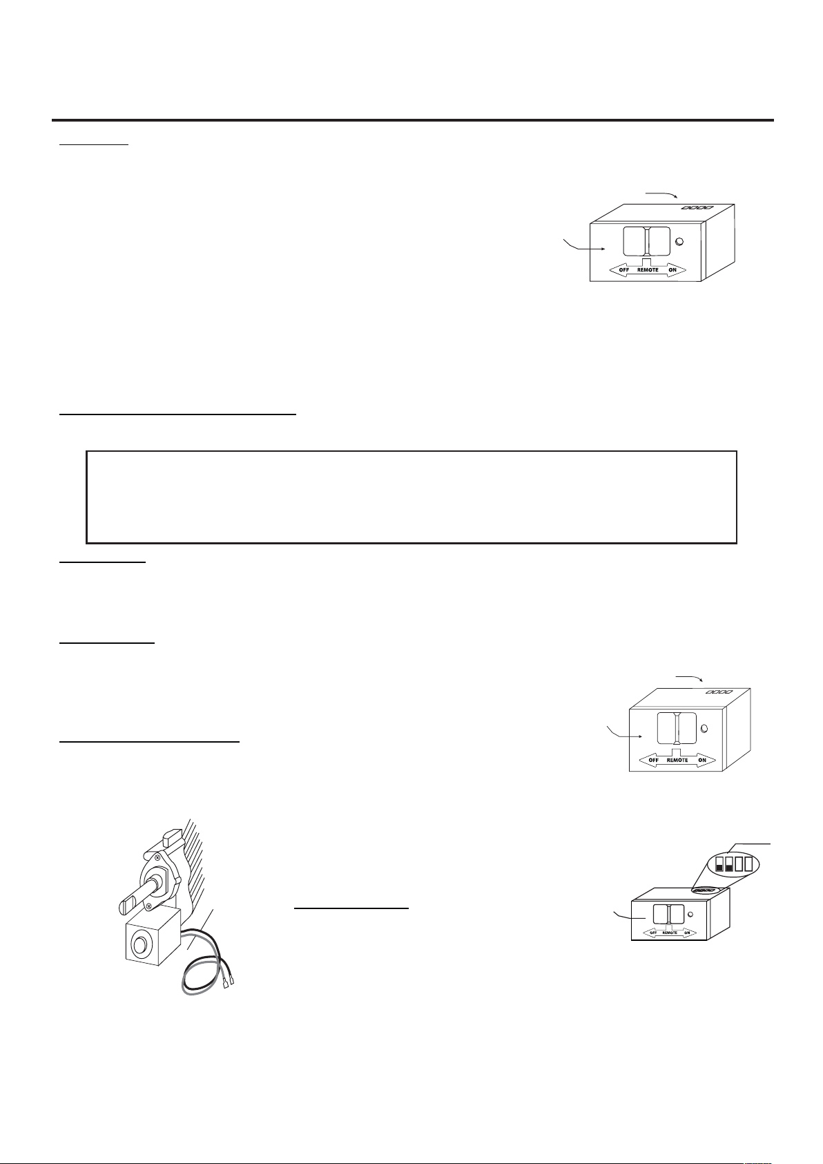
NOTE:Theremotereceiverwillonlyrespondtothetransmitterwhenthe3-position
slidebuttonontheremotereceiverisintheREMOTEposition.Theremotereceiver
houses the microprocessor that responds to commands from the transmitter to
controlsystemoperation.
ROOM
TEMP
THERMOON
ROOM
TEMP
THERMOOFF
REMOTE
ON
O
F
F
LEARN
Requires 4-AA 1.5V
alkaline batteries
Learning
button
Remote Receiver
B
a
t
t
e
ry
c
o
v
e
r
s
l
i
d
es
on
/
of
f
Slide
Switch
ON
REMOTE
OFF
THE REMOTE RECEIVER SHOULD BE POSITIONED WHERE AMBIENT
TEMPERATURES DO NOT EXCEED 130° F.
31
REMOTE CONTROL OPERATION
FUNCTIONS:
¥ WiththeslideswitchintheREMOTEposition,thesystemwillonlyoperate
iftheremotereceiverreceivescommandsfromthetransmitter.
¥ Uponinitialuseorafteranextendedperiodofnouse,theONbuttonmay
havetobepressedforuptothreesecondsbeforeactivatingservomotor.If
the system does not respond to the transmitter on initial use, see
LEARNINGTRANSMITTERTORECEIVER.
¥ With the slide switch in the ON position you can manually turn ON the
system.
¥ WiththeslideintheOFFposition,thesystemisOFF.
¥ ItissuggestedthattheslideswitchbeplacedintheOFFpositionifyouwill
beawayfromyourhomeforanextendedperiodoftime.
¥ Placing the slide switch in the OFF position also functions as a
safety"lockout"bybothturningthesystemOFFandrenderingthe
transmitterinoperative.
INSTALLATIONINSTRUCTIONS
WARNING
DO NOT CONNECT REMOTE RECEIVER DIRECTLY TO 110-120VAC POWER. THIS WILL BURN
OUT THE RECEIVER. FOLLOW INSTRUCTIONS FROM MANUFACTURER OF GAS VALVE FOR
CORRECT WIRING PROCEDURES. IMPROPER INSTALLATION OF ELECTRIC COMPONENTS
CANCAUSEDAMAGETOGASVALVEANDREMOTERECEIVER.
INSTALLATION
Theremotereceivercanbemountedonornearthefireplacehearth.PROTECTIONFROMEXTREMEHEATISVERYIMPORTANT.
Like any piece of electronic equipment, the remote receiver should be kept away from temperatures exceeding 130º F inside the
receivercase.Batterylifeisalsosignificantlyshortenedifbatteriesareexposedtohightemperatures.
HEARTHMOUNT
The remote receiver can be placed on the fireplace hearth or under the fireplace, behind the
controlaccesspanel.Positionwheretheambienttemperatureinsidethereceivercasedoesnot
exceed130ºF.NOTE:BlackButtonisusedonHearthMountApplications.
WIRINGINSTRUCTIONS
MakesuretheremotereceiverswitchisintheOFFposition.Forbestresultsitisrecommended
that18gaugestrandedwiresshouldbeusedtomakeconnectionsandnolongerthan20-feet.
ThisCON1001THremotereceiveristobeconnected
toamanualvalvewithalatchingON/OFFsolenoid.
Connecttwo18gaugestrandedorsolidwiresfromthe
remote receiver terminals to the latching solenoid.
(Seefiguretotheright)
IMPORTANT NOTE: Operation of this control is
dependentonwhichwireisattachedtowhichterminal.
Ifoperationofcontroldoesnotcorrespondtooperating
buttons on transmitter, reverse wire installation at the
receiveroratthecontrol.
Black Wire
Red Wire
Pulse Connection
Concentric Valve
Wire terminals
Remote Receiver
Receiver
Slide
Button
REMOTE
OFF
ON
LEARN
Wire terminals
Remote Receiver
Receiver
Slide
Button
REMOTE
OFF
ON
LEARN
Remote Receiver
Receiver
Slide
Button
REMOTE
OFF
PULSE MODE
Terminals
LEARN
ON
DO NOT CONNECT REMOTE RECEIVER DIRECTLY TO 110-120VAC POWER. THIS WILL BURN
OUT THE RECEIVER. FOLLOW INSTRUCTIONS FROM MANUFACTURER OF GAS VALVE FOR
CORRECT WIRING PROCEDURES. IMPROPER INSTALLATION OF ELECTRIC COMPONENTS CAN
CAUSE DAMAGE TO GAS VALVE AND REMOTE RECEIVER.

32
REMOTE CONTROL OPERATION
GENERALINFORMATION
COMMUNICATION–SAFETY–TRANSMITTER
ThisremotecontrolhasaCOMMUNICATION–SAFETYfunctionbuiltintoitssoftware.Itprovidesanextramarginofsafetywhenthe
TRANSMITTERisoutofthenormal20-footoperatingrangeofthereceiver.
TheCOMMUNICATION–SAFETYfeatureoperatesinthefollowingmanner,inallOPERATINGMODES–ON/ONTHERMO.
AtalltimesandinallOPERATINGMODES,thetransmittersendsanRFsignaleveryfifteen(15)minutes,tothereceiver,indicating
that the transmitter is within the normal operating range of 20-feet. Should the receiver NOT receive a transmitter signal every 15
minutes,theICsoftware,intheRECEIVER,willbegina2-HOUR(120-minute)countdowntimingfunction.Ifduringthis2-hourperiod,
thereceiverdoes notreceiveasignalfromthetransmitter,thereceiverwillshutdowntheappliancebeingcontrolledbythereceiver.
The RECEIVER will then emit a series of rapid “beeps” for a period of 10 seconds. Then after 10 seconds of rapid beeping, the
RECEIVER will continue to emit a single “beep” every 4 seconds until a transmitter ON or MODE Button is pressed to reset the
receiver.Theintermittent4-secondbeepingwillgoonforaslongasthereceiver’sbatterieslastwhichcouldbeinexcessofoneyear.
To “reset” the RECEIVER and operate the appliance, you must press the ON or MODE button on the transmitter. By turning the
systemtoON,theCOMMUNICATION-SAFETYoperationisoverriddenandthesystemwillreturntonormaloperationdependingon
theMODEselectedatthetransmitter.TheCOMMUNICATION–SAFETYfeaturewillreactivateshouldthetransmitterbetakenoutof
thenormaloperatingrangeorshouldthetransmitter’sbatteriesfailorberemoved.
CP(CHILDPROOF)FEATURE
ThisremotecontrolincludesaCHILDPROOF“LOCK-OUT”featurethatallowstheuserto“LOCK-OUT”operationoftheappliance,
fromtheTRANSMITTER.
SETTING“LOCK-OUT”–(CP)
¥ Toactivatethe“LOCK-OUT”feature,pressandholdtheONbuttonandtheMODEbuttonatthesametimefor5seconds.The
lettersCPwillappearintheTEMPframeontheLCDscreen.
¥ Todisengagethe“LOCK-OUT”,pressandholdtheONbuttonandtheMODEbuttonatthesametimefor5secondsandtheletters
CPwilldisappearfromtheLCDscreenandthetransmitterwillreturntoitsnormaloperatingcondition.
¥ ToverifythattransmitterisintheCPlock-outmodepressanykeyandtheLCDscreenwillshow“CP”
NOTE:IftheapplianceisalreadyoperatingintheONorTHERMOMODES,engagingthe“LOCK-OUT”willnotcanceltheoperating
MODE.Engagingthe“LOCK-OUT”preventsonlythemanualoperationoftheTRANSMITTER.Ifintheautomodes,theTHERMO
operationwillcontinuetooperatenormally.Tototally“LOCK-OUT”theoperationoftheTRANSMITTER’Soperatingsignals;the
transmitter’sMODEmustbesettoOFF.
LEARNINGTRANSMITTERTORECEIVER
Eachtransmitterusesauniquesecuritycode.ItwillbenecessarytopresstheLEARNbuttononthereceivertoacceptthetransmitter
securitycodeuponinitialuse,ifbatteriesarereplaced,orifareplacementtransmitterispurchasedfromyourdealerorthefactory.In
orderforthereceivertoacceptthetransmittersecuritycode,besuretheslidebuttononthereceiverisintheREMOTEposition;the
receiverwillnotLEARNiftheslideswitchisintheONorOFFposition.TheLEARNbuttoninlocatedonthefrontfaceofthereceiver;
insidethesmallholelabeledLEARN.UsingasmallscrewdriverorendofapaperclipgentlypressandreleasetheblackLEARNbutton
insidethehole.WhenyoureleasetheLEARNbuttonthereceiverwillemitanaudible“beep”.Afterthereceiveremitsthebeeppress
thetransmitterANYbuttonandrelease.Thereceiverwillemitseveralbeepsindicatingthatthetransmitter’scodehasbeenaccepted
intothereceiver.
Themicroprocessorthatcontrolsthe securitycodematchingprocedure iscontrolledbya timing function.Ifyouareunsuccessfulin
matchingthesecuritycodeonthefirstattempt,wait1-2minutesbeforetryingagain--thisdelayallowsthemicroprocessortoresetits
timercircuitry--andtryuptotwoorthreemoretimes.

33
REMOTE CONTROL OPERATION
BATTERYLIFE
Replaceallbatteriesregularly.Whenthetransmitternolongeroperatestheremotereceiverfromadistanceitdidpreviously(i.e.,the
transmitter'srangehasdecreased)ortheremotereceiverdoesnotfunctionatall,thebatteriesshouldbechecked.Itisimportantthat
theremotereceiverbatteriesarefullycharged,providingcombinedoutputvoltageofatleast5.5volts.Thehandheldtransmittershould
operatewithaslittleas2.5voltsbatterypower.
TROUBLESHOOTING
If you encounter problems with your fireplace system, the problem may be the fireplace itself or it could be with theremote
system.Reviewthefireplacemanufacturer'soperationmanualtomakesureallconnectionsareproperlymade.Thencheckthe
operationoftheremoteinthefollowingmanner:
¥ MakesurethebatteriesarecorrectlyinstalledintheRECEIVER.Onereversedbatterywillkeepreceiverfromoperatingproperly.
¥ CheckbatteryinTRANSMITTERtoensurecontactsaretouching(+)and(-)endsofbattery.Bendmetalcontactsinfortighterfit.
¥ BesureRECEIVERandTRANSMITTERiswithin20-feetoperatingrange.
¥ ClearCodes:Memoryinthereceivermightbefullifthelearnbuttonispressedtoomanytimes.Ifthishappensitwillnotallowany
morecodestobelearnedandnoaudiblebeepwillbeheard.Toclearmemory,placethereceiverslideswitchintotheREMOTE
position.Pressthelearnbuttonandreleaseafter10seconds.Youshouldhearthree(3)longaudiblebeepsindicatingallcodes
havecleared.Youcannow“learn”thetransmittertothereceiverasdescribedintheGeneralInformationSection.
¥ KeepRECEIVERfromtemperaturesexceeding130°F.Batterylifeshortenedwhenambienttemperaturesareabove115°F.
¥ IfRECEIVERisinstalledintightlyenclosedmetalsurround,theoperatingdistancewillbeshortened.
¥ Rechargeablebatteriesshouldnotbeused.Theydonotsupplysufficientpowertooperatetheremotesystem.
SPECIFICATIONS
BATTERIES: Transmitter(2)1.5voltAAAbatteries
RemoteReceiver6V-4ea.AA1.5Alkaline
FCCIDNo.'s:transmitter-2ARLSGH03-C
FCC REQUIREMENTS
NOTE: THE MANUFACTURER IS NOT RESPONSIBLE FOR ANY RADIO OR TV INTERFERENCE CAUSED BY
UNAUTHORIZED MODIFICATIONS TO THIS EQUIPMENT. SUCH MODIFICATIONS COULD VOID THE USER’S
AUTHORITY TO OPERATE THE EQUIPMENT.
34
OPERATION
INSPECTING BURNERS
Checkpilotamepatternandburneramepatternsoften.
PILOT FLAME PATTERN
Figure20showsacorrectpilotamepattern.Figure21showsanincorrectpilotamepattern.The
incorrectpilotameisnottouchingthethermocouple.Thiswillcausethethermocoupletocool.When
thethermocouplecools,the�replacewillshutdown.
Ifpilotamepatternisincorrect,asshowninFigure21.
•Turn�replaceoff(seeToTurnOffGastoAppliance,page27.
• See Troubleshooting, page 37.
Note:Thepilotameonnaturalgasunitswillhaveaslightcurve,butameshouldbeblueandhave
no yellow or orange color.
WARNING: If yellow tipping occurs, your heater could produce increased levels of carbon
monoxide.Ifburneramepatternshowsyellowtipping,followinstructionsatbottomofthis
page.
WARNING:Donotallowfanstoblowdirectlyintothe�replace.Avoidanydraftsthatalterburner
amepatterns.
WARNING: Do not use a blower insert, heat exchanger insert or other accessory not approved for
use with this heater.
Notice:Donotmistakeorangeameswithyellowtipping.Dirtorother�neparticlesentertheheater
andburncausingbriefpatchesoforangeame.
Fig. 20 - Correct Pilot Flame Pattern Fig. 21 - Incorrect Pilot Flame Pattern
LP PILOT
NG PILOT
LP PILOT
NG PILOT
35
CARE AND MAINTENANCE
WARNING: Turn off heater and let cool before servicing.
CAUTION: You must keep control areas, burner, and circulating air passageways of heater
clean. Inspect these areas of heater before each use. Have heater inspected yearly by a
quali�edserviceperson.Heatermayneedmorefrequentcleaningduetoexcessivelint
from carpeting, bedding material, pet hair, etc.
WARNING: Failure to keep the primary air opening(s) of the burner(s) clean may result in sooting
and property damage.
BURNER ORIFICE HOLDER AND PILOT AIR INLET HOLE
The primary air inlet holes allow the proper amount of air to mix with the gas. This provides a clean
burningame.Keeptheseholesclearofdust,dirt,lintandpethair.Cleantheseairinletholespriorto
each heating season. Blocked air holes will create soot. We recommend that you clean the unit every
threemonthsduringoperationandhave�replaceinspectedyearlybyaquali�edserviceperson.
We also recommend that you keep the burner tube and pilot assembly clean and free of dust and dirt.
To clean these parts we recommend using compressed air no greater than 30 PSI. Your local
computer store, hardware store or home center may carry compressed air in a can. If using
compressed air in a can, please follow the directions on the can. If you don’t follow directions on the
can, you could damage the pilot assembly.
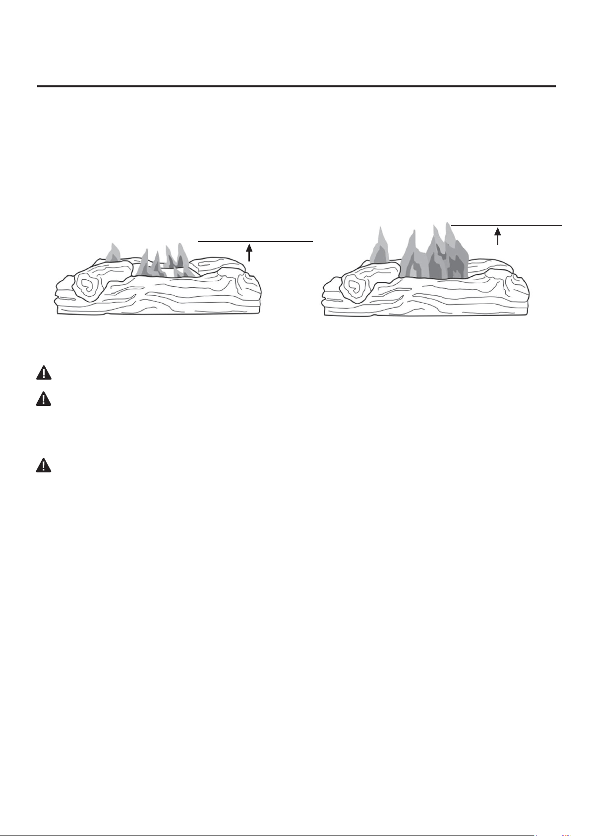
BURNER FLAME PATTERN
Figure22showsacorrectburneramepattern.Figure23showsanincorrectburneramepattern.
Theincorrectburneramepatternshowssporadic,irregularametipping.Theameshouldnotbe
dark or have an orange/reddish tinge.
Note:Whenusingthe�replacethe�rsttime,theamewillbeorangeforapproximatelyonehouruntil
the log cures.
Ifburneramepatternisincorrect,asshowninFigure23
•turn�replaceoff(seeToTurnOffGastoAppliance,page27).
• see Troubleshooting, page 37.
2-3 inches
above logs
6-12 inches
above logs
Fig. 22 - Correct Burner Flame Pattern Fig. 23 - Incorrect Burner Flame
Pattern
36
CARE AND MAINTENANCE
LOG SET
• If you remove the log set for cleaning, refer to pages 23 & 24, for placement instructions.
• Replace log set if broken or chipped (dime sized or larger).
CABINET
Air Passageways
Use a vacuum cleaner or pressurized air to clean.
Exterior
Use a soft cloth dampened with a mild soap and water mixture. Wipe the cabinet to remove dust.
Fig. 24 - Primary Air Inlet
Slot on Burner Tube
1. Shut off unit including pilot. Allow unit to cool for at least 30 minutes.
2. Inspectburner,pilotandprimaryairinletholesonori�ceholderfordustanddirt(SeeFig.24).
3. Blow air through the ports/slots and holes in the burner.
4. Checktheori�ceholderlocatedattheendoftheburnertubeagain.Removeanylargeparticles
of dust, dirt, lint or pet hair with a soft cloth or vacuum cleaner nozzle.
5. Blowairintotheprimaryairholesontheori�ceholder.
6. In case any large clumps of dust have now been pushed into the burner repeat steps 3 and 4.
Cleanthepilotassemblyalso.Ayellowtiponthepilotameindicatesdustanddirtinthepilot
assembly.Thereisasmallpilotairinletholeabout2"fromwherethepilotamecomesoutof
the pilot assembly (see Figure 25 depending on model). With the unit off, lightly blow air through
the air inlet hole. You may blow through a drinking straw if compressed air is not available.
Fig. 25 - Pilot Inlet Air Hole
LP Pilot Air
Inlet Hole
NG Pilot Air
Inlet Hole
Primary Air
Inlet Hole
Burne
r
Shutter
Burner
Tube
Primary Air
Inlet Slot
Shutter
LP PILOT
NG PILOT
*Werecommendthatyoucleantheuniteverythreemonthsduringoperationandhave�replaceinspected
yearlybyaquali�edserviceperson.Failuretokeeptheprimaryairopening(s)oftheburner(s)cleanmay
resultinsootingandpropertydamage.
37
TROUBLESHOOTING
WARNING: If you smell gas:
• Shut off gas supply.
• Do not try to light any appliance.
• Do not touch any electrical switch; do not use any phone in your building.
• Immediately call your gas supplier from a neighbor’s phone. Follow the gas supplier’s instructions.
•Ifyoucannotreachyourgassupplier,callthe�redepartment.
IMPORTANT: Operating heater where impurities in air exist may create odors. Cleaning supplies, paint, paint
remover, cigarette smoke, cements and glues, new carpet or textiles, etc., create fumes. These fumes may mix
with combustion air and create odors.
WARNING: Make sure that power is turned off before proceeding.
WARNING:Turnoffandletcoolbeforeservicing.Onlyaquali�edservicepersonshouldservice
and repair heater.
CAUTION: Never use a wire, needle, or similar object to clean ODS/pilot. This can damage ODS/ pilot unit.
PROBLEM POSSIBLE CAUSE CORRECTIVE ACTION
When ignitor button
is pressed in, there
is no spark at ODS/
pilot.
1. Ignitor electrode is
positioned wrong.
2. Ignitor electrode is broken.
3. Ignitor electrode is not
connected to ignitor cable.
4. Ignitor cable is pinched or
wet.
5. Damaged ignitor cable.
6. Bad push button ignitor.
1. Replace electrode.
2. Replace electrode.
3. Replace ignitor cable.
4. Free ignitor cable if pinched by any
metal or tubing. Keep ignitor cable dry.
5. Replace ignitor cable.
6. Replace push button ignitor.
When ignitor button
is pressed in, there
is a spark at ODS/
pilot but no ignition.
1. Gas supply is turned off or
equipment shutoff valve is
closed.
2. Control knob not fully
pressed in while pressing
ignitor button.
3. Air in gas lines when
installed.
4. ODS / pilot is clogged.
5. Gas regulator setting is not
correct.
6. Control knob not in PILOT
position.
7. Depleted gas supply (propane).
1. Turn on gas supply or open equipment
shutoff valve.
2. Fully press in control knob while
pressing ignitor button.
3. Continue holding down control knob.
Repeat igniting operation until air is
removed.
4. Clean ODS/pilot (see Care and
Maintenance, page 35) or replace
ODS/pilot assembly.
5. Replace gas regulator.
6. Turn control knob to PILOT position.
7. Contact local propane/LP gas company.
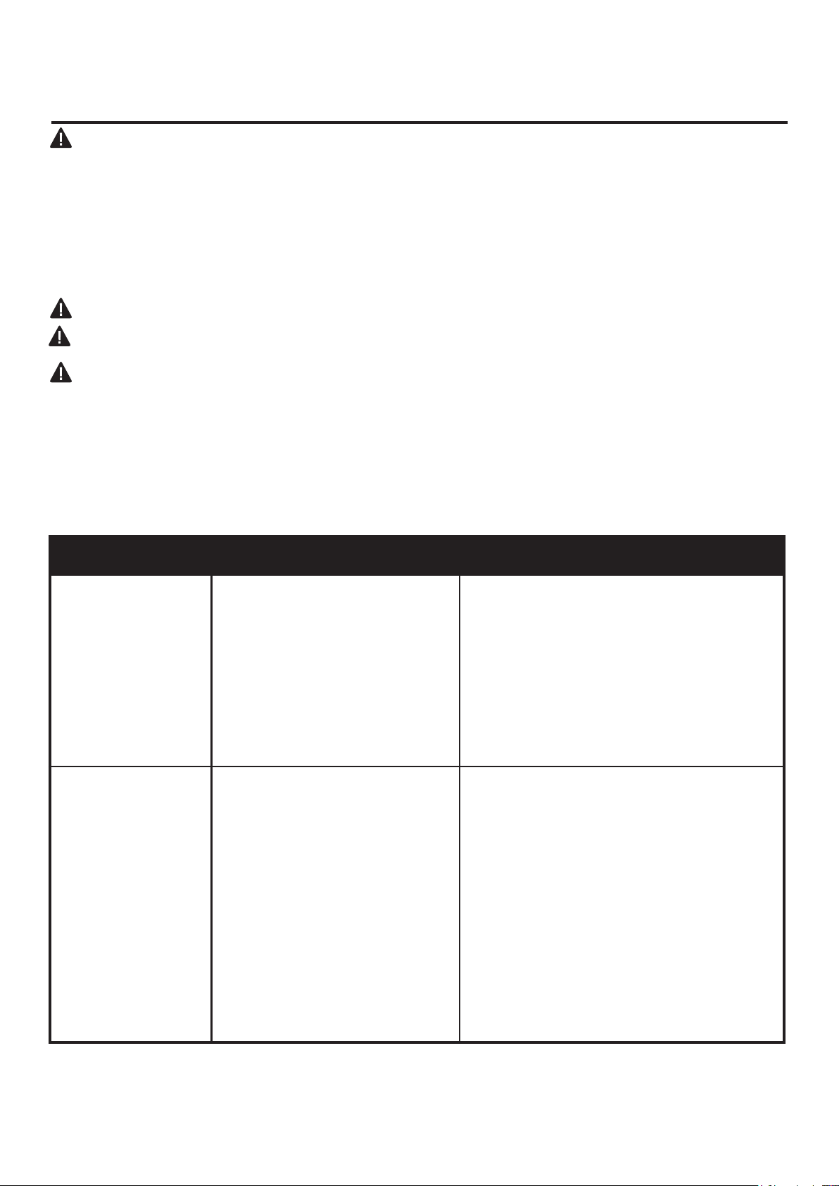
SERVICE HINTS
When Gas Pressure Is Too Low
• Pilot will not stay lit.
• Burners will have delayed ignition.
•Fireplacewillnotproducespeci�edheat.
• For propane/LP units, propane/LP gas supply may be low.
You may feel your gas pressure is too low. If so, contact your local natural or propane/LP gas supplier.

38
TROUBLESHOOTING
PROBLEM POSSIBLE CAUSE CORRECTIVE ACTION
ODS/pilot lights
butamegoesout
when control knob is
released.
1. Control knob is not fully
pressed in.
2. Control knob is not pressed
in long enough.
3. Equipment shutoff valve is
not fully open.
4. Thermocouple connection is
loose.
5. Thermocouple damaged.
6. Control valve damaged.
1. Press in control knob fully.
2. After ODS/pilot lights, keep control
knob pressed in 30 seconds.
3. Fully open equipment shutoff valve.
4. Hand tighten until snug, and then
tighten ¼ turn more.
5. Replace thermocouple.
6. Contact customer service.
Burner(s) does not
light after ODS/pilot
is lit.
1.Burnerori�ceisclogged.
2.Burnerori�cediameteris
too small.
3. Inlet gas pressure is too low.
1.Cleanburnerori�ce(seeCareand
Maintenance, page 35) or contact
customer service.
2. Contact customer service.
3. Contact your gas supplier.
Delayed ignition of
burner(s).
1. Manifold pressure is too low.
2.Burnerori�ceisclogged.
1. Contact your gas supplier.
2. Clean burner (see Care and
Maintenance, page 35) or contact
customer service.
Burnerback�ring
during combustion.
1.Burnerori�ceiscloggedor
damaged.
2. Burner is damaged.
3. Gas regulator is damaged.
1.Cleanburnerori�ce(seeCareand
Maintenance, page 35 or contact
customer service.
2. Contact dealer or customer service.
3. Replace gas regulator.
Highyellowame
during burner
combustion.
1. Not enough air.
2. Gas regulator is defective.
3. Inlet gas pressure is too low.
1. Check burner for dirt and debris. If found, clean
burner (see Care and Maintenance, page 35).
2. Replace gas regulator.
3. Contact your gas supplier.
Gas odor during
combustion.
1. Foreign matter between
control valve and burner.
2. Gas leak. (See Warning
Statement at top of page 26).
1. Take apart gas tubing and remove
foreign matter.
2. Locate and correct all leaks (see
“Checking Gas Connections,” page 25).
Heater produces a
clicking/ticking noise
just after burner is lit
or shut off.
1. Metal is expanding while
heating or contracting
while cooling.
1. This is common with most heaters. If
noiseisexcessive,contactquali�ed
service technician.

39
TROUBLESHOOTING
PROBLEM POSSIBLE CAUSE CORRECTIVE ACTION
White powder
residue forming
within burner box or
on adjacent walls or
furniture.
1. When heated, the vapors
from furniture polish, wax,
carpet cleaners, etc., turn
into white powder residue.
1. Turn heater off when using furniture
polish, wax, carpet cleaner or similar
products.
Heater produces
unwanted odors.
1. Heater is burning vapors
from paint, hair spray, glues,
etc. See IMPORTANT
statement, page 26.
2. Gas leak. See Warning
Statement, page 26.
3. Low fuel supply.
1. Ventilate room. Stop using odor
causing products while heater is
running.
2. Locate and correct all leaks (see
“Checking Gas Connections,” page 25).
3.Re�llsupplytank(Propane/LPmodels).
Heater shuts off
in use (ODS
operates).
1. Not enough fresh air is
available.
2. Low line pressure.
3. ODS/pilot is partially
clogged.
1. Open window and/or door for
ventilation.
2. Contact local gas supplier.
3. Clean ODS/pilot (see Care and
Maintenance, page 35).
Gas odor exists
even when control
knob is in OFF
position.
1. Gas leak. See Warning
Statement at top of page 26.
2. Control valve is defective.
1. Locate and correct all leaks (see
“Checking Gas Connections”, page 25).
2. Contact customer service.
Moisture/
condensation
noticed on windows.
1. Not enough combustion/
ventilation air.
1. Refer to “Air for Combustion and
Ventilation” requirements, page 10-12.
Slight smoke or
odor during initial
operation.
Heater produces
a whistling noise
when burner is lit.
1. Residues from
manufacturing process.
1. Problem will stop after a few hours of
operation.
1. Turning control knob to high (5)
position when burner is cold.
2. Air in gas line.
3. Air passageways on
heater are blocked.
4. Dirty or partially clogged
burnerori�ce.
1. Turn control knob to low (1) position and
let warm up for a minute.
2. Operate burner until air is removed from
line. Have gas line checked by local
propane/LP gas company.
3. Observe minimum installation
clearances (Fig. 6, page 14).
4. Clean burner (see Care and Maintenance,
page 35) or contact customer service.
40
REPLACEMENT PARTS
For replacement parts, call our customer service department at 1-877-447-4768, 8:30 a.m. –4:30 p.m.,
CST, Monday – Friday or email us at [email protected].
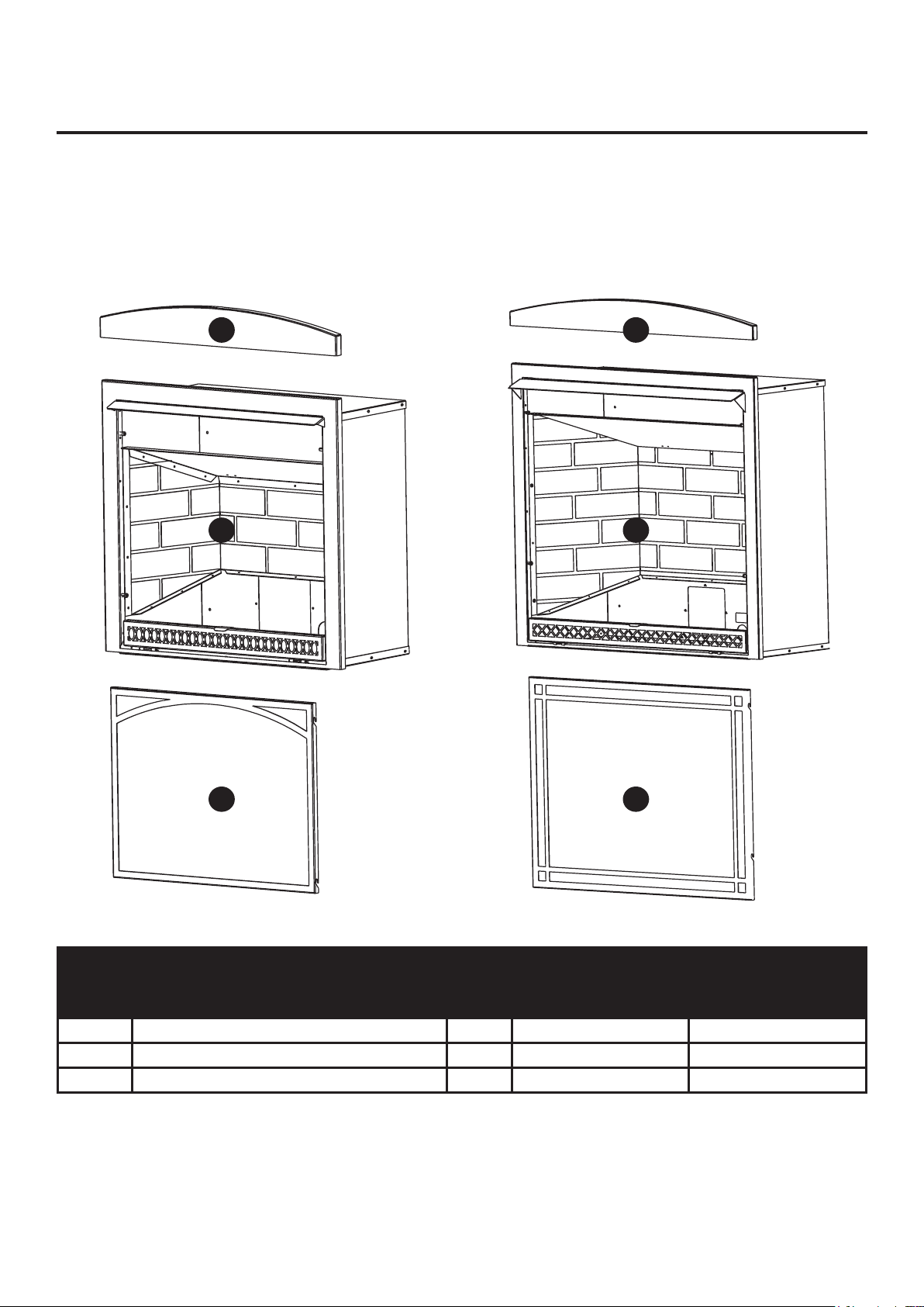
VFF-L25D VFF-L32D
ITEM
No.
DESCRIPTION QTY
PART NUMBER
VFF-L25D VFF-L32D
A Arch panel 1 80-06-448 80-06-450
B Firebox 1 80-06-449 80-06-451
C Screen 1 700-AS1015 700-AM1015
A A
B B
C C
41
For replacement parts, call our customer service department at 1-877-447-4768, 8:30 a.m. –4:30 p.m.,
CST, Monday – Friday or email us at [email protected].
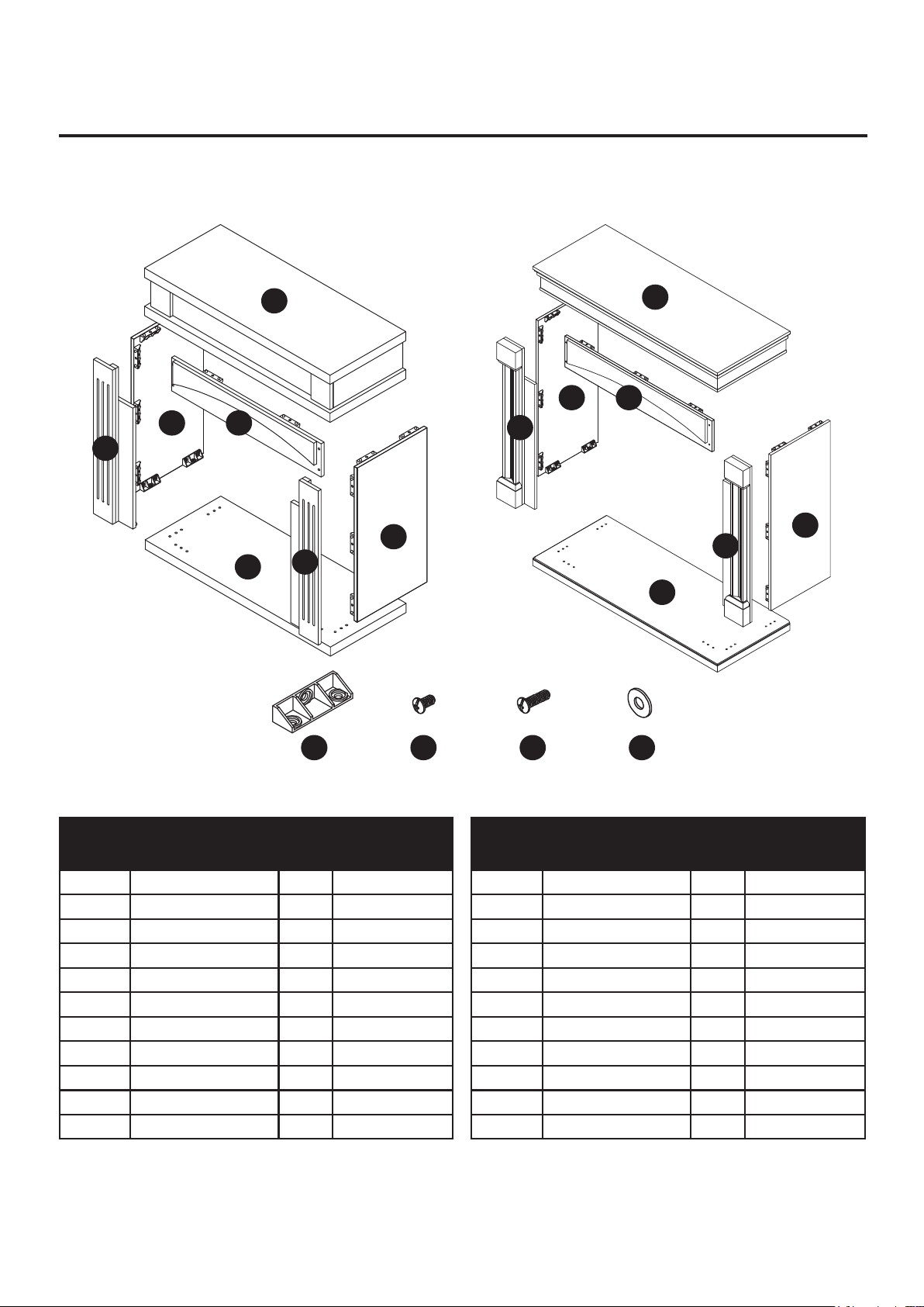
PRODUCT IDENTIFICATION
VFF-L25D
VFF-L25D
VFF-L32D
VFF-L32D
A
A
G
G
D
D
B
B
F
F
E
E
C
C
AA BB
CC DD
PART DESCRIPTION QTY Part #
A Top Panel 1 80-06-429
B Base 1 80-06-430
C Left Side Panel 1 80-06-431
D Right Side Panel 1 80-06-432
E Left Front Panel 1 80-06-433
F Right Front Panel 1 80-06-434
G Upper Front Panel 1 80-06-435
AA Connector 18 80-06-443
BB Short Bolt 54 80-06-444
CC Long Bolt 4 80-06-445
DD Washer 4 80-06-446
PART DESCRIPTION QTY Part #
A Top Panel 1 80-06-436
B Base 1 80-06-437
C Left Side Panel 1 80-06-438
D Right Side Panel 1 80-06-439
E Left Front Panel 1 80-06-440
F Right Front Panel 1 80-06-441
G Upper Front Panel 1 80-06-442
AA Connector 19 80-06-443
BB Short Bolt 57 80-06-444
CC Long Bolt 4 80-06-445
DD Washer 4 80-06-446
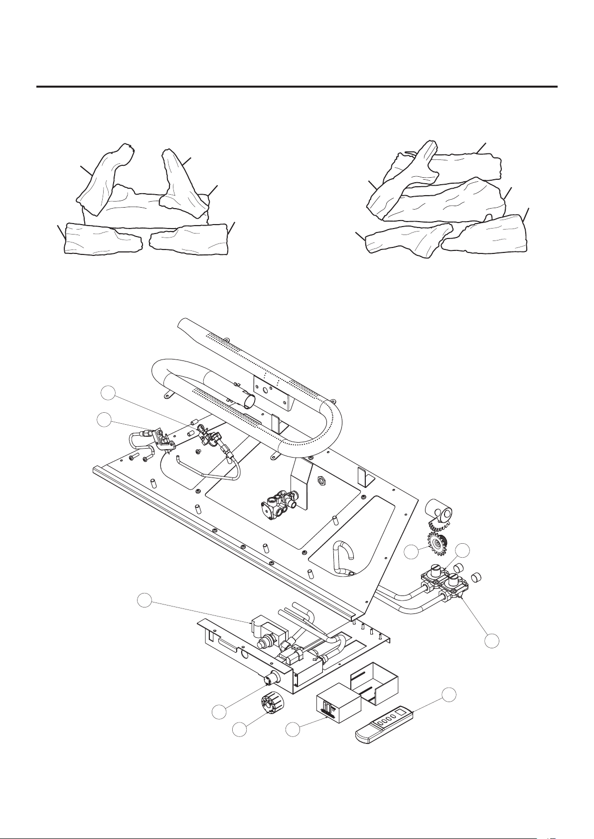
42
REPLACEMENT PARTS LIST
For replacement parts, call our customer service department at 1-877-447-4768, 8:30 a.m. –4:30 p.m.,
CST, Monday – Friday or email us at [email protected].
VFF2-PH(20D)(20DB)(20D-C)(CPD-2T)
VFF2-PH(26D)(26DB)(26D-T)(IMD-2H)
VFF2-PH(32DR)(32DRB)(32DR-H)(FSDR-2C)
1-1
1-2
1-3
1-5
1-4
1-1
1-2
1-3
1-5
1-4
2-3
2-4
4
3
2-8
2-6
2-1
2-2
2-7
2-5
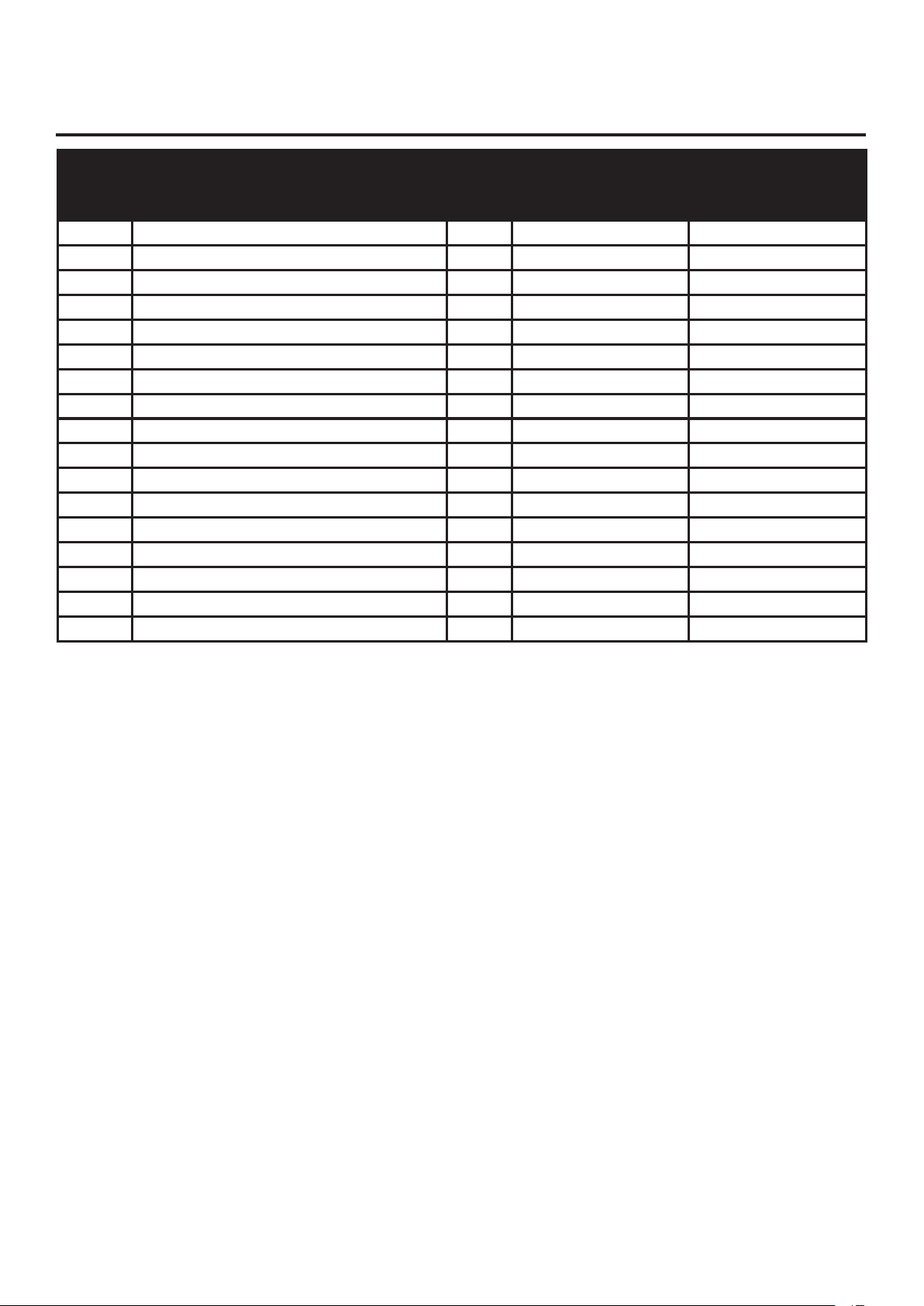
43
ITEM
No.
DESCRIPTION QTY
PART NUMBER
VFF-L25D VFF-L32D
1 Log Set (Complete) 1 700-S1018 700-L1018
1-1 Log 1 1 700-S1018-01 700-L1018-01
1-2 Log 2 1 700-S1018-02 700-M1018-02
1-3 Log 3 1 700-S1018-03 700-M1018-03
1-4 Log 4 1 700-S1018-04 700-M1018-04
1-5 Log 5 1 700-S1018-05 700-M1018-05
2 Burner Assembly (Complete) 1 700-S2000 700-L2000
2-1 ODS Pilot - NG 1 GZ20-30B GZ20-30B
2-2 ODS Pilot - LP 1 GZ20-29B GZ20-29B
2-3 Selector Knob 1 GZ20-17 GZ20-17
2-4 Regulator, (NG) Natural Gas 5" W.C. 1 GR-130B2-GHP GR-130B8-GHP
2-5 Regulator, (LP) Liquid Propane 10" W.C. 1 GR-130A2-GHP GR-130A8-GHP
2-6 Ignitor Module 1 GZ20-32a GZ20-32a
3 Remote Receiver 1 N/A 80-05-102
4 Thermostat Remote 1 N/A 80-05-101
2-7 Control Valve, EUROSIT 360 1 0630560 N/A
2-8 Control Valve 1 N/A AF-1110
REPLACEMENT PARTS LIST

44
WARRANTY
LIMITED WARRANTY
This limited warranty is extended to the original retail purchaser of this heater and warrants against any defect
in materials and workmanship for a period of two (2) years from the date of retail sale. GHP Group, Inc., at it's
option, will either provide replacement parts or replace or repair the unit, when properly returned to the retailer
where purchased or one of our service centers as directed by GHP Group, Inc., within two (2) years of retail
purchase. (Shipping costs, labor costs, etc. are the responsibility of the purchaser.
DUTIES OF THE OWNER
This heating appliance must be operated in accordance with the written instructions furnished
with this heater. This warranty shall not excuse the owner from properly maintaining this heater in accordance
with the written instructions furnished with this heater. A bill of sale, cancelled check or payment record must
be kept to verify purchase date and establish warranty period. Original carton should be kept in case of
warranty return of unit.
WHAT IS NOT COVERED
1. Damage resulting from use of improper fuel.
2. Damage caused by misuse or use contrary to the owners manual and safety guidelines.
3. Damage caused by a lack of normal maintenance.
4. Use of non-standard parts or accessories.
5. Damage caused in transit. Freight charges on warranty parts or heaters to and from the factory
shall be the responsibility of the owner.
This warranty does not imply or assume any responsibility for consequential damages that may result from the
use, misuse, or the lack of routine maintenance of this heating appliance. A cleaning fee and the cost of parts
may be charged for appliance failures resulting from lack of maintenance. This warranty does not cover claims
which do not involve defective workmanship or materials. FAILURE TO PERFORM GENERAL
MAINTENANCE (INCLUDING CLEANING) WILL VOID THIS WARRANTY.
THIS LIMITED WARRANTY IS GIVEN TO THE PURCHASER IN LIEU OF ALL OTHER WARRANTIES,
EXPRESSED OR IMPLIED , INCLUDING BUT NOT LIMITED TO THE WARRANTIES OF
MERCHANTABILITY OF FITNESS FOR A PARTICULAR PURPOSE. THE REMEDY PROVIDED IN THIS
WARRANTY IS EXCLUSIVE AND IS GRANTED IN LIEU OF ALL OTHER REMEDIES. IN NO EVENT WILL
GHP GROUP, INC. BE LIABLE FOR INCIDENTAL OR CONSEQUENTIAL DAMAGES
Some states do not allow limitations on how long an implied warranty lasts, so the above limitations may not
apply to you. Some states do not allow the exclusion or limitation of incidental or consequential damages so
the above limitation or exclusion may not apply to you.
Printed in China