Loading ...
Loading ...
Loading ...
2
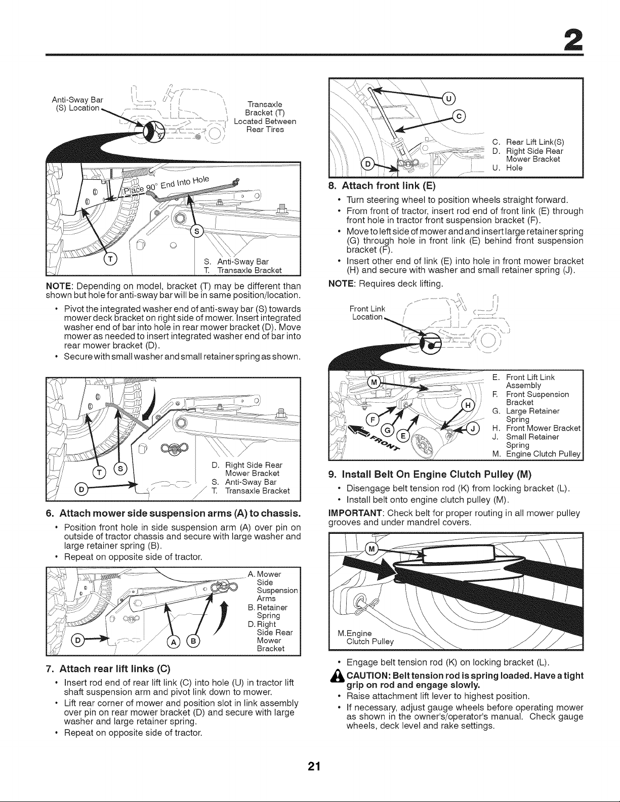
Anti-Sway Bar
(S) Location
7 Transaxle
'_ Bracket (T)
................;. ...................Located Between
Rear Tires
©
S. Anti-Sway Bar
T. Transaxle Bracket
NOTE: Depending on model, bracket (T) may be different than
shown but hole for anti-sway bar will be in same position/location.
• Pivot the integrated washer end of anti-sway bar (S) towards
mower deck bracket on right side of mower. Insert integrated
washer end of bar into hole in rear mower bracket (D). Move
mower as needed to insert integrated washer end of bar into
rear mower bracket (D).
• Secure with small washer and small retainer spring as shown.
D. Right Side Rear
Mower Bracket
S. Anti-Sway Bar
J T. Transaxle Bracket
J
6. Attach mower side suspension arms (A) to chassis.
• Position front hole in side suspension arm (A) over pin on
outside of tractor chassis and secure with large washer and
large retainer spring (B).
• Repeat on opposite side of tractor.
A. Mower
Side
Suspension
Arms
Spring
Side Rear
Mower
Bracket
7. Attach rear lift links (C)
• insert rod end of rear lift link (C) into hole (U) in tractor lift
shaft suspension arm and pivot link down to mower.
• Lift rear corner of mower and position slot in link assembly
over pin on rear mower bracket (D) and secure with large
washer and large retainer spring.
• Repeat on opposite side of tractor.
C. Rear Lift Link(S)
D. Right Side Rear
Mower Bracket
U. Hole
8. Attach front link (E)
• Turn steering wheel to position wheels straight forward.
• From front of tractor, insert rod end of front link (E) through
front hole in tractor front suspension bracket (F).
• Move to left side of mower and and insert large retainer spring
(G) through hole in front link (E) behind front suspension
bracket (F).
• Insert other end of link (E) into hole in front mower bracket
(H) and secure with washer and small retainer spring (J).
NOTE: Requires deck lifting.
/' )
Front Link / ;;::::::
Location_ ,_.........i / ................................,,
E. Front Lift Link
Assembly
R Front Suspension
Bracket
G. Large Retainer
Spring
H. Front Mower Bracket
J. Small Retainer
Spring
M. Engine Clutch Pulley
9. Install Belt On Engine Clutch Pulley (M)
• Disengage belt tension rod (K) from locking bracket (L).
• install belt onto engine clutch pulley (M).
IMPORTANT: Check belt for proper routing in all mower pulley
grooves and under mandrel covers.
M.Engine
Clutch Pulley
• Engage belt tension rod (K) on locking bracket (L).
d_lb CAUTION: Belt tension rod is loaded, Havespring
a
tight
grip on rod and engage slowly.
• Raise attachment lift lever to highest position.
• If necessary, adjust gauge wheels before operating mower
as shown in the owner's/operator's manual. Check gauge
wheels, deck level and rake settings.
21
Loading ...
Loading ...
Loading ...