Loading ...
Loading ...
Loading ...
BR N
QP3 SERIES
LAMP SOCKET
BRACKET
LIGHT
PANEL SCREWS
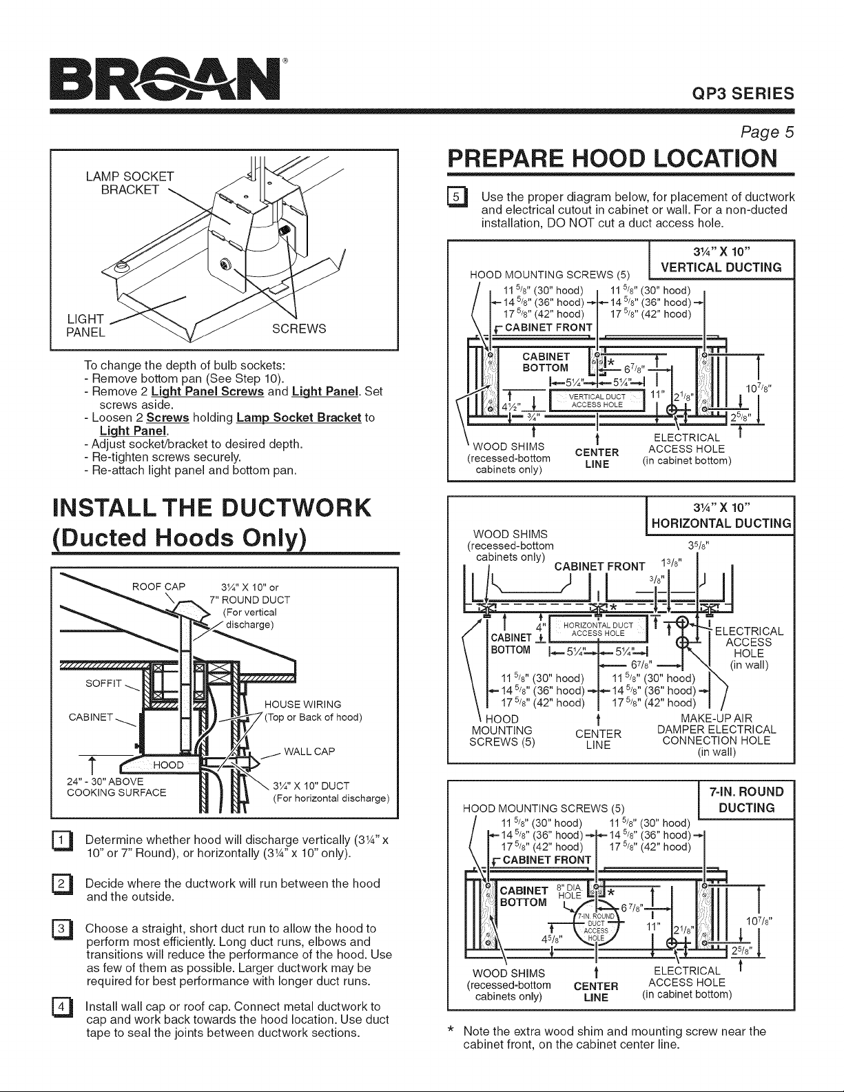
To change the depth of bulb sockets:
- Remove bottom pan (See Step 10).
- Remove 2 L_ght Panel Screws and _ Panel. Set
screws aside.
- Loosen 2 Screws holding Lamp Socket Bracket to
Panel.
- Adjust socket/bracket to desired depth.
- Re-tighten screws securely.
- Re-attach light panel and bottom pan.
Page 5
PREPARE HOOD LOCATION
El Use the for of ductwork
diagram
below,
placementproper
and electrical cutout in cabinet or wall. For a non-ducted
installation, DO NOT cut a duct access hole.
i 31A'' X 10"
HOOD MOUNTING SCREWS (5) VERTICAL DUCTING
hood) I 115/8"(30"hood)
(36" hood) _ 14 5/8" (36" hood) --,
(42" hood)/ 175/8"(42" hood)
.a , i |
il II illI 107,8,
_'_ ,:;J f j J VERTiCALDUCT J 11" j21/8"Ji.)|l J I I
( ACCESS HOLE =
\I 14½" {, [ ACCESSHOU J I _ m " I
\ I -_. m ¾ .... _-- _=_ _ 25/8" _,
\ t t ELECTRICAL I'
-- WOOD SHIMS CENTER ACCESS HOLE
(recessed-bottom LINE (in cabinet bottom)
cabinets only)
INSTALL THE DUCTWORK
(Ducted Hoods Only)
ROOF CAP
3¼" X 10" or
7" ROUND DUCT
(For vertical
SOFFIT
HOUSE WIRING
) or Back of hood)
WALL CAP
t HOOD
24"- 30"ABOVE 3¼"X 10" DUCT
COOKING SURFACE
(For horizontal discharge)
53
El
El
Determine whether hood will discharge vertically (3W' x
10" or 7" Round), or horizontally (3W' x 10" only).
Decide where the ductwork will run between the hood
and the outside.
Choose a straight, short duct run to allow the hood to
perform most efficiently. Long duct runs, elbows and
transitions will reduce the performance of the hood. Use
as few of them as possible. Larger ductwork may be
required for best performance with longer duct runs.
[_ Install wall roof Connect metal ductwork to
cap
or
cap.
cap and work back towards the hood location. Use duct
tape to seal the joints between ductwork sections.
3Y4" X 10"
HORIZONTAL DUCTING
WOOD SHIMS
(recessed-bottom 35/8"
cabinets only)
i CABINET FRONT 13/8" i
CABINET _ I ACCESS HOLE | I 1 . I ELF--_._|r_I',._/-',L
_z__ , _ _ '- ACCESS
BOTTOM I HOLE
67/8,, ..=._ X,_. (in wall)
5/ 5/
11 8" (30" hood) I 11_8" (30" hood) I_,
_ 14 5/8'' (36" hood)-_*= 14 5/8'' (36" hood) =_
5/ 5/
17 8"(42" hood) I 17 8" (42" hood) I /
HOOD _ MAKE-UP AIR
MOUNTING CENTER DAMPER ELECTRICAL
SCREWS (5) LINE CONNECTION HOLE
(in wall)
HOOD MOUNTING SCREWS (5)
115/8"(30"hood) 115/8"(30"hood)
(36"hood)
(42"hood)
7-IN. ROUNDDUCTING
107/8"
WOOD SHIMS _' ELECTRICAL
(recessed-bottom CENTER ACCESS HOLE
cabinets only) LINE (in cabinet bottom)
* Note the extra wood shim and mounting screw near the
cabinet front, on the cabinet center line.
Loading ...
Loading ...
Loading ...