ELITE INTERACTIVE SERIES
EXERCISE BIKE
SF-B220045
USER MANUAL
IMPORTANT! Please retain owner’s manual for maintenance and adjustment instructions. Your
satisfaction is very important to us, PLEASE DO NOT RETURN UNTIL YOU HAVE CONTACTED
US: [email protected] or 1-877-90SUNNY (877-907-8669).

1
IMPORTANT SAFETY INFORMATION
We thank you for choosing our product. To ensure your safety and health, please use this
equipment correctly. It is important to read this entire manual before assembling and using the
equipment. Safe and effective use can only be achieved if the equipment is assembled, maintained,
and used properly. It is your responsibility to ensure that all users of the equipment are informed of
all warnings and precautions.
1. Before starting any exercise program, you should consult your physician to determine if you
have any medical or physical conditions that could put your health and safety at risk or prevent
you from using the equipment properly. Your physician’s advice is essential if you are taking
medication that affects your heart rate, blood pressure, or cholesterol level.
2. Be aware of your body’s signals. Incorrect or excessive exercise can damage your health. Stop
exercising if you experience any of the following symptoms: pain, tightness in your chest,
irregular heartbeat, shortness of breath, lightheadedness, dizziness, or feelings of nausea. If
you do experience any of these conditions, you should consult your physician before continuing
with your exercise program.
3. Keep children and pets away from the equipment. The equipment is designed for adult use only.
4. Use the equipment on a solid, flat level surface with a protective cover for your floor or carpet.
To ensure safety, the equipment should have at least 2 feet (60 CM) of free space all around it.
5. Ensure that all nuts and bolts are securely tightened before using the equipment. The safety of
the equipment can only be maintained if it is regularly examined for damage and/or wear and
tear.
6. Always use the equipment as indicated. If you find any defective components while assembling
or checking the equipment, or if you hear any unusual noises coming from the equipment during
exercise, discontinue use of the equipment immediately and do not use until the problem has
been rectified.
7. Wear suitable clothing while using the equipment. Avoid wearing loose clothing that may
become entangled in the equipment.
8. Do not place fingers or objects into the moving parts of the equipment.
9. The maximum weight capacity of this unit is 275 pounds (125 KG).
10. The equipment is not suitable for therapeutic use.
11. To avoid bodily injury and/or damage to the product or property, proper lifting and moving are
required.
12. Your product is intended for use in cool, dry conditions. You should avoid storage in extreme
cold, hot, or damp areas as this may lead to corrosion and other related problems.
13. This equipment is designed for indoor and home use only; it is not intended for commercial use.
2
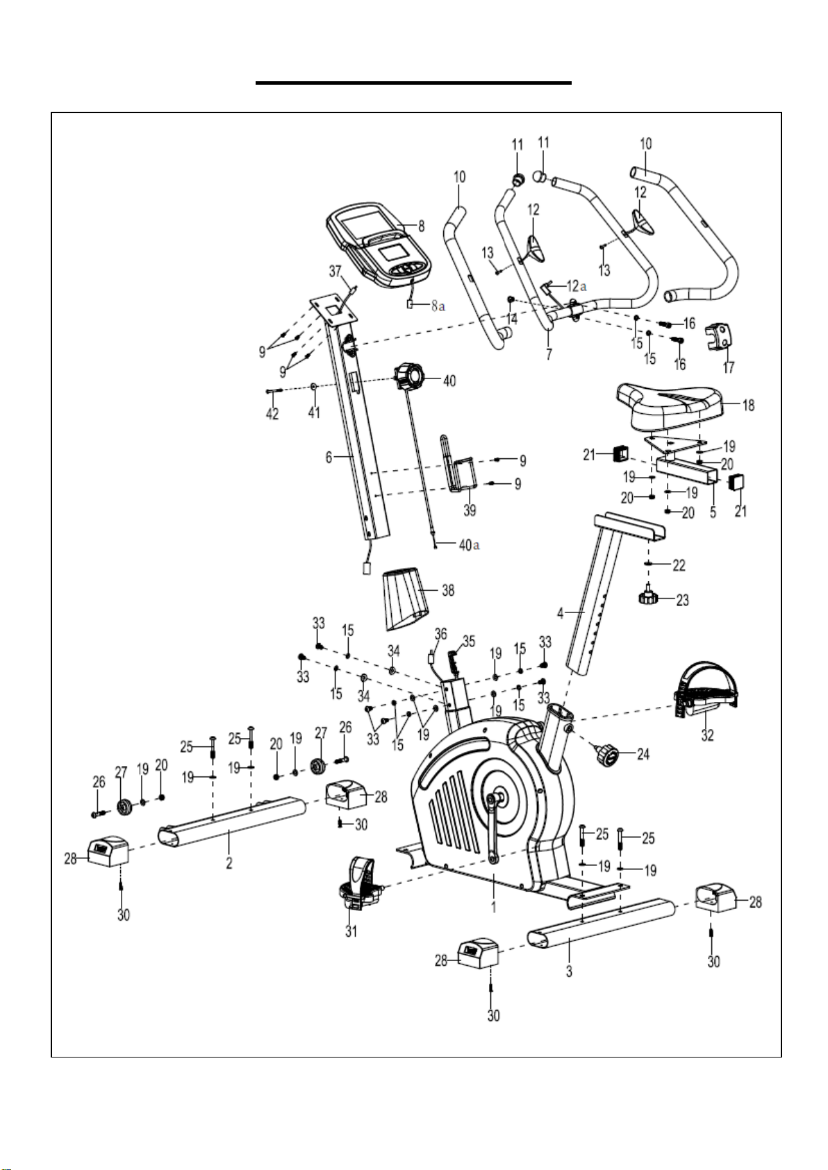
EXPLODED DIAGRAM 1
3
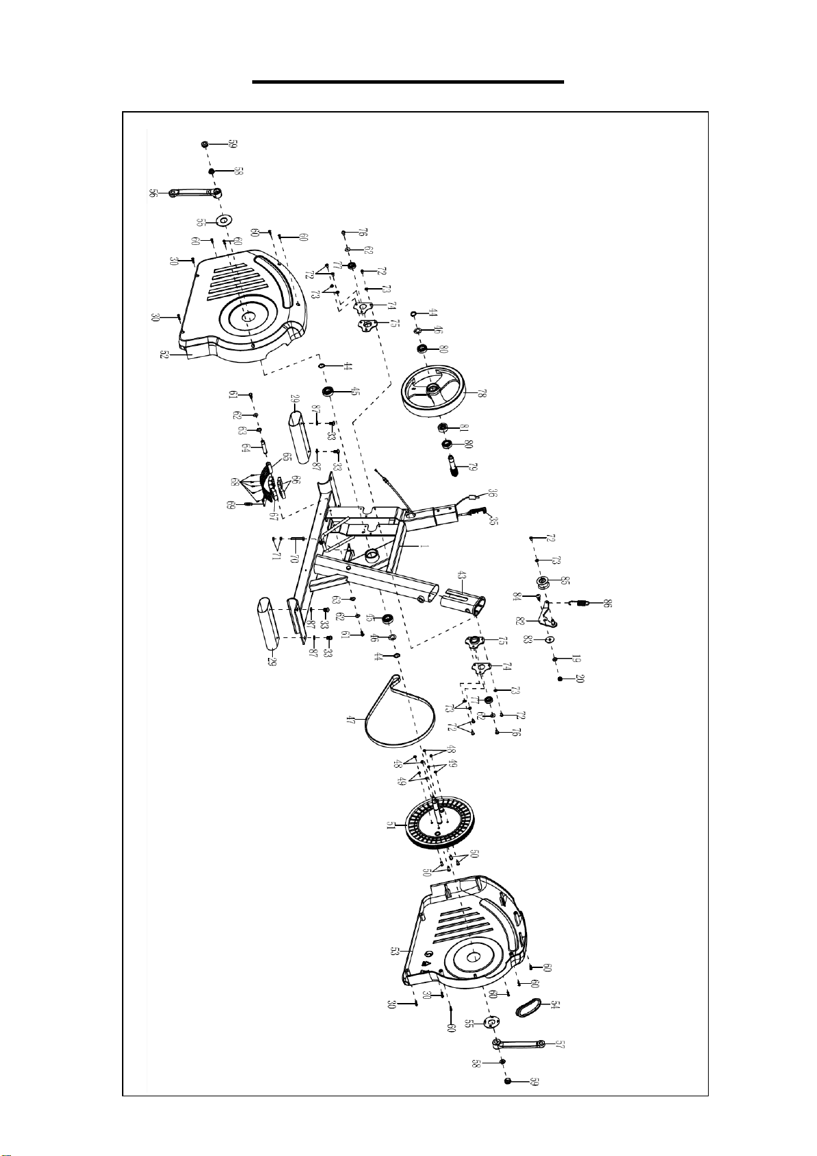
EXPLODED DIAGRAM 2

4
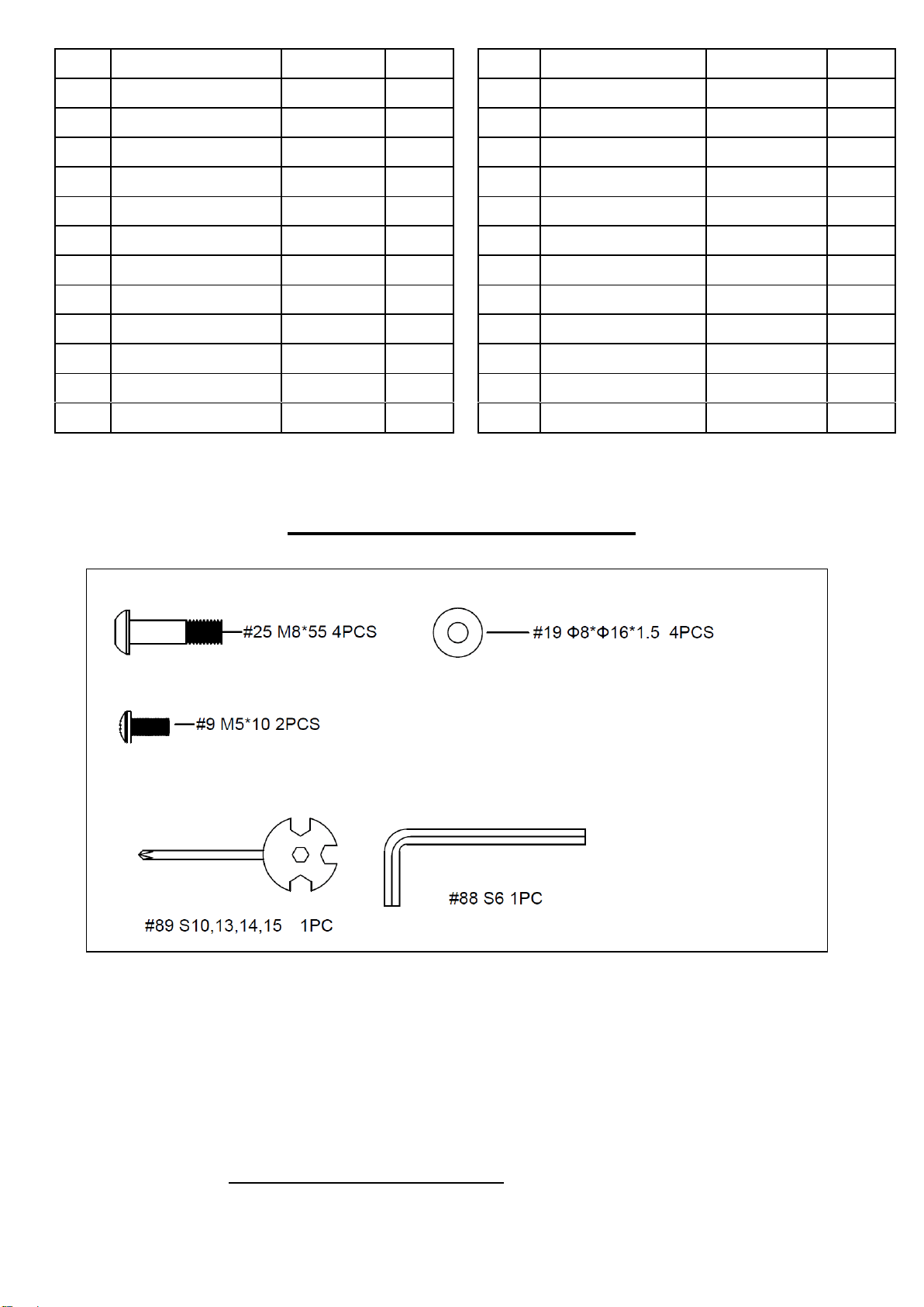
PARTS LIST
No.
Description
Spec.
Qty
No.
Description
Spec.
Qty
1
Main Frame
1
33
Screw
M8*20
10
2
Front Stabilizer
1
34
Big Arc Washer
Ф8*Ф20*2.0
2
3
Rear Stabilizer
1
35
Tension Wire
L=1000mm
1
4
Seat Post
1
36
Sensor Wire
L=750mm
1
5
Seat Slider
1
37
Extension Sensor
Wire
L=800mm
1
6
Handlebar Post
1
38
Decorative Cover
1
7
Handlebar
1
39
Bottle Holder
1
8
Computer
1
40
Tension Control Knob
L=420mm
1
8a
Computer Wire
1
40a
Tension Control Wire
1
9
Screw
M5*10
6
41
Big Arc Washer
Ф5*Ф18*1.0
1
10
Handlebar Foam Grip
Φ24*Φ34*650
2
42
Bolt
M5*55
1
11
End Cap
Φ33
2
43
Seat Post Bushing
1
12
Handle Pulse Sensor
2
44
C-clip
Φ17*1
3
12a
Handle Pulse Wire
L=750mm
1
45
Bearing
6203ZZ
2
13
Screw
ST4.2*20
2
46
Wave Washer
Φ17*Φ21*0.3
2
14
Plug
Ф12.1
1
47
Belt
PJ400
1
15
Spring Washer
Ф8
8
48
Nut
M6
4
16
Screw
M8*30
2
49
Spring Washer
Ф6
4
17
Clamp Cover
1
50
Screw
M6*15
4
18
Seat
1
51
Belt Pulley with
Middle Axle
Φ260
1
19
Washer
Ф8*Ф16*1.5
14
52
Left Belt Cover
1
20
Nut
M8
6
53
Right Belt Cover
1
21
Square End Cap
2
54
Seal Ring
1
22
Big Washer
Ф8*Ф20*2.0
1
55
Crank Cover
2
23
Round Knob
M8*20
1
56
Left Crank
6.5"
1
24
Adjustment Knob
M16*1.5
1
57
Right Crank
6.5"
1
25
Bolt
M8*55
4
58
Nut
M10*1.25
2
26
Bolt
M8*40
2
59
Crank Cap
2
27
Transportation
Wheel
2
60
Screw
ST4.2*25
8
28
Adjustable End Cap
4
61
Screw
M6*15
2
29
Shipping Tube
2
62
Washer
Φ6*Φ16*1.2
4
30
Screw
ST4.2*20
8
63
Shaft Snap Ring
2
31
Left Pedal
JD-22A
1
64
Magnetic Plate Axle
1
32
Right Pedal
JD-22A
1
65
Magnetic Bracket
1
5
No.
Description
Spec.
Qty
No.
Description
Spec.
Qty
66
Magnet
4
78
Flywheel
Ф240
1
67
Magnet Seat
1
79
Flywheel Axle
Ф24*103
1
68
Screw
ST2.9*9
5
80
Bearing
6003
2
69
Spring
Φ15*50
1
81
One Way Bearing
Φ35*Φ17*12
1
70
Bolt
M6*45
1
82
Idler Wheel Shaft
1
71
Nut
M6
2
83
PC Pad
1
72
Screw
M6*10
7
84
Screw
M8
1
73
Washer
Φ6*Φ12*1.0
7
85
Idler Wheel
1
74
Bearing End Cover
2
86
Spring
Φ17*62
1
75
Plastic Bearing Seat
2
87
Plastic Washer
Ф8*Ф20*2.0
4
76
Screw
M6*12
2
88
Allen Wrench
S6
1
77
Bearing
6001
2
89
Spanner
S10,13,14,15
1
HARDWARE PACKAGE
Ordering Replacement Parts (U.S. and Canadian Customers only)
Please provide the following information in order for us to accurately identify the part(s) needed:
✓ The model number (found on cover of manual)
✓ The product name (found on cover of manual)
✓ The part number found on the “EXPLODED DIAGRAM” and “PARTS LIST” (found near the front
of the manual)
Please contact us at [email protected] or 1-877-90SUNNY (877-907-8669).
6
ASSEMBLY INSTRUCTIONS
We value your experience using Sunny Health and Fitness products. For assistance with parts or
(877-907-8669).
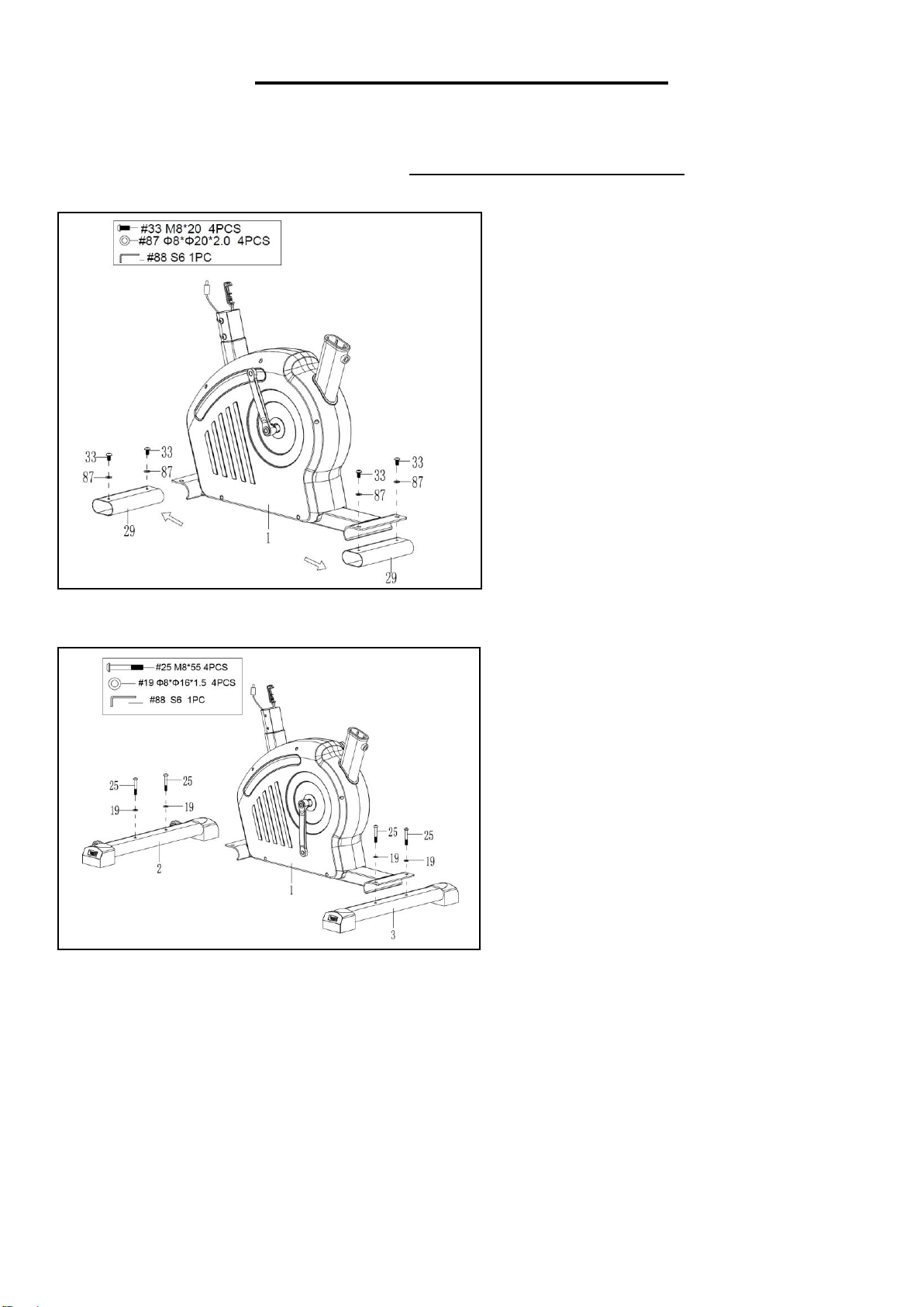
STEP 1:
Unscrew 4 Screws (No. 33) from Main
Frame (No. 1) with Allen Wrench (No.
88). Remove 4 Plastic Washers (No. 87)
and 2 Shipping Tubes (No. 29) from
Main Frame (No. 1).
You may save these parts [Screws (No.
33), Plastic Washers (No. 87), Shipping
Tubes (No. 29)] in case you would like to
repackage and transport this equipment in
the future.
STEP 2:
Attach the Front Stabilizer (No. 2) and
Rear Stabilizer (No. 3) to the Main
Frame (No. 1) with 4 Bolts (No. 25) and 4
Washers (No. 19). Tighten and secure
with the Allen Wrench (No. 88).
7
We value your experience using Sunny Health and Fitness products. For assistance with parts or
troubleshooting, please contact us at support@sunnyhealthfitness.com or 1-877-90SUNNY
(877-907-8669).
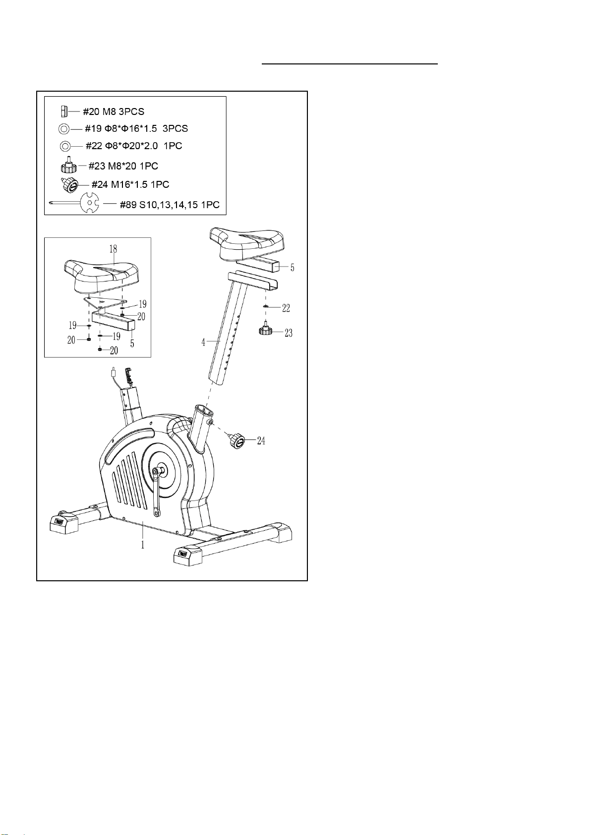
STEP 3:
Remove 3 Nuts (No. 20) and 3 Washers
(No. 19) from Seat (No. 18) using the
Spanner (No. 89).
Attach the Seat (No. 18) to the Seat Slider
(No. 5) with 3 Nuts (No. 20) and 3 Washers
(No. 19) that were removed. Tighten and
secure with Spanner (No. 89).
Remove Round Knob (No. 23) and 1 Big
Washer (No. 22) from Seat Slider (No. 5)
by hand, and then attach the Seat Slider
(No. 5) onto the Seat Post (No. 4) with
Round Knob (No. 23) and 1 Big Washer
(No. 22) that were removed. Tighten and
secure by hand.
Attach the Seat Post (No. 4) onto the Main
Frame (No. 1) with Adjustment Knob (No.
24). Tighten and secure by hand.
8
We value your experience using Sunny Health and Fitness products. For assistance with parts or
(877-907-8669).
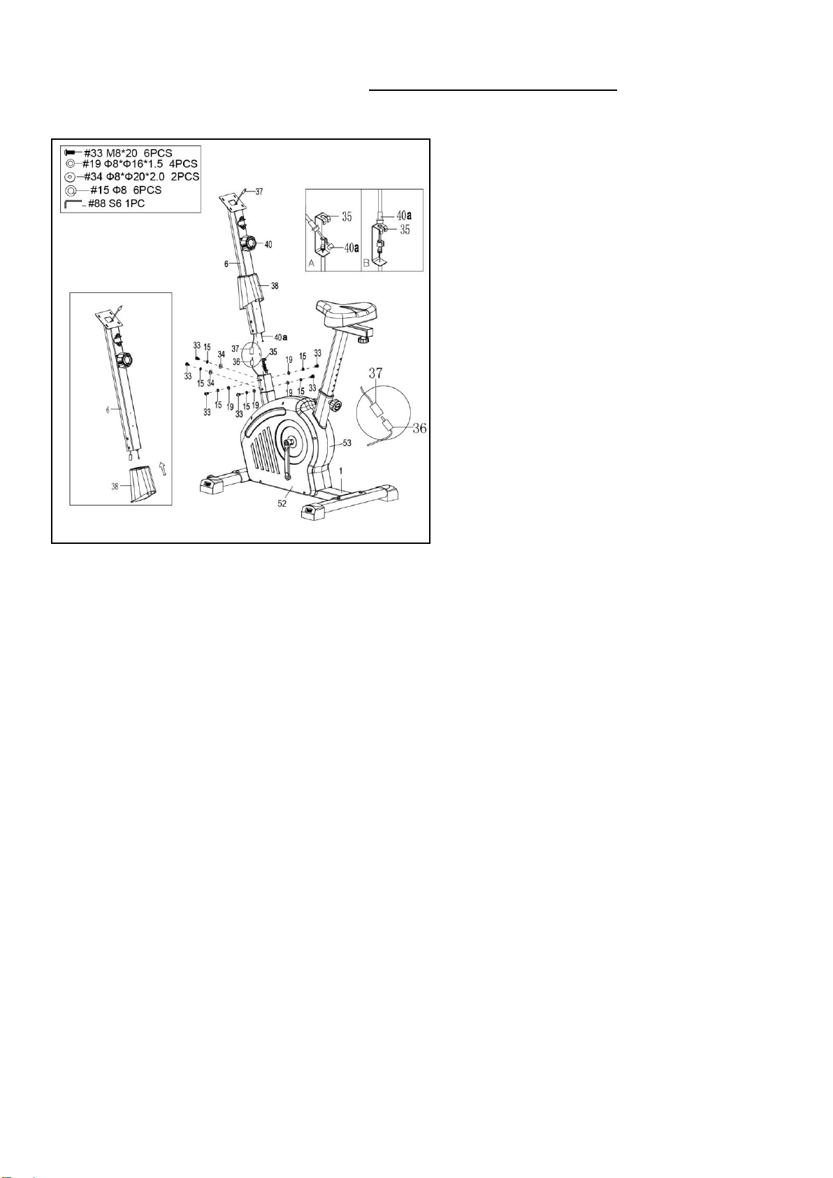
STEP 4:
Remove 6 Screws (No. 33), 2 Big Arc
Washers (No. 34), 4 Washers (No. 19)
and 6 Spring Washers (No. 15) from the
Main Frame (No. 1) with Allen Wrench
(No. 88).
Attach the Decorative Cover (No. 38) into
the Handlebar Post (No. 6)
CAUTION: Please make sure the Tension
Control Knob (No. 40) is at the lowest
resistance level (level 1, all the way to the
left) before you connect any wires together.
Attach the Tension Control Wire (No.
40a) into the metal bracket of Tension
Wire (No. 35) as shown in drawing A.
Then, pull Tension Control Wire (No.
40a) upward and insert it into the slot of
metal bracket of Tension Wire (No. 35) as
shown in drawing B. Make sure the metal
fitting on Tension Control Wire (No. 40a)
is secured in the metal bracket.
Connect the Sensor Wire (No. 36) to the
Extension Sensor Wire (No. 37). Insert
the connecting wires into Handlebar Post
(No. 6).
Attach the Handlebar Post (No. 6) to the
Main Frame (No. 1) with 6 Screws (No.
33), 2 Big Arc Washers (No. 34), 4
Washers (No. 19) and 6 Spring Washers
(No. 15) that were removed. Tighten and
secure with Allen Wrench (No. 88).
Lower the Decorative Cover (No. 38) to fit
in Left and Right Belt Covers (No. 52 &
No. 53).
NOTE: Be careful not to pinch any wires
when attaching Handlebar Post (No. 6) to
Main Frame (No. 1).
9
We value your experience using Sunny Health and Fitness products. For assistance with parts or
(877-907-8669).
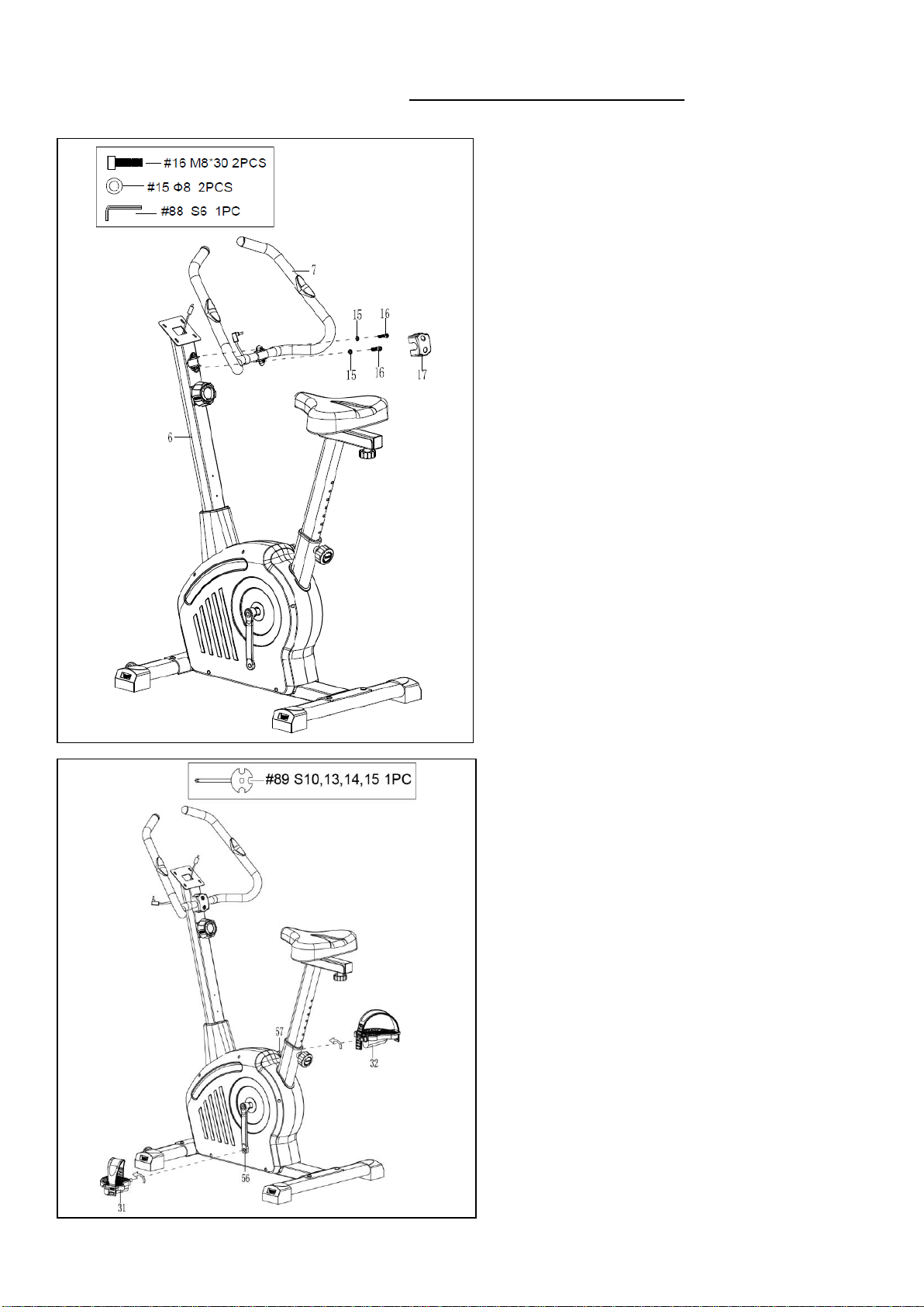
STEP 5:
Remove 2 Screws (No. 16) and 2 Spring
Washers (No. 15) from the Handlebar Post
(No. 6) with Allen Wrench (No. 88).
Attach the Handlebar (No. 7) to the
Handlebar Post (No. 6) with 2 Screws (No.
16) and 2 Spring Washers (No. 15) that
were removed. Tighten and secure with
Allen Wrench (No. 88).
Attach Clamp Cover (No. 17) to the
Handlebar (No. 7) by hand.
STEP 6:
Align Left Pedal (No. 31) with Left Crank
(No. 56) at 90° and gently insert pedal into
the crank arm. Turn the Left Pedal (No. 31)
counter-clockwise as tightly as you can
with your hands, then use Spanner (No. 89)
to tighten securely.
Align Right Pedal (No. 32) with Right
Crank (No. 57) at 90° and gently insert
pedal into the crank arm. Turn the Right
Pedal (No. 32) clockwise as tightly as you
can with your hands, then use Spanner (No.
89) to tighten securely.
10
We value your experience using Sunny Health and Fitness products. For assistance with parts or
(877-907-8669).
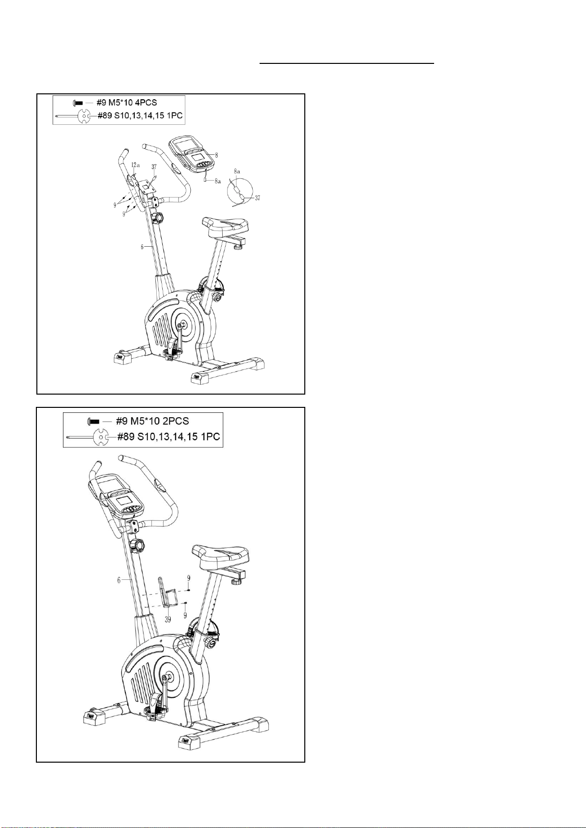
STEP 7:
Remove 4 Screws (No. 9) from the back of
the Computer (No. 8) with the Spanner
(No. 89).
Connect the Extension Sensor Wire (No.
37) to the Computer Wire (No. 8a). Then
insert them into the Handlebar Post (No.
6).
Insert the Handle Pulse Wire (No. 12a)
into the Pulse Input jack on the back of
Computer (No. 8).
Attach Computer (No. 8) to the top end of
the Handlebar Post (No. 6) with 4 Screws
(No. 9) that were removed. Tighten and
secure with Spanner (No. 89).
STEP 8:
Attach Bottle Holder (No. 39) to the
Handlebar Post (No. 6) with 2 Screws
(No. 9) . Tighten and secure with Spanner
(No. 89).
The assembly is complete!
11
BATTERY INSTALLATION & REPLACEMENT
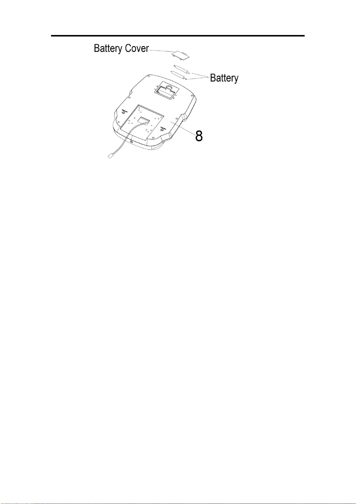
BATTERY INSTALLATION
1. Take out 2 AA batteries from computer box.
2. Press the buckle of battery cover on the Computer (No. 8), then remove battery cover.
3. Install 2 AA batteries into the battery case on the back of the Computer (No. 8). Pay attention to
the battery + and – poles before installing.
4. Press the buckle of battery cover, then put the battery cover back to the back of the Computer
(No. 8).
The installation is complete!
BATTERY REPLACEMENT
1. Press the buckle of battery cover on the back of the Computer (No. 8), then remove battery
cover.
2. Remove the 2 old AA batteries in the battery case and install 2 new AA batteries into the battery
case on the back of the Computer (No. 8). Pay attention to the battery + and – poles before
installing.
3. Press the buckle of battery cover, then put the battery cover back to the back of the Computer
(No. 8).
The replacement is complete!
BATTERY DISPOSAL
Dispose the batteries according to the laws and regulations of your local region. Some batteries
may be recycled. When disposing or recycling, do not mix battery types.
12
ADJUSTMENTS GUIDE
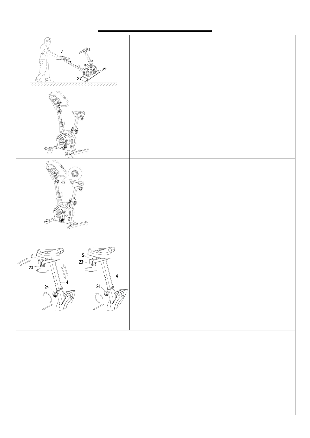
MOVING THE UPRIGHT BIKE
Hold the Handlebar (No. 7) and tilt the bike until the
Transportation Wheels (No. 27) on the front stabilizer
touch the ground. Now you can transport the upright bike
to the desired location with ease.
ADJUSTING THE BALANCE
In order to achieve a smooth and comfortable ride, you
must ensure that the upright bike is stabled and secured.
If you notice that the upright bike is unbalanced during
use, you should adjust the Adjustable End Caps (No. 28)
located on the front and rear stabilizers until the upright
bike becomes levelled with the floor surface.
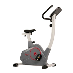
ADJUSTING THE TENSION
Adjust the tension by rotating the Tension Control Knob
(No. 40) clockwise to increase the level of resistance.
Rotate the Tension Control Knob (No. 40)
counter-clockwise to decrease the level of resistance.
Tension levels are set at Level 1 being the lowest and
Level 12 being the highest.
ADJUSTING THE SEAT
Loosen and pull out the Adjustment Knob (No. 24) to
adjust the height of the seat. You may also slide the seat
forward or backwards by loosening the Round Knob (No.
23) on the Seat Slider (No. 5). When adjusting, you will
see a limit on the seat post and seat slider. Do NOT lift the
posts passed this mark. Always check the Adjustment
Knob (No. 24) and Round Knob (No. 23) to ensure that
they are fully secured when you finish making an
adjustment.
CLEANING
The upright bike can be cleaned with a soft, clean and damp cloth. Do not use abrasives or solvents
on plastic parts. Please wipe your perspiration off the upright bike after each use. Be careful not to
get excessive moisture on the computer display panel as this might cause electrical hazard or
electronics to fail. Please keep the upright bike, especially the computer, out of direct sunlight to
prevent screen damage. Please inspect all assembly bolts and pedals on the upright bike for proper
tightness every week.
STORAGE
Store the upright bike in a clean and dry environment, away from children.

13
EXERCISE COMPUTER
FUNCTION BUTTONS:
MODE:
1. Press the button to select hour, minute, year, month and date for setting.
2. Press the button to select TIME, DISTANCE, CALORIES and PULSE to
preset.
3. Press the button to select function displaying on main LCD or enter after
setting.
4. Press the button to confirm setting value of Gender, Age, Height and
Weight.
5. Press the button and hold for 2 seconds to reset all value to zero.
(Replacing batteries will reset all values to ZERO automatically.)
NOTE: If the time, date, and year are not set up in the beginning, you must remove the
batteries and reinsert them to set up these functions. Previous data will not be saved.
SET:
1. Set up the time, year, month and date.
2. Set up the target value of TIME, DISTANCE, CALORIES and PULSE. You can hold the button to
increase the value fast.
3. Set up the personal data of Gender, Age, Height and Weight for Body Fat test.
RESET:
1. Press the button to reset function value when setting.
2. Press the button and hold for 2 seconds to reset all values to ZERO (Replacing batteries will
reset all values to ZERO automatically.).
BODY FAT:
Press this button to enter Body Fat measuring function. Next, press MODE button to enter your
personal data of Gender, Age, Height and Weight. After finished setting, press again to measure
your Body Fat percentage (FAT%) and BMI.
RECOVERY:
To activate the heart rate recovery function after pulse signal. Press any button to return to the main
display.
FUNCTIONS :
SCAN:
Automatically scans through each mode in sequence every 6 seconds. The cycle of functions
showing on display is RPM-SPEED–TIME–DISTANCE–CALORIES-PULSE on the main screen.
TIME:
Accumulates the total time from 00:00 up to 99:59. The user may preset target time by pressing the
SET & MODE buttons. Each increase is 1 minute

14
RPM:
Displays the Rotation per Minute (RPM). The RPM and SPEED will switch to one another on
display, every 6 seconds after exercise starts.
SPEED:
Displays current training speed. Maximum speed is 99.9 MPH (miles/hour).
DISTANCE:
Accumulates total distance from 0.00 up to 99.99 m (miles). The user may preset target distance
data by pressing the SET & MODE buttons, by increments of 0.5 mile.
CALORIES:
Accumulates calories burned during training from 0 to max. 999 calories. The user may also preset
the target calories before training by pressing the SET & MODE buttons, by increments of 10 cal.
PULSE:
Displays the user's heart rate in beats per minute during training. You may set the target heart rate
by pressing the SET & MODE buttons.
NOTE: This data was designed to be a guide for exercise use only and should not be used
for medical purpose.
CALENDAR:
Displays date, month, and year when the computer is in sleep mode.
CLOCK:
Displays current clock time when the computer is in sleep mode.
TEMPERATURE:
Displays current room temperature from 0℉ to 99℉ when the computer is in sleep mode.
OPERATION:
1. Power on – Installs 2 pieces of 1.5V UM-3 or AA batteries. The computer starts the segment
test with a long beeping sound. (When the batteries are removed, all the function values will be
reset to ZERO or default value.)
2. Set current data – Press the SET and MODE buttons to set up current time, year, month, and
date. After the first setting and until the batteries need to be replaced, the preset data will be
updated automatically.
3. Select and preset target value – Get access to the setting function of TIME, DISTANCE,
CALORIES and PULSE. When you are in TIME setting mode, the value will flash and you can
press the SET button to adjust the value. Press the MODE button for confirmation and skip to
next setting. The setting of DISTANCE, CALORIES and PULSE is the same as TIME setting.
4. After entering the speed signal, each function of SPEED-RPM-TIME-DISTANCE-CALORIES-
PULSE will display every 6 seconds.
5. You can press the MODE button to select single function display on the main screen except
RPM & SPEED. The RPM & SPEED function will display every 6 seconds.
6. If you have preset any function targets before, the function starts to count down from the target
when the training starts. Once the target is achieved, the computer will beep, and the function
will count from zero automatically if training continues.
7. Pulse measurement – After holding on two handle pulses in a few seconds, the computer will
show your current heart rate in beats per minute. To ensure the heart rate readout precise,

15
please hold the handle pulses with both hands. You may preset target pulse before training
starts. Once your current heart rate is achieved, the computer will beep to notify you.
8. Recovery – When the PULSE is working, you can press “RECOVERY” button to start the
recovery test function. The computer will count down from 0:60 seconds to 0:00 and the
heartbeat symbol will flash until the countdown reaches “0:00”. For the 60 seconds counting
period, please keep both hands on the handle pulses. The screen will display “F1 to F6” to show
your recovery status. F1 is the best, and the F6 is the worst. You may keep exercising to
improve your heart rate recovery status, and check it by using Recovery function.
9. Body Fat -
9-1. Press BODY FAT button to enter body fat measurement.
9-2. Press MODE and SET buttons to input your personal data. Each personal data available is
described as the following:
GENDER: (Male), (Female) AGE: 10 ~ 99 years HEIGHT: 100 ~ 250 cm (or
3’03” ~ 8’02“) WEIGHT: 10 ~ 200 kg (or 22 ~ 440 lbs)
9-3. After all personal data have been entered, you can press BODY FAT button and hold on
handle pulses to start the body fat testing.
9-4. It takes a few seconds to test the body fat. If you did not hold onto the handle pulses during
the test procedure, the LCD will show the error code Err after 10 seconds period.
9-5. After testing is finished, you will see a percentage and BMI figure (Body Mass Index)
displayed on the main LCD in sequence by scan mode.
BODY FAT % : Calculate from your personal data to show the value from 5%~50%.
BMI : Calculate from your personal data to show the value from 1.0~99.99.
9-6. Press any button to return to the main display.
Note:
1. If training stops for 4 minutes, the screen will show room temperature, clock, and calendar
display automatically.
2. If the computer did not receive any speed signal or button input for one minute, the LED
backlight will turn off automatically. Any speed signal input or button input can turn on the LED
backlight automatically.
3. If the computer display is abnormal, please re-install the batteries and try again.
4. Battery Spec: 1.5V UM-3 or AA (2PCS).
APP CONNECTION
1. Scan below QR code to enter the app store and download the Sunny Health & Fitness app to
your mobile phone.
2. Press the Bluetooth switch to connect. Then you can use the app through your mobile
phone.

16
TROUBLESHOOTING
PROBLEM
SOLUTION
There is no display on the computer.
1. Remove the computer and verify that the
wire from the computer is properly
connected to the wire that comes from the
handlebar post.
2. Check if the batteries are correctly
positioned and battery springs are in proper
contact with batteries.
3. The batteries in the computer may be
unresponsive. Change to new batteries.
The upright bike wobbles when in use.
Turn the adjustable end caps on the front and
rear stabilizers as needed to level the upright
bike.
The upright bike makes squeaking noise
when in use.
Some bolts on the upright bike might have
become loose. Please inspect all the bolts and
tighten any loosened bolts.
Version 1.0