Loading ...
Loading ...
Loading ...
40
INSTALLATION
INSTALLATION OF THE APPLIANCE
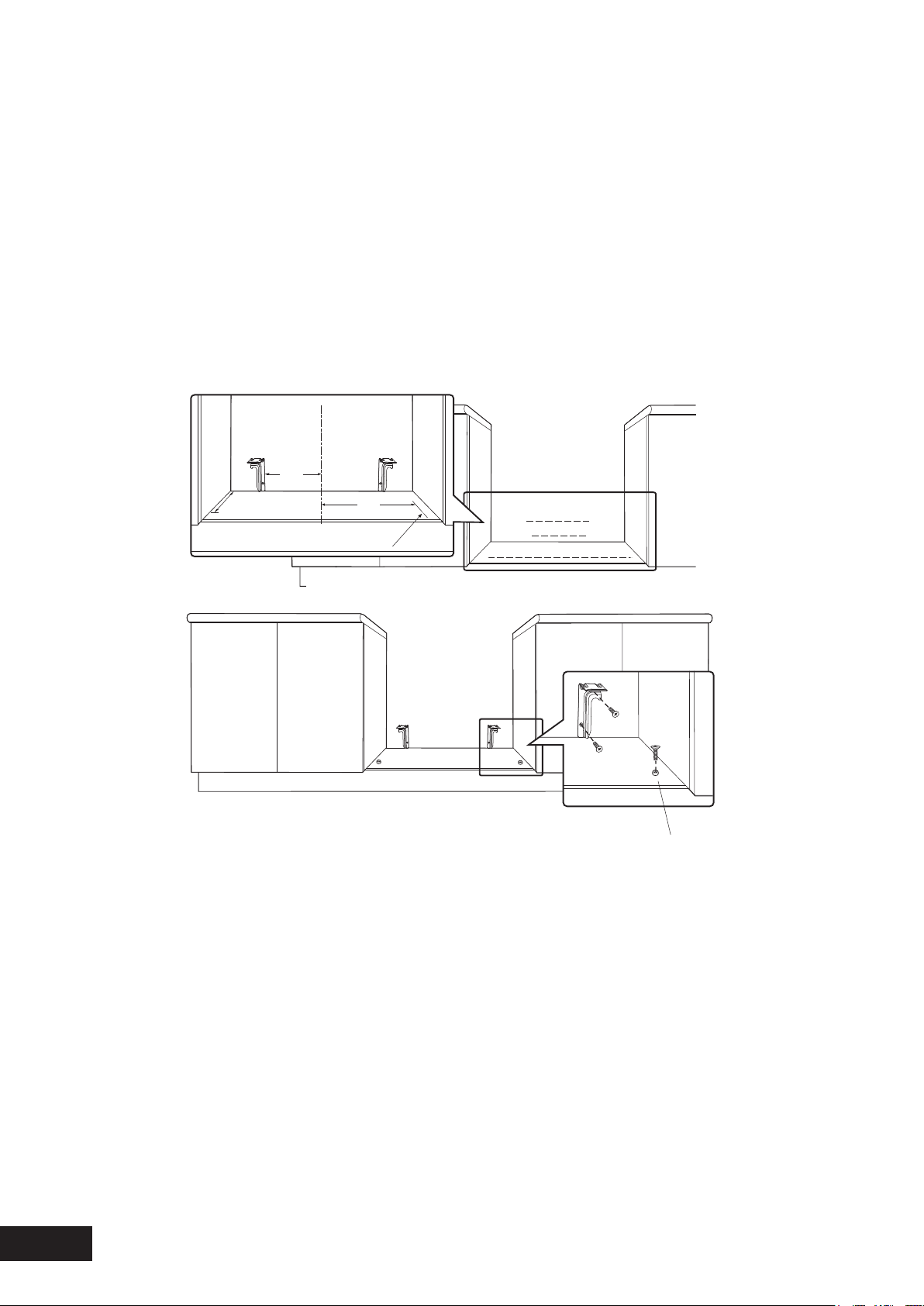
INSTALLATION OF ANTI-TILT BRACKETS AND STOPS
•Thebracketsaretobesecuredtothebackwallwith
appropriatefasteners.
•Thebottomedgeofthethebracketsrestonthe
horizontalsupportsurface.
•Twostopsaretobescrewedtotheplinthinlocations
asshown(stopsprovided).Thestopslocateintoslotsin
thebaseoftheappliancetopreventtheproductfrom
beingpulledforwardwheninstalled.
•Measurementsfromtherearwallaretobeadjustedif
therearetilesetc.thatcomebetweentheappliance
andthewall.
•Onceservicesareconnected,productcanbelifted
ontotheplinthandpushedbackcarefully,ensuringthe
applianceengagesintobothbracketsattherearand
thefrontstops.
•Iftheproductrequiresremovalforservice,itmustbe
liftedatthefrontapproximately5mmtoclearthefront
stopspriortobeingpulledforward.
+
+
+
+
+
+
+
+
Location of
holes for front stops
Measurements are to be adjusted to account for the thickness of any skirting
board or tiles coming between the back of the appliance and the wall.
4
7
5
C
L
414
183
INSTALLATION SEQUENCE FOR FLOOR MOUNTED
OR SLOT IN INSTALLATION
•Checkthattherequiredservicesarecorrectly
positioned(seeelectrical&gasservicesrequirements)
•Ensurecabinetryhasthecorrectdetails
•Installanti-tiltbracketsandchainhookorfrontstops
asappropriate
•Removeallpackagingfromcooker,removeallloose
partsie.Trivets,burnercrowns,ovenshelves.
•Removeplasticfilmfromcooker.
•Fitsplashbacktocooker
•Slidecookerintopositiontocheckfitmenttoanti-tilt
bracket.Forfloormountedinstallation,checktheheight
andlevelofthecooker.Adjustcookerfeetasrequired.
•Connectgasandelectricalservices
•Placeintoposition
•CompleteCertificateofCompliance.
183
414
475
Locationofholesforfrontstops
Measurementsaretobeadjustedtoaccountforthethicknessofanyskirting
boardortilescomingbetweenthebackoftheapplianceandthewall
Frontstops
SLOT-IN INSTALLATION (continued)
Loading ...
Loading ...
Loading ...