Loading ...
Loading ...
Loading ...
— 22 —
Assembly
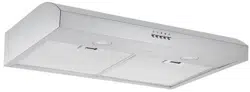
Circuit Diagram
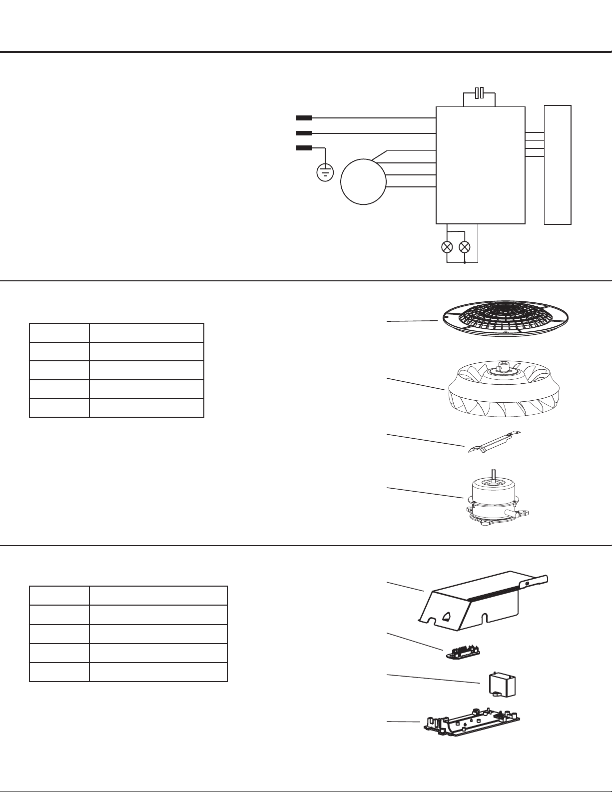
Blower Assembly
Electrical Assembly
Number Part
1 Junctionboxcover
2 Main PCB board
3 Capacitor
4 Junctionboxbottom
Number Part
1 Blower cover
2 Impeller
3 Trunking
4 Motor
Main PCB
L
N
E
M
Push Button
Cap acito r
AC 120V 60Hz
4
3
2
1
4
3
2
1
4
3
2
1
1258
1275
4
3
2
1
4
3
2
1
4
3
2
1
1258
1275
u
v
w
x
u
v
w
x
Loading ...
Loading ...
Loading ...