Loading ...
Loading ...
Loading ...
— 12 —
Installation
STEP 6
Preparations
NOTE: To avoid damage to your hood, prevent debris from entering the vent opening.
• Determine and mark the centre line on the ceiling or wall where the range hood will be installed.
• Make sure there is proper clearance within the ceiling or wall for exhaust vent.
• Duetotheweightandsizeofthisunit,pleasemakesurethatthesupportsystemorframeworkbeingusedisstableand
secure in the ceiling or wall.
• Put a thick, protective covering over counter top, cook top or range to protect from damage or dirt.
• Removeanyhazardousobjectsaroundtheareawheninstalling.
CAUTION
If moving the cooking range is necessary to install the hood, turn OFF the power on an electric range at the main
electrical box. SHUT OFF THE GAS BEFORE MOVING A GAS RANGE.
STEP 7
Create Exterior Ventilation (New Installation Only)
• Choose one of the exterior venting methods shown on Page 11.
• Create the exterior ventilation hole.
• Following recommendations and calculations specied on Pages 10 to 11, use new aluminum/metal ducting cut
specically for the distance between the range hood damper and the exterior damper.
• Fasten all connections with sheet metal screws and tape all joints with certied aluminum or foil tape.
• Please check the building codes in your city to learn which tape product is recommended.
STEP 8
Electrical Connection
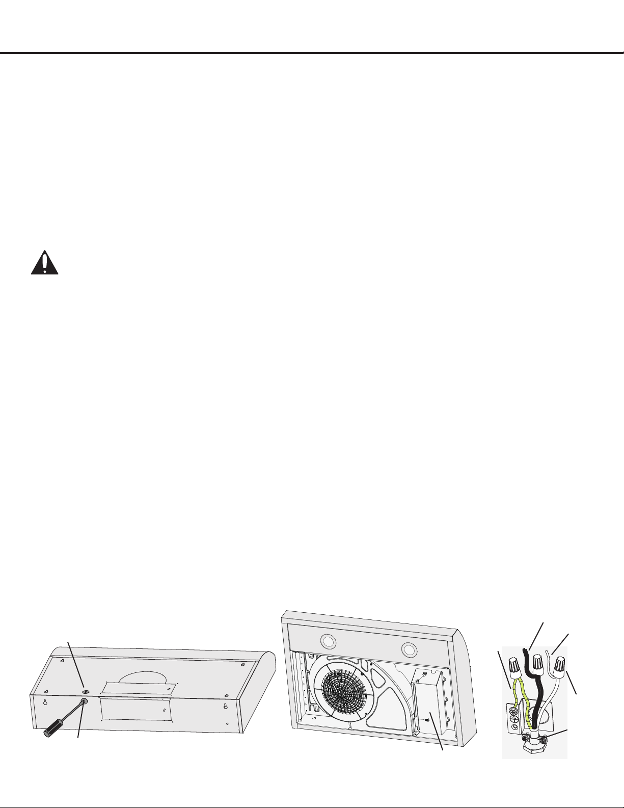
• Use a tool to punch the wiring hole, from the two options for holes. Please choose hole A or hole B accordingly to wiring
requirement (Figure 1). Install a 1/2 in. diameter strain relief (not included) through the power cable knockout.
• Loosen two screws of junction box, and remove the junction box cover (Figure 2). Connect cable to range hood wiring
using included wire connectors. Connect BLACK to BLACK, WHITE to WHITE and GREEN or BARE WIRE to GREEN
ground screw. DO NOT FORGET TO CONNECT THE GROUND (Figure 3).
Figure 1 Figure 2 Figure 3
A
B
Live wire
(black)
Neutral wire
(white)
Earth wire
(yellow/
green)
Wire
connectors
Cable
gland
Junctionboxcover
Loading ...
Loading ...
Loading ...