Loading ...
Loading ...
Loading ...
6
Note
The range of lens adjustment angle: horizontal (0°~+360°), vertical (0°~+78°), image rotation
direction (0°~+360°).
As for the device shown in Figure 2-4, loosen the adjusting screw and pull the enclosure
downward to separate pedestal from enclosure, finally the device is taken apart.
Note
The range of lens adjustment angle: horizontal (0°~+360°), vertical (0°~+78°), image rotation
direction (0°~+360°).
Step 3
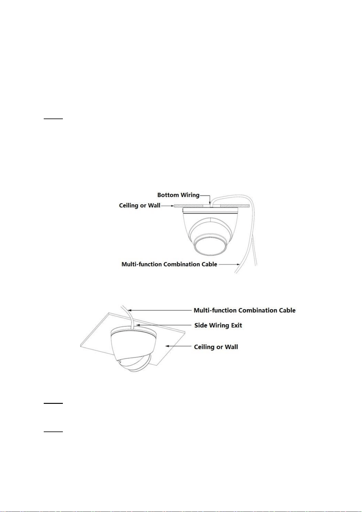
Select bottom cabling or side cabling; lead the multi-function cable into the cable exit hole on the
mounting surface.
Bottom cabling: select to lead out the cable through the mounting surface, which can protect the
cable effectively.
Side cabling: select to lead out the cable through side exit and add metal conduit and etc., which
can prevent the cable from being destroyed.
Figure 2-6
Figure 2-7
Step 4
Adjust pedestal position, aim at bottom hole. Take out self-tapping screws in accessories bag. Insert
them into the bottom holes of plastic expansion bolt and fix the pedestal on the mounting surface.
Step 5
Assemble the device.
As for the device shown in Figure 2-2, install the enclosure back to pedestal; rotate the enclosure
clockwise to complete device assembly.
Loading ...
Loading ...
Loading ...