
HD IR Network Dome Camera Quick Start Guide

i
Welcome
Thank you for purchasing our network cameras.
This user’s manual is designed to be a reference tool for using your product.
Please read the following safeguards and warnings carefully before you use this series product.
Please keep this user’s manual well for future reference.
Important Safeguards and Warnings
Electrical safety
All installation and operation should conform to your local electrical safety codes.
The power source shall conform to the requirement of the Safety Extra Low Voltage (SELV)
standard, and supply power with rated voltage which conforms to Limited power Source
requirement according IEC60950-1. Please note that the power supply requirement is subject to
the device label.
Make sure the power supply is correct before operating the device.
A readily accessible disconnect device shall be incorporated in the building installation wiring
Prevent the power cable from being trampled or pressed, especially the plug, power socket and the
junction extruded from the device.
We assume no liability or responsibility for all the fires or electrical shock caused by improper
handling or installation.
Environment
Do not aim the device at strong light to focus, such as lamp light and sun light, otherwise it might
cause over brightness or light marks, which are not the device malfunction, and affect the longevity
of Charge Coupled Device (CCD) or Complementary Metal-Oxide Semiconductor (CMOS).
Do not place the device in a damp or dusty environment, extremely hot or cold temperatures, or the
locations with strong electromagnetic radiation or unstable lighting.
Keep the camera away from water or other liquid to avoid damages to the internal components.
Keep the indoor device away from rain or damp to avoid fire or lightning.
Keep sound ventilation to avoid heat accumulation.
Transport, use and store the device within the range of allowed humidity and temperature.
Heavy stress, violent vibration or water splash are not allowed during transportation, storage and
installation.
Pack the device with standard factory packaging or the equivalent material when transporting the
device.
The device needs to be installed in the location where professional staff can cover (professionals
need to know the attentions of using the device), non-professionals are not allowed to enter device
installation area when the device is operating normally, which may cause accidental damage.

ii
Operation and Daily Maintenance
Do not directly touch the heat dissipation component of the device to avoid scald.
Do not dismantle the device because there is no component that can be fixed by users themselves.
Otherwise, it might cause water leakage or bad image due to unprofessional dismantling.
Please contact after-sale service to replace desiccant when it becomes green. (The desiccant is
not provided by default)
It is recommended to use the device together with lightning arrester to improve lightning protection
effect.
It is recommended to get the grounding holes to be grounded to enhance the reliability of the
device.
Do not directly touch the optic component CCD or CMOS. You can use the air blower to blow away
the dust or dirt on the lens surface. Please use a dry cloth wetted by alcohol to wipe away the dust
gently if necessary.
Use the dry soft cloth to clean the device. If the dust is difficult to be removed, please wipe it away
with a clean cloth wetted slightly by the mild detergent, and then use the dry cloth to clean the
device. Do not use volatile solvents like alcohol, benzene, thinner, or strong detergent with
abrasiveness, otherwise it will damage the surface coating or reduce the working performance of
the device.
When installing or using the device, do not directly touch or wipe the surface of the dome cover
because it is an optical device. If stained with dirt, use oil-free soft brush or air blower to gently
wipe it away. If stained with grease or fingerprint, use soft cloth to gently wipe the water drop or oil
and wait till it is dry, and then use oil-free cotton cloth or lens cleaning paper soaked with alcohol or
detergent to wipe from the lens center outward till it is clean.
We are not liable for any problems caused by unauthorized modification or attempted repair.
The dome cover is a kind of optical component, please do not touch or wipe the cover surface
during installation and application, it may stain dust, grease or fingerprint, you can use absorbent
cotton to dip some diethyl ether or use soft cloth to dip some water and then wipe gently. You can
also use air gun to remove the dust if the cover is stained with dust.
Warnings
Please strengthen the protection of network, device data and personal information, adopt
necessary measures of guarantee device network security, including but not limited to using strong
password, modifying password regularly, upgrading firmware to the latest version, isolating
computer network and so on. For the IP camera firmware of some old version, the ONVIF
password won’t be modified automatically after the main password of the system is modified. You
need to upgrade the camera firmware or upgrade the ONVIF password manually.
Please modify the default password after login to avoid being stolen.
Use the standard components provided by manufacturer and make sure the device is installed and
fixed by professional engineers.
The surface of the image sensor should not be exposed to laser beam radiation in an environment
where a laser beam device is used.

iii
Do not provide two or more power supply sources for the device; otherwise it might damage the
device.
Disclaimer
This manual is for reference only. Please refer to the actual product for more details.
Minor differences might be found in user interface, and there might be deviation between the actual
value of some data and the value provided in the manual due to the reasons such as the real
environment is not stable. Please refer to the final explanation of the company if there is any doubt
or dispute.
All the designs and software are subject to change without prior written notice. The manual will be
regularly updated according to the product upgrade without prior announcement.
Please contact the supplier or customer service if there is any problem occurred when using the
device.
Please contact the customer service for the latest procedure and supplementary documentation.
Please visit our website or contact your local service engineer for more information.
The company is not liable for any loss caused by the operation that does not comply with the
manual.
If there is any uncertainty or controversy, please refer to our final explanation.
Regulatory Information
FCC Information
1.1 FCC conditions:
This device complies with part 15 of the FCC Rules. Operation is subject to the following two conditions:
This device may not cause harmful interference
This device must accept any interference received, including interference that may cause
undesired operation.
1.2 FCC compliance:
This equipment has been tested and found to comply with the limits for a digital device, pursuant to part
15 of the FCC Rules. These limits are designed to provide reasonable protection against harmful
interference. This equipment generate, uses and can radiate radio frequency energy and, if not installed
and used in accordance with the instruction manual, may cause harmful interference to radio
communication. However, there is no guarantee that interference will not occur in a particular
installation. If this equipment does cause harmful interference to radio or television reception, which can
be determined by turning the equipment off and on, the user is encouraged to try to correct the
interference by one or more of the following measures:
Reorient or relocate the receiving antenna.
Increase the separation between the equipment and receiver.
Connect the equipment into an outlet on a circuit different from that to which the receiver is
connected.
Consult the dealer or an experienced radio/TV technician for help.

iv
Note
Please refer to the disk for more details, check and download the corresponding user’s manual and
tool.
Before installation, please open the package and check all the components are included.
Contact your local retailer as soon as possible if something is broken in your package.
Accessory Name
Amount
Accessory Name
Amount
Network Camera Unit
1
Installation Position Map
1
Quick Start Guide
1
Waterproof Connector
1
Screw Package
1
CD
1
Wrench (Optional)
1

v
Table of Contents
1 Device Structure ......................................................................................................................... 1
1.1 Structure Components ................................................................................................. 1
1.2 Framework and Dimension ......................................................................................... 2
2 Device Installation ...................................................................................................................... 3
2.1 Fix Device ...................................................................................................................... 3
2.2 Connect Device Cable ................................................................................................. 7
3 Network Configuration ............................................................................................................... 7
3.1 Device Initialization ...................................................................................................... 8
3.2 Modify IP Address ........................................................................................................ 9
3.3 Login WEB Interface .................................................................................................. 10
1
1 Device Structure
1.1 Structure Components
Note
The following figures are for reference only, which are used to know each structure component
and cable port functions.
Different devices may have different structures and cables, please refer to the following figures
according to the actual product.
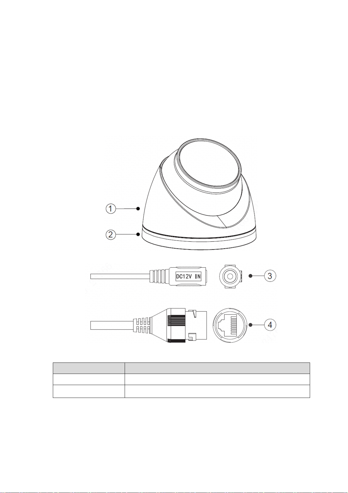
You can refer to the following figures for multiple-function combination cable information. See Figure
1-1and Figure 1-2.
Figure 1-1
Figure 1-2
Please refer to Table 1-1for detailed information about structure appearance.
Component
Component Name
1
Dome enclosure
2
Dome pedestal
Table 1-1
Please refer to Table 1-2for detailed information about cable port.
2
SN
Port
Port Name
Connector
Function Description
3
DC 12V
12V DC power
-
Connect to DC 12V power, input
power. Be sure to power the
device according to the instruction
of device label.
Caution
It may cause damage to the
device if it fails to power the
device according to the instruction
of device label.
4
LAN
Network port
Ethernet
port
Connect to standard Ethernet
cable.
Note
Some devices don’t support PoE
power supply.
Table 1-2
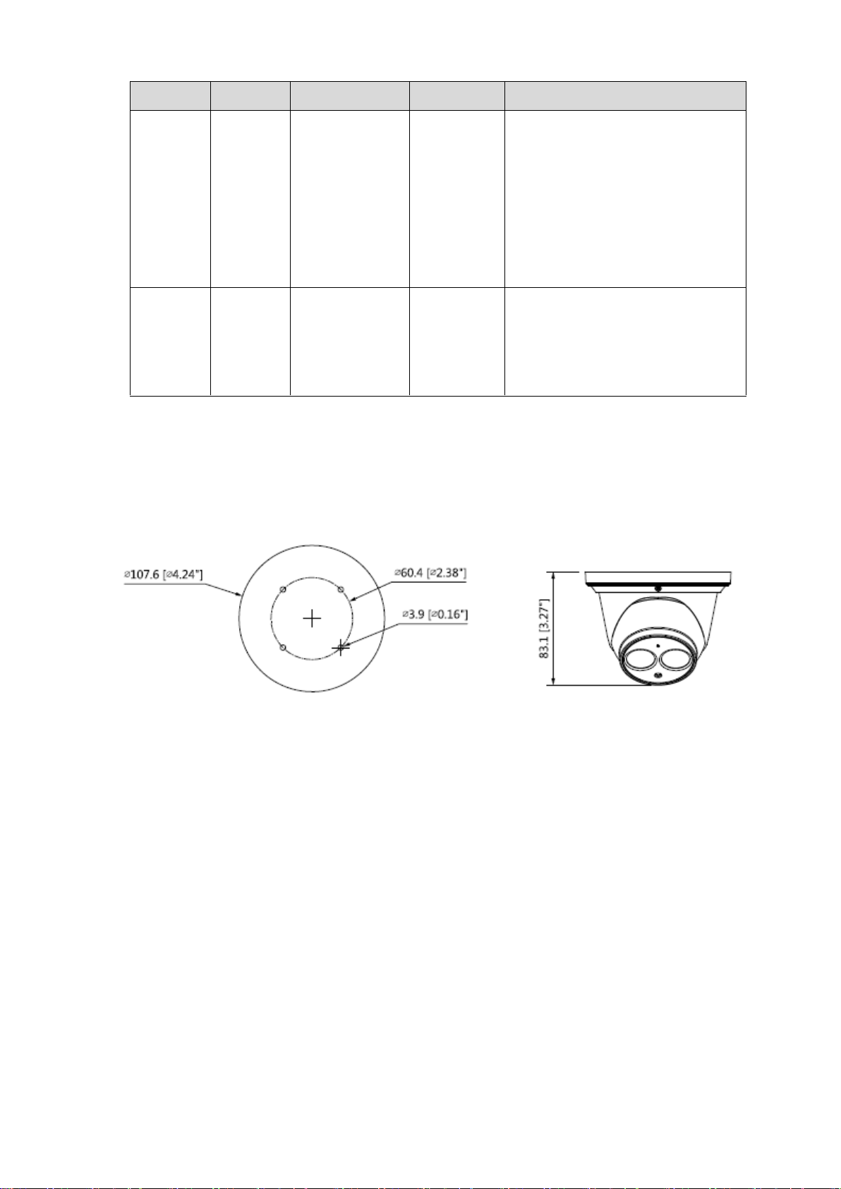
1.2 Framework and Dimension
Note
The following figures are for reference only, which are used to know the device dimension, please
refer to Figure 1-3 according to the actual product.
Figure 1-3
3
2 Device Installation
2.1 Install SD Card (Optional)
Note
Please cut off the device power before installing SD card.
Some devices are not equipped with SD card slot; please refer to the actual device for more
details.
Please install SD card when the device is equipped with SD card slot and it needs to use SD card.
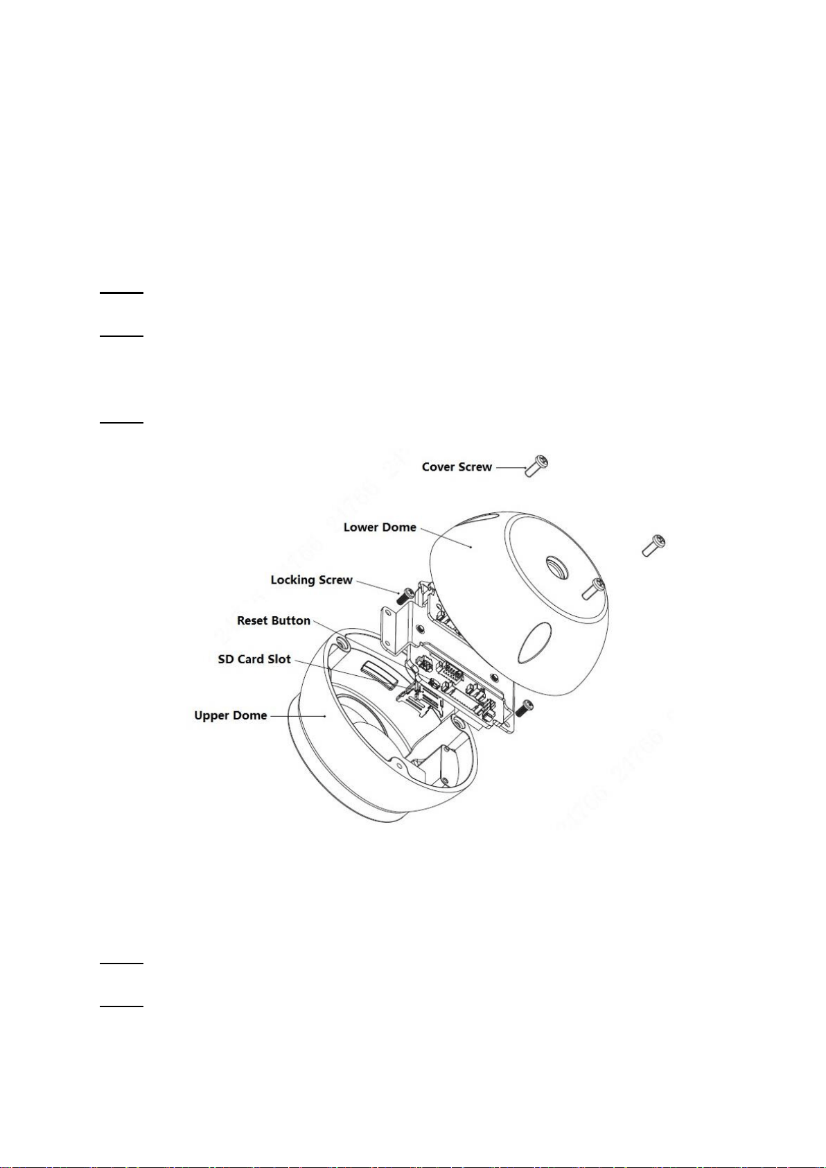
Step 1
Dismantle the device enclosure, loosen the screws on the lower dome and then open the dome body.
Step 2
Loosen the locking screws and take out the camera module from the upper dome.
SD card slot and reset button are shown in Figure 2-1, the installation figure is for reference only,
please refer to the actual product for more details.
Step 3
Open SD card slot; install the SD card into the slot and close the SD card slot cover.
Figure 2-1
Note
Press the reset button for 5s to 10s continuously when the device is running normally, and then the
system config info will be restored to factory default settings.
Step 4
Tighten the locking screws and install the camera module back to upper dome.
Step 5
Use cover screws to tighten the dome body firmly and then install the device enclosure back to place.
2.2 Fix Device
5
Figure 2-4
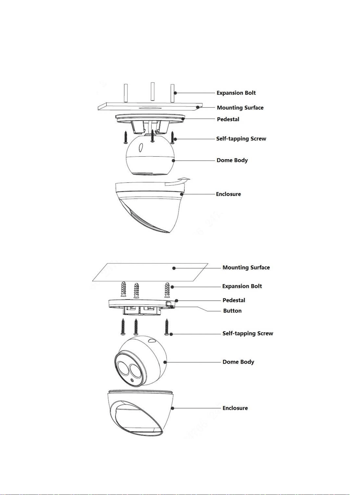
Step 1
Please take out the installation position map from the accessories bag, and then stick it on the
mounting surface, dig bottom holes according to the installation position map, and then put the
expansion bolts into the bottom holes and lock them firmly.
Step 2
Dismantle the device.
As for the device shown in Figure 2-2, rotate the enclosure anticlockwise and then dismantle the
device.
Note
The range of lens adjustment angle: horizontal (0°~+360°), vertical (0°~+90°), image rotation
direction (0°~+360°).
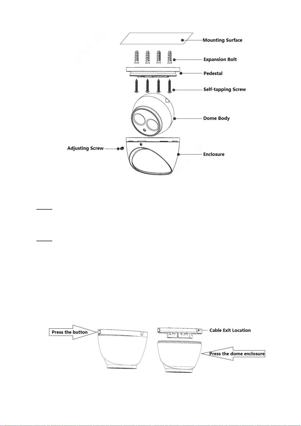
AS for the device shown in Figure 2-3, the steps of dismantling device are shown as follows.
1. Press the button on the pedestal to make it expand.
2. Press the dome enclosure down the cable exit to separate the pedestal from the dome enclosure
and disassemble the device.
Figure 2-5
6
Note
The range of lens adjustment angle: horizontal (0°~+360°), vertical (0°~+78°), image rotation
direction (0°~+360°).
As for the device shown in Figure 2-4, loosen the adjusting screw and pull the enclosure
downward to separate pedestal from enclosure, finally the device is taken apart.
Note
The range of lens adjustment angle: horizontal (0°~+360°), vertical (0°~+78°), image rotation
direction (0°~+360°).
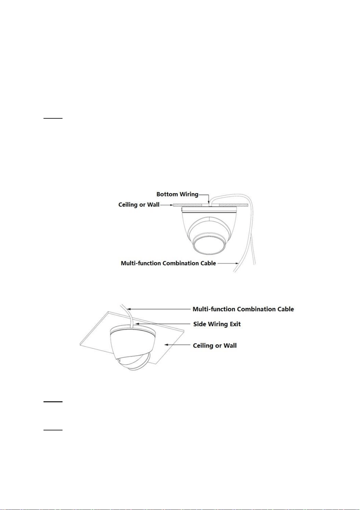
Step 3
Select bottom cabling or side cabling; lead the multi-function cable into the cable exit hole on the
mounting surface.
Bottom cabling: select to lead out the cable through the mounting surface, which can protect the
cable effectively.
Side cabling: select to lead out the cable through side exit and add metal conduit and etc., which
can prevent the cable from being destroyed.
Figure 2-6
Figure 2-7
Step 4
Adjust pedestal position, aim at bottom hole. Take out self-tapping screws in accessories bag. Insert
them into the bottom holes of plastic expansion bolt and fix the pedestal on the mounting surface.
Step 5
Assemble the device.
As for the device shown in Figure 2-2, install the enclosure back to pedestal; rotate the enclosure
clockwise to complete device assembly.
7
As for the device shown in Figure 2-3, install the enclosure back to pedestal; push the enclosure
upward to complete device assembly.
As for the device shown in Figure 2-4, install the enclosure back to pedestal; push the enclosure
upward and tighten the adjusting screw firmly to complete device assembly.
2.3 Connect Device Cable
It is to connect device power cable and network cable.
Note
It needs to implement the operation when the device is equipped with waterproof connector and it is
used outdoors.
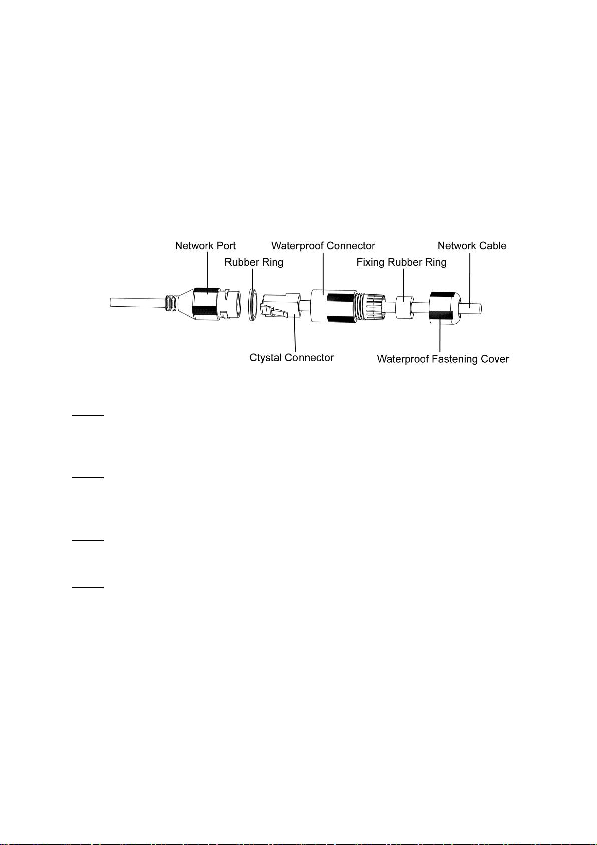
Figure 2-8
Step 1
Keep the convex groove outward and install the rubber ring into the network port, keep the smaller
hole of the rubber ring outward and install the fixing rubber ring into the main body of the waterproof
connector.
Step 2
Pull the network cable without crystal head through main body of waterproof connector, fixing rubber
ring and waterproof locking cover, make the crystal head of network cable, and then insert it into the
network cable.
Step 3
Put the main body of waterproof connector on the network port and rotate it clockwise to lock the
network port and waterproof connector firmly.
Step 4
Put the waterproof locking cover on the main body of waterproof connector and rotate it clockwise to
lock the waterproof connector and waterproof locking cover firmly.
8
3 Network Configuration
You can initialize the device and modify IP address via "Quick Configuration Tool", for Wi-Fi network
camera, it needs to connect to wired network to configure Wi-Fi parameters; You can also initialize
device and modify IP address on the WEB interface. Please refer to the WEB Operation Manual in the
disk for more details.
Note
It needs to implement initialization if it is the first time use device or the device is restored to
factory default. Only some device support initialization function.
It can implement initialization only when the device IP address (192.168.1.108 by default) and the
IP address of PC are in the same network segment.
In order to make the camera have access to network smoothly, please plan available IP segment
according to the actual network environment.
The following figures are for reference only; different models may have different interfaces.
3.1 Device Initialization
Step 1
Double click "IP ConfigTool.exe" and open quick config tool.
Step 2
Click to enter the interface where you can modify IP address, click Search Setting, the system
will display the Setting dialog box.
Step 3
Set the device network segment, login user name and password, and then click OK. The system will
display the searched devices after searching completes.
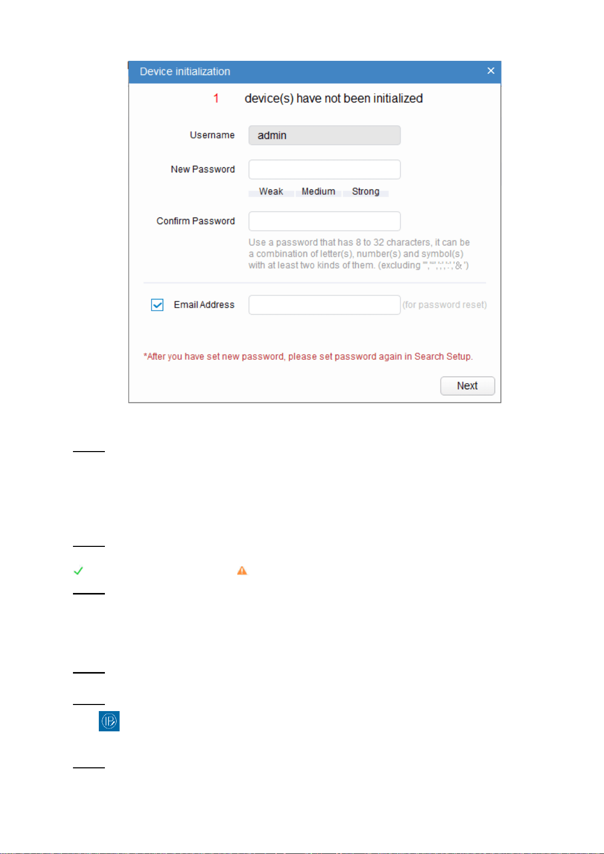
Step 4
Select the devices which need initialization and click Initialization. The system will display the
interface of Device Initialization, which is shown in Figure 3-1.
9
Figure 3-1
Step 5
Set new password and confirm password, select Email Address and input email address.
Note
The password can be set as 8 to 32 characters; it can be a combination of number(s), letter(s) and
symbol(s) with at least two kinds of them (excluding “'”,“"”,“;”,“:”,“&”). Please set password with high
security according to the password strong and weak prompt.
Step 6
Click Initialization, the system begins to initialize the device.
means initialization succeeded; means initialization failed. Click the icon to check more details.
Step 7
Click OK to complete device initialization.
3.2 Modify IP Address
Step 1
Double click "IP ConfigTool.exe" and open quick config tool.
Step 2
Click to enter the interface where you can modify IP address, click Search Setting, the system
will display the Setting dialog box.
Step 3
10
Set the device network segment, login user name and password, and then click OK. The system will
display the searched devices after searching completes.
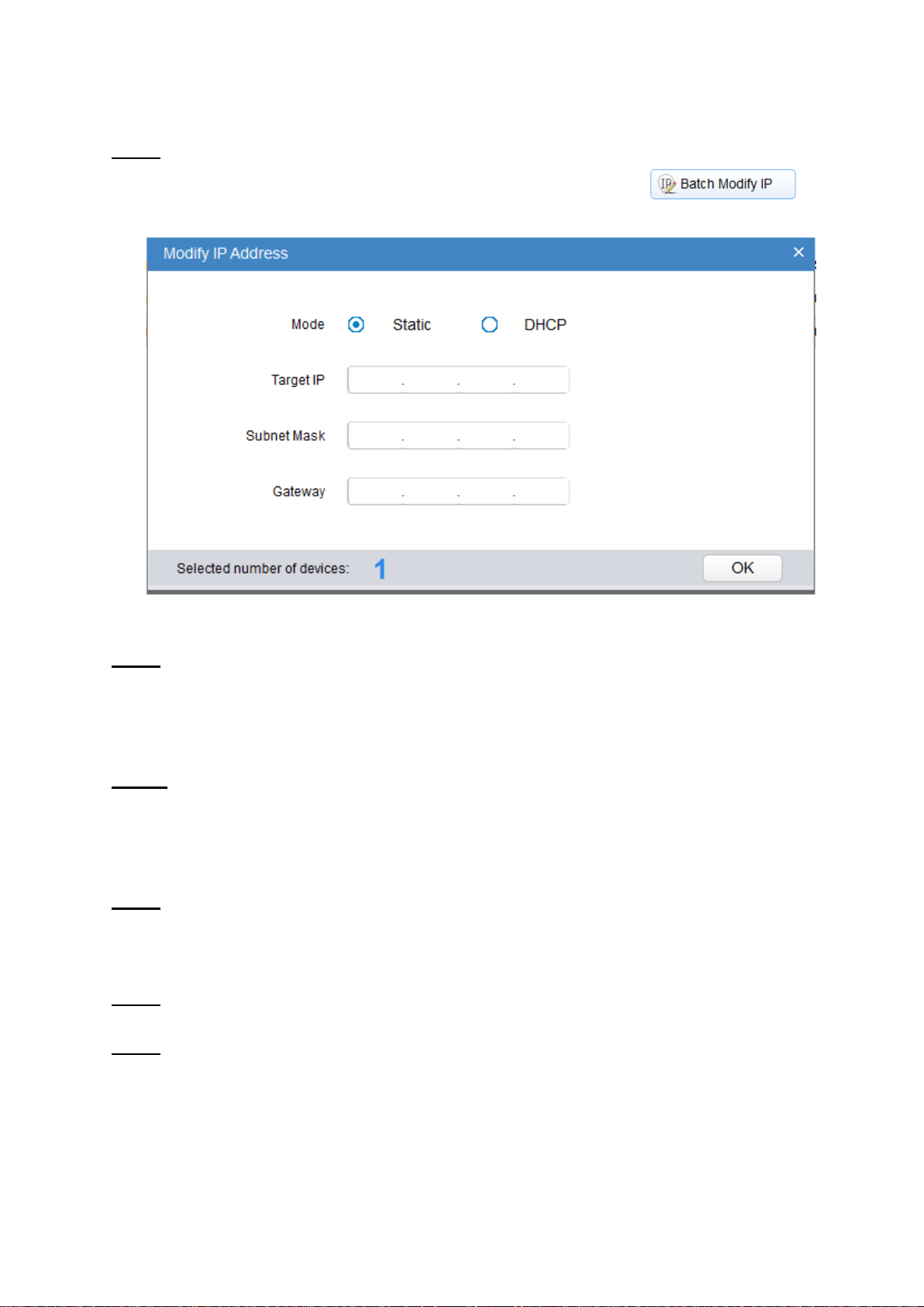
Step 4
Select the devices whose IP addresses need to be modified, and then click . The
system will display the dialog box of Modify IP Address, which is shown in Figure 3-2.
Figure 3-2
Step 5
Set the mode as Static, and enter the planned start IP, subnet mask and gateway.
Note
Set the mode as DHCP when there is DHCP server in the network, the device will automatically
acquire IP address from the DHCP server.
Step 6
Click OK to complete modification of device IP address.
3.3 Login WEB Interface
Step 1
Open IE browser, enter the modified camera IP address into the address bar and then press Enter
button. Please operate according to the interface prompt if the interface displays guide of Software
License Agreement and Online Upgrade.
Step 2
Enter username and password, click Login.
Step 3
For the first login, click Click Here to Download Plug-in, install controls according to system prompt.
The main interface will be shown in Figure 3-3 after control installation is completed.
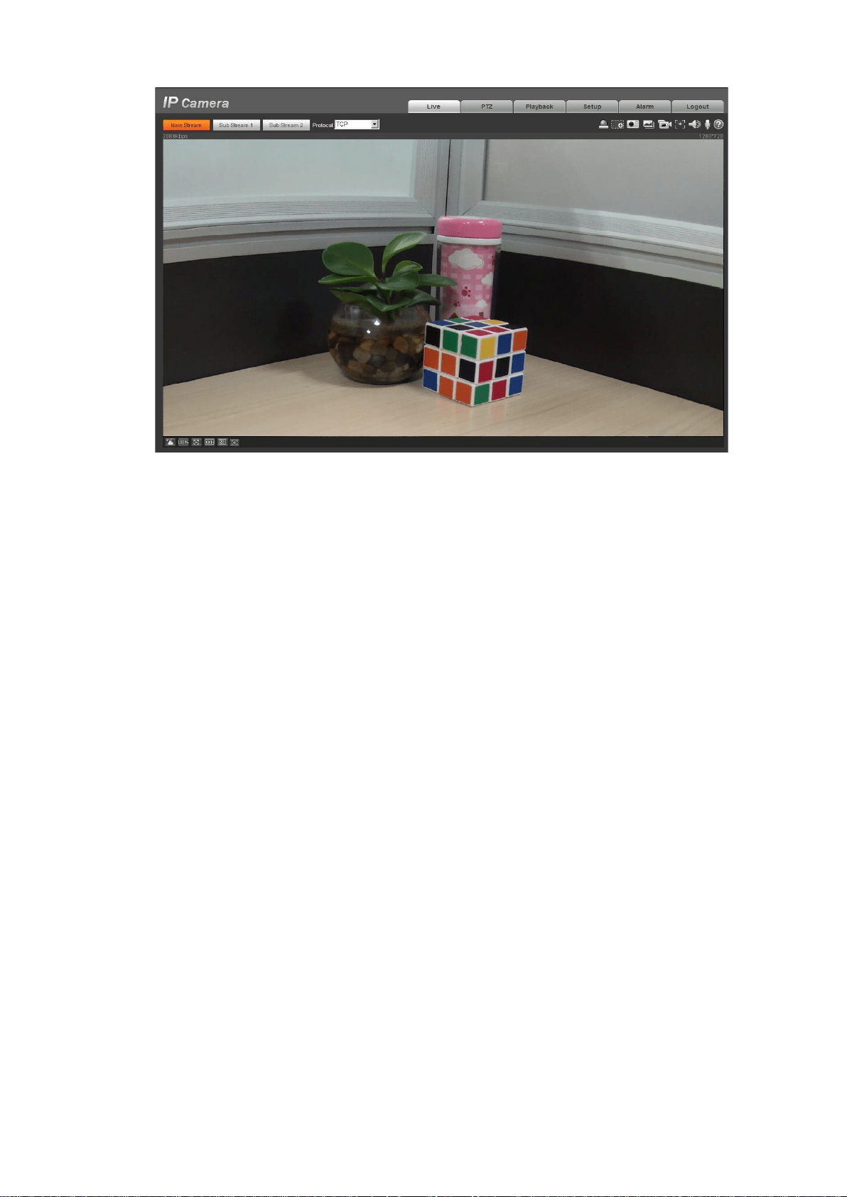
11
Figure 3-3