
Loading ...
Loading ...
Loading ...
ENGLISH
13
6. To remove the wheel, grasp and turn the backing
pad and sanding pad while depressing the spindle
lockbutton.
Mounting and Removing Hubbed
Wheels (Fig. J)
WARNING: Failure to properly seat the flange/ clamp
nut/ wheel could result in serious injury (or damage to
the tool or wheel).”
Hubbed wheels install directly on the 5/8"-11 threaded
spindle. Thread of accessory must match thread ofspindle.
1. Remove backing flange by pulling away fromtool.
2. Thread the wheel on the spindle
4
byhand.
3. Depress the spindle lock button
3
and use a wrench to
tighten the hub of thewheel.
4. Reverse the above procedure to remove thewheel.
Fig. J
3
4
NOTICE: Failure to properly seat the wheel before
turning the tool on may result in damage to the tool
or thewheel.
Mounting Wire Cup Brushes and
WireWheels
CAUTION: To reduce the risk of personal injury,
wear work gloves when handling wire brushes
and wheels. They can becomesharp.
CAUTION: To reduce the risk of damage to the
tool, wheel or brush must not touch guard
when mounted or while in use. Undetectable
damage could occur to the accessory, causing wires to
fragment from accessory wheel orcup.
Wire cup brushes or wire wheels screw directly on the
grinder spindle without the use of flanges. Use only wire
brushes or wheels provided with a 5/8"-11 threaded hub.
A Type 27 guard is required when using wire brushes
andwheels.
1. Thread the wheel on the spindle byhand.
2. Depress spindle lock button and use a wrench on the
hub of the wire wheel or brush to tighten thewheel.
3. To remove the wheel, reverse the aboveprocedure.
NOTICE: To reduce the risk of damage to the tool,
properly seat the wheel hub before turning the toolon.
OPERATION
WARNING: To reduce the risk of serious personal
injury, turn unit off and remove the battery pack
before making any adjustments or removing/
installing attachments or accessories. An
accidental start-up can causeinjury.
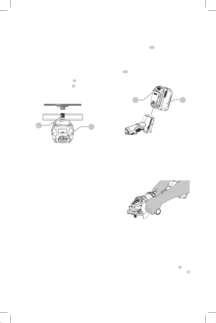
Installing and Removing the Battery Pack
(Fig. K)
NOTE: For best results, make sure your battery pack is
fullycharged.
To install the battery pack
11
into the tool handle, align the
battery pack with the rails inside the tool’s handle and slide
it into the handle until the battery pack is firmly seated in
the tool and ensure that it does notdisengage.
To remove the battery pack from the tool, press the release
button
12
and firmly pull the battery pack out of the tool
handle. Insert it into the charger as described in the charger
section of thismanual.
Fig. K
11 12
Proper Hand Position (Fig. L)
WARNING: To reduce the risk of serious personal injury,
ALWAYS use proper hand position as shown.
WARNING: To reduce the risk of serious personal
injury, ALWAYS hold securely in anticipation of a
suddenreaction.
Proper hand position requires one hand on the main handle
and one hand on the side handle.
Fig. L
Trigger Switch and Lock-off Lever (Fig.M)
WARNING: Before using the tool, check that the side
handle is tightenedsecurely.
WARNING: Hold the side handle and main handle of
the tool firmly to maintain control of the tool at start
up and during use and until the wheel or accessory
stops rotating. Make sure the wheel has come to a
complete stop be fore laying the tooldown.
1. To turn the tool on, push the lock-off lever
2
toward the
back of the tool, then depress the trigger switch
1
. The
tool will run while the switch isdepressed.
2. Turn the tool off by releasing the releasingswitch.
WARNING: Allow the tool to reach full speed before
touching tool to the work surface. Lift the tool from the
work surface before turning the tooloff.
Loading ...
Loading ...
Loading ...