
Loading ...
Loading ...
Loading ...
ENGLISH
11
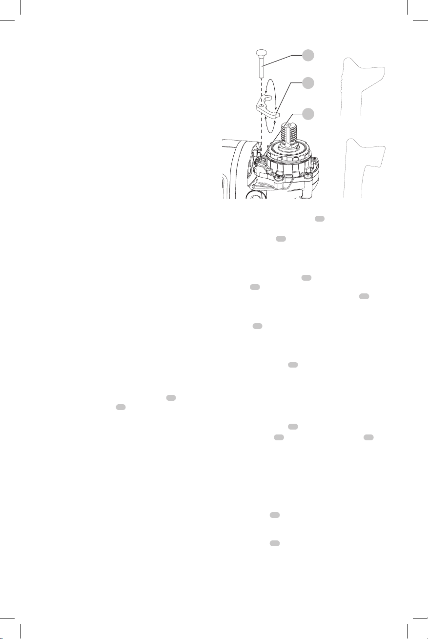
NOTE: If the gear case and motor housing become
separated by more than 1/8" (3.17 mm), the tool must
be serviced and re-assembled by a
DEWALT
service
center. Failure to have the tool serviced may motor and
bearingfailure.
3. Reinstall screws to attach the gear case to the motor
housing. Tighten screws to 12.5 in.-lbs. torque.
Overtightening could cause screws tostrip.
Guards
CAUTION: Guards must be used with all grinding
wheels, cutting wheels, sanding flap discs,
wire brushes, and wire wheels. The tool may
be used without a guard only when sanding with
conventional sanding discs. Refer to Figure A to see
guards provided with the unit. Some applications may
require purchasing the correct guard from your local
dealer or authorized servicecenter.
NOTE: Edge grinding and cutting can be performed with
Type 27 wheels designed and specified for this purpose;
1/4" (6.35 mm) thick wheels are designed for surface
grinding while thinner Type 27 wheels need to be examined
for the manufacturer's label to see if they can be used for
surface grinding or only edge grinding/cutting. A Type 1/41
guard must be used for any wheel where surface grinding
is forbidden. Cutting can also be performed by using a
Type1/41 wheel and a Type 1/41guard.
NOTE: See the Accessories Chart to select the proper guard
/ accessorycombination.
Adjusting and Mounting Guard (Fig. F, G)
CAUTION: Turn unit off and unplug the tool before
making any adjustments or removing or installing
attachments oraccessories.
CAUTION: BEFORE operating the tool, identify which
guard adjustment option your tool is set to.
Adjustment Options
For guard adjustment, the guard release lever
10
engages
one of the alignment holes
17
on the guard collar using
a ratcheting feature. Your grinder offers two options for
thisadjustment.
• One-touch
TM
: In this position the engaging face
is slanted and will ride over to the next alignment
hole when guard is rotated in a clockwise direction
(spindle facing user) but self-locks in the counter-
clockwisedirection.
• Two-touch
TM
: In this position the engaging face is
straight and squared off. It will NOT ride over to the next
alignment hole unless guard release lever is pressed
and held while simultaneously rotating the guard in
either a clockwise or counterclockwise direction (spindle
facinguser).
One Touch
Two Touch
Fig. F
14
10
13
Setting Guard Adjustment Options
To adjust the guard release lever
10
for desired
adjustmentoption:
1. Remove screw
14
using a T20bit.
2. Remove the guard release lever taking note of the
spring position. Choose the end of the lever for the
desired adjustment option. One-touch will use the
slanted end of the lever
10
to engage the alignment
holes
17
on the guard collar. Two-touch will use the
squaredend to engage the alignmnet holes
17
on the
guardcollar.
3. Replace the lever, positioning the chosen end under the
spring
13
. Ensure the lever is in proper contact with
thespring.
4. Replace screw and torque to 2.0-3.0N-m. Ensure proper
installation with spring return function by depressing
guard release lever
10
.
Mounting Guard (Fig. G)
CAUTION: Prior to mounting guard, ensure the screw,
lever, and spring are fitted correctly before mounting
theguard.
1. With the spindle facing the operator, press and hold the
guard release lever
10
.
2. Align the lugs
15
on the guard with the slots
16
on
the gearcase.
3. Push the guard down until the guard lugs engage and
rotate them in the groove on the gear case hub. Release
the guard releaselever.
4. To position the guard:
One-touch
TM
: Rotate the guard clockwise into the
desired working position. Press and hold the guard
release lever
10
release lever to rotate the guard in the
anti-clockwisedirection.
Two-touch
TM
: Press and hold the guard
release lever
10
. Rotate the guard clockwise or
counterclockwise into the desired working position.
NOTE: The guard body should be positioned between
the spindle and the operator to provide maximum
operatorprotection.
Loading ...
Loading ...
Loading ...