
Loading ...
Loading ...
Loading ...
ENGLISH
12
The guard release lever should snap into one of the
alignment holes
17
on the guard collar. This ensures
that the guard issecure.
5. To remove the guard, follow steps 1–3 of these
instructions inreverse.
Fig. G
17
16
15
10
Flanges and Wheels
WARNING: To reduce the risk of serious personal
injury, turn unit off and remove the battery pack
before making any adjustments or removing/
installing attachments or accessories. An
accidental start-up can causeinjury.
Mounting Non-Hubbed Wheels (Fig. H)
WARNING: Failure to properly seat the flange/ clamp
nut/ wheel could result in serious injury (or damage to
the tool or wheel).”
CAUTION: Included flanges must be used with
depressed center Type 27 grinding wheels and
Type1/41 and Type 27/42 cutting wheels. See the
Accessories Chart for moreinformation.
WARNING: A closed, two-sided cutting wheel guard
is re quired when using cutting wheels.
Cutting wheels include diamond wheels and abrasive
discs. Abrasive cutting wheels for metal and concrete
use are available. Diamond blades for concrete cutting
can also beused.
CAUTION: Included flanges must be used with
all non-hubbed accessories except conventional
sandingdiscs.
WARNING: Use of a damaged flange or guard or
failure to use proper flange and guard can re sult in
injury due to wheel breakage and wheel contact. See
the Accessories Chart for moreinformation.
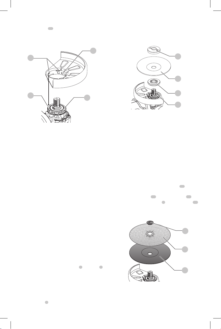
1. Install the unthreaded backing flange
7
on spindle
4
with the raised section (pilot) facing the wheel
asshown.
2. Place wheel against the backing flange, centering the
wheel on the raised section (pilot) of the backingflange.
3. While depressing the spindle lock button and with the
hex depressions facing away from the wheel, thread the
locking flange
8
on spindle so that the lugs engage the
two slots in thespindle.
4. While depressing the spindle lock button, tighten the
locking flange with awrench.
5. To remove the wheel, depress the spindle lock button
and loosen the threaded locking flange with awrench.
Fig. H
8
6
7
4
Mounting Sanding Backing Pads
(Fig.A,I)
NOTE: Use of a guard with sanding discs that use backing
pads, often called fiber resin discs, is not required. Since a
guard is not required for these accessories, the guard may or
may not fit correctly ifused.
WARNING: Failure to properly seat the flange/ clamp
nut/ wheel could result in serious injury (or damage to
the tool or wheel).
WARNING: Proper guard must be reinstalled for
grinding wheel, cutting wheel, sanding flap disc,
wire brush or wire wheel applications after sanding
applications arecomplete.
1. Remove the innerflange.
2. Place or appropriately thread backing pad
18
on
thespindle.
3. Place the sanding disc
19
on the backing pad
18
.
4. While depressing spindle lock
3
, thread clamp nut
20
on spindle, piloting the raised hub on the clamp nut
into the center of san ding disc and backingpad.
Fig. I
20
19
18
5. Tighten the clamp nut by hand. Then depress the
spindle lock button while turning the sanding disc until
the sanding disc and clamp nut aresnug.
Loading ...
Loading ...
Loading ...