
Loading ...
Loading ...
Loading ...
ENGLISH
10
the battery pack after use, avoid placing the charger or
battery pack in a warm environment such as in a metal
shed or an uninsulatedtrailer.
3. If the battery pack does not charge properly:
a. Check operation of receptacle by plugging in a lamp
or other appliance;
b. Check to see if receptacle is connected to a light
switch which turns power off when you turn out the
lights;
c. Move the charger and battery pack to a location
where the surrounding air temperature is
approximately 65°F – 75°F (18° – 24°C);
d. If charging problems persist, take the tool, battery
pack and charger to your local servicecenter.
4. The battery pack should be recharged when it fails to
produce sufficient power on jobs which were easily
done previously. DO NOT CONTINUE to use under these
conditions. Follow the charging procedure. You may also
charge a partially used pack whenever you desire with
no adverse effect on the batterypack.
5. Foreign materials of a conductive nature such as, but
not limited to, grinding dust, metal chips, steel wool,
aluminum foil, or any buildup of metallic particles
should be kept away from charger cavities. Always
unplug the charger from the power supply when there
is no battery pack in the cavity. Unplug the charger
before attempting toclean.
6. Do not freeze or immerse the charger in water or any
otherliquid.
Storage Recommendations
1. The best storage place is one that is cool and dry, away
from direct sunlight and excess heat orcold.
2. For long storage, it is recommended to store a fully
charged battery pack in a cool dry place out of the
charger for optimalresults.
NOTE: Battery packs should not be stored completely
depleted of charge. The battery pack will need to be
recharged beforeuse.
SAVE THESE INSTRUCTIONS FOR
FUTURE USE
Intended Use
These heavy-duty small angle grinders have been designed
for professional grinding, sanding, wire brush, and cut-off
applications at various work sites (i.e., construction sites).
DO NOT use under wet conditions or in presence of
flammable liquids orgases.
These heavy-duty small angle grinders are professional
power tools. DO NOT let children come into contact with
the tool. Supervision is required when inexperienced
operators use thistool.
E-Clutch™
This unit is equipped with an E-Clutch™ (Electronic Clutch),
which in the event of a high-load the unit will be shut off to
reduce the reaction torque to the user. The switch needs to
be cycled (turned on and off) to restarttool.
Kickback Brake™
When a pinch, stall, or bind-up event is sensed the
electronic brake engages with maximum force to quickly
stop the wheel, reduce the movement of the grinder, and
shut the grinder off. The switch needs to be cycled (turned
on and off) to restart thetool.
Power-OFF™ OVERLOAD Protection
The power supply to the motor will be reduced in case
of motor overload. With continued motor overload, the
tool will shut off. The switch needs to be cycled (turned
on and off) to restart tool. The tool will power off each
time the current load reaches the overload current value
(motor burn-up point). If continued overload shutdowns
occur, apply less force/weight on the tool until the tool will
function without the overloadengaging.
Electronic Soft Start
This feature limits the initial start up speed, allowing the tool
to build up to full speed gradually over a 1 secondperiod.
ASSEMBLY AND ADJUSTMENTS
WARNING: To reduce the risk of serious personal
injury, turn unit off and remove the battery pack
before making any adjustments or removing/
installing attachments or accessories. An
accidental start-up can causeinjury.
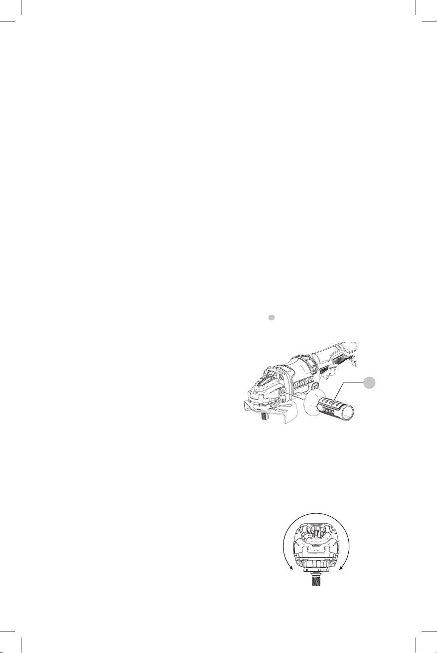
Attaching Side Handle (Fig. D)
The side handle
5
can be fitted to either side of the gear
case in the threaded holes. Before using the tool, check that
the handle is tightenedse cure ly.
Fig. D
5
Rotating the Gear Case (Fig. E)
To improve user comfort, the gear case will rotate 90° for
cuttingoperations.
1. Remove the four corner screws attaching the gear case
to motorhousing.
2. Without separating the gear case from motor housing,
rotate the gear case head to desiredposition.
90˚
90˚
Fig. E
Loading ...
Loading ...
Loading ...