CRAFTSMAN®I
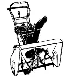
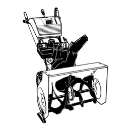
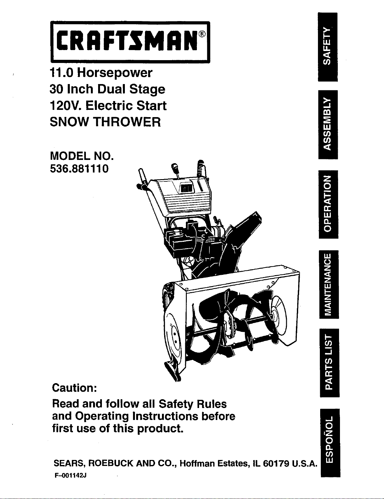
1.0 Horsepower
30 Inch Dual Stage
120V. Electric Start
SNOW THROWER
MODEL NO.
536.881110
Caution:
Read and follow all Safety Rules
and Operating Instructions before
first use of this product.
SEARS, ROEBUCK AND CO., Hoffman Estates, IL 60179 U.S.A.
F--001142J
WARRANTY STATEMENT ......
SAFETY RULES ...............
INTERNATIONAL SYMBOLS ....
ASSEMBLY ...................
OPERATION ..................
MAINTENANCE ...............
SERVICE AND ADJUSTMENT...
2 STORAGE .................... 31
2 TROUBLE SHOOTING CHART .. 32
4 REPAIR PARTS ................ 33
7
13 ENGINE REPAIR PARTS ........ 50
20 SPANISH (ESPAI_IOL) .......... 60
23 PARTS ORDERING/SERVICE ., 92
LIMITED TWO-YEAR WARRANTY ON CRAFTSMAN SNOW THROWER
For twoyears from the date of purchase, when this Craftsman Snow thrower ismaintained,
lubricated, and tuned up according to the operating and maintenance instructions in the
owner's manual, Sears will repair, free of charge, any defect in material or workmanship.
If this Craftsman Snow thrower is used for commercial or rental purposes, this warranty ap-
plies for only 90 days from the date of purchase.
This warranty does not cover the following:
•Items which become worn during normal use, such as spark plugs, drive belts and shear
pins.
•Repay"necessary because of operator abuse or negligence, including bent crankshafts
and the failure to maintain the equipment according to the instructionscontained in the
owner's manual.
WARRANTY SERVICE IS AVAILABLE BY RETURNING THE CRAFTSMAN SNOW
THROWERTO THE NEAREST Sears SERVICE CENTER/DEPARTMENT IN THE
UNITED STATES. THIS WARRANTY APPLIES ONLY WHILE THIS PRODUCT IS IN USE
IN THE UNITED STATES.
This warranty gives you specific legal rights,and you may also have other rights which may
vary from state to state.
Sears, Roebuck and Co., D817WA, Hoffman Estates. IL 60179
Engine Exhaust, some of its constituents, and
certain vehicle components contain or emit
chemicals known to the State of California to
cause cancer and birth defects or other repro-
ductive harm.
Battery posts, terminals and related accessories
contain lead and lead compounds, chemicals
known to the State of California to cause cancer
and birth defeCts or other reproductive harm.
WASH HANDS AFTER HANDUNG.
,_ LOOK FOR THIS SYMBOL TO POINT OUT IMPORTANT SAFETY PRECAUTIONS.
IT MEANS-- A'I-rENTIONH! BECOME ALERT!!! YOUR SAFETY IS INVOLVED.
,_ WARNING: Always discon-
nect the spark plug wire
and place it where it cannot
make contact with spark plug to
prevent accidental starting during:
Preparation, Maintenance, or Stor-
age of your snow thrower.
IMPORTANT: Safety standards re-
quire operator presence controls to
minimize the risk of injury. Your snow
thrower is equipped with such controls.
Do not attempt to defeat the function of
the operator presence control under any
circumstances.
F-OO1142J 2
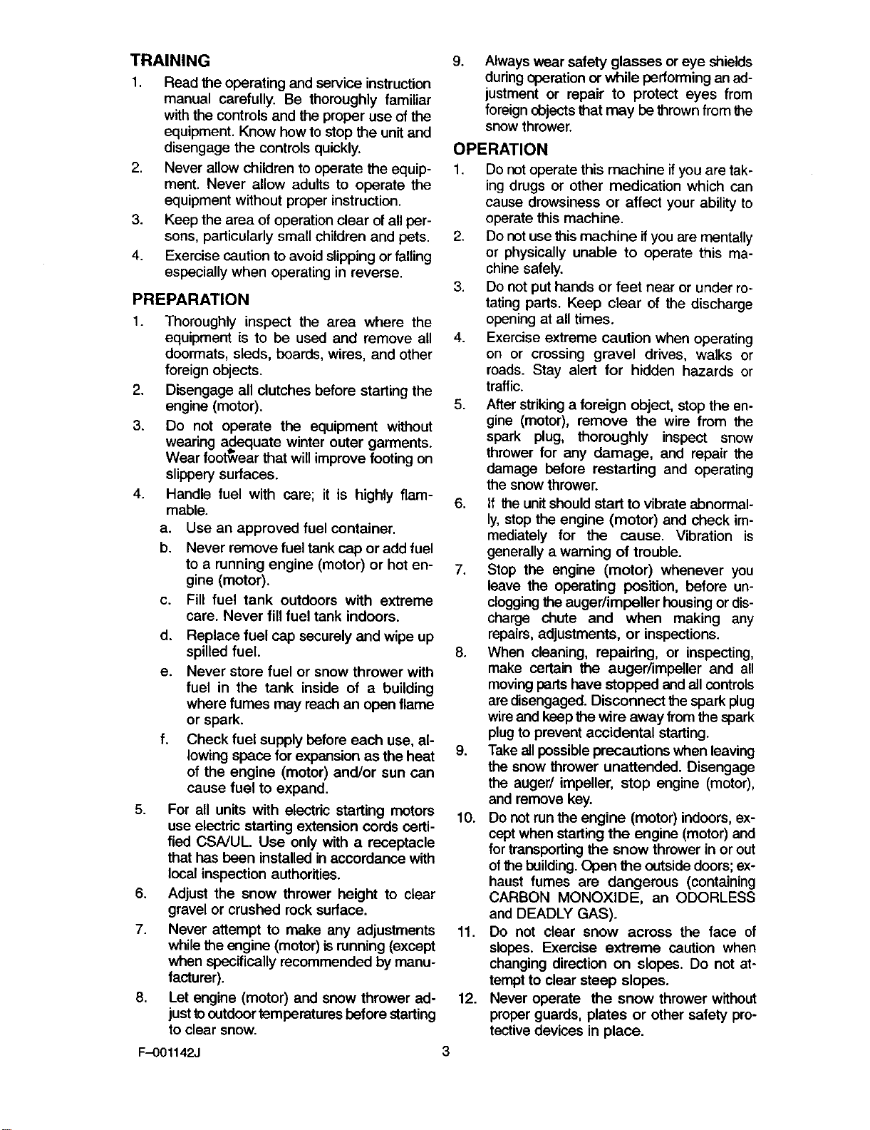
TRAINING
1. Read the operating and service instruction
manual carefully. Be thoroughly familiar
with the controls and the proper use of the
equipment. Know how to stop the unitand
disengage the controls quickly.
2. Never allow children to operate the equip-
ment. Never allow adults to operate the
equipment without proper instruction.
3. Keep the area of operation clear of all per-
sons, particularly small children and pets.
4. Exercise caution to avoid slipping or falling
especially when operating in reverse.
PREPARATION
1. Thoroughly inspect the area where the
equipment is to be used and remove all
doormats, sleds, boards, wires, and other
foreign objects.
2. Disengage all clutches before starting the
engine (motor).
3. Do not operate the equipment without
wearing adequate winter outer garments.
Ib , . ,
Wear footwear that will Mmprovefooting on
slippery surfaces.
4. Handle fuel with care; it is highly flam-
mable.
a. Use an approved fuel container.
b. Never remove fuel tank cap or add fuel
to a running engine (motor) or hot en-
gine (motor).
c. Fill fuel tank outdoors with extreme
care. Never fill fuel tank indoors.
5.
6.
7.
.
d. Replace fuel cap securely and wipe up
spilled fuel.
e. Never store fuel or snow thrower with
fuel in the tank inside of a building
where fumes may reach an open flame
or spark.
f. Check fuel supply before each use, al-
lowing space for expansion as the heat
of the engine (motor) and/or sun can
cause fuel to expand.
For all units with electric starting motors
use electric starting extension cords certi-
fied CSNUL. Use only with a receptacle
that has been installed in accordance with
local inspection authorities.
Adjust the snow thrower height to clear
gravel or crushed rock surface.
Never attempt to make any adjustments
while the engine (motor) is running (except
when specifically recommended by manu-
facturer).
Let engine (motor) and snow thrower ad-
just tooutdoor temperatures before starting
to clear snow.
F-001142J
g. Always wear safety glasses or eye shields
during operation or while performing an ad-
justment or repair to protect eyes from
foreign objects that may be thrown from the
snow thrower.
OPERATION
1. Do not operate this machine if you are tak-
ing drugs or other medication which can
cause drowsiness or affect your ability to
operate this machine.
2. Do not use this machine ifyou are mentally
or physically unable to operate this ma-
chine safely.
3. Do not put hands or feet near or under ro-
tating parts. Keep clear of the discharge
opening at all times.
4. Exercise extreme caution when operating
on or crossing gravel drives, walks or
roads. Stay alert for hidden hazards or
traffic.
5. After striking a foreign object, stop the en-
gine (motor), remove the wire from the
spark plug, thoroughly inspect snow
thrower for any damage, and repair the
damage before restarting and operating
the snow thrower.
6. If the unit should start to vibrate abnormal-
ly, stop the engine (motor) and check im-
mediately for the cause. Vibration is
generally a warning of trouble.
7. Stop the engine (motor) whenever you
leave the operating position, before un-
cloggingthe auger/impeller housing or dis-
charge chute and when making any
repairs, adjustments, or inspections.
8. When cleaning, repairing, or inspecting,
make certain the auger/impeller and all
moving parts have stopped and all controls
are disengaged. Disconnect the spark plug
wire and keep the wire away fromthe spark
plug to prevent accidental starting.
9. Take all possible precautions when leaving
the snow thrower unattended. Disengage
the auger/impeller, stop engine (motor),
and remove key.
10. Do not runthe engine (motor) indoors, ex-
ceptwhen starting the engine (motor) and
for transporting the snow thrower in or out
ofthe building.Open the outside doors;ex-
haust fumes are dangerous (containing
CARBON MONOXIDE, an ODORLESS
and DEADLY GAS).
11. Do not clear snow across the face of
slopes. Exercise extreme caution when
changing direction on slopes. Do not at-
tempt to clear steep slopes.
12. Never operate the snow thrower without
proper guards, plates or other safety pro-
tective devices in place.
3
13. Never operate the snow thrower near en-
closures, automobiles, window wells,
drop-offs, and the like without proper ad-
justment of the snow discharge angle.
Keep children and pets away.
14. Do not overload the machine capacity by
attempting to clear snow at too fast a rate.
15. Never operate the machine at high trans-
port speeds on slippery surfaces. Look be-
hind and use care when backing up.
16. Never direct discharge at bystanders or
allow anyone in front of the unit.
17. Disengage power to the collector/impelLer
when snow thrower is transported or not in
use.
18. Use only attachments and accessories ap-
proved by the manufacturer of the snow
thrower (such as tire chains, electric start
kits, ect.).
19. Never operate the snow thrower without
good visibility or light. Always be sure of
your footing and keep a firm hold on the
handlesP Walk;never run.
20. Do not over-reach. Keep proper footing
and balance at all times.
21. Do not attempt to use snow thrower on a
reef.
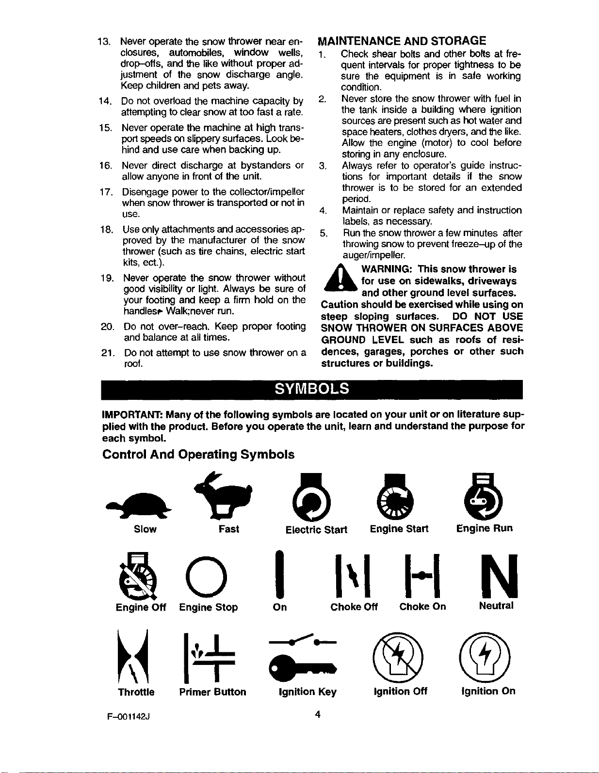
MAINTENANCE AND STORAGE
1. Check shear bolts and other belts at fre-
quent intervals for proper tightness to be
sure the equipment is in safe working
condition.
2. Never store the snow thrower with fuel in
the tank inside a building where ignition
sources are present such as hot water and
space heaters, clothesdryers, and the like.
Allow the engine (motor) to cool before
storingin any enclosure.
3. Always refer to operator's guide instruc-
tions for important details if the snow
thrower is to be stored for an extended
period.
4. Maintain or replace safety and instruction
labels, as necessary.
5. Run the snow thrower a few minutes after
throwingsnow to prevent freeze-up ofthe
auger/impeller.
,_ WARNING: This snow thrower isfor use on sidewalks, driveways
and other ground level surfaces.
Caution should be exercised while using on
steep sloping surfaces. DO NOT USE
SNOW THROWER ON SURFACES ABOVE
GROUND LEVEL such as roofs of resi-
dences, garages, porches or other such
structures or buildings.
IMPORTANT: Many of the following symbols are located on your unit or on literature sup-
plied with the product. Before you operate the unit, learn and understand the purpose for
each symbol.
Control And Operating Symbols
Slow Fast Electric Start Engine Start Engine Run
I H N
Engine Off Engine Stop On Choke Off Choke On Neutral
Throttle Primer Button Ignition Key Ignition Off G
Ignition On
F-001142J 4
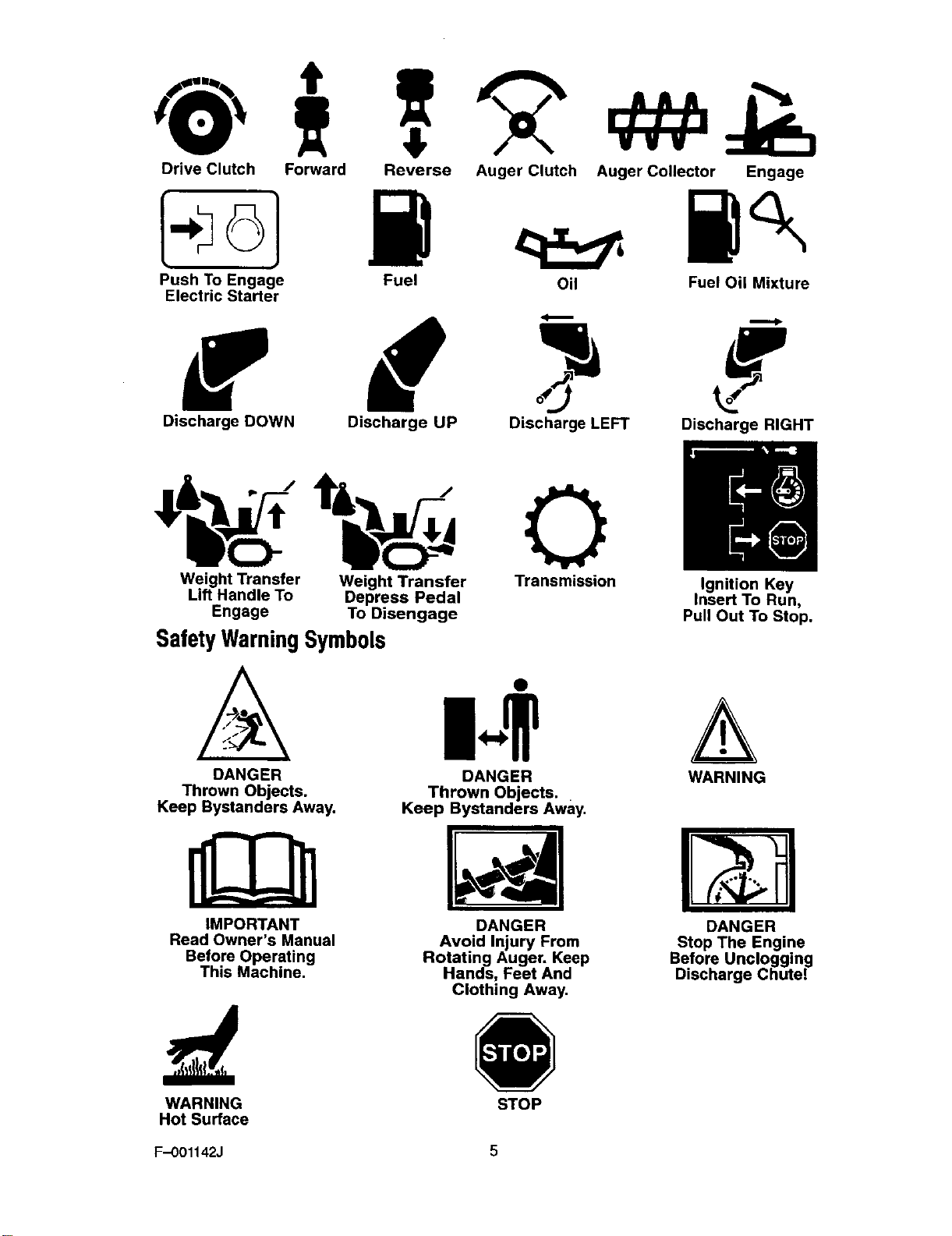
Drive Clutch Forward Reverse
k61 W
Push To Engage Fuel
Electric Starter
Auger Clutch Auger Collector Engage
Oil Fuel Oil Mixture
f d
Discharge DOWN Discharge UP Discharge LEFT Discharge RIGHT
MIni
)lm
Weight Transfer Weight Transfer Transmission Ignition Key
Lift Handle To Depress Pedal Insert To Run,
Engage To Disengage Pull Out To Stop.
SafetyWarningSymbols
A m..+
DANGER DANGER WARNING
Thrown Objects. Thrown Objects.
Keep Bystanders Away. Keep Bystanders Away.
IMPORTANT
Read Owner's Manual
Before Operating
This Machine.
DANGER
Avoid Injury From
Rotating Auger. Keep
Hands, Feet And
Clothing Away.
DANGER
Stop The Engine
Before Uncloggin_
Discharge Chute.
WARNING STOP
Hot Surface
F.-O01142J 5
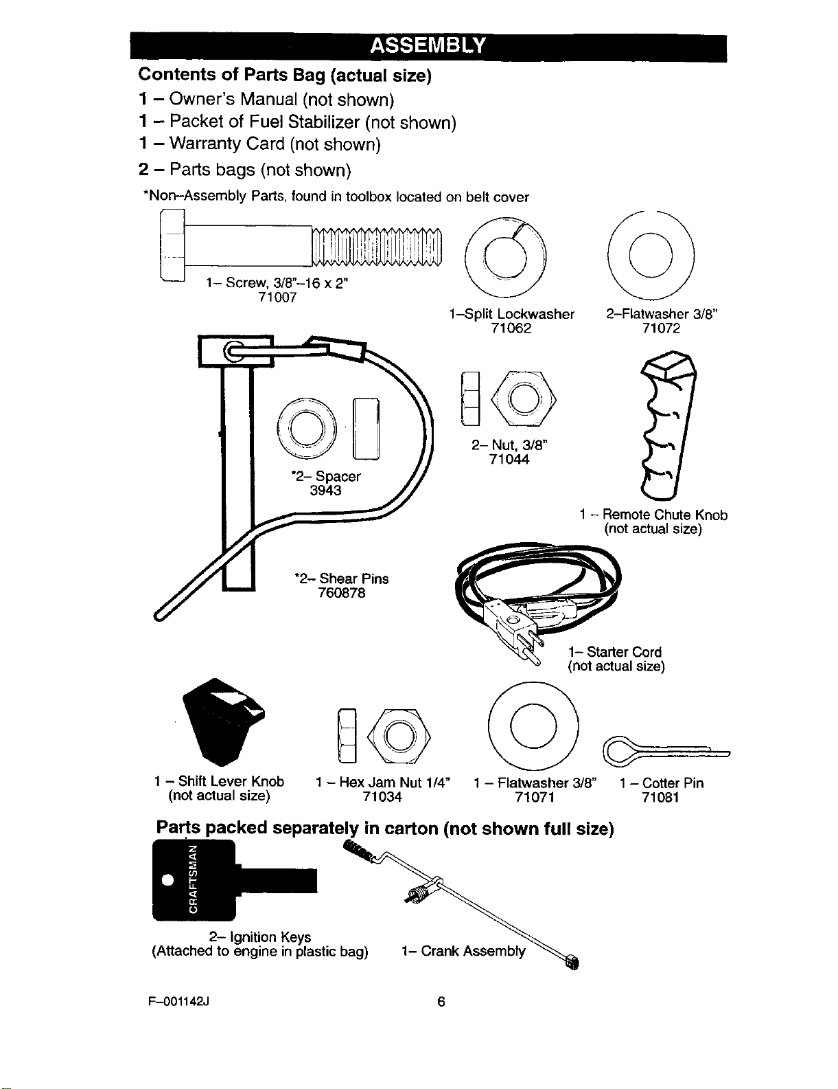
Contents of Parts Bag (actual size)
1 - Owner's Manual (not shown)
1 - Packet of Fuel Stabilizer (not shown)
1 - Warranty Card (not shown)
2-Parts bags (not shown)
*Non-Assembly Parts, found in toolbox located on belt cover
1- Screw, 3/8"-16 x 2"
71007
_ 23SP,_cer_
_.] "2- S;_Pins
1-Split Lockwasher
71062 2-Flatwasher 3/8"
71072
1 - Shift Lever Knob
(not actual size) 1 - Hex Jam Nut 1/4"
71034
1-Remote Chute Knob
(not actual size)
e ,Os°re' /
1 - Flatwasher 3/8"
71071
r
1-Cotter Pin
71081
Parts packed separately in carton (not shown full size)
2- Ignition Keys
(Attached to engine in plastic bag) 1_ ran.Assemo,y
F-OO1142J 6
Read and follow the assembly and ad-
justment instructions for your snow
thrower. All fasteners are in the parts
bag. Do not discard any parts or materi-
al until the unit is assembled.
,_ WARNING: Before doing any
assembly or maintenance to
the snow thrower, remove the
wire from the spark plug.
,_ WARNING: Always wear
safety glasses or eye
shields while assembling
snow thrower.
NOTE: In this instruction book, left
and right describe the location of a
part from the operator's position be-
hind the unit.
Tools Required
1 Knife
1 Pliers
1 1/2 inch open end wrenches
1 9/16 inch open end wrenches
1 3/4 inch open end wrenches
1 Measuring tape or ruler
1 Screwdriver
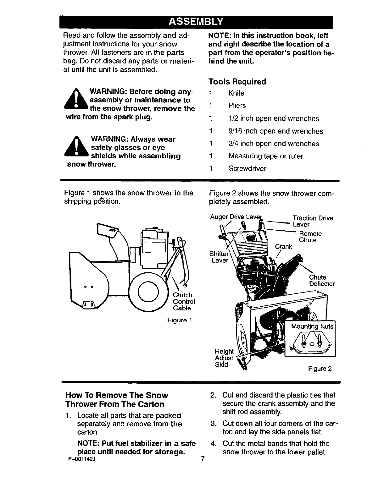
Figure 1 shows the snow thrower in the
shipping position.
_./i-_ J _ v /Control
_ Cable
Figure 1
Figure 2 shows the snow thrower com-
pletely assembled.
Auger Traction Drive
"----'--" Lever
Remote
Chute
Crank
Lever
Chute
Deflector
Height
Adjust
Skid Figure 2
How To Remove The Snow
Thrower From The Carton
1. Locate all parts that are packed
separately and remove from the
carton.
NOTE: Put fuel stabilizer in a safe
place until needed for storage.
F-O01142J
2. Cut and discard the plastic ties that
secure the crank assembly and the
shift rod assembly.
3. Cut down all four corners of the car-
ton and lay the side panels flat.
4. Cut the metal bands that hold the
snow thrower to the lower pallet.
.
.
Remove and discard all packing
material from around the snow
thrower.
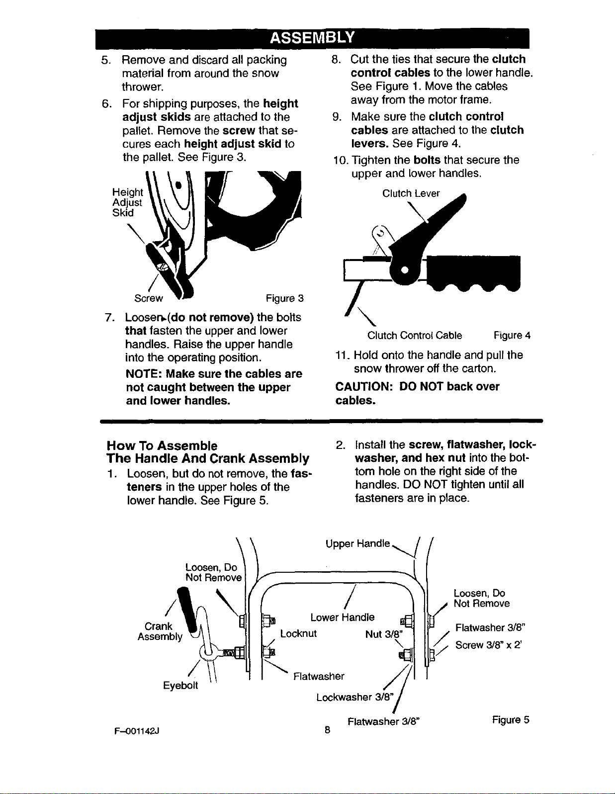
For shipping purposes, the height
adjust skids are attached to the
pallet. Remove the screw that se-
cures each height adjust skid to
the pallet. See Figure 3.
Adjust
Skid
8. Cut the ties that secure the clutch
control cables to the lower handle.
See Figure 1. Move the cables
away from the motor frame.
9. Make sure the clutch control
cables are attached to the clutch
levers. See Figure 4.
10. Tighten the bolts that secure the
upper and lower handles.
Clutch Lever
.
Screw Figure 3
Loosen,(do not remove) the bolts
that fasten the upper and lower
handles. Raise the upper handle
into the operating position.
NOTE: Make sure the cables are
not caught between the upper
and lower handles.
Clutch Control Cable Figure 4
11. Hold onto the handle and pull the
snow thrower off the carton.
CAUTION: DO NOT back over
cables.
How To Assemble
The Handle And Crank Assembly
1. Loosen, but do not remove, the fas-
teners in the upper holes of the
lower handle. See Figure 5.
.Install the screw, flatwasher, lock-
washer, and hex nut into the bot-
tom hole on the right side of the
handles. DO NOT tighten until all
fasteners are in place.
Crank
Assembly
Eyeboff
Loosen, Do_
Not Remove I
Upper Handle
LowerHandle ll_
Locknut Nut 3/8"
Flatwasher
Lockwasher 3/8"
/
Loosen, Do
i/# Not Remove
Flatwasher 3/8"
Screw 3/8" x 2'
Flatwasher 3/8" Figure 5
F-001142J 8
3. Locate the crank assembly re-
moved earlier. Remove the Iocknut
and flatwasher from the eye bolt
assembly.
4. Install the eye bolt through the low-
er hole on the left side of the han-
dles.
5. Install the flatwasher and the lock-
nut loosely on the eye bolt.
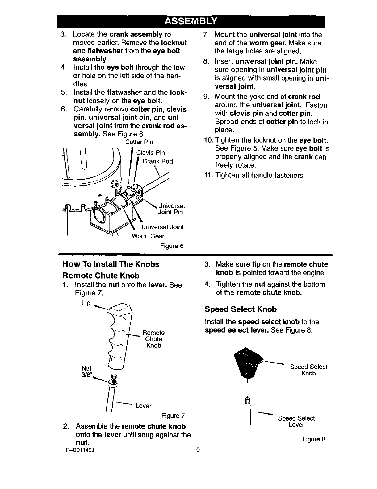
6. Carefully remove cotter pin, clevis
pin, universal joint pin, and uni-
versal joint from the crank rod as-
sembly. See Figure 6.
Cotter Pin
Clevis Pin
Crank Rod
.Mount the universal joint into the
end of the worm gear. Make sure
the large holes are aligned.
8. Insert universal joint pin. Make
sure opening in universal joint pin
is aligned with small opening in uni-
versal joint.
9. Mount the yoke end of crank rod
around the universal joint. Fasten
with clevis pin and cotter pin.
Spread ends of cotter pin to lock in
place.
10. Tighten the Iocknut on the eye bolt.
See Figure 5. Make sure eye bolt is
properly aligned and the crank can
freely rotate.
11. Tighten all handle fasteners.
tb
Universal
Joint Pin
Universal Joint
Worm Gear
Figure 6
How To Install The Knobs
Remote Chute Knob
1. Install the nut onto the lever. See
Figure 7.
Lip
_-- ,
Remote
Chute
Knob
Nut
3/8"_.._
Lever
Figure 7
2. Assemble the remote chute knob
onto the lever until snug against the
nut.
F--001142J 9
3. Make sure lip on the remote chute
knob is pointed toward the engine.
4. Tighten the nut against the bottom
of the remote chute knob.
Speed Select Knob
Install the speed select knob to the
speed select lever. See Figure 8.
Speed Select
Knob
Speed Select
Lever
Figure 8
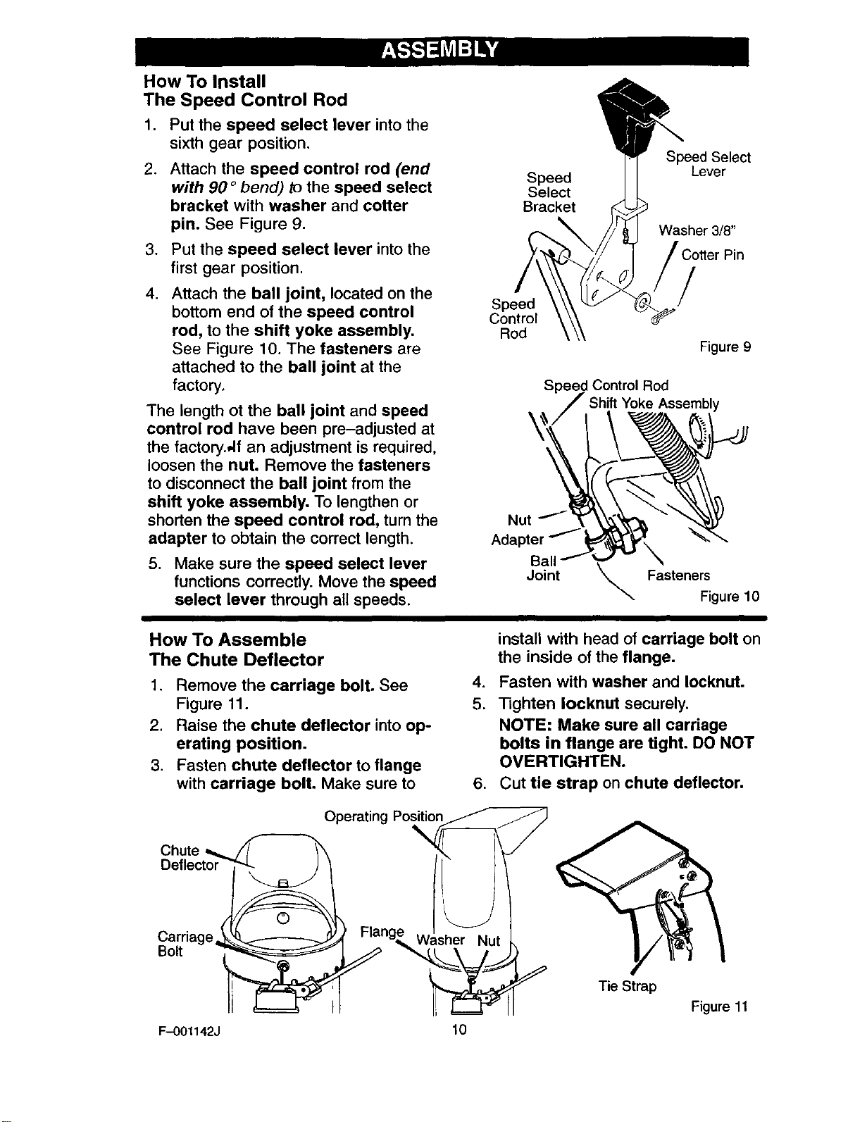
How To Install
The Speed Control Rod
1. Put the speed select lever into the
sixth gear position.
.Attach the speed control rod (end
with 90 ° bend) to the speed select
bracket with washer and cotter
pin. See Figure 9.
3. Put the speed select lever into the
first gear position.
.Attach the ball joint, located on the
bottom end of the speed control
rod, to the shift yoke assembly.
See Figure 10. The fasteners are
attached to the ball joint at the
factory.
The length ot the ball joint and speed
control rod have been pre-adjusted at
the factory.,,If an adjustment is required,
loosen the nut. Remove the fasteners
to disconnect the ball joint from the
shift yoke assembly. To lengthen or
shorten the speed control rod, turn the
adapter to obtain the correct length.
5. Make sure the speed select lever
functions correctly. Move the speed
select lever through all speeds.
_Speed Select
Speed ] [ Lever
Select
Bracket
Washer 3/8"
Speed
Control
Rod
/
Figure 9
Speed Control Rod
Assembly
Nut
Adapter
Ball
Joint _ Fasteners
Figure 10
How To Assemble
The Chute Deflector
1. Remove the carriage bolt. See
Figure 11.
2. Raise the chute deflector into op-
erating position.
3. Fasten chute deflector to flange
with carriage bolt. Make sure to
.
5.
install with head of carriage bolt on
the inside of the flange.
Fasten with washer and Iocknut.
Tighten Iocknut securely.
NOTE: Make sure all carriage
bolts in flange are tight. DO NOT
OVERTIGHTEN.
6. Cut tie strap on chute deflector.
Chute
Bolt
F-O01142J
Operatin
Flang_,_ Washer Nut
lO
Tie Strap
Figure 11

Check The Cables
1. Check the traction drive cable and
the auger drive cable. If the bottom
of the cables have become discon-
nected, reinstall the cable springs.
Make sure the long spring is at-
tached to the traction drive and the
short spring is attached to the au-
ger drive. See Figure 12.
Auger Drive Cable
Traction _.+
Drive Cable Short
/Spr+o0
I .............
.If the top of the cables have be-
come disconnected from the drive
levers, attach the cables to the "Z"
fitting. See Figure 13.
"Z" Fitting Drive Lever
\Cable Figure 13
How To Set The Skid Height
The snow thrower is equipped with
height adjustable skids mounted on
the outside of the auger housing. See
Figure 14. To adjust the height of the
skids, see "How To Adjust The Height
Of The Skids" in the Maintenance
section.
Skids Figure 14
How To Set
The Length Of The Cables
The cables were adjusted at the factory
and no adjustments should be neces-
sary. However, after the handles are put
in the operating position, the cables can
be too tight or too loose. If an adjust-
ment is necessary, see "How To Check
And Adjust The Cables" in the Service
And Adjustment section.
F-0O1142J 11
_," CHECKLIST
Before you operate your new snow
thrower, to ensure that you receive the
best performance and satisfaction from
this quality product, please review the
following checklist:
_" All assembly instructions have been
completed.
P_ The discharge chute rotates freely.
1! No remaining loose parts in carton.
While learning how to use your snow
thrower, pay extra attention to the fol-
lowing important items:
P" Engine oil is at proper level.
_" Make sure gas tank is filled properly
wnthclean, fresh, unleaded gasoline•
P" Become familiar with all controls-
their location and function. Operate
controls before starting engine.
F-OO1142J 12
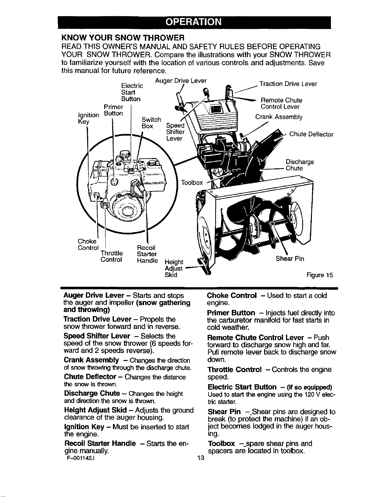
KNOW YOUR SNOW THROWER
READ THIS OWNER'S MANUAL AND SAFETY RULES BEFORE OPERATING
YOUR SNOW THROWER. Compare the illustrations with your SNOW THROWER
to familiarize yourself with the location of various controls and adjustments. Save
this manual for future reference,
Auger Drive Lever
Electric
Start
Button
Primer
Ignition Button
Key Switch
Box
Traction Drive Lever
Remote Chute
Control Lever
Crank Assembly
Chute Deflector
Discharge
Chute
Choke
Control Recoil
Throttle Starter
Control Handle Height
Adjust
Skid
Shear Pin
Figure 15
Auger Drive Lever -Starts and stops
the auger and impeller (snow gathering
and throwing)
Traction Drive Lever - Propels the
snow thrower forward and in reverse.
Speed Shifter Lever - Selects the
speed of the snow thrower (6 speeds for-
ward and 2 speeds reverse).
Crank Assembly - Changesthe direction
of snowthrowing through the dischargechute.
Chute Deflector - Changes thedistance
the snowisthrown.
Discharge Chute - Changes the height
and direction the snow is thrown.
Height Adjust Skid - Adjusts the ground
clearance of the auger housing.
Ignition Key - Must be inserted to start
the engine.
Recoil Starter Handle - Starts the en-
gine manually.
F-001142J 13
Choke Control - Used to start a cold
engine.
Primer Button - Injects fuel directlyinto
the carburetor manifold for fast startsin
cold weather.
Remote Chute Control Lever - Push
forward to discharge snow high and far.
Pull remote lever back to discharge snow
down.
Throttle Control - Controls the engine
speed.
Electric Start Button - (if so equipped)
Used to start the engine using the 120 V elec-
tric starter.
Shear Pin -Shear pins are designed to
break (to protect the machine) if an ob-
iect becomes lodged in the auger hous-
ing.
Toolbox --spare shear pins and
spacers are located in toolbox.
The operation of any snow thrower can
result in foreign objects being thrown
into the eyes, which can result in se-
vere eye damage. Always wear safety
glasses or eye shields while operating
the snow thrower.
We recommend standard safety
glasses or a wide vision safety mask for
over your glasses.
_ ARNING: Read Owner's
Manual before operating
machine. Never direct dis-
charge toward bystanders. Stop the
engine before unclogging discharge
chute or auger housing and before
leaving the machine.
TO STOP YOUR
SNOW THROWER
1. To stop t_rowing snow, release the
auger drive lever. See Figure 16.
2. To stop the wheels, release the
traction drive lever.
3. To stop the engine, push the
throttle control lever to off and pull
out the ignition key.
Traction Drive Lever
Auger Drive Lever
Figure 16
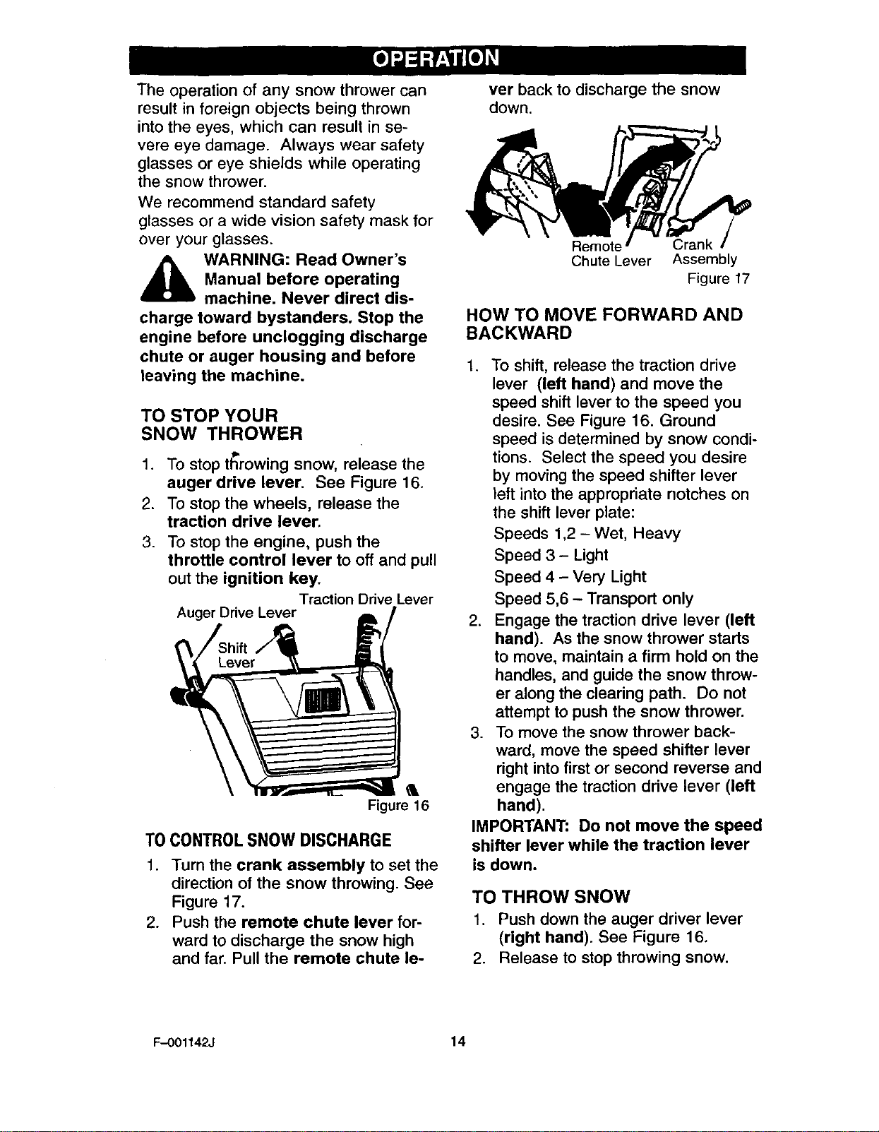
TO CONTROLSNOW DISCHARGE
1. Turn the crank assembly to set the
direction of the snow throwing. See
Figure 17.
2. Push the remote chute lever for-
ward to discharge the snow high
and far. Pull the remote chute le-
ver back to discharge the snow
down.
Chute Lever Assembly
Figure 17
HOW TO MOVE FORWARD AND
BACKWARD
1. To shift, release the traction drive
lever (left hand) and move the
speed shift lever to the speed you
desire. See Figure 16. Ground
speed is determined by snow condi-
tions. Select the speed you desire
by moving the speed shifter lever
left into the appropriate notches on
the shift lever plate:
Speeds 1,2- Wet, Heavy
Speed 3 - Light
Speed 4 - Very Light
Speed 5,6 - Transport only
2. Engage the traction drive lever (left
hand). As the snow thrower starts
to move, maintain a firm hold on the
handles, and guide the snow throw-
er along the clearing path. Do not
attempt to push the snow thrower.
3. To move the snow thrower back-
ward, move the speed shifter lever
right into first or second reverse and
engage the traction drive lever (left
hand).
IMPORTANT: Do not move the speed
shifter lever while the traction lever
is down.
TO THROW SNOW
1. Push down the auger driver lever
(right hand). See Figure 16.
2. Release to stop throwing snow.
F-001142J 14
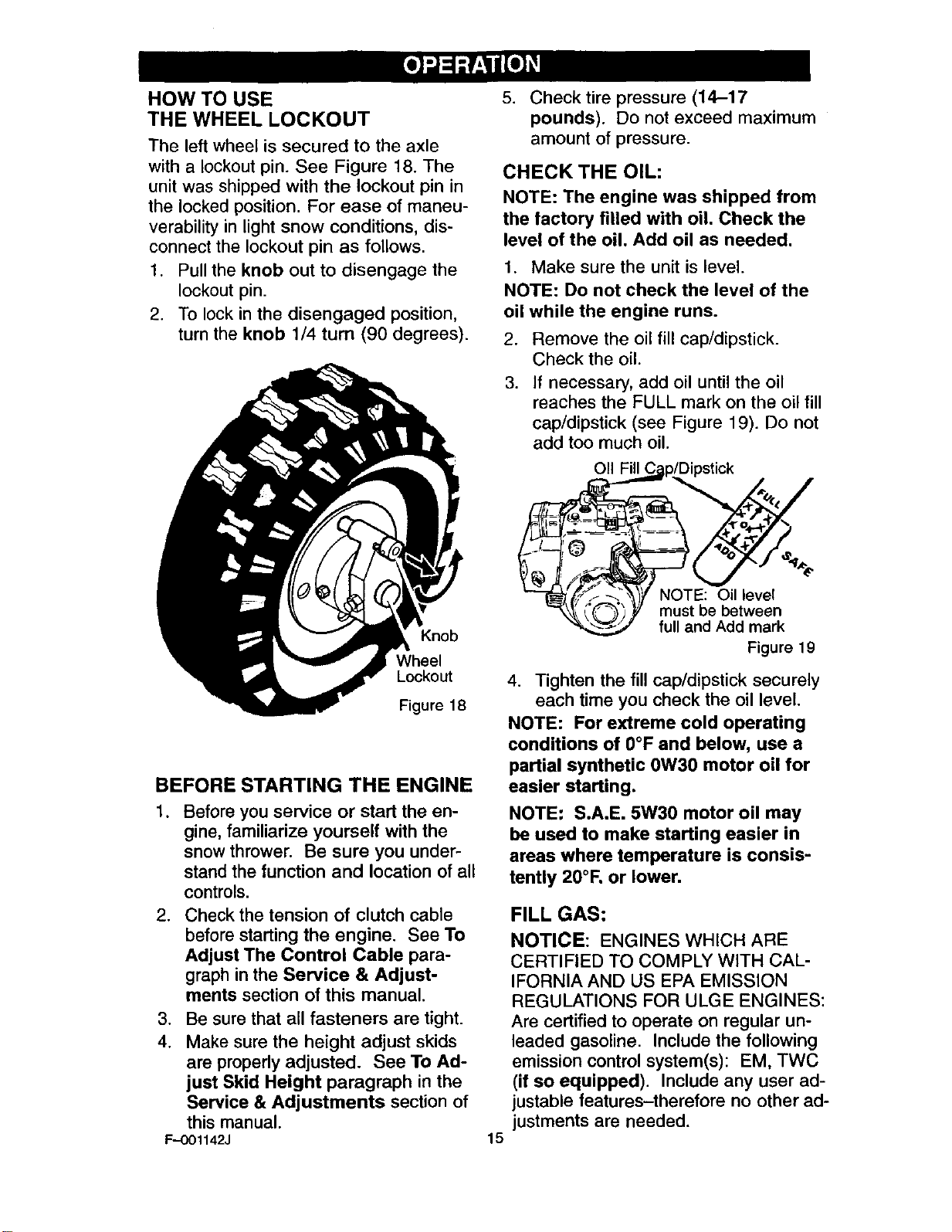
HOW TO USE
THE WHEEL LOCKOUT
The left wheel is secured to the axle
with alockout pin. See Figure 18. The
unit was shipped with the lockout pin in
the locked position. For ease of maneu-
verability in light snow conditions, dis-
connect the lockout pin as follows.
1. Pull the knob out to disengage the
lockout pin.
2. To lock in the disengaged position,
turn the knob 1/4 turn (90 degrees).
Knob
Wheel
Lockout
Figure 18
BEFORE STARTING THE ENGINE
.Before you service or start the en-
gine, familiarize yourself with the
snow thrower. Be sure you under-
stand the function and location of all
controls.
2. Check the tension of clutch cable
before starting the engine. See To
Adjust The Control Cable para-
graph in the Service & Adjust-
ments section of this manual.
,
4. Be sure that all fasteners are tight.
Make sure the height adjust skids
are properly adjusted. See To Ad-
just Skid Height paragraph in the
Service & Adjustments section of
this manual.
F--OO1142J
5. Check tire pressure (14-17
pounds). Do not exceed maximum
amount of pressure.
CHECK THE OIL:
NOTE: The engine was shipped from
the factory filled with oil. Check the
level of the oil. Add oil as needed.
1. Make sure the unit is level.
NOTE: Do not check the level of the
oil while the engine runs.
2. Remove the oil fill cap/dipstick.
Check the oil.
3. If necessary, add oil untilthe oil
reaches the FULL mark on the oil fill
cap/dipstick (see Figure 19). Do not
add too much oil.
p/Dipstick
fF_ 1_ NOTE: Oil level
/( _(_'-_J'_// must be between
"<'_'_._._._2 full and Add mark
Figure 19
4. Tighten the fill cap/dipstick securely
each time you check the oil level.
NOTE: For extreme cold operating
conditions of 0°F and below, use a
partial synthetic 0W30 motor oil for
easier starting.
NOTE: S.A.E. 5W30 motor oil may
be used to make starting easier in
areas where temperature is consis-
tently 20°1=.or lower.
15
FILL GAS:
NOTICE: ENGINES WHICH ARE
CERTIFIED TO COMPLY WITH CAL-
IFORNIA AND US EPA EMISSION
REGULATIONS FOR ULGE ENGINES:
Are certified to operate on regular un-
leaded gasoline. Include the following
emission control system(s): EM, TWC
(if so equipped). Include any user ad-
justable features-therefore no other ad-
justments are needed.
WARNING: Experiences in-
_icates that alcohol blended
fuels (called gasohol or
those using ethanol or methanol)
can attract moisture which leads to
separation and formation of acids
during storage. Acidic gas can dam-
age the fuel system of an engine
while in storage.
NOTE: To avoid engine problems,
the fuel system must be emptied be-
fore storage for 30 days or longer.
Start the engine and let it run until
the fuel lines and carburetor are
empty. Use the carburetor bowl
drain to empty residual gasoline
from the float chamber. Use fresh
fuel next season. See the Storage
section in this manual for additional
information.
Never use engine or carburetor
cleaner products in the fuel tank or
permanent damage may occur.
.Fill the fuel tank only with a fresh,
clean, unleaded regular, unleaded
premium, or reformulated automo-
tive gasoline. DO NOT use leaded
gasoline. Make sure that the con-
tainer you pour the gasoline from is
clean and free from rust or other for-
eign particles. Never use gasoline
that may be stale from long periods
of storage in the container.
,_ WARNING: Gasoline is flam-
mable. Always use caution
when handling or storing
gasoline.
Do not fill fuel tank while snow
thrower is running, when it is hot, or
when snow thrower is in an en-
closed area.
Keep away from open flame or an
electrical spark and do not smoke
while filling the fuel tank.
Never fill the tank completely. Fill
the tank to within 1/4"-112" from the
top to provide space for expansion
of fuel.
Always fill fuel tank outdoors and
use a funnel or spout to prevent
spilling.
Make sure to wipe up any spilled
fuel before stating the engine.
Store gasoline in a clean, approved
container and keep the cap in place
on the container.
TO STOP ENGINE
To stop engine, move the throttle con-
trol lever to "STOP" position and re-
move key. Keep the key in a safe
place. The engine will not start without
the key.
TO START ENGINE
(ELECTRIC STARTER, IF
EQUIPPED)
Be sure that the engine has sufficient
oil. The snow thrower engine is
equipped with a 120 volt A.C. electric
F-001142J 16
starter and recoil starter. Before start-
ing the engine, be certain that you have
read the following information.
_ll ARNING: The starter is
equipped with a three-wire
power cord and plug and is
designed to operate on 120 volt AC
household current.It must be proper-
ly grounded at all times to avoid the
possibility of electrical shock which
may be injurious to operator. Follow
all instructions carefully as set forth
in the "To Start Engine" section. De-
termine that your house wiring is a
three-wire grounded system. Ask a
licensed electrician if you are not
sure. If your house wire system is
not a three-wire system, do not use
this electric starter under any condi-
tions. If yo0r system is grounded
and a three-hole receptacle is not
available at the point your starter will
normally be used, one should be
installed by a licensed electrician.
when connecting 120 volt AC "Power
Cord", always connect the cord to
the Switch Box" on the engine first,
then plug the other end into the
three-hole grounded receptacle.
When disconnecting "Power cord",
always unplug the end in the three-
hole grounded receptacle first.
COLD START
.
3.
1. Be sure auger drive and traction
drive levers are in the disengaged
(RELEASED) position.
Move throttle control to"FAST' posi-
tion.
Remove the keys form the plastic
bag. Insert one key into ignition
slot. Make sure it snaps into place.
Do not turn key. Keep the second
key in a safe place.
4. Rotate choke knob clockwise to the
choke ON position.
5. Connect the power cord to the
switch box on the engine.
6. Plug other end of power cord into a
three-hole, grounded 120 VOLT, AC
F-001142J 17
receptacle. (See WARNING in this
section).
7. Push the primer button while cov-
ering the vent hole as follows: Re-
move finger from primer button
between primes.
Do not prime if temperature above
50 °F (10°C).
Push two time if temperature is 50 °
F (10° C) to 15°F (-10 ° C).
Push four times if temperature is
below 15° F (-10 ° C).
8. Push down on the starter button
until the engine starts. Do not crank
for more than 10 seconds at a time.
This electric starter is thermally pro-
tected. If overheated it will stop au-
tomatically and can be restarted
only when it has cooled to a safe
temperature (a wait of about 5 to 10
minutes is required).
9. When the engine starts, release the
starter button and move choke le-
ver to "1/2 choke" position. When
engine runs smoothly, move choke
lever to "No Choke" Position.
10. Disconnect power cord from recep-
tacle, first, and then from switch
box.
NOTE: Allow the engine to warm
up for several minutes before
blowing snow in temperatures
below 0°F.
11. Run engine at full throttle "FAST'
when throwing snow.
WARM START
If restarting a warm engine after a short
shutdown, leave choke at "OFF" and do
not push the primer button. If the en-
gine fails to start, follow the Cold Start
instructions.
TO START ENGINE
(RECOIL STARTER)
Be sure that the engine has sufficient
oil. The snow thrower engine is
equipped with arecoil starter. Before
starting the engine, be certain that you
have read the following information.
COLD START
.
.
3.
Be sure auger drive and traction
drive levers are in the disengaged
(RELEASED) position.
Move throttle control to"FAST" posi-
tion.
Remove the keys form the plastic
bag. Insert one key into ignition
slot. Make sure it snaps into place.
Do not turn key. Keep the second
key in a safe place.
4. Rotate choke knob clockwise to the
choke ON position.
5. Push the primer button while cov-
ering the vent hole as follows: Re-
move finger from primer button
between primes.
Do not prime if temperature above
50°F (10 ° C).
Push two time if temperature is 50°
F (10 °C) to 15°F (-10 ° C).
Push four times if temperature is
below 15° F (-10 ° C).
6. Pull the starter handle rapidly. Do
not allow the handle to snap back,
but allow it to rewind slowly while
keeping a firm hold on the starter
handle.
.
.
As the engine warms up, move
choke lever to "1/2 choke" position.
When engine runs smoothly, move
choke lever to "No Choke" Posi-
tion.
NOTE: Allow the engine to warm
up for several minutes before
blowing snow in temperatures
below 0°E
Run engine at full throttle "FAST'
when throwing snow.
WARM START
If restarting a warm engine after a short
shutdown, leave choke at "OFF" and do
not push the primer button. If the en-
gine fails to start, follow the Cold Start
instructions.
FROZEN STARTER
If the starter is frozen and will not turn
engine:
1. Pull as much rope out of the starter
as possible.
2. Release the starter handle and let it
snap back against the starter.
If the engine stillfails to start, repeat the
two previous steps untilthe engine
starts. Then continue with the direc-
tions for cold start.
To help prevent possible freeze-up of
recoil starter and engine controls, pro-
ceed as follows after each snow remov-
al job.
1. With the engine running, pull the
starter rope hard with a continuous
full arm stroke three or four times.
Pulling of starter rope will produce a
loud clattering sound. This is not
harmful to the engine or starter.
2. With the engine not running, wipe all
snow and moisture from the carbu-
retor cover in area of control levers.
Also move throttle control, choke
control, and starter handle several
times.
,_ WARNING: Never run en-
gine indoors or in enclosed,
poorly ventilated areas. En-
gine exhaust contains CARBON
MONOXIDE, AN ODORLESS AND
DEADLY GAS. Keep hands, feet,
hair and loose clothing away from
any moving parts on engine and
snow thrower.
The temperature of muffler and
nearby areas may exceed 150°F.
Avoid these areas.
DO NOT allow children or young
teenagers to operate or be near
snow thrower while it is operating.
F-001142J 18
,_ WARNING: Do not attempt
to remove any item that may
become lodged in auger
without taking the following precau-
tions:
•Release auger drive lever.
•Move throttle lever to stop posi-
tion.
•Remove (do not turn) ignition
key.
•Disconnect spark plug wire.
•Do not place your hands in the
auger or discharge chute. Use a
pry bar.
SNOW THROWING TIPS
1. For maximum snow thrower efficien-
ii.
cy in removing snow, adjust ground
speed, NEVER the throttle. Go
slower in deep, freezing or wet
snow. If the wheels slips, reduce
forward speed. The engine is de-
signed to deliver maximum perfor-
mance at full throttle and should be
run at this power setting at all times.
2. Most efficient snow throwing is ac-
complished when the snow is re-
moved immediately after if falls.
3. For complete snow removal, slightly
overlap each path previously taken.
4. The snow should be discharged
down wind whenever possible.
5. For normal usage, set the skids so
that the scraper bar is 1/8" above
the skids. For extremely hard-
packed snow surfaces, adjust the
.
.
.
9.
skids upward so that the scraper
bar touches the ground.
On gravel or crushed rock surfaces,
set the skids at 1-1/4" below the
scraper bar. See To Adjust Skid
Height paragraph in the Service &
Adjustments section of this manu-
al. Rocks and gravel must not be
picked up and thrown by the ma-
chine.
After the snow throwing job has
been completed, allow the engine to
idle for a few minutes, which will
melt snow and accumulated ice off
the engine.
Clean the snow thrower thoroughly
after each use.
Remove ice and snow accumulation
and all debris from the entire snow
thrower, and flush with water (if pos-
sible) to remove all salt or other
chemicals. Wipe snow thrower dry.
F-OO1142J 19
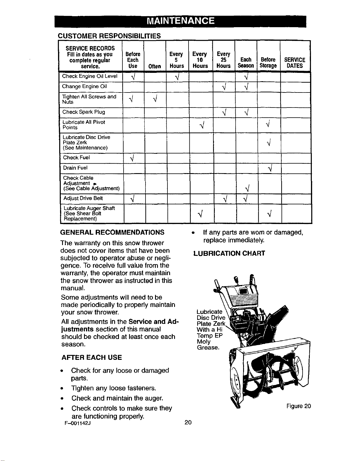
CUSTOMER RESPONSIBILITIES
SERVICE RECORDS
Fill in dates as you Before
completeregular Each
service. Use
Check Engine Oil Level _j
Change Engine Oil
_ghten All Screws and
Nuts
Check Spark Plug
Lubricate All Pivot
Points
Often
Every Every Every
5 10 25 Each Before SERVICE
Hours Hours Hours Season Storage DATES
.j
q
Lubricate Disc Drive
Plate Zerk
(See Maintenance)
Check Fuel
Drain Fuel
Check Cable
Adjustment _.
(See Cable Adjustment)
Adjust Drive Belt
Lubricate Auger Shaft
(See Shear Bolt
Replacement)
GENERAL RECOMMENDATIONS
The warranty on this snow thrower
does not cover items that have been
subjected to operator abuse or negli-
gence. To receive full value from the
warranty, the operator must maintain
the snow thrower as instructed in this
manual.
Some adjustments will need to be
made periodically to properly maintain
your snow thrower.
All adjustments in the Service and Ad-
justments section of this manual
should be checked at least once each
season.
AFTER EACH USE
• Check for any loose or damaged
parts.
• Tighten any loose fasteners.
•Check and maintain the auger.
• Check controls to make sure they
are functioning properly.
F-001142J
•If any parts are worn or damaged,
replace immediately.
LUBRICATION CHART
Lubric,, ' J
Disc Drive _=1__
Plate Zerk. _11_'_
With a Hi ii_
Temp EP _/
Moly -----_ml _
Grease.
Figure20
2O
PRODUCT SPECIFICATIONS
HORSEPOWER 11.0 HP
DISPLACEMENT 21.82 cu. in.
GASOLINE 4 quarts
CAPACITY (unleaded)
OIL CAPACITY 5W30
20 oz capacity)
SPARK PLUG: Champion RJ19LM
(Gap .030 in.) or
equivalent
VALVE CLEARANCE: Intake: .010 In.
Exhaust: .010 In.
SNOW T_ROWER
AS REQUIRED
The following adjustment should be
preformed more than once each sea-
son.
1. Auger drive belt should be adjusted
after the first 2 to 4 hours of use,
again about mid-season and twice
each season thereafter (See to Ad-
just Belts paragraph in the Ser-
vice and Adjustment section).
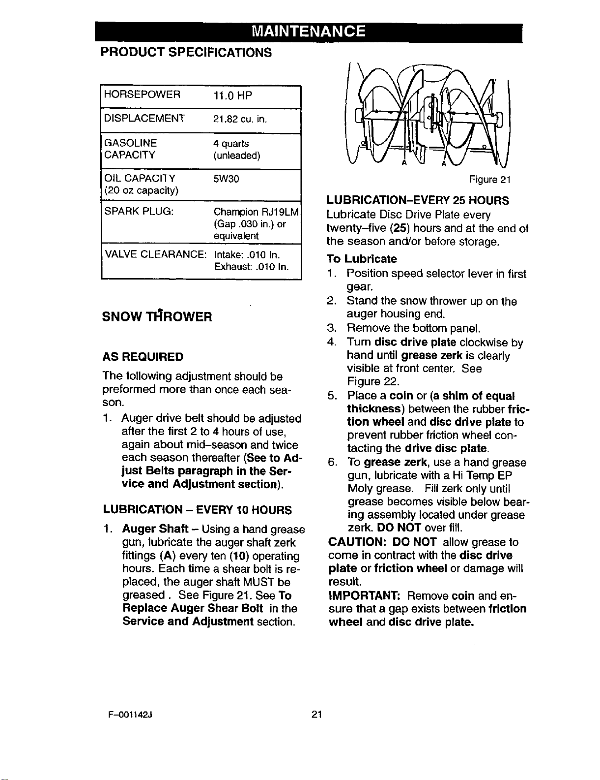
LUBRICATION - EVERY 10 HOURS
.Auger Shaft - Using a hand grease
gun, lubricate the auger shaft zerk
fittings (A) every ten (10) operating
hours. Each time ashear bolt is re-
placed, the auger shaft MUST be
greased. See Figure 21. See To
Replace Auger Shear Bolt in the
Service and Adjustment section.
Figure 21
LUBRICATION-EVERY 25 HOURS
Lubricate Disc Drive Plate every
twenty-five (25) hours and at the end of
the season and/or before storage.
To Lubricate
1. Position speed selector lever in first
gear.
2. Stand the snow thrower up on the
auger housing end.
3. Remove the bottom panel.
4. Turn disc drive plate clockwise by
hand until grease zerk is clearly
visible at front center. See
Figure 22.
5. Place a coin or (a shim of equal
thickness) between the rubber fric-
tion wheel and disc drive plate to
prevent rubber friction wheel con-
tacting the drive disc plate.
6. To grease zerk, use a hand grease
gun, lubricate with a Hi Temp EP
Moly grease. Fill zerk only until
grease becomes visible below bear-
ing assembly located under grease
zerk. DO NOT over fill.
CAUTION: DO NOT allow grease to
come in contract with the disc drive
plate or friction wheel or damage will
result.
IMPORTANT: Remove coin and en-
sure that agap exists between friction
wheel and disc drive plate.
F-001142J 21
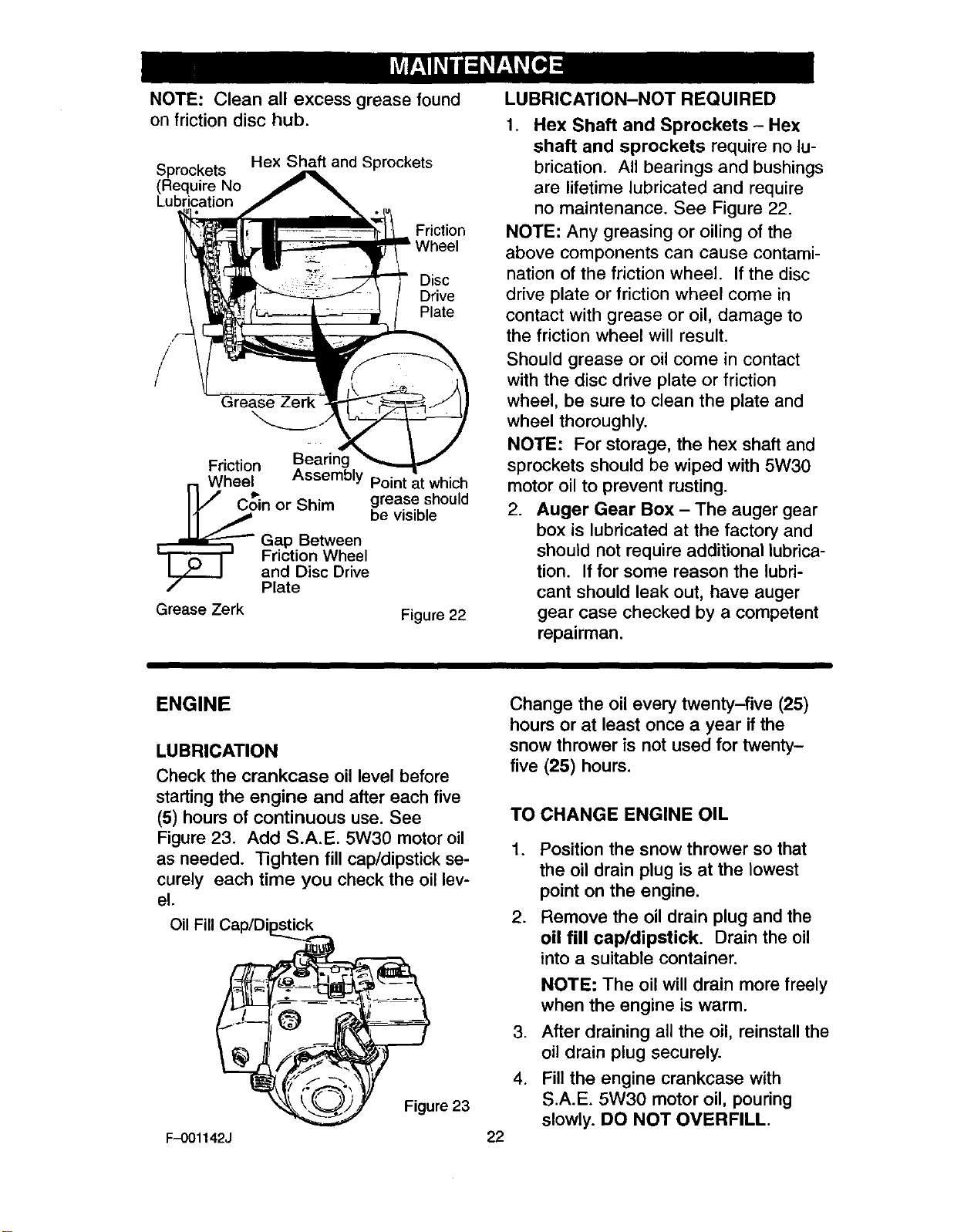
NOTE: Clean all excess grease found
on friction disc hub.
Sprockets
(Require No
Lubrication
Hex Shaft and Sprockets
Friction
Disc
Drive
Plate
Friction Bearing
Wheel Assembly Point at which
C_in or Shim grease should
be visible
Gap Between
Friction Wheel
and Disc Drive
Plate
Grease Zerk Figure 22
LUBRICATION-NOT REQUIRED
1. Hex Shaft and Sprockets -Hex
shaft and sprockets require no lu-
brication. All bearings and bushings
are lifetime lubricated and require
no maintenance. See Figure 22.
NOTE: Any greasing or oiling of the
above components can cause contami-
nation of the friction wheel. If the disc
drive plate or friction wheel come in
contact with grease or oil, damage to
the friction wheel will result.
Should grease or oil come in contact
with the disc drive plate or friction
wheel, be sure to clean the plate and
wheel thoroughly.
NOTE: For storage, the hex shaft and
sprockets should be wiped with 5W30
motor oil to prevent rusting.
2. Auger Gear Box - The auger gear
box is lubricated at the factory and
should not require additional lubrica-
tion. If for some reason the lubri-
cant should leak out, have auger
gear case checked by a competent
repairman.
ENGINE
LUBRICATION
Check the crankcase oil level before
starting the engine and after each five
(5) hours of continuous use. See
Figure 23. Add S.A.E. 5W30 motor oil
as needed. "Rghten fill cap/dipstick se-
curely each time you check the oil lev-
el.
Oil Fill Cap/Di
F-001142J
Figure 23
Change the oil every twenty-five (25)
hours or at least once a year if the
snow thrower is not used for twenty-
five (25) hours.
TO CHANGE ENGINE OIL
22
1.
.
.
4.
Position the snow thrower so that
the oil drain plug is at the lowest
point on the engine.
Remove the oil drain plug and the
oil fill cap/dipstick. Drain the oil
into a suitable container.
NOTE: The oil will drain more freely
when the engine is warm.
After draining all the oil, reinstall the
oil drain plug securely.
Fill the engine crankcase with
S.A.E. 5W30 motor oil, pouring
slowly. DO NOT OVERFILL.
,_ WARNING: Always discon-
nect the spark plug wire and
place it where it cannot
make contact with spark plug to pre-
vent accidental starting when mak-
ing any adjustments or repairs.
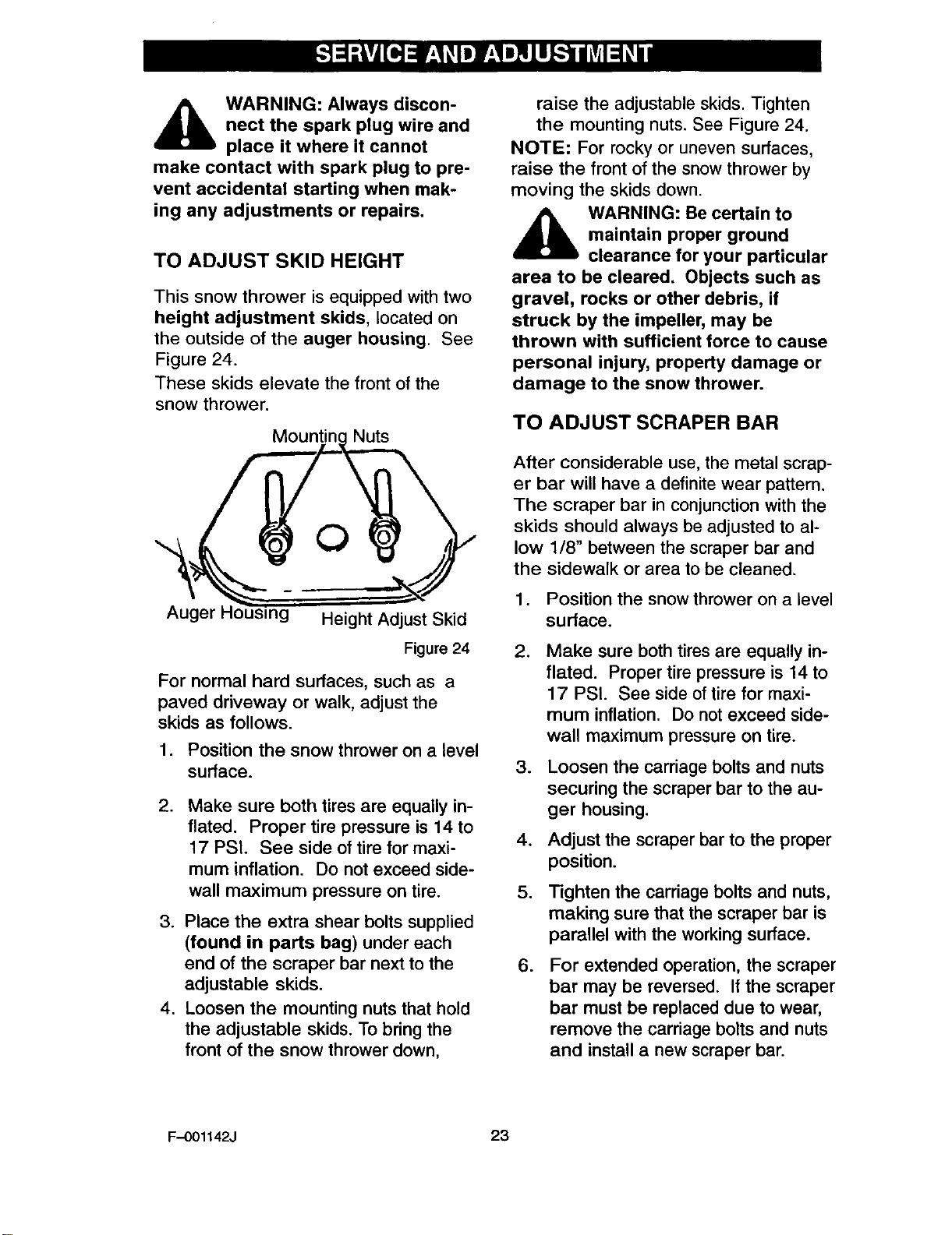
TO ADJUST SKID HEIGHT
This snow thrower is equipped with two
height adjustment skids, located on
the outside of the auger housing. See
Figure 24.
These skids elevate the front of the
snow thrower.
Mountin( Nuts
Auger g Height Adjust Skid
Figure 24
For normal hard surfaces, such as a
paved driveway or walk, adjust the
skids as follows.
1. Position the snow thrower on a level
surface.
.Make sure both tires are equally in-
flated. Proper tire pressure is 14 to
17 PSI. See side of tire for maxi-
mum inflation. Do not exceed side-
wall maximum pressure on tire.
3. Place the extra shear bolts supplied
(found in parts bag) under each
end of the scraper bar next to the
adjustable skids.
4. Loosen the mounting nuts that hold
the adjustable skids. To bring the
front of the snow thrower down,
raise the adjustable skids. Tighten
the mounting nuts. See Figure 24.
NOTE: For rocky or uneven surfaces,
raise the front of the snow thrower by
moving the skids down.
,_ WARNING: Be certain to
maintain proper ground
clearance for your particular
area to be cleared. Objects such as
gravel, rocks or other debris, if
struck by the impeller, may be
thrown with sufficient force to cause
personal injury, property damage or
damage to the snow thrower.
TO ADJUST SCRAPER BAR
After considerable use, the metal scrap-
er bar will have a definite wear pattern.
The scraper bar in conjunction with the
skids should always be adjusted to al-
low 1/8" between the scraper bar and
the sidewalk or area to be cleaned.
1. Position the snow thrower on a level
surface.
,Make sure both tires are equally in-
flated. Proper tire pressure is 14 to
17 PSI. See side of tire for maxi-
mum inflation. Do not exceed side-
wall maximum pressure on tire.
3. Loosen the carriage bolts and nuts
securing the scraper bar to the au-
ger housing.
4, Adjust the scraper bar to the proper
position.
5. _ghten the carriage bolts and nuts,
making sure that the scraper bar is
parallel with the working surface.
.For extended operation, the scraper
bar may be reversed. If the scraper
bar must be replaced due to wear,
remove the carriage bolts and nuts
and install a new scraper bar.
F-001142J 23
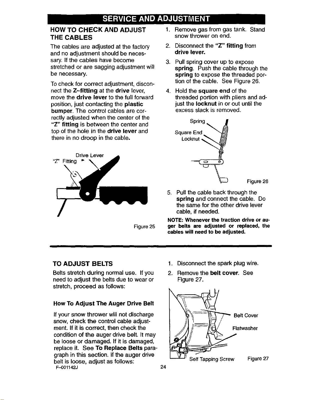
HOW TO CHECK AND ADJUST
THE CABLES
The cables are adjusted at the factory
and no adjustment should be neces-
sary. If the cables have become
stretched or are sagging adjustment will
be necessary.
To check for correct adjustment, discon-
nect the Z-fitting at the drive lever,
move the drive lever to the full forward
position, just contacting the plastic
bumper. The control cables ere cor-
rectly adjusted when the center of the
"Z" fitting is between the center and
top of the hole in the drive lever and
there in no droop in the cable.
.
2.
3.
.
Remove gas from gas tank. Stand
snow thrower on end.
Disconnect the "Z" fitting from
drive lever.
Pull spring cover up to expose
spring. Push the cable through the
spring to expose the threaded por-
tion of the cable. See Figure 26.
Hold the square end of the
threaded portion with pliers and ad-
just the Iocknut in or out until the
excess slack is removed.
Spring
Square End
Locknut,
Drive Lever
"Z" Fitting _"
Figure 25
Figure 26
,Pull the cable back through the
spring and connect the cable. Do
the same for the other drive lever
cable, if needed.
NOTE: Whenever the traction drive or au-
ger belts are adjusted or replaced, the
cables will need to be adjusted.
TO ADJUST BELTS
Belts stretch during normal use, If you
need to adjust the belts due to wear or
stretch, proceed as follows:
How To Adjust The Auger Drive Belt
If your snow thrower will not discharge
snow, check the control cable adjust-
ment. If it is correct, then check the
condition of the auger drive belt. It may
be loose or damaged. If it is damaged,
replace it. See To Replace Belts para-
graph in this section. If the auger drive
belt is loose, adjust as follows:
F-001142J 24
1. Disconnect the spark plug wire.
2. Remove the belt cover. See
Figure 27.
Self Tapping Screw Figure 27
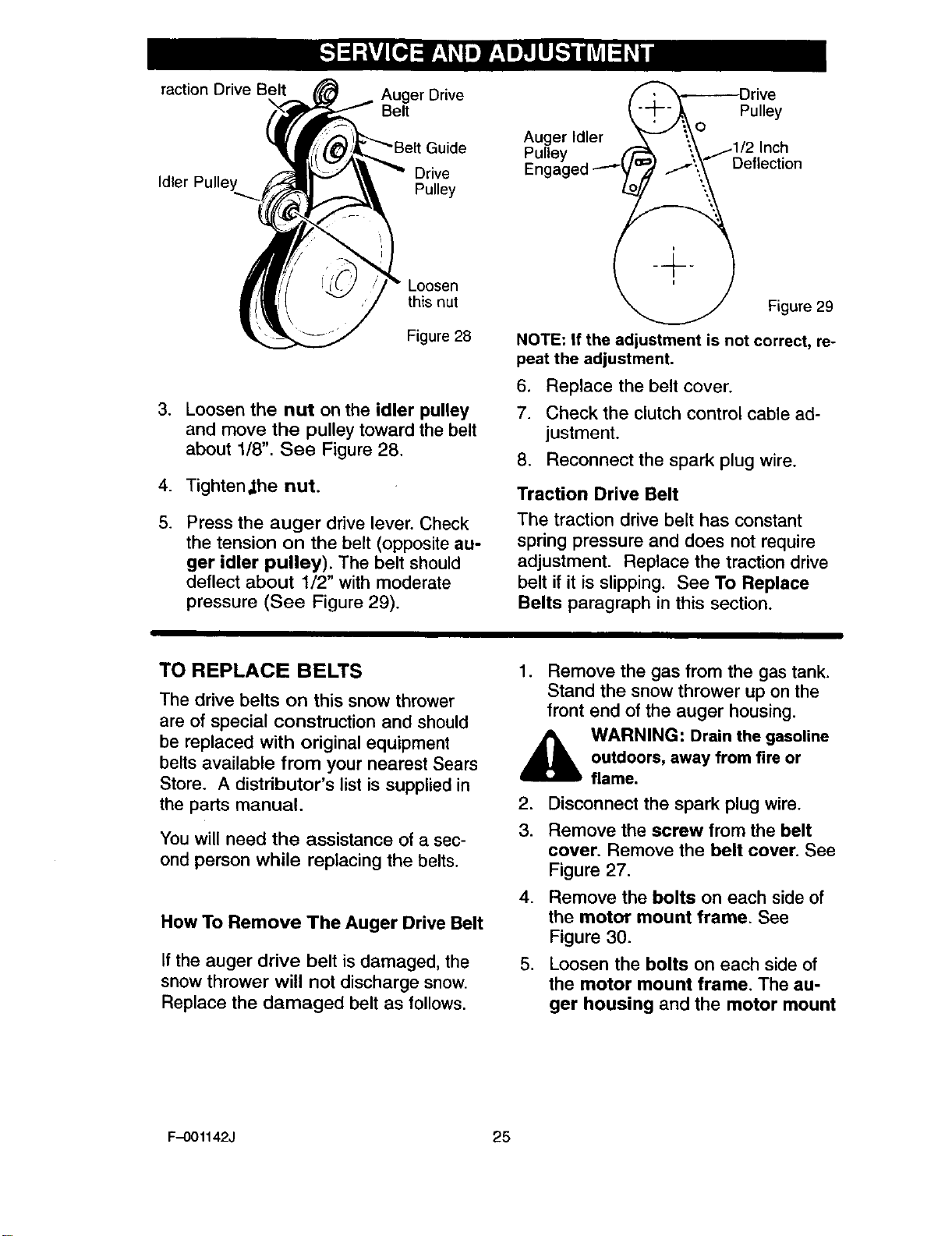
faction Drive Belt Auger Drive
Belt
Drive
Idler Pulley Pulley
Loosen
this nut
Figure 28
3. Loosen the nut on the idler pulley
and move the pulley toward the belt
about 1/8". See Figure 28.
4. Tighten,the nut.
5. Press the auger drive lever. Check
the tension on the belt (opposite au-
ger idler pulley). The belt should
deflect about 1/2" with moderate
pressure (See Figure 29).
_ .'T",_Driv e
'_.o Pulley
Auger Idler : ._ ;,_,..fl/2 inch
Pulley =7 ...f',, Deflection
Engaged---" !_1"
_Figure 29
NOTE: If the adjustment is not correct, re-
peat the adjustment.
6. Replace the belt cover.
7. Check the clutch control cable ad-
justment.
8. Reconnect the spark plug wire.
Traction Drive Belt
The traction drive beet has constant
spring pressure and does not require
adjustment. Replace the traction drive
belt if it is slipping. See To Replace
Belts paragraph in this section.
TO REPLACE BELTS
The drive belts on this snow thrower
are of special construction and should
be replaced with original equipment
belts available from your nearest Sears
Store. A distributor's list is supplied in
the parts manual.
You will need the assistance of a sec-
ond person while replacing the belts.
How To Remove The Auger Drive Belt
If the auger drive belt is damaged, the
snow thrower will not discharge snow.
Replace the damaged belt as follows.
1. Remove the gas from the gas tank.
Stand the snow thrower up on the
front end of the auger housing.
_ARNING: Drain the gasoline
outdoors, away from fire or
flame.
2, Disconnect the spark plug wire.
3. Remove the screw from the belt
cover. Remove the belt cover. See
Figure 27,
4. Remove the bolts on each side of
the motor mount frame. See
Figure 30.
5, Loosen the bolts on each side of
the motor mount frame. The au-
ger housing and the motor mount
F-001142J 25
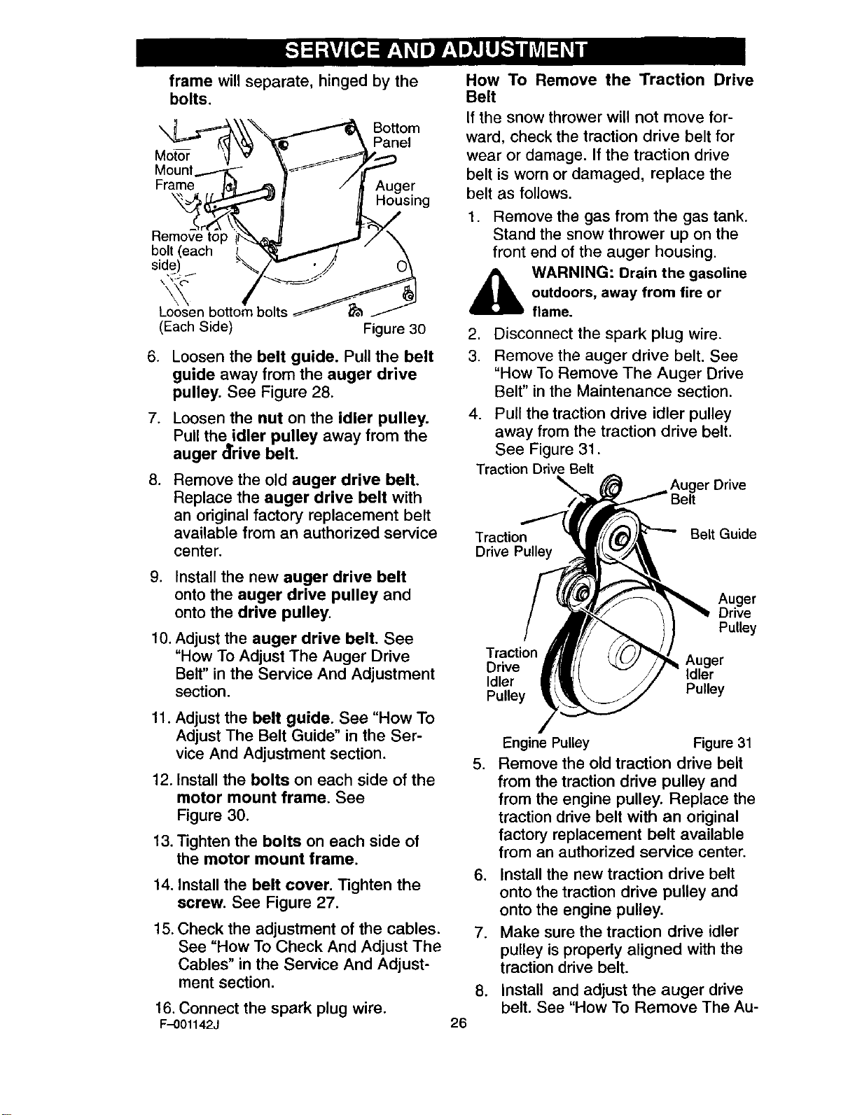
frame will separate, hinged by the
bolts.
\_ _\\'_ _ Bottom
Mount ---'_3k-_ F- /
Frame I_ _ /Auger
_._ _H°using
Remove top I_ _ J
bolt (each _L _ _ \
side) / _/" " ._j O\
; m/2s
L_sen botto
(Each Side) Figure 30
6. Loosen the belt guide. Pull the belt
guide away from the auger drive
pulley. See Figure 28.
.
.
Loosen the nut on the idler pulley.
Pull the,,idler pulley away from the
auger drive belt.
Remove the old auger drive belt.
Replace the auger drive belt with
an original factory replacement belt
available from an authorized service
center.
9. Install the new auger drive belt
onto the auger drive pulley and
onto the drive pulley.
10. Adjust the auger drive belt. See
"How To Adjust The Auger Drive
Belt" in the Service And Adjustment
section.
11. Adjust the belt guide. See "How To
Adjust The Belt Guide" in the Ser-
vice And Adjustment section.
12. Install the bolts on each side of the
motor mount frame. See
Figure 30.
13. Tighten the bolts on each side of
the motor mount frame.
14. Install the belt cover. Tighten the
screw. See Figure 27.
15. Check the adjustment of the cables.
See "How To Check And Adjust The
Cables" in the Service And Adjust-
ment section.
16. Connect the spark plug wire.
F-001142J
How To Remove the Traction Drive
Belt
If the snow thrower will not move for-
ward, check the traction drive belt for
wear or damage. If the traction drive
belt is worn or damaged, replace the
belt as follows.
1. Remove the gas from the gas tank.
Stand the snow thrower up on the
front end of the auger housing.
,_ WARNING: Drain the gasoline
outdoors, away from fire or
flame.
,
3. Disconnect the spark plug wire.
Remove the auger drive belt. See
"How To Remove The Auger Drive
Belt" in the Maintenance section.
4. Pull the traction drive idler pulley
away from the traction drive belt.
See Figure 31.
TractionDrive Belt Drive
Traction Belt Guide
Drive Pulley
Auger
Drive
Pulley
Traction
Drive Auger
Idler Idler
Pulley Pulley
,
Engine Pulley Figure 31
Remove the old traction drive belt
from the traction drive pulley and
from the engine pulley. Replace the
traction drive belt with an original
factory replacement belt available
from an authorized service center.
6. Install the new traction drive belt
onto the traction drive pulley and
onto the engine pulley.
7. Make sure the traction drive idler
pulley is properly aligned with the
traction drive belt.
.
26
Install and adjust the auger drive
belt. See "How To Remove The Au-
ger DriveBelt"in the ServiceAnd
Adjustmentsection.
9. Adjustthe belt guide. See "How To
AdjustThe BeltGuide" in the Ser-
vice And Adjustmentsection.
10.Installthe boltson each side of the
motormountframe. See Figure 30.
11.Tightenthebolts on each side of the
motormountframe.
12.Installthe belt cover.Tighten screw.
See Figure27.
13.Checktheadjustmentof thecables.
See"HowTo CheckAnd Adjust The
Cables"in the Service And Adjust-
mentsection.
14.Connectthe spark plug wire.
HOW TO ADJUST THE BELT GUIDE
1. Disconnect spark plug wire.
2. Remove the screw. Remove the
belt cover. See Figure 27.
3. Engage the auger drive lever.
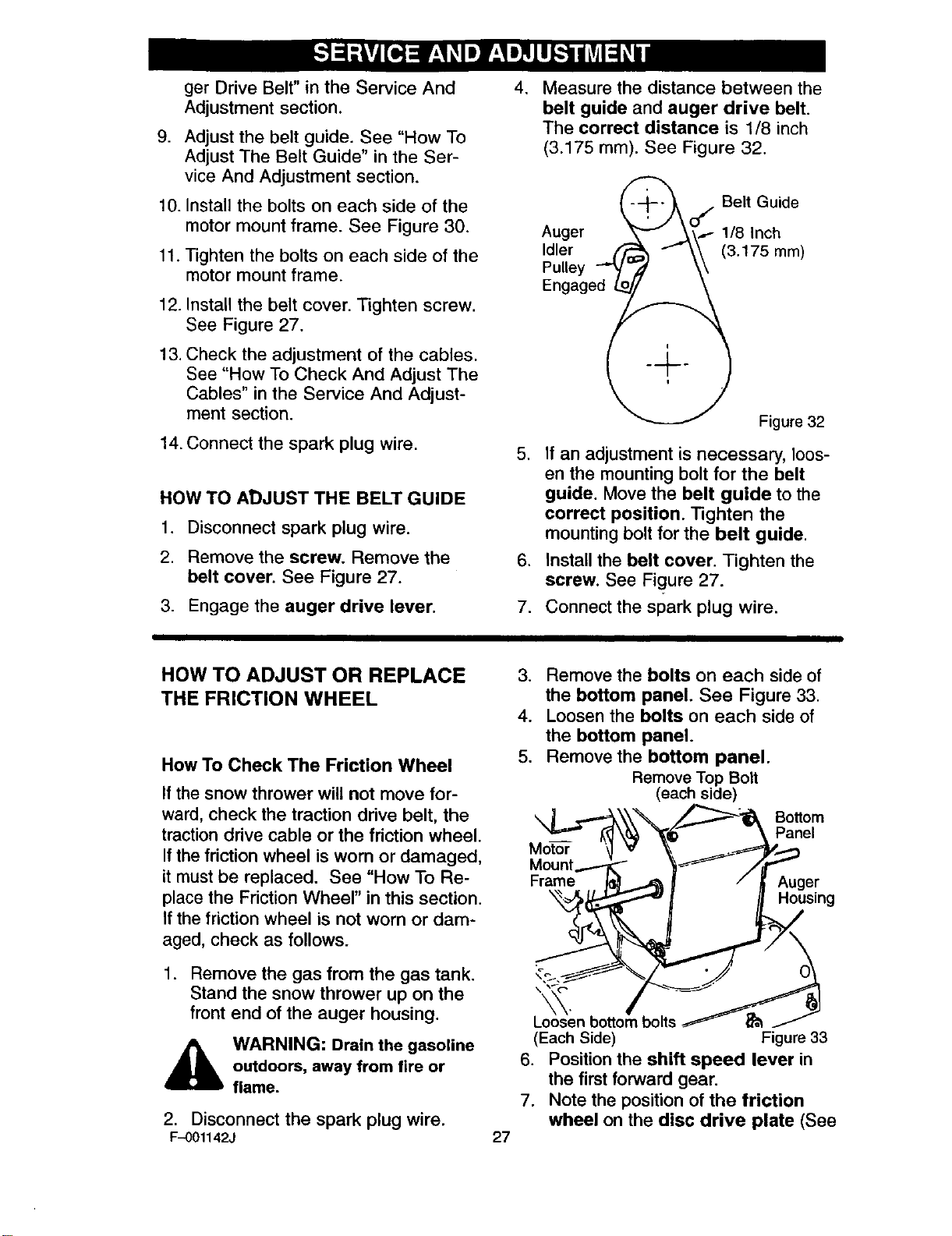
.Measure the distance between the
belt guide and auger drive belt.
The correct distance is 1/8 inch
(3.175 mm). See Figure 32.
.
.
7.
_- --_o /Belt Guide
Auger _ V'\ 1- 1/8 Inch
Idler ._"_ J"_\" (3.175mm)
Pulley "-_" \\
Engage__@_,_ .
Figure 32
If an adjustment is necessary, loos-
en the mounting bolt for the belt
guide. Move the belt guide to the
correct position. Tighten the
mounting bolt for the belt guide.
Install the belt cover. Tighten the
screw. See Figure 27.
Connect the spark plug wire.
HOW TO ADJUST OR REPLACE
THE FRICTION WHEEL
How To Check The Friction Wheel
If the snow thrower will not move for-
ward, check the traction drive belt, the
traction drive cable or the friction wheel.
If the friction wheel is worn or damaged,
it must be replaced. See "How To Re-
place the Friction Wheel" in this section.
If the friction wheel is not worn or dam-
aged, check as follows.
1. Remove the gas from the gas tank.
Stand the snow thrower up on the
front end of the auger housing.
_IL ARNING: Drain the gasoline
outdoors, away from fire or
flame.
2. Disconnect the spark plug wire.
F-001142J 27
3. Remove the bolts on each side of
the bottom panel. See Figure 33.
4. Loosen the bolts on each side of
the bottom panel.
5. Remove the bottom panel.
Remove Top Bolt
(each side)
FM°Uret''" {_ )/_e[ng
L_'sen bottom_ bolts _ _t
(Each Side) Figure 33
6. Position the shift speed lever in
the first forward gear.
7. Note the position of the friction
wheel on the disc drive plate (See
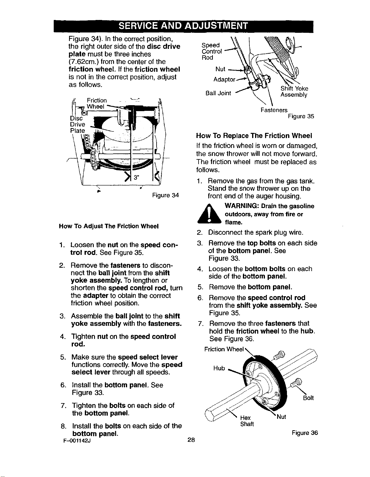
Figure 34). Inthecorrectposition,
the right outersideofthe disc drive
plate must be three inches
(7.62cm.) from the center of the
friction wheel. If the friction wheel
is not in the correct position, adjust
as follows.
Friction _"
heel
Disc
Drive
Plate
Figure 34
How To Adjust The Friction Wheel
1. Loosen the nut on the speed con-
trol rod. See Figure 35.
.Remove the fasteners to discon-
nect the ball joint from the shift
yoke assembly. To lengthen or
shorten the speed control rod, turn
the adapter to obtain the correct
friction wheel position.
3. Assemble the ball joint to the shift
yoke assembly with the fasteners.
4. Tighten nut on the speed control
rod.
5. Make sure the speed select lever
functions correctly. Move the speed
select lever through all speeds.
6. Install the bottom panel. See
Figure 33.
7. Tighten the bolts on each side of
the bottom panel.
S
Rod
Nut
Ball Joint Shift Yoke
Assembly
Fasteners Figure 35
How To Replace The Friction Wheel
If the friction wheel is worn or damaged,
the snow thrower will not move forward.
The friction wheel must be replaced as
follows.
1. Remove the gas from the gas tank.
Stand the snow thrower up on the
front end of the auger housing.
AARNING: Drain the gasoline
outdoors, away from fire or
flame.
2. Disconnect the spark plug wire.
3. Remove the top bolts on each side
of the bottom panel. See
Figure 33.
4. Loosen the bottom bolts on each
side of the bottom panel.
5. Remove the bottom panel.
6. Remove the speed control rod
from the shift yoke assembly. See
Figure 35.
7. Remove the three fasteners that
hold the friction wheel to the hub.
See Figure 36.
Friction
Hub
Bolt
Hex
Shaft
8. Install the bolts on each side of the
bottom panel. Figure 36
F-OO1142J 28
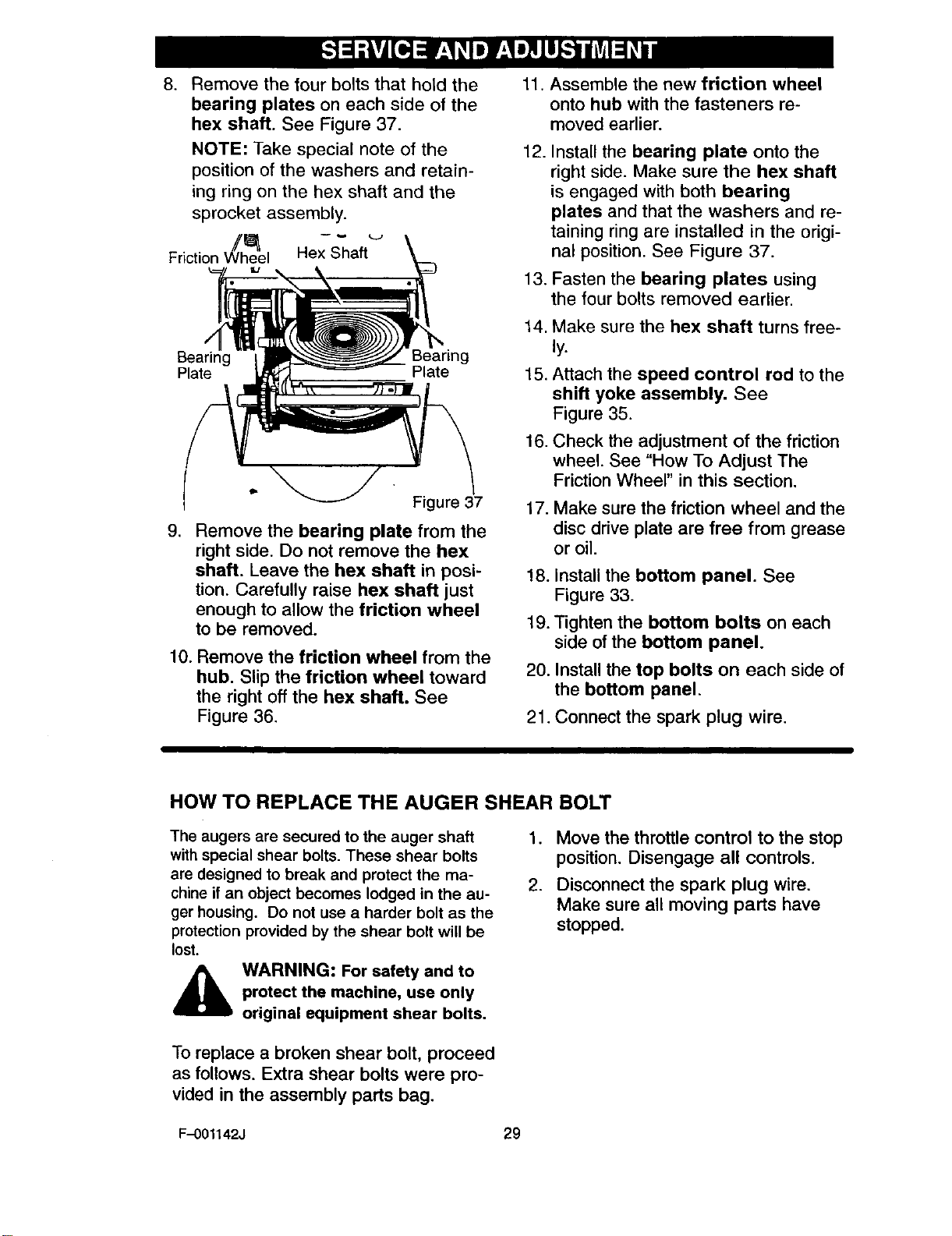
8. Remove the four bolts that hold the
bearing plates on each side of the
hex shaft. See Figure 37.
NOTE: Take special note of the
position of the washers and retain-
ing ring on the hex shaft and the
sprocket assembly.
Friction Wheel Hex Shaft
Bearing Bearing
Plate Plate
Figure 37
9. Remove the bearing plate from the
right side. Do not remove the hex
shaft. Leave the hex shaft in posi-
tion. Carefully raise hex shaft just
enough to allow the friction wheel
to be removed.
10. Remove the friction wheel from the
hub. Slip the friction wheel toward
the right off the hex shaft. See
Figure 36.
11. Assemble the new friction wheel
onto hub with the fasteners re-
moved earlier.
12. Install the bearing plate onto the
right side. Make sure the hex shaft
is engaged with both bearing
plates and that the washers and re-
taining ring are installed in the origi-
nal position. See Figure 37.
13. Fasten the bearing plates using
the four bolts removed earlier.
14.
15.
16.
Make sure the hex shaft turns free-
ly.
Attach the speed control rod to the
shift yoke assembly. See
Figure 35.
Check the adjustment of the friction
wheel. See "How To Adjust The
Friction Wheel" in this section.
17. Make sure the friction wheel and the
disc drive plate are free from grease
or oil.
!8. install the bottom panel. See
Figure 33.
19. Tighten the bottom bolts on each
side of the bottom panel.
20. Install the top bolts on each side of
the bottom panel.
21. Connect the spark plug wire.
HOW TO REPLACE THE AUGER SHEAR BOLT
The augers are secured to the auger shaft
with special shear bolts. These shear bolts
are designed to break and protect the ma-
chine if an object becomes lodged in the au-
ger housing. Do not use a harder bolt as the
protection provided by the shear bolt will be
lost.
,_ WARNING: For safety and to
protect the machine, use only
original equipment shear bolts.
.
2.
Move the throttle control to the stop
position. Disengage all controls.
Disconnect the spark plug wire.
Make sure all moving parts have
stopped.
To replace a broken shear bolt, proceed
as follows. Extra shear bolts were pro-
vided in the assembly parts bag.
F-001142J 29
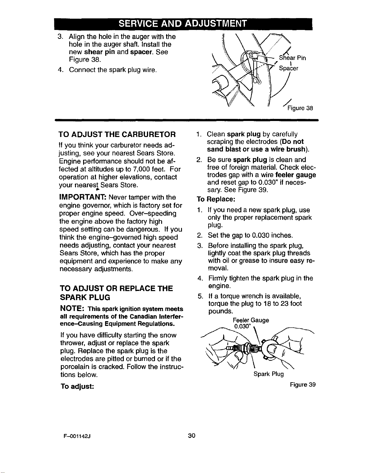
.Align the hole in the auger with the
hole in the auger shaft. Install the
new shear pin and spacer. See
Figure 38.
4. Connect the spark plug wire.
_ar Pin
_ _2cer
_Figure 38
TO ADJUST THE CARBURETOR
If you think your carburetor needs ad-
justing, see your nearest Sears Store.
Engine performance should not be af-
fected at altitudes up to 7,000 feet. For
operation at higher elevations, contact
your nearest Sears Store.
lib
IMPORTANT: Never tamper with the
engine governor, which is factory set for
proper engine speed. Over-speeding
the engine above the factory high
speed setting can be dangerous. If you
think the engine-governed high speed
needs adjusting, contact your nearest
Sears Store, which has the proper
equipment and experience to make any
necessary adjustments.
TO ADJUST OR REPLACE THE
SPARK PLUG
NOTE: This spark ignition system meets
all requirements of the Canadian Interfer-
ence-Causing Equipment Regulations.
If you have difficulty starting the snow
thrower, adjust or replace the spark
plug. Replace the spark plug is the
electrodes are pitted or burned or if the
porcelain is cracked. Follow the instruc-
tions below.
To adjust:
.
.
To
1.
.
3.
.
5.
Clean spark plug by carefully
scraping the electrodes (Do not
sand blast or use awire brush).
Be sure spark plug is clean and
free of foreign material. Check elec-
trodes gap with a wire feeler gauge
and reset gap to 0.030" if neces-
sary. See Figure 39.
Replace:
If you need a new spark plug, use
only the proper replacement spark
plug.
Set the gap to 0.030 inches.
Before installing the spark plug,
lightly coat the spark plug threads
with oil or grease to insure easy re-
moval.
Firmly tighten the spark plug in the
engine.
If a torque wrench is available,
torque the plug to 18 to 23 foot
pounds. Feeler Gauge
0.030"
Spark Plug
Figure 39
F-O01142J 30
,_ WARNING: Never store your
snow thrower indoors or in
an enclosed, poorly venti-
lated area. If gasoline remains in the
tank, fumes may reach an open
flame, spark or pilot light from a fur-
nace, water heater, clothes dryer,
cigarette, etc.
NOTE: To prevent engine damage (if
snow thrower is not used for more
than 30 days) follow the steps below.
SNOW THROWER
1. Thoroughly clean the snow thrower.
2. Lubricate all lubrication points. See
the Maintenance section.
3. Be sure that all nuts, bolts and
screws_are securely fastened. In-
spect all visible moving parts for
damage, breakage and wear. Re-
place if necessary.
4. Touch up all rusted or chipped paint
surfaces; sand lightly before paint-
ing.
5. Cover the bare metal parts of the
blower housing auger and the im-
peller with rust preventative, such
as a spray lubricant.
NOTE: A yearly checkup or tune-up by
a Sears service center is a good way of
ensuring that your snow thrower will
provide maximum performance for the
next season.
ENGINE
_b ARNING: Drain the gaso-
line outdoors, away from
fire or flame.
Gasoline must be removed or treated to
prevent gum deposits from forming in
the fuel tank, filter, hose, and carburetor
during storage. Also, during storage al-
cohol blended gasoline that uses etha-
nol or methanol (sometimes called
gasohol) attracts water. It acts on the
gasoline to form acids which damage
the engine.
F-001142J
.
.
31
.
,
5.
To remove gasoline, run the engine
until the fuel tank is empty and the
engine stops.
If you do not remove the gasoline,
use fuel stabilizer supplied with unit
or purchase Craftsman Fuel Stabi-
lizer No. 3550. Add fuel stabilizer to
any gasoline left in the tank to mini-
mize gum deposits and acids. If the
fuel tank is almost empty, mix stabi-
lizer with fresh gasoline in a sepa-
rate container and add some to the
fuel tank.
Always follow the instruction on the
stabilizer container. After the stabi-
lizer is added to the fuel tank, run
the engine at least ten minutes to
allow the mixture to reach the car-
buretor.
Change the engine oil.
Lubricate the piston/cylinder area.
First, remove the spark plug and
squirt a few drops of clean engine
oil into the spark plug hole. Next,
cover the spark plug hole with a rag
to absorb oil spray. Then, pull two or
three times on the recoil starter rope
to rotate the engine. Finally, install
the spark plug and attach the spark
plug wire.
OTHER
1. If possible, store your snow thrower
indoors and cover it to give protec-
tion from dust and dirt.
2.
.
If the machine must be stored out-
doors, block up the snow thrower to
be sure the entire machine is off the
ground.
Cover the snow thrower with a suit-
able protective cover that does not
retain moisture. Do not use plastic.
IMPORTANT: Never cover snow
thrower while engine and exhaust areas
are still warm.
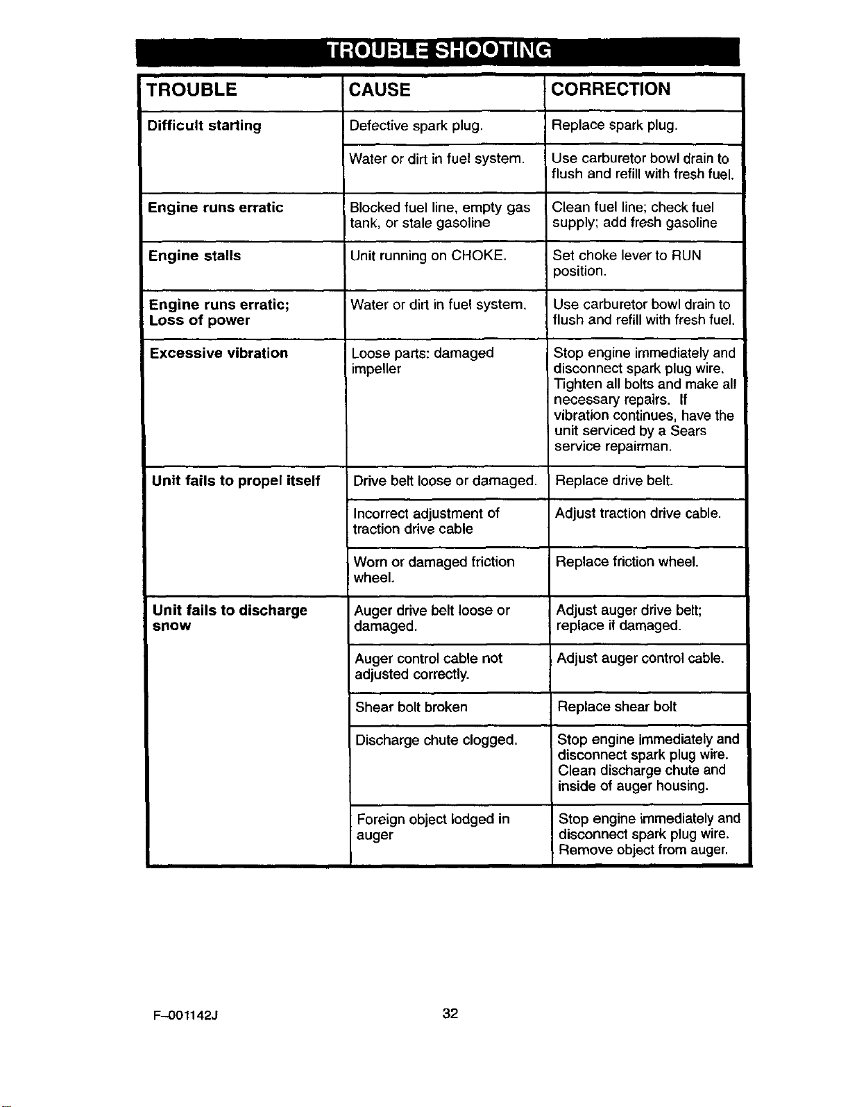
TROUBLE CAUSE CORRECTION
Difficult starting Replace spark plug.Defective spark plug.
!Water or dirt in fuel system. Use carburetor bowl drain to
flush and refill with fresh fuel.
Engine runs erratic Blocked fuel line, empty gas Clean fuel line; check fuel
tank, or stale gasoline supply; add fresh gasoline
Engine stalls Unit running on CHOKE. Set choke lever to RUN
3osition.
Engine runs erratic; Water or dirt in fuel system. Use carburetor bowl drain to
Loss of power flush and refill with fresh fuel.
Excessive vibration
Unit fails to propel itself
Unit fails to discharge
snow
Loose parts: damaged
impeller Stop engine immediately and
disconnect spark plug wire.
Tighten all bolts and make all
necessary repairs. If
vibration continues, have the
unit serviced by a Sears
service repairman.
Drive belt loose or damaged. Replace drive belt.
Incorrect adjustment of Adjust traction drive cable.
traction drive cable
Worn or damaged friction Replace friction wheel.
wheel.
Auger drive belt loose or
damaged.
Auger control cable not
adjusted correctly.
Shear bolt broken
Discharge chute clogged.
Foreign object lodged in
auger
Adjust auger drive belt;
replace if damaged.
Adjust auger control cable.
Replace shear bolt
Stop engine immediately and
disconnect spark plug wire.
Clean discharge chute and
inside of auger housing.
Stop engine immediately and
disconnect spark plug wire.
Remove object from auger.
F--O01142J 32
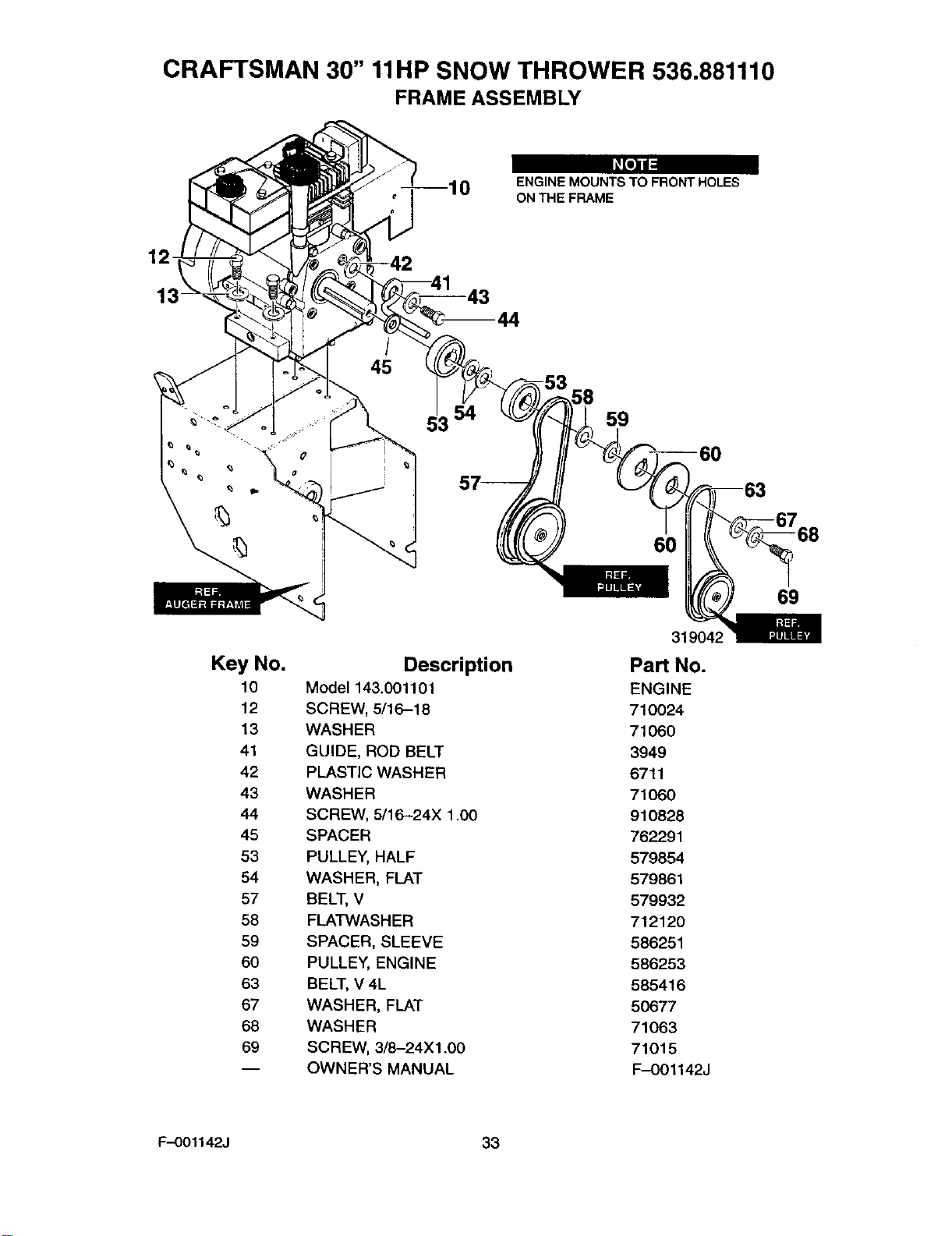
CRAFTSMAN 30" 11liP SNOW THROWER 536.881110
FRAME ASSEMBLY
O[O]ll
110 ENGINE MOUNTS TO FRONT HOLES
ON THE FRAME
12
14
45
53 59
60
Key No.
10
12
13
41
42
43
44
45
53
54
57
58
59
6O
63
67
68
69
Description
Model 143.001101
SCREW, 5/16-18
WASHER
GUIDE, ROD BELT
PLASTIC WASHER
WASHER
SCREW, 5/16-24X 1.00
SPACER
PULLEY, HALF
WASHER, FLAT
BELT, V
FLATWASHER
SPACER, SLEEVE
PULLEY, ENGINE
BELT, V 4L
WASHER, FLAT
WASHER
SCREW, 3/8-24X1.00
OWNER'S MANUAL
319042
Part No.
ENGINE
710024
71060
3949
6711
71060
910828
762291
579854
579861
579932
712120
586251
586253
585416
50677
71063
71015
F-O01142J
69
F-001142J 33
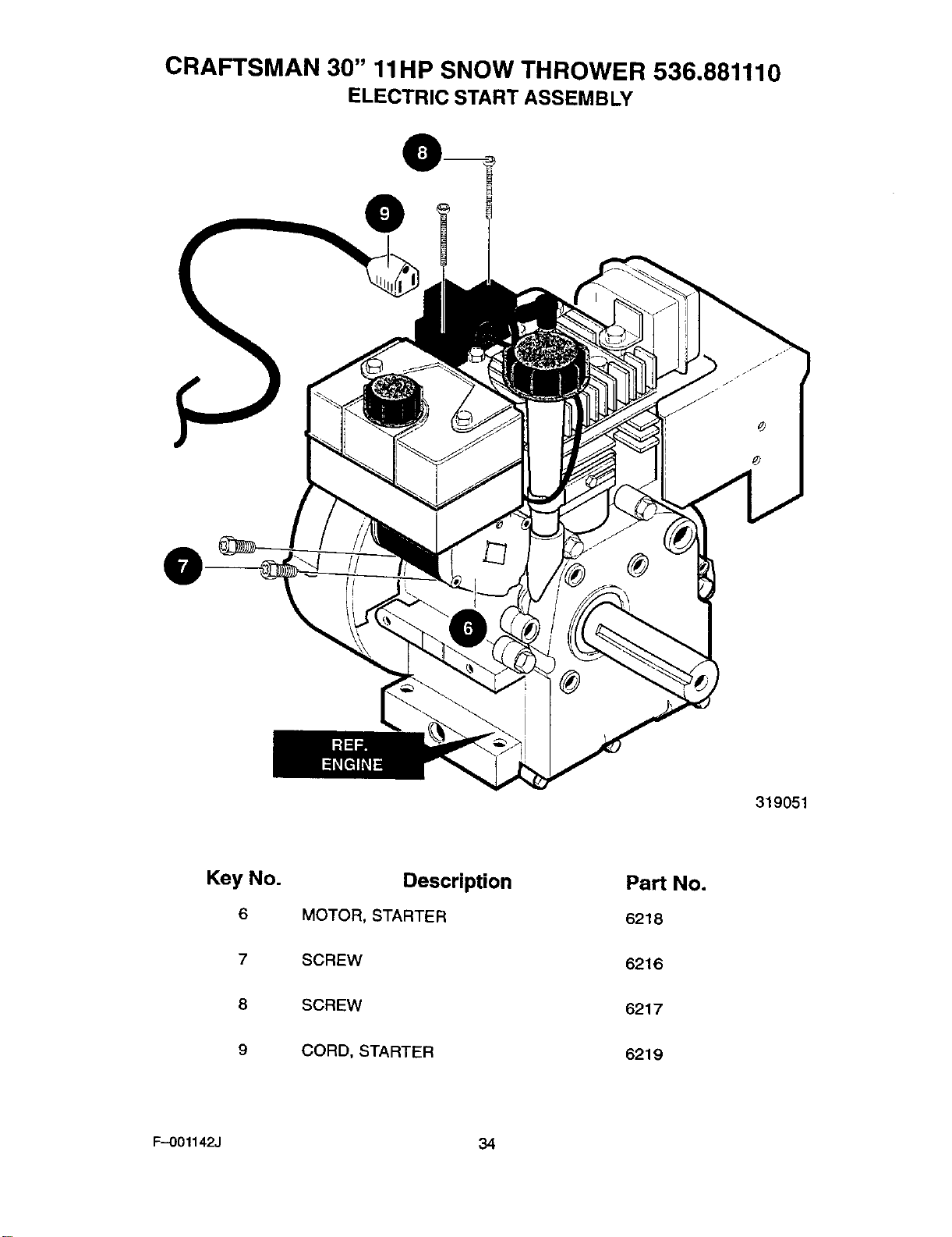
CRAFTSMAN 30" 11liP SNOW THROWER 536.881110
ELECTRIC START ASSEMBLY
@
319051
Key No. Description Part No.
6 MOTOR, STARTER 6218
7SCREW 6216
8 SCREW 6217
9 CORD, STARTER 6219
F--001142J 34
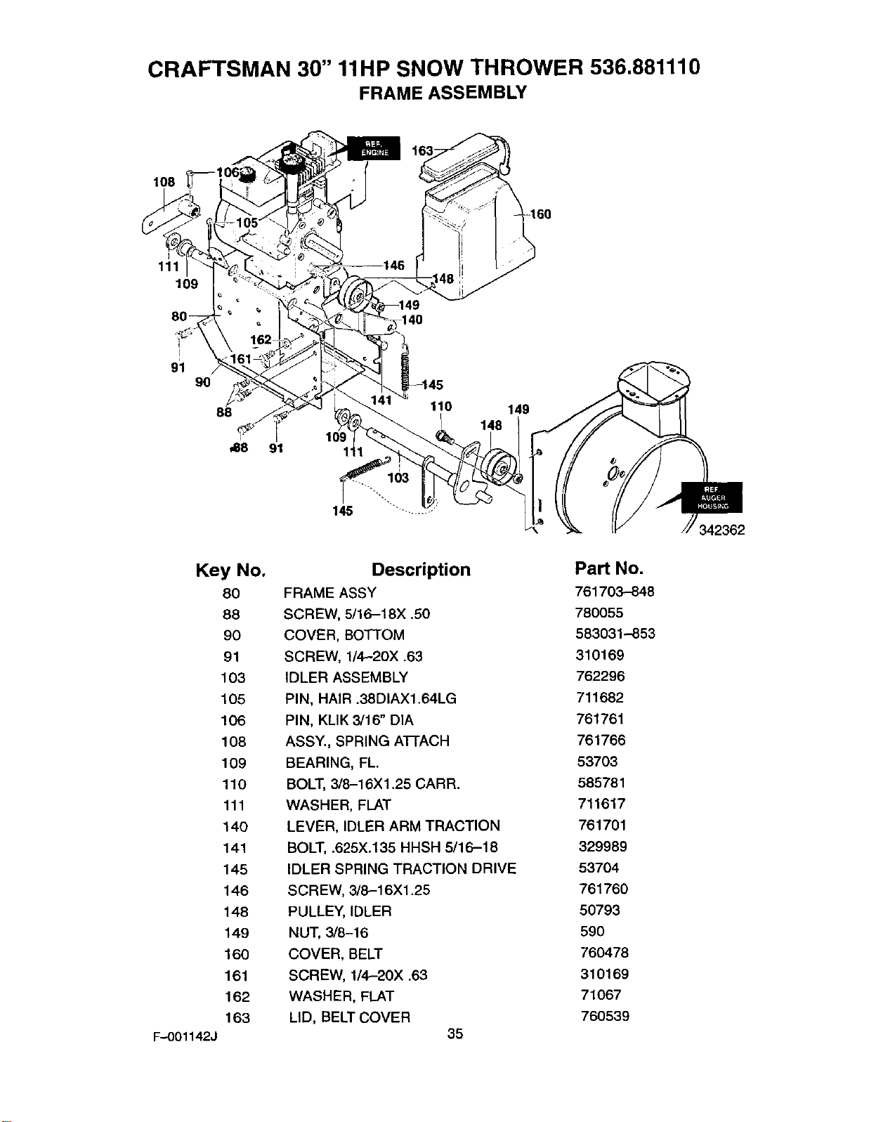
CRAFTSMAN 30" 11liP SNOW THROWER 536.881110
FRAME ASSEMBLY
108
16
111
109
91 90
88
_8 91
Key No.
F-O01142J
8O
88
90
91
103
105
106
108
109
110
111
140
141
145
146
148
149
160
161
162
163
140
148
1"
Description Part No.
FRAME ASSY 761703-848
SCREW, 5/16--18X .50 780055
COVER, BOTTOM 583031-853
SCREW, 1/4--2OX .63 310169
IDLER ASSEMBLY 762296
PIN, HAIR .38DIAX1.64LG 711682
PIN, KLIK 3/16' DIA 761761
ASSY., SPRING AI-FACH 761766
BEARING, FL. 53703
BOLT, 3/8-16Xl .25 CARR. 585781
WASHER, FLAT 711617
LEVER, IDLER ARM TRACTION 761701
BOLT, .625X,135 HHSH 5/16-18 329989
IDLER SPRING TRACTION DRIVE 53704
SCREW, 3/8-16Xl.25 761760
PULLEY, IDLER 50793
NUT, 3/8-16 590
COVER, BELT 760478
SCREW, 1/4.-20X .63 310169
WASHER, FLAT 71067
LID, BELT COVER 760539
35
342362
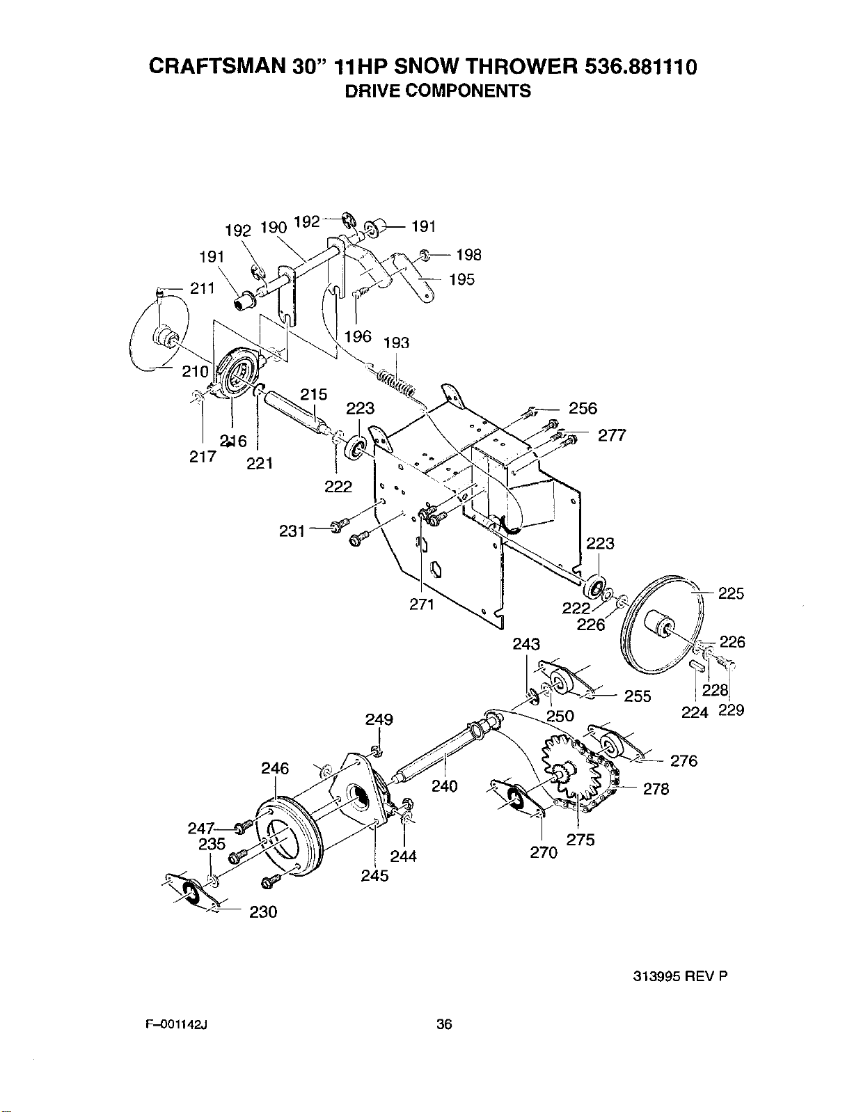
CRAFTSMAN 30" 11liP SNOW THROWER 536.881110
DRIVE COMPONENTS
192 190 191
191
211 _ 195
196 193
217 221
215 223
222
256
277
231 223
271 -- 225
249 250 255 224 229
246 240
276
278
235 244
245
275
270
230
313995 REV P
F.-001142J 36
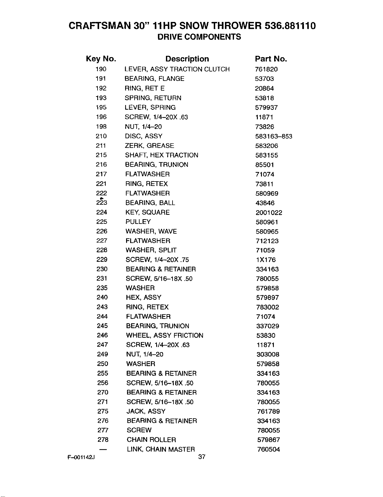
CRAFTSMAN 30" 11liP SNOW THROWER 536.881110
DRIVE COMPONENTS
Key No.
190
191
192
193
195
196
198
210
211
218
216
217
221
222
ii.
223
224
225
226
227
228
229
230
231
235
240
243
244
245
246
247
249
25O
255
256
270
271
275
276
277
278
F-001142J
Description Part No.
LEVER, ASSY TRACTION CLUTCH 761820
REARING, FLANGE 53703
RING, RET E 20864
SPRING, RETURN 53818
LEVER, SPRING 579937
SCREW, 1/4-20X .63 11871
NUT, 1/4-20 73826
DISC, ASSY 583163-853
ZERK, GREASE 583206
SHAFT, HEX TRACTION 583155
REARING, TRUNION 85501
FLATWASHER 71074
RING, RETEX 73811
FLATWASHER 580969
REARING, BALL 43846
KEY, SQUARE 2001022
PULLEY 580961
WASHER, WAVE 580965
FLATWASHER 712123
WASHER, SPLIT 71059
SCREW, 1/4-20X .75 1X176
REARING & RETAINER 334163
SCREW, 5/16-18X .50 780055
WASHER 579858
HEX, ASSY 579897
RING, RETEX 783002
FLATWASHER 71074
BEARING, TRUNION 337029
WHEEL, ASSY FRICTION 53830
SCREW, 1/4-20X .63 11871
NUT, 1/4-20 303008
WASHER 579858
BEARING & RETAINER 334163
SCREW, 5/16-18X .50 780055
BEARING & RETAINER 334163
SCREW, 5/1 6-18X .50 780055
JACK, ASSY 761789
BEARING & RETAINER 334163
SCREW 780055
CHAIN ROLLER 579867
LINK, CHAIN MASTER 760504
37
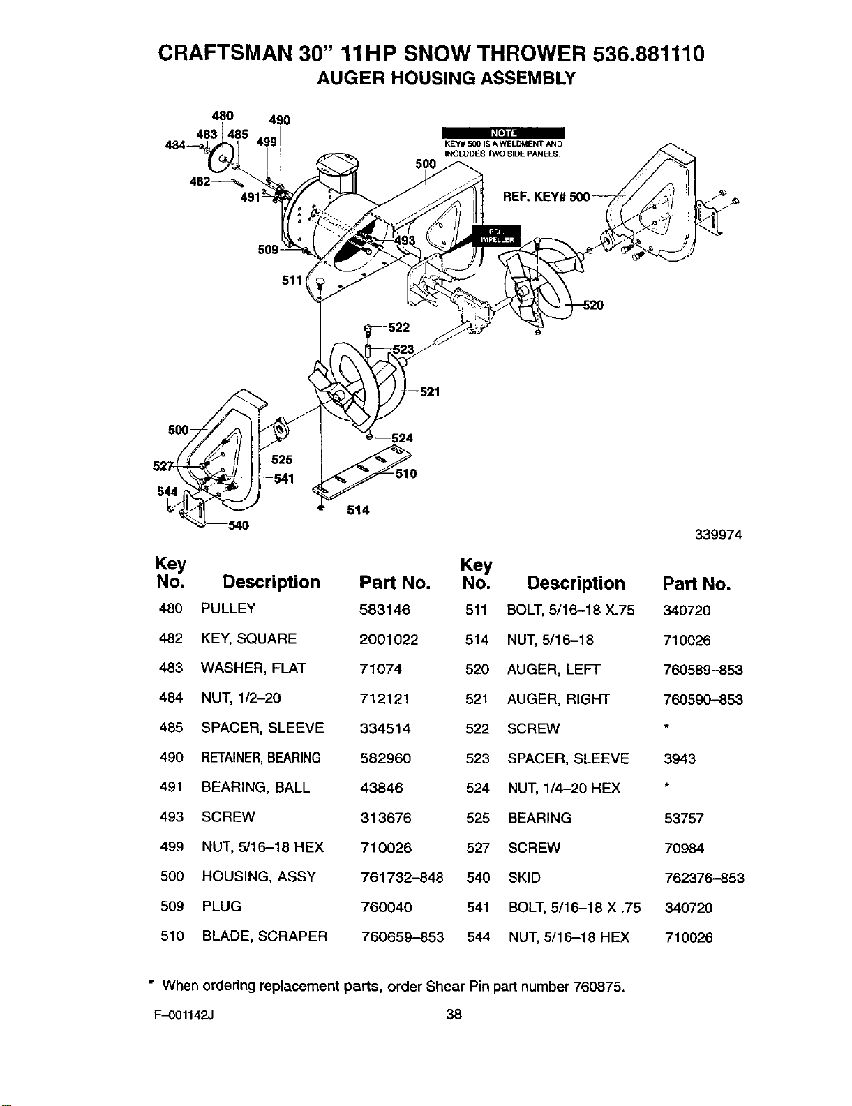
CRAFTSMAN 30" 11liP SNOW THROWER 536.881110
AUGER HOUSING ASSEMBLY
48O 490
483
482% 500
KEY# 5(_ IS A WELDMENT AND
INCLUDES TWO SIDE PANELS.
/"_"
509 -
511
500- 524
544 514
Key Key
No. Description Part No. No. Description
480 PULLEY 583146 511 BOLT, 5/16-18 X.75
482 KEY, SQUARE 2001022 514 NUT, 5/16-18
483 WASHER, FLAT 71074 520 AUGER, LEFT
484 NUT, 1/2-20 712121 521 AUGER, RIGHT
485 SPACER, SLEEVE 334514 522 SCREW
490 RETAINER,BEARING 582960 523 SPACER, SLEEVE
491 BEARING, BALL 43846 524 NUT, 1/4-20 HEX
493 SCREW 313676 525 BEARING
499 NUT, 5/16-18 HEX 710026 527 SCREW
500 HOUSING, ASSY 761732-848 540 SKID
509 PLUG 760040 541 BOLT, 5/16-18 X .75
510 BLADE, SCRAPER 760659-853 544 NUT, 5/16-18 HEX
* When ordering replacement parts, order Shear Pin part number 760875.
F-001142J 38
339974
Part No.
340720
710026
760589-853
760590-853
3943
53757
70984
762376-853
340720
710026
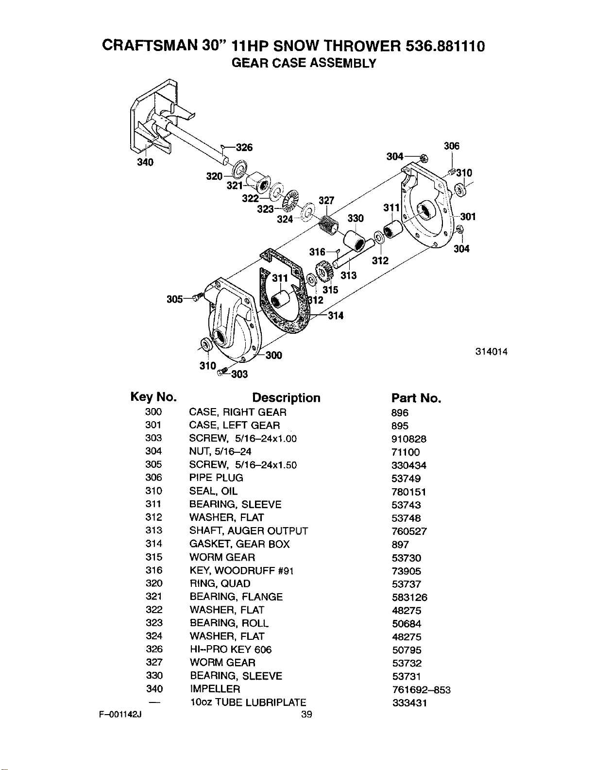
CRAFTSMAN 30" 11liP SNOW THROWER 536.881110
GEAR CASE ASSEMBLY
340
321
316--
313
315
33O 311
312
306
304
310 -30O 314014
Key No.
300
301
3O3
304
305
306
310
311
312
313
314
315
316
320
321
322
323
324
326
327
330
340
F-OO1142J
Description
CASE, RIGHT GEAR
CASE, LEFT GEAR
SCREW, 5/16-24xl.00
NUT, 5/16-24
SCREW, 5/16-24xl.50
PIPE PLUG
SEAL, OIL
SEARING, SLEEVE
WASHER, FLAT
SHAFT, AUGER OUTPUT
GASKET, GEAR BOX
WORM GEAR
KEY, WOODRUFF #91
RING, QUAD
BEARING, FLANGE
WASHER, FLAT
BEARING, ROLL
WASHER, FLAT
HI-PRO KEY 606
WORM GEAR
BEARING, SLEEVE
IMPELLER
10oz TUBE LUBRIPLATE39
Part No.
896
895
910828
71100
330434
53749
780151
53743
53748
760527
897
53730
73905
53737
583126
48275
50684
48275
50795
53732
53731
761692-853
333431
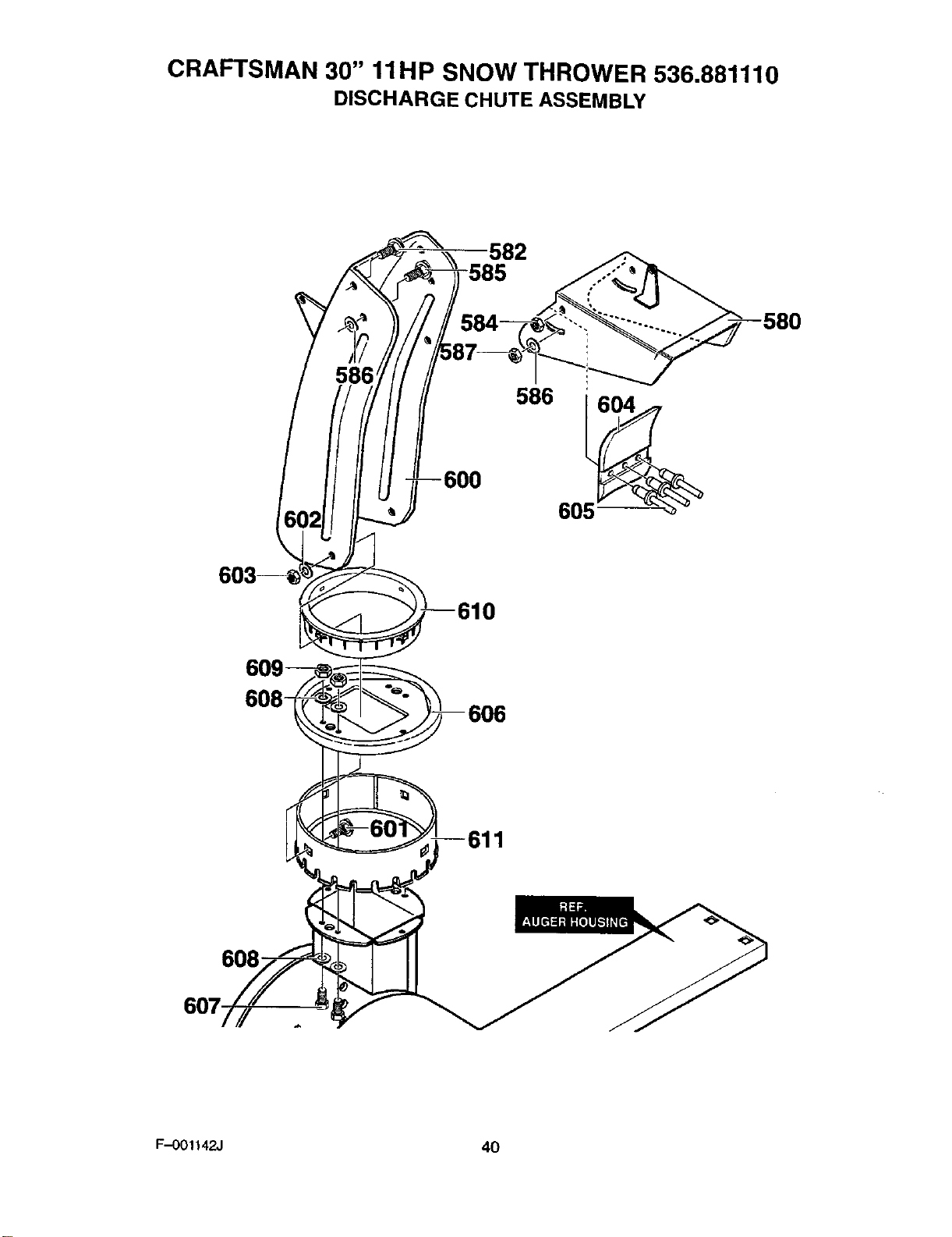
CRAFTSMAN 30" 11liP SNOW THROWER 536.881110
DISCHARGE CHUTE ASSEMBLY
582
586'
6O8
F..-001142J 40
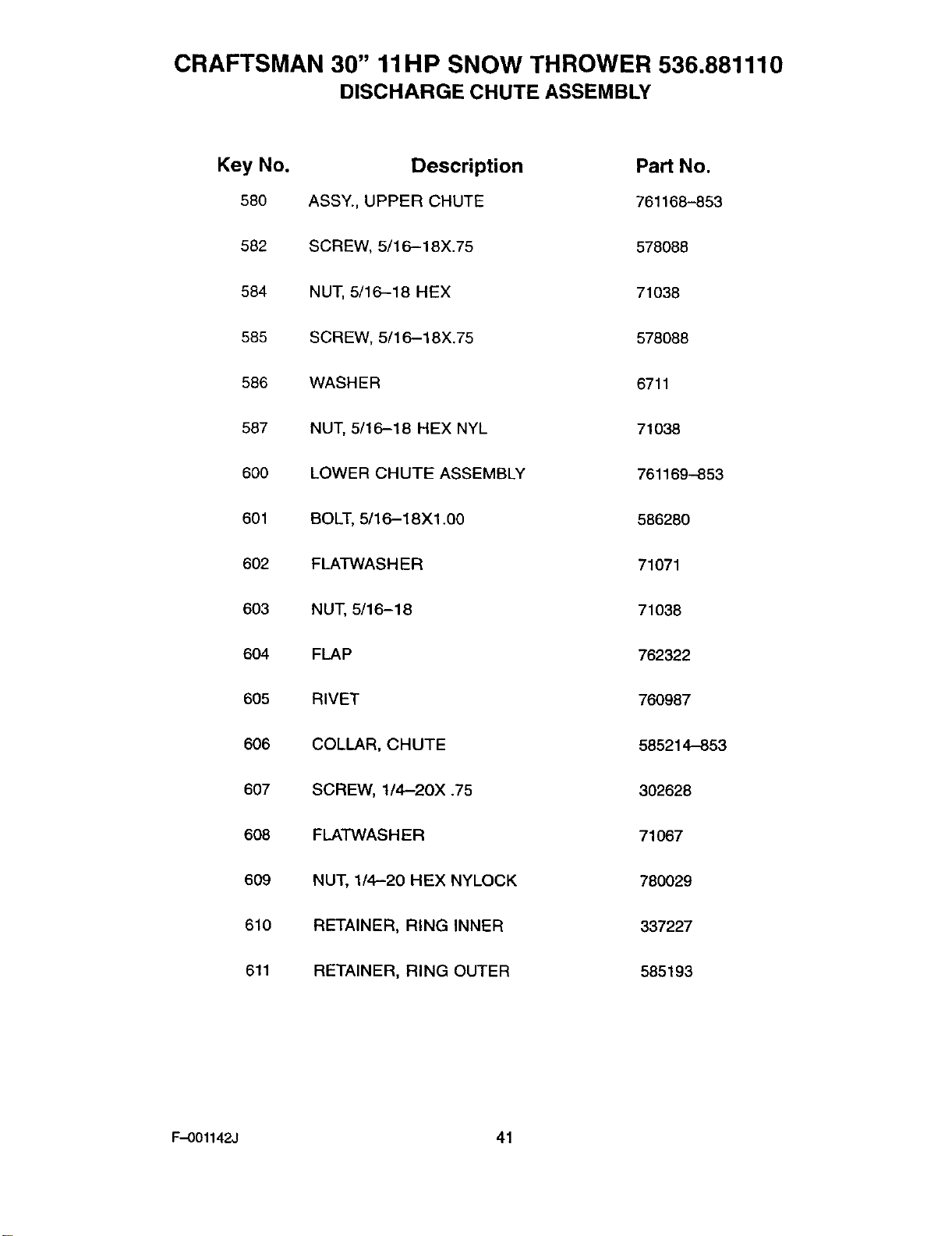
CRAFTSMAN 30" 11liP SNOW THROWER 536.881110
DISCHARGE CHUTE ASSEMBLY
Key No. Description Part No.
580 ASSY., UPPER CHUTE 761168-853
582 SCREW, 5/16-18X.75 578088
584 NUT, 5/16-18 HEX 71038
585 SCREW, 5/16-18X.75 578088
586 WASH ER 6711
587 NUT, 5/16-18 HEX NYL 71038
600 LOWER CHUTE ASSEMBLY 761169-853
601 BOLT, 5/16-18X1.00 586280
602 FLATWASHER 71071
603 NUT, 5/16-18 71038
604 FLAP 762322
605 RIVET 760987
606 COLLAR, CHUTE 585214-853
607 SCREW, 1/4-20X .75 302628
608 FLATWAS HER 71067
609 NUT, 1/4-20 HEX NYLOCK 780029
610 RETAINER, RING INNER 337227
611 RETAINER, RING OUTER 585193
F-001142J 41
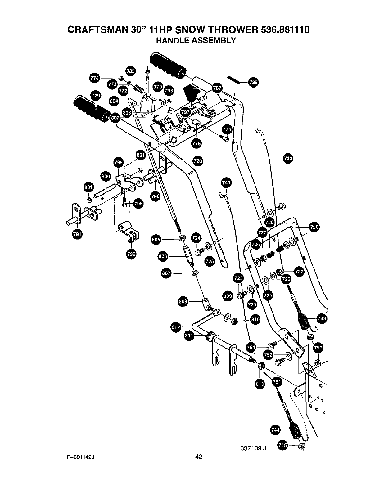
CRAFTSMAN 30" 11liP SNOW THROWER 536.881110
HANDLE ASSEMBLY
@®O
@
O@
@@e
@
@
337139 J
F-O01142J 42
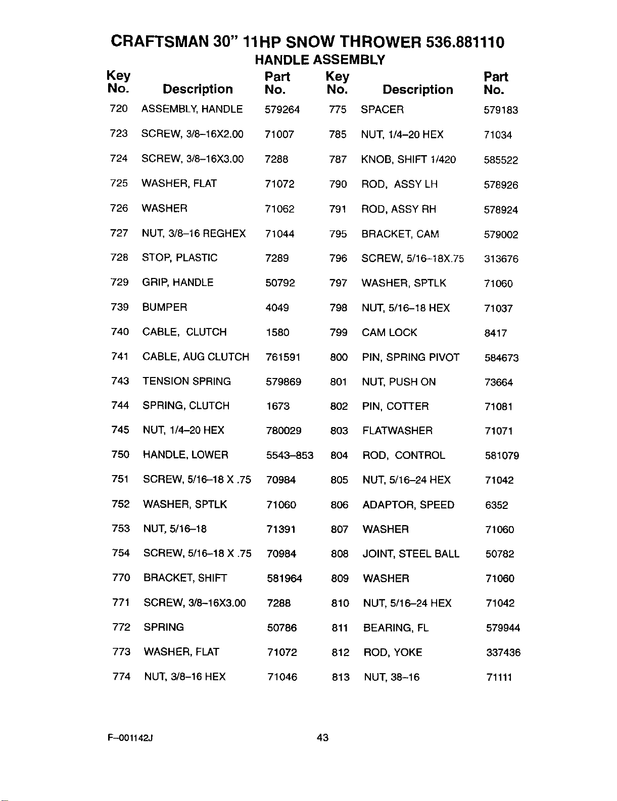
CRAFTSMAN 30" 11liP SNOW THROWER 536.881110
HANDLE ASSEMBLY
Key Part Key Part
No. Description No. No. Description No.
720 ASSEMBLY, HANDLE 579264 775 SPACER 579183
723 SCREW, 3/8-16X2.00 71007 785 NUT, 1/4-20 HEX 71034
724 SCREW, 3/8-16X3.00 7288 787 KNOB, SHIFT 1/420 585522
725 WASHER, FLAT 71072 790 ROD, ASSY LH 578926
726 WASHER 71062 791 ROD, ASSY RH 578924
727 NUT, 3/8-16 REGHEX 71044 795 BRACKET, CAM 579002
728 STOP, PLASTIC 7289 796 SCREW, 5/16-18X.75 313676
729 GRIP, HANDLE 50792 797 WASHER, SPTLK 71060
739 BUMPER 4049 798 NUT, 5/16-18 HEX 71037
740 CABLE, CLUTCH 1580 799 CAM LOCK 8417
741 CABLE, AUG CLUTCH 761591 800 PIN, SPRING PIVOT 584673
743 TENSION SPRING 579869 801 NUT, PUSH ON 73664
744 SPRING, CLUTCH 1673 802 PIN, COTTER 71081
745 NUT, 1/4-20 HEX 780029 803 FLATWASHER 71071
750 HANDLE, LOWER 5543-853 804 ROD, CONTROL 581079
751 SCREW, 5/16-18 X .75 70984 805 NUT, 5/16-24 HEX 71042
752 WASHER, SPTLK 71060 806 ADAPTOR, SPEED 6352
753 NUT, 5/16-18 71391 807 WASHER 71060
754 SCREW, 5/16-18 X .75 70984 808 JOINT, STEEL BALL 50782
770 BRACKET, SHIFT 581964 809 WASHER 71060
771 SCREW, 3/8--16X3.00 7288 810 NUT, 5/16-24 HEX 71042
772 SPRING 50786 811 BEARING, FL 579944
773 WASHER, FLAT 71072 812 ROD, YOKE 337436
774 NUT, 3/8-16 HEX 71046 813 NUT, 38-16 71111
F-O01142J 43
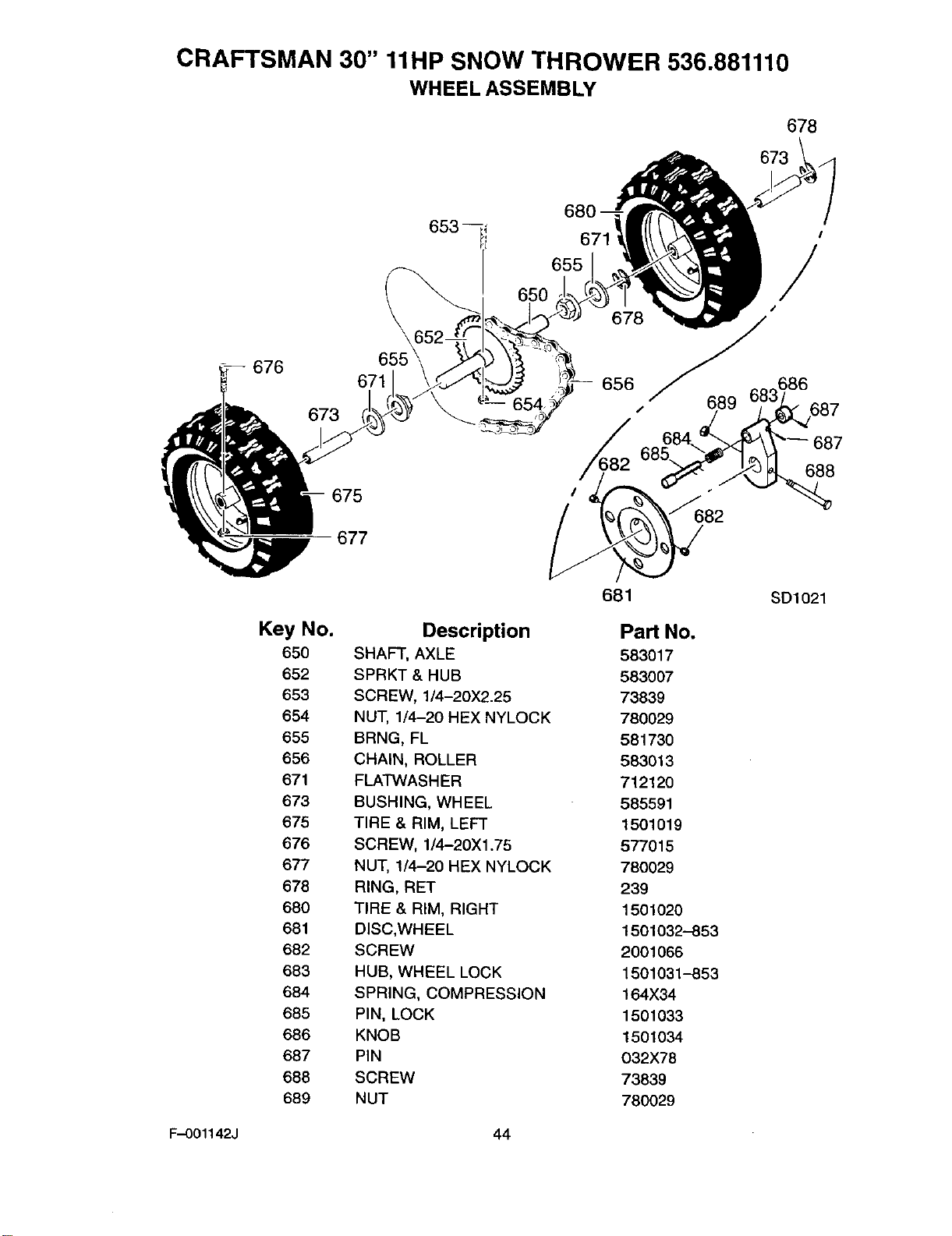
CRAFTSMAN 30" 11liP SNOW THROWER 536.881110
WHEELASSEMBLY
678
673
676 671
673
675
677
I
650 655 /
/
678_
656 686
654 ¢ 689
684 687
685\ 688
Key No.
65O
652
653
654
655
656
671
673
675
676
677
678
680
681
682
683
684
685
686
687
688
689
Description
SHAFT, AXLE
SPRKT & HUB
SCREW, 1/4-20X2.25
NUT, 1/4-20 HEX NYLOCK
BRNG, FL
CHAIN, ROLLER
FLATWASHER
BUSHING, WHEEL
TIRE & RIM, LEFT
SCREW, 1/4-20Xl .75
NUT, 1/4-20 HEX NYLOCK
RING, RET
TIRE & RIM, RIGHT
DISC,WHEEL
SCREW
HUB, WHEEL LOCK
SPRING, COMPRESSION
PIN, LOCK
KNOB
PIN
SCREW
NUT
681 SD1021
Part No.
583017
583007
73839
780029
581730
583013
712120
585591
1501019
577015
780029
239
1501020
1501032--853
2001066
1501031-853
164X34
1501033
1501034
O32X78
73839
780029
F-O01142J 44
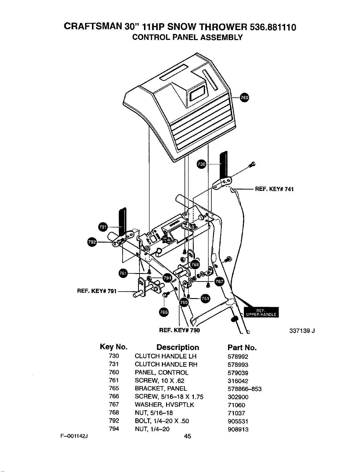
CRAFTSMAN 30" 11liP SNOW THROWER 536.881110
CONTROL PANEL ASSEMBLY
741
REF. KEY#'
F--O01142J
Key No.
730
731
760
761
765
766
767
768
792
794
@
REF. KEY# 790
Description Part No.
CLUTCH HANDLE LH 578992
CLUTCH HANDLE RH 578993
PANEL, CONTROL 579039
SCREW, 10 X .62 316042
BRACKET, PANEL 578866-853
SCREW, 5/16-18 X 1.75 302900
WASHER, HVSPTLK 71060
NUT, 5/16-18 71037
BOLT, 1/4-20 X .50 905531
NUT, 1/4-20 908913
45
337139 J
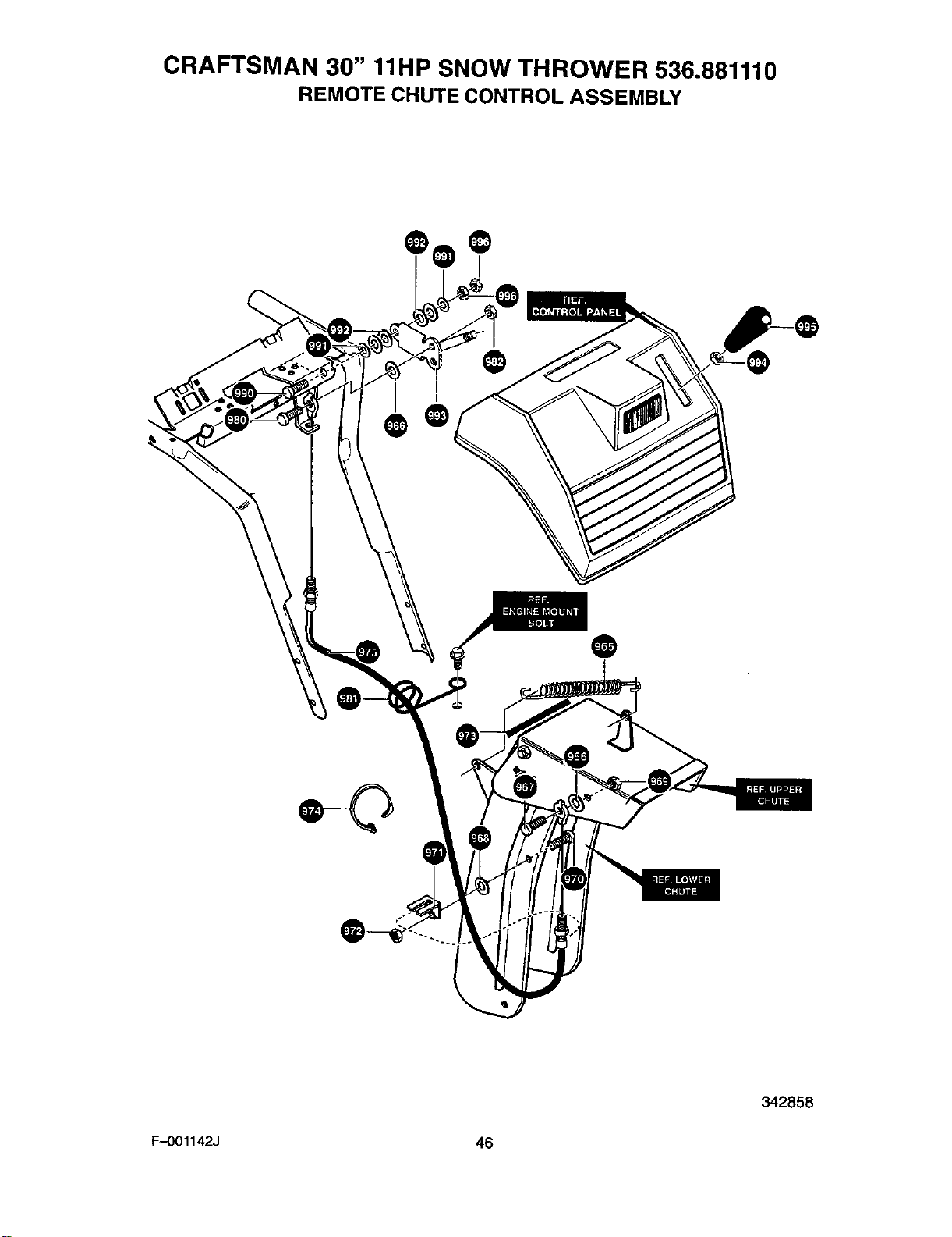
CRAFTSMAN 30" 11liP SNOW THROWER 536.881110
REMOTE CHUTE CONTROL ASSEMBLY
@ @
@
F-O01142J 46
342858
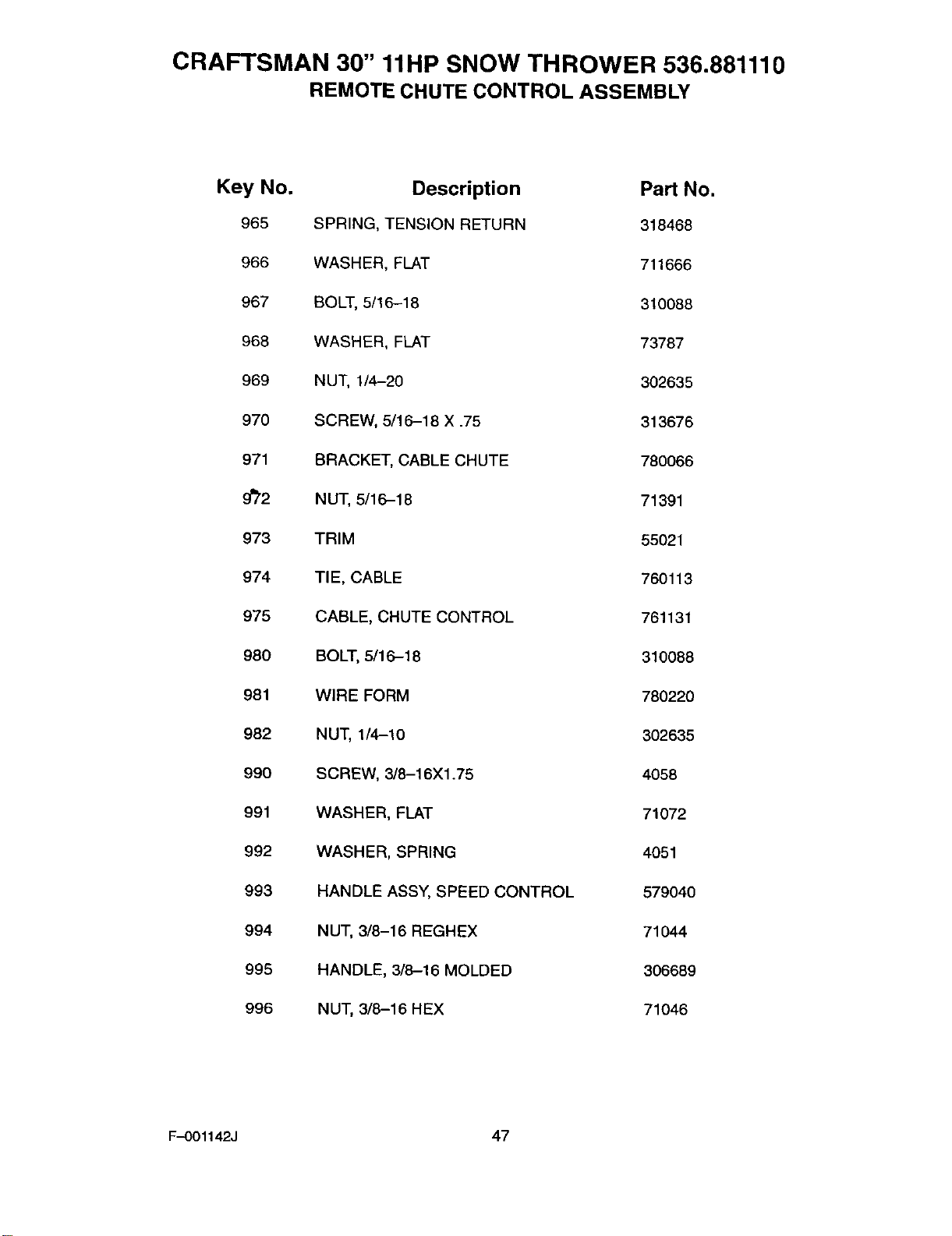
CRAFTSMAN 30" 11HP SNOW THROWER 536.881110
REMOTE CHUTE CONTROL ASSEMBLY
Key No.
965
966
967
968
969
970
971
9_'2
973
974
975
98O
981
982
990
991
992
993
994
995
996
Description Part No.
SPRING, TENSION RETURN 318468
WASHER, FLAT 711666
BOLT, 5/16-18 310088
WASHER, FLAT 73787
NUT, 1/4-20 302635
SCREW, 5/16-18 X .75 313676
BRACKET, CABLE CHUTE 780066
NUT, 5/16-18 71391
TRIM 55021
TI E, CABLE 760113
CABLE, CHUTE CONTROL 761131
BOLT, 5/16-18 310088
WIRE FORM 780220
NUT, 1/4-10 302635
SCREW, 3/8-16X1.75 4058
WASHER, FLAT 71072
WASHER, SPRING 4051
HANDLE ASSY, SPEED CONTROL 579040
NUT, 3/8-16 REGHEX 71044
HANDLE, 3/8-16 MOLDED 306689
NUT, 3/8-16 HEX 71046
F-O01142J 47
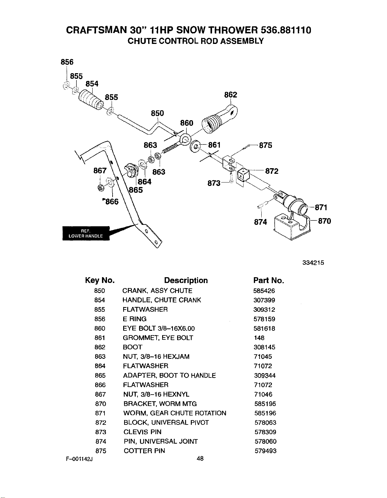
CRAFTSMAN 30" 11liP SNOW THROWER 536.881110
CHUTE CONTROL ROD ASSEMBLY
856
.855 854
855
850 860
862
867
863
I
863
864
874
F-OO1142J
Key No.
850
854
855
856
860
861
862
863
864
865
866
867
870
871
872
873
874
875
Description
CRANK, ASSY CHUTE
HANDLE, CHUTE CRANK
FLATWASHER
E RING
EYE BOLT 3/8-16X6.00
GROMMET, EYE BOLT
BOOT
NUT, 3/8-16 HEXJAM
FLATWASHER
ADAPTER, BOOT TO HANDLE
FLATWASHER
NUT, 3/8-16 HEXNYL
BRACKET, WORM MTG
WORM, GEAR CHUTE ROTATION
BLOCK, UNIVERSAL PIVOT
CLEVIS PIN
PIN, UNIVERSAL JOINT
COTTER PiN 48
Part No.
585426
307399
309312
578159
581618
148
308145
71045
71072
309344
71072
71046
585195
585196
578063
578309
578060
579493
334215
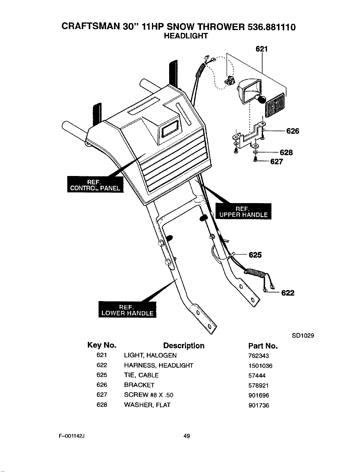
CRAFTSMAN 30" 11liP SNOW THROWER 536.881110
HEADLIGHT
621
$26
S28
627
622
Key No.
621
622
625
626
627
628
Description
LIGHT, HALOGEN
HARNESS, HEADLIGHT
TIE, CABLE
BRACKET
SCREW #8 X .5O
WASHER, FLAT
PaN No.
762343
1501036
57444
578921
901696
901736
SD1029
F-O01142J 49
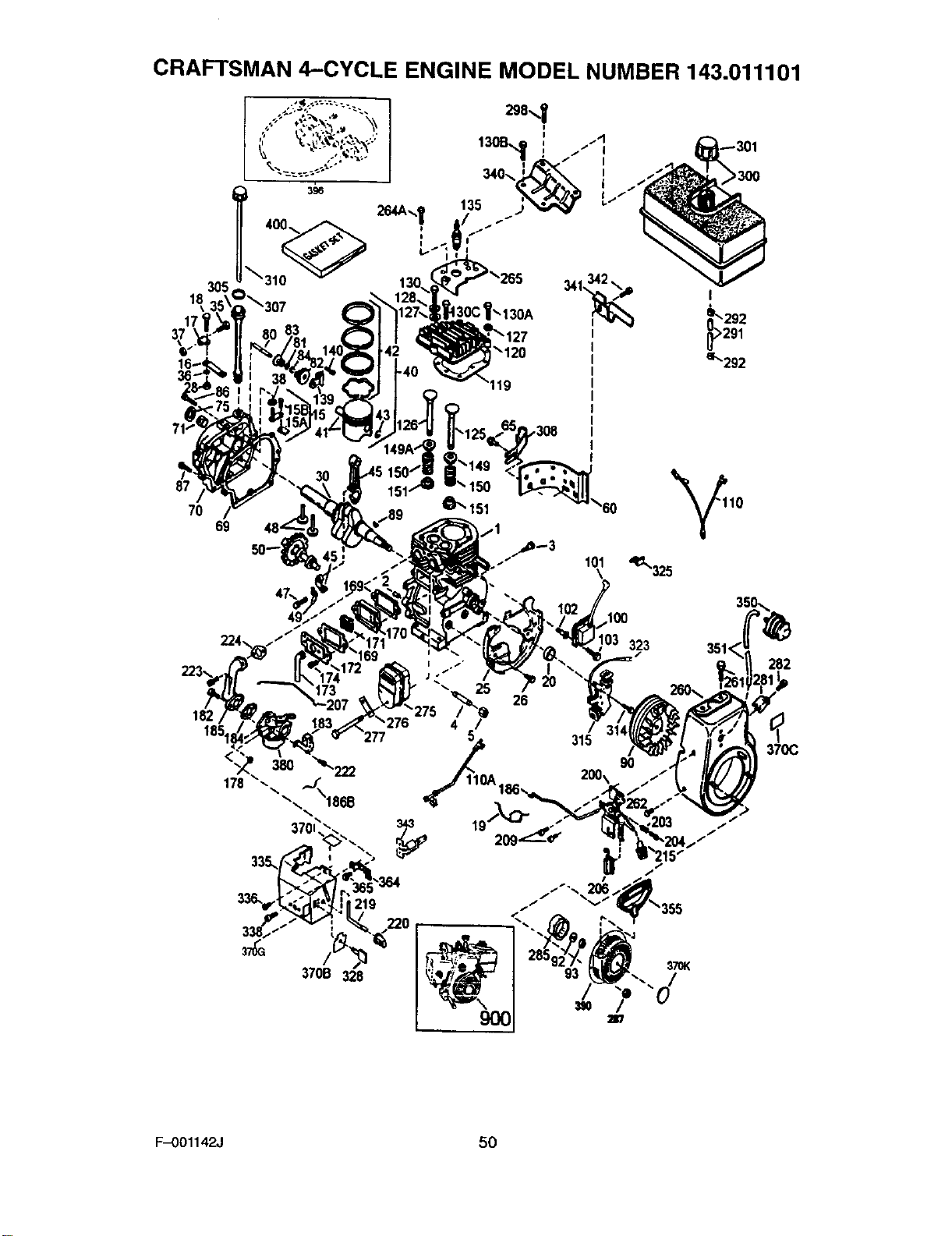
CRAFTSMAN 4-CYCLE ENGINE MODEL NUMBER 143.011101
7O 69
83
,308
224,
182
185
336,
370B 328
219
370K
F-O01142J 50

CRAFTSMAN 4-CYCLE ENGINE MODEL NUMBER 143.011101
KEY PART KEY PART
NO. NO. DESCRIPTION NO. NO. DESCRIPTION
1 35371 Cylinder Ass'y (2, 20, 72) 49 36896 Oil Dipper
2 27652 Dowel Pin 50 35375 Camshaft (MCR)
3 650820 Screw, 1/4-20xl/2" 60 33273A Blower Housing Extension
4 31857 Oil Drain Extension 65 650128 Screw, 10-24x1/2"
5 30969 Extension Cap 69 35262A Cylinder Cover Gasket
15 30669C Governor Rod 70 35376 Cylinder Cover
15A 30700 Governor yolk 71 35377 Crankshaft Bushing
15B 650494 Screw 6-40 x 5/16" 75 35319 Oil Seal
16 33454 Governor Lever 80 31845 Governor Shaft
17 29916 Governor Lever Clamp 81 30590A Washer
18 651018 Screw, Torx 7"-15 82 35378 Governor Gear Ass'y
19 34663 Speed Control Spring 83 30588A Governor Spool
20 35319 Oil Seal 84 29193 Retaining Ring
25 36460 g" Blower Hsg Baffle 86 650833 Screw, 1/4-20 x 1-3/16"
26 650561 Screw, 1/4-20 x 5/8" 87 650832 Screw, 1/4-20 x1-11/16"
28 30322 Locknut 8-32 89 32589 Flywheel Key
30 37231 Crankshaft 90 611193 Flywheel (W/Ring Gear)
35 29826 Screw, 10-32x3/4" 92 650880 Washer
36 29918 Lockwasher 93 650881 Flywheel Nut
37 29216 Locknut 10-32 100 35135 Solid State Ignition
38 29642 Retaining Ring 101 610118 Spark Plug Cover
40 35776A Piston, Pin & Ring Set 102 651024 Solid State Mounting Stud
(Std.) 103 651007 Screw, Torx 7-15
40 35777A Piston, Pin & Ring Set 110 35187 Ground Wire
(.010" OS) 110A 37047 Ground Wire
40 35778A Piston, Pin & Ring Set
(.020" OS) 119 36451 Cylinder Head Gasket
41 35773A Piston, Pin Ass'y. (Std.) 120 36449 Cylinder Head
41 35774A Piston, Pin Ass'y. 125 27878A Exhaust Valve (std)
(.010" OS) (Incl. 43) 125 27880A Exhaust Valve ( 1/32" OS)
41 35775A Piston, Pin Ass'y, 126 34035 Intake Valve (Std.)
(.020" OS) (Incl. 43) 126 34036 Intake Valve (1/32" OS)
42 35779 Ring Set (Std.) 127 650691 Washer
42 35780 Ring Set (.010" OS) 128 650690 Belleville Washer
42 35781 Ring Set (.020" OS) 129 650727 Screw, 5/16-18xl-3/4"
43 35772 Piston Pin Retaining Ring 130A 6021A Screw, 5/16-18 x 1-1/2"
45 36898 Connecting Rod Assy. 130B 651055 Screw, 5/16-18 x5/8"
47 651033 Connecting Rod Bolt 130C 650694A Screw, 5/16-18 x 2"
48 34034 Valve Lifter
F-OO1142J 51
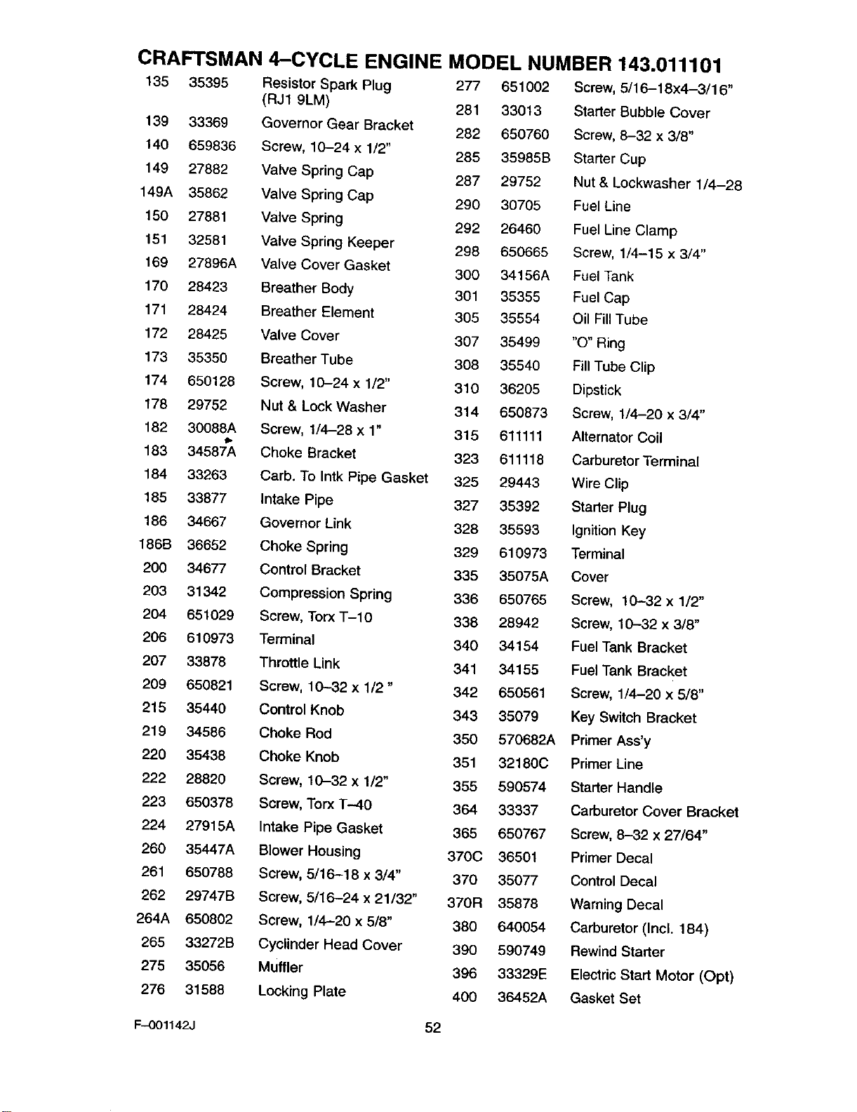
CRAFTSMAN 4-CYCLE ENGINE MODEL NUMBER 143.011101
135 35395 Resistor Spark Plug 277 651002 Screw, 5/16-18x4-3/16"
(RJ1 9LM) 281 33013 Starter Bubble Cover
139 33369 Governor Gear Bracket 282 650760 Screw, 8-32 x 3/8"
140 659836 Screw, 10-24 x 1/2" 285 35985B Starter Cup
149 27882 Valve Spring Cap 287 29752 Nut & Lockwasher 1/4-28
149A 35862 Valve Spring Cap 290 30705 Fuel Line
150 27881 Valve Spring 292 26460 Fuel Line Clamp
151 32581 Valve Spring Keeper 298 650665 Screw, 1/4-15 x 3/4"
169 27896A Valve Cover Gasket 300 34156A Fuel Tank
170 28423 Breather Body 301 35355 Fuel Cap
171 28424 Breather Element 305 35554 Oil Fill Tube
172 28425 Valve Cover 307 35499 "O" Ring
173 35350 Breather Tube 308 35540 Fill Tube Clip
174 650128 Screw, 10-24 x 1/2" 310 36205 Dipstick
178 29752 Nut & Lock Washer 314 650873 Screw, 1/4-20 x 3/4"
182 30088A Screw, 1/4-28 x 1" 315 611111 Alternator Coil
183 34587A Choke Bracket 323 611118 Carburetor Terminal
184 33263 Carb. To Intk Pipe Gasket 325 29443 Wire Clip
185 33877 Intake Pipe 327 35392 Starter Plug
166 34667 Governor Link 328 35593 Ignition Key
186B 36652 Choke Spring 329 610973 Terminal
200 34677 Control Bracket 335 35075A Cover
203 31342 Compression Spring 336 650765 Screw, 10--32 x 1/2"
204 651029 Screw, Torx T-IO 336 28942 Screw, 10--32 x 3/8"
206 610973 Terminal 340 34154 Fuel Tank Bracket
207 33878 Throttle Link 341 34155 Fuel Tank Bracket
209 650821 Screw, 10-32 x 1/2" 342 650561 Screw, 1/4-20 x 5/8"
215 35440 Control Knob 343 35079 Key Switch Bracket
219 34586 Choke Rod 350 570682A Primer Ass'y
220 35438 Choke Knob 351 32180C Primer Line
222 28820 Screw, 10-32 x 1/2" 355 590574 Starter Handle
223 650378 Screw, Torx T-40 364 33337 Carburetor Cover Bracket
224 27915A Intake Pipe Gasket 365 650767 Screw, 8-32 x27/64"
260 35447A Blower Housing 370C 36501 Primer Decal
261 650788 Screw, 5/16-18 x 3/4" 370 35077 Control Decal
262 29747B Screw, 5/16-24 x 21/32" 370R 35878 Warning Decal
264A 650802 Screw, 1/4-20 x 5/8" 380 640054 Carburetor (Incl. 184)
265 33272B Cyclinder Head Cover 390 590749 Rewind Starter
275 35056 Muffler 396 33329E Electric Start Motor (Opt)
276 31588 Locking Plate 400 36452A Gasket Set
F-O01142J 52
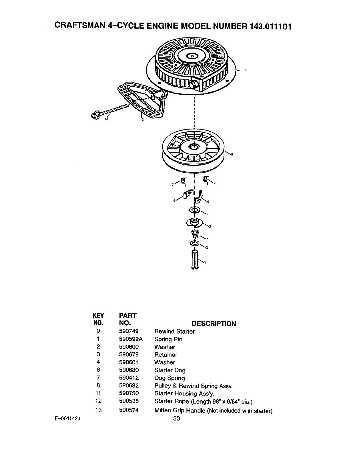
CRAFTSMAN 4-CYCLE ENGINE MODEL NUMBER 143.011101
12 13
I
F-.OO1142J
KEY
NO,
0
1
2
3
4
6
7
8
11
12
13
PART
NO.
590749
590599A
590600
590679
590601
590680
590412
590682
590750
590535
590574
DESCRIPTION
Rewind Starter
Spring Pin
Washer
Retainer
Washer
Starter Dog
Dog Spring
Pulley & Rewind Spring Assy,
Starter Housing Ass'y.
Starter Rope (Length 98" x 9/64" dia.)
Mitten Grip Handle (Not included with starter)
53
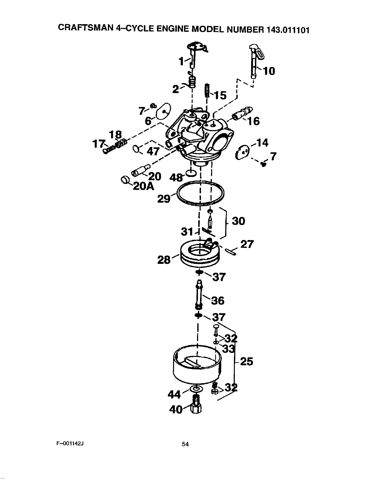
CRAFTSMAN 4-CYCLE ENGINE MODEL NUMBER 143.011101
27
_37
36
-25
F-OOl142J 54
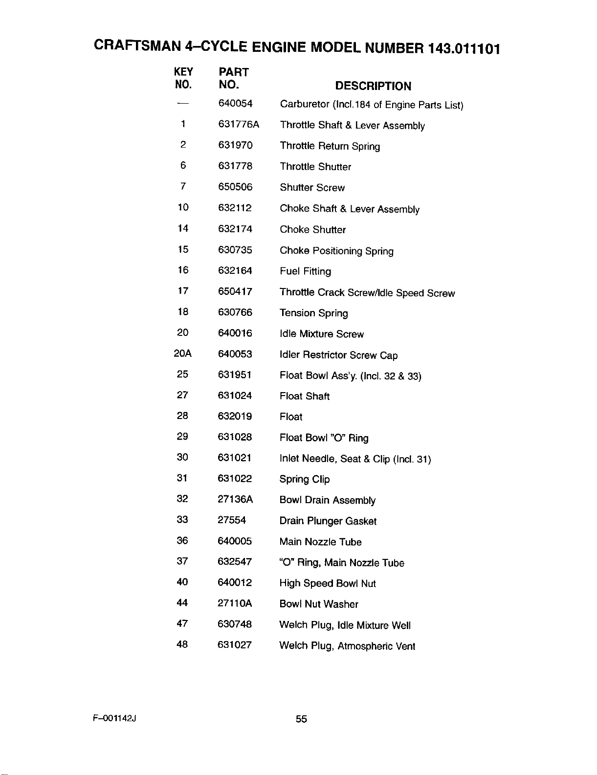
CRAFTSMAN 4-CYCLE ENGINE MODEL NUMBER 143.011101
KEY PART
NO. NO.
-- 640054
1 631776A
2 631970
6 631778
7 650506
10 632112
14 632174
15 630735
16 632164
17 650417
18 630766
20 640016
20A 640053
25 631951
27 631024
28 632019
29 631028
30 631021
31 631022
32 27136A
33 27554
36 640005
37 632547
40 640012
44 27110A
47 630748
48 631027
DESCRIPTION
Carburetor (Incl.184 of Engine Parts List)
Throttle Shaft & Lever Assembly
Throttle Return Spring
Throttle Shutter
Shutter Screw
Choke Shaft & Lever Assembly
Choke Shutter
Choke Positioning Spring
Fuel Fitting
Throttle Crack Screw/Idle Speed Screw
Tension Spring
Idle Mixture Screw
Idler Restrictor Screw Cap
Float Bowl Ass'y. (Incl. 32 & 33)
Float Shaft
Float
Float Bowl "O" Ring
Inlet Needle, Seat & Clip (Incl. 31)
Spring Clip
Bowl Drain Assembly
Drain Plunger Gasket
Main Nozzle Tube
"O" Ring, Main Nozzle Tube
High Speed Bowl Nut
Bowl Nut Washer
Welch Plug, Idle Mixture Well
Welch Plug, Atmospheric Vent
F-001142J 55
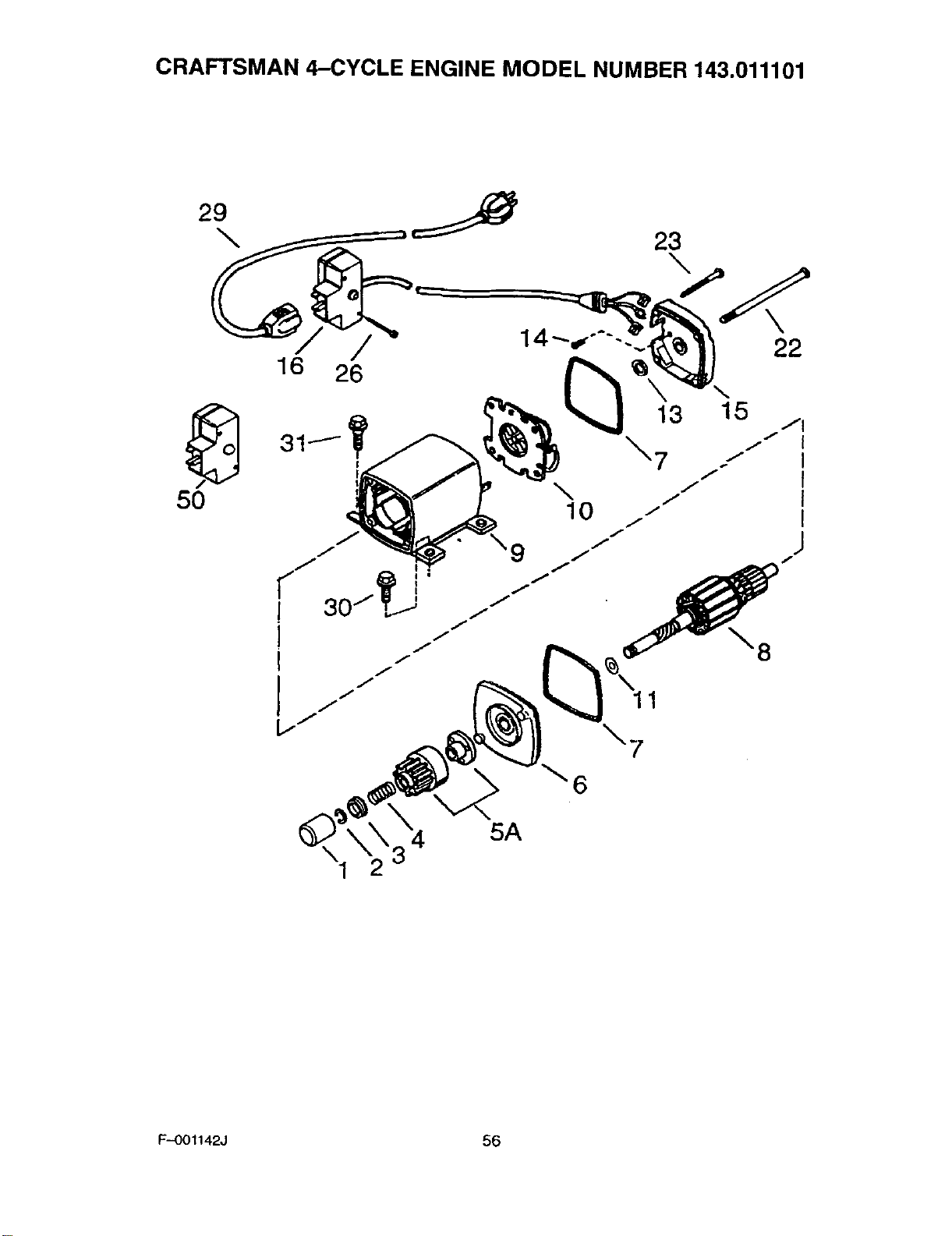
CRAFTSMAN 4-CYCLE ENGINE MODEL NUMBER 143.011101
29 J
\
/
16 26 14----4"'--...,
23
\22
50 \10
5A
12
F,-OOl142J 56
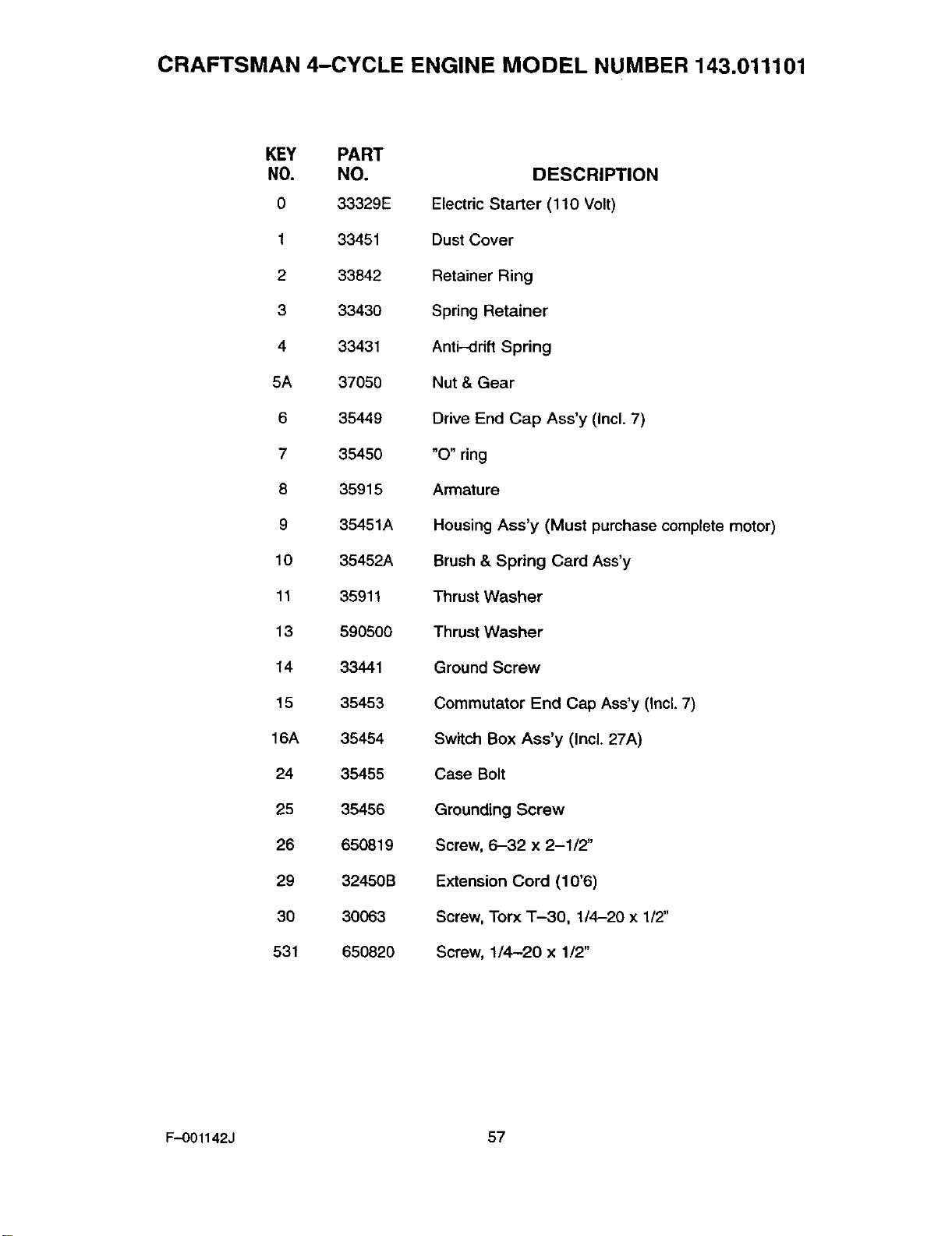
CRAFTSMAN 4-CYCLE ENGINE MODEL NUMBER 143.011101
KEY PART
NO. NO.
033329E
133451
2 33842
3 33430
4 33431
5A 37050
6 35449
7 35450
8 35915
9 35451A
10 35452A
11 35911
13 590500
14 33441
15 35453
16A 35454
24 35455
25 35456
26 650819
29 32450B
30 30063
531 650820
DESCRIPTION
Electric Starter (110 Volt)
Dust Cover
Retainer Ring
Spring Retainer
Anti-drift Spring
Nut & Gear
Drive End Cap Ass'y (Incl. 7)
"O" ring
Armature
Housing Aes'y (Must purchase complete motor)
Brush & Spring Card Ass'y
Thrust Washer
Thrust Washer
Ground Screw
Commutator End Cap Ass'y (Incl. 7)
Switch Box Ass'y (Incl. 27A)
Case Bolt
Grounding Screw
Screw, 6-32 x 2-1/2"
Extension Cord (10'6)
Screw, Torx T-30, 1/4-20 x 1/2"
Screw, 1/4-20 x 1/2"
F-001142J 57

NOTES
F-OOl142J 58

NOTES
F-OO1142J 59
For the repair or replacement parts you
need delivered directly to your home
Call 7am-7pm, 7days a week
1-800-366-PART
(1-800-366-7278)
Para ordenar piezas con entrega
a domicilio - 1-800-659-7084
For in-house major brand repair service
Call 24 hours a day, 7days a week
1-800-4-REPAIR
(1-800--473-7247)
Para pedir servicio de reparaci6n a
domicilio- 1-800-676-5811
For the location of a Sears Parts and
Repair Center in your area
Call 24 hours a day, 7days a week
1-800-488-1222 mmmmmm
mmmmmm
For information on purchasing a Sears
Maintenance agreement or to inquire
about an existing Agreement
Call 9am-5pm, Monday-Saturday
1-800-827-6655
When requesting service or ordering
parts, always provide the following infor-
mation:
•Product Type •Part Number
•Model Number • Part Description
8BAR8
• _ _ir_o_l_ Printed in U.S.A.