Page 1
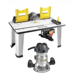
Router Table
241-1462
For questions / comments, technical assistance or repair parts –
Please Call Toll Free: 1-866-858-2664. (M-F 8:30am – 5:00pm EST)
OPERATOR’S MANUAL
CAUTION:
To Reduce The Risk Of Injury, User Must Read And
Understand The Operator’s Manual. Save These Instructions For
Future Reference.

TABLE OF CONTENTS
Safety Symbols ......................................................... Page 2
Safety Instructions ...................................................... Page 3
Overview/Specications ................................................. Page 8
Assembly ............................................................. Page 9
Operation ............................................................ Page 17
Maintenance .......................................................... Page 22
Troubleshooting ....................................................... Page 22
Warranty ............................................................. Page 26
Page 2
SAFETY SYMBOLS
Some of these following symbols may be used on this tool. Please study them and learn their
meaning. Proper interpretation of these symbols will allow you to operate the tool better and
more safely.
WARNING:
To ensure safety and reliability, all repairs should be performed by a
qualied service technician.
Symbol
Name
Designation / Explanation
V Volts Voltage
A Amperes Current
Hz Hertz Frequency (cycles per second)
W Watts Power
∿
Alternating current Type of current
�
Direct current Type or characteristic of current
n
o
No-load speed Rotational speed at no load
Class II construction Double insulated construction
.../min
Per minute
Revolutions, strokes, surface speed
orbits, etc., per minute
Wear safety goggles
WARNING:
The operation of any
power tool can result in foreign objects
being thrown into your eyes, which can
result in severe eye damage. Before
beginning power tool operation, always
wear safety goggles or safety glasses
with side shields and a full-face shield
when needed. We recommend a Wide
Vision Safety Mask for use over eye-
glasses or standard safety glasses with
side shields. Always use eye protection
which is marked to comply with
ANSI Z87.1.

The purpose of safety symbols is to attract your attention to possible dangers. The
safety symbols and the explanations with them deserve your careful attention and
understanding. The symbol warnings do not, by themselves, eliminate any danger. The
instructions and warnings they give are no substitutes for proper accident prevention
measures.
WARNING:
Be sure to read and understand all safety instructions in this manual,
including all safety alert symbols such as “DANGER,” ”WARNING,” and “CAUTION”
before using this tool. Failure to follow all instructions listed below may result in
electric shock, re, and/or serious personal injury.
SYMBOL MEANING
SAFETY ALERT SYMBOL: Indicates DANGER, WARNING, OR CAUTION.
May be used in conjunction with other symbols or pictographs.
Indicates an imminently hazardous situation, which, if not avoided,
will result in death or serious injury.
Indicates a potentially hazardous situation, which, if not avoided,
could result in death or serious injury.
Indicates a potentially hazardous situation, which, if not avoided,
could result in minor or moderate injury.
NOTICE:
Equipment and/or property damage may result if these instructions are not
followed.
SAVE THESE INSTRUCTIONS!
WARNING:
Page 3
SAFETY INSTRUCTIONS
DANGER:
CAUTION:

Page 4
SAFETY INSTRUCTIONS
KNOW THE TOOL
WARNING:
To reduce the risk
of injury, user must read the Operator’s
Manual.
Read this Instruction Manual and all of
the labels afxed to the router table care-
fully before operating this tool. Keep this
manual available for future reference.
IMPORTANT
This tool should only be serviced by a
qualied service technician.
GROUNDING INSTRUCTIONS
1. In the event of a malfunction or
breakdown, grounding provides a path
of least resistance for electric current to
reduce the risk of electric shock. This tool
is equipped with an electric cord having
an equipment grounding conductor and a
grounding plug. The plug must be plugged
into a matching outlet that is properly
installed and grounded in accordance with
all local codes and ordinances.
2. Do not modify the plug provided – if it will
not t the outlet, have the proper outlet
installed by a qualied electrician.
3. Improper connection of the equipment-
grounding conductor can result in a risk
of electric shock. The conductor with
insulation having an outer surface that is
green with or without yellow stripes is the
equipment-grounding conductor. If repair or
replacement of the electric cord or plug is
necessary, do not connect the equipment-
grounding conductor to a live terminal.
4. Check with a qualied electrician
or service personnel if the grounding
instructions are not completely under-
stood, or if in doubt as to whether the
tool is properly grounded.
5. Use only 3-wire extension cords
that have 3-prong grounding plugs
and 3-pole receptacles that accept the
tool’s plug.
6. Repair or replace damaged or worn
cord immediately.
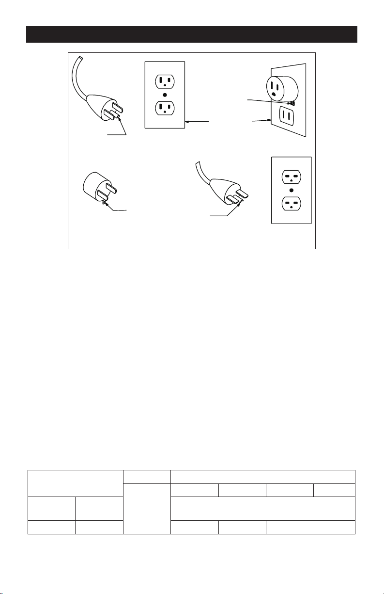
7. This tool is intended for use on a
circuit that has an outlet that looks like
the one illustrated in Sketch A in the
gure below. The tool has a grounding
plug that looks like the plug illustrated
in Sketch A in the gure below. A
temporary adapter, which looks like the
adapter illustrated in Sketches B and C,
may be used to connect this plug to a
2-pole receptacle as shown in Sketch B
if a properly grounded outlet is not
available. The temporary adapter should
be used only until a properly grounded
outlet can be installed by a qualied
electrician. The green-colored rigid
ear, lug, and the like, extending from
the adapter must be connected to a
permanent ground such as a properly
grounded outlet box.
Page 5
8. Keep guards in place and in working
order.
9. Remove adjusting keys and wrenches.
Form the habit of checking to see that keys
and adjusting wrenches are removed from
the tool before turning it on.
10. Keep the work area clean. Cluttered
areas and benches invite accidents.
11. Don’t use in dangerous environments.
Don’t use power tools in damp or wet
locations, or expose them to rain. Keep the
work area well lighted.
12. Keep children away. All visitors should
be kept safe distance from the work area.
13. Make the workshop child proof with
padlocks, master switches, or by removing
starter keys.
14. Don’t force the tool. It will do the job
better and more safely at the rate for which
it was designed.
15. Use the right tool. Don’t force a tool
or attachment to do a job for which it was
not designed.
16. Use a proper extension cord.
Make sure your extension cord is in good
condition. When using an extension cord, be
sure to use one heavy enough to carry the current
your product will draw. An undersized cord will
cause a drop in line voltage, resulting in loss
of power and overheating. Table 1 shows the
correct size to use, depending on cord length
and nameplate ampere rating. If in doubt, use
the next heavier gage. The smaller the gage
number, the heavier the cord.
Ampere Rating
Volts Total length of cord in feet
120V
25 ft 50ft 100ft 150ft
More Than
Not More
Than
AWG
12 16 14 12 Not Recommended
Table 1: Minimum gage for cord
SAFETY INSTRUCTIONS
Grounding
Pin
Grounding
Pin
Adapter
Metal Screw
Cover of Grounded
Outlet Box
Grounding
Means
AA210
(C)
(D)
(B)
(A)

Page 6
SAFETY INSTRUCTIONS
17. Wear proper apparel. Do not wear
loose clothing, gloves, neckties, rings,
bracelets, or other jewelry which may get
caught in moving parts. Nonslip footwear is
recommended. Wear protective hair cover-
ing to contain long hair.
18. Always use safety glasses. Also use
a face or dust mask if the cutting operation is
dusty. Everyday eyeglasses only have impact
resistant lenses; they are NOT safety glasses.
19. Secure your work. Use clamps or a vise
to hold work whenever practical. It’s safer
than using your hand and it frees both hands
to operate the tool.
20. Don’t overreach. Keep proper footing
and balance at all times.
21. Maintain tools with care. Keep
tools sharp and clean for best and safest
performance. Follow instructions for
lubricating and changing accessories.
22. Disconnect tools before servicing
and when changing accessories, such as
blades, bits, cutters, and the like.
23. Reduce the risk of unintentional
starting. Make sure that the switch is in the
off position before plugging in.
24. Use recommended accessories.
Consult the owner’s manual for
recommended accessories. The use of
improper accessories may cause a risk of
injury to persons.
25. Never stand on the tool. Serious inju-
ry could occur if the tool is tipped or if the
cutting tool is unintentionally contacted.
26. Check damaged parts. Before further
use of the tool, a guard or other part that
is damaged should be carefully checked
to determine that it will operate properly
and perform its intended function – check
for alignment of moving parts, binding
of moving parts, breakage of parts,
mounting, and any other conditions that
may affect its operation. A guard or other
part that is damaged should be properly
repaired or replaced.
27. Direction of feed: Feed work into a
blade or cutter only against the direction of
rotation of the blade or cutter.
28. Never leave a tool running unattended.
TURN THE POWER OFF. Don’t leave the tool
until it comes to a complete stop.
SPECIFIC SAFETY RULES FOR
ROUTER TABLES
1. Read and understand all instructions
and warnings in the Instruction Manual
for the router table and the router
used with this table. Failure to follow all
instructions and warnings may result in
serious personal injury.
2. Fully assemble and tighten all fasteners
required for this table and for mounting the
router to the table. Do not use the router
table until all assembly and installation
steps have been completed.
3. Before each use, check the router and
the table to ensure that all fasteners are
still tight. A loose table is unstable, and may
shift during use.
4. Unplug the router before installing it
into the table.
5. Turn off the router-table safety switch
that controls power to the router or
unplug the router before making adjustments
or changing accessories, such as bits
or cutters.
6. Always wear a dust mask and ear
protection when using this power tool.
7. Only use cutters that are designed for
the particular router in use.
8. Only use sharp cutters that are not
chipped or cracked. Blunt cutters will
cause stalling.
9. Secure small pieces of wood rmly
before working. Never hold a workpiece by
hand.
10. Secure the workpiece using clamping
equipment.
11. Before starting the router, check that
the cutter bit is rmly positioned and
secured in the collet.
12. Do not exceed the maximum indicated
rotation speed of the cutter bit.

Page 7
13. Routing operations must always be
performed against the direction of rotation
of the cutter bit (cutter rotation).
14. Note that the direction of rotation is
reversed when the router is installed in the
router table: when installed in the router ta-
ble, the cutter rotates counter-clockwise.
15. The cutter bit must be running at full
speed before it is lowered to the work-
piece.
16. Be prepared for the reaction torque
of the router, particularly if the cutter bit
becomes jammed in the workpiece.
17. Become familiar with the working
area, and be alert for possible hazards that
cannot be heard due to the noise of the
router.
18. Never slow the router down with your
hands.
19. Do not touch the cutter immediately
after operation. It may be extremely hot,
and could burn.
20. Never stop the router by applying
lateral pressure to the cutter.
21. Do not force the router. It will do a
better job if it is allowed to work at its
intended speed.
22. Avoid cutting nails and screws.
Inspect timber before cutting, and remove
all nails and screws.
23. In the event of an electrical or
mechanical malfunction, switch the router
off immediately, and disconnect the power
cord from the outlet.
24. Wear eye protection. Feed work piece
against rotation of cutter. Do not use
awkward hand positions. Keep ngers
away from revolving-use xtures when
necessary. Use overhead guard when
adjustable fence is not in place. Do not
expose to rain or use in damp locations.
Risk of re or electric shock. Do not exceed
15A max load for receptacles. Risk of re
or injury. For use with router 241-0974 and
241-0836, 241-1462, 241-1463, 241-1464.
SAFETY INSTRUCTIONS
Page 8
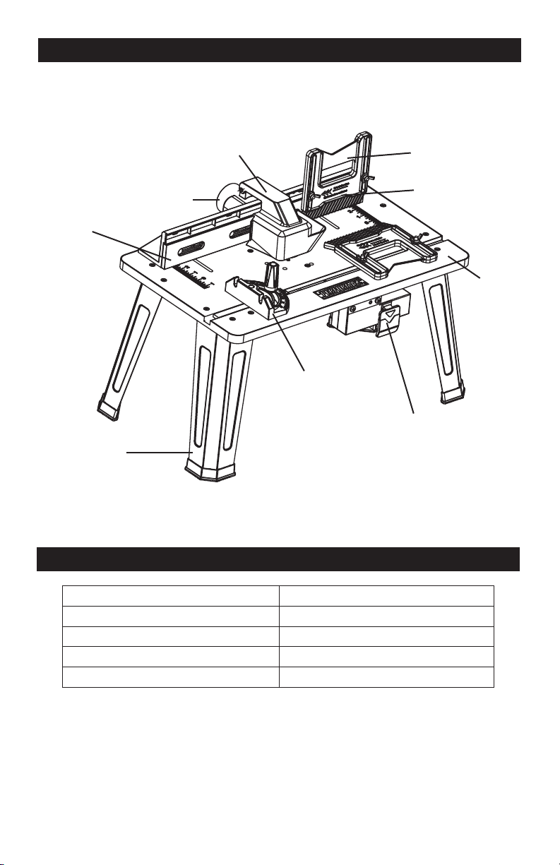
OVERVIEW
SPECIFICATIONS
Table Size 14 1/8” x 23 1/2”
Table Height 12 1/2”
Switch Rating 120V 60Hz 15A
Cord Length 8’
Weight (Router table only) 13lbs. 14oz. (6.3kg)
Vacuum adaptor
Dust collection and guard
Miter gauge
Out-feed fence
Leg
Integrated safety switch
Tabletop
In-feed fence
Feather board
Page 9
ASSEMBLY
WARNING:
If any part is broken or
missing, DO NOT attempt to plug in the
power cord, attach the battery, or operate
the tool until the broken or missing part is
replaced. Failure to do so could result in
possible serious injury.
WARNING:
Do not attempt to
modify this tool or create accessories not
recommended for use with this tool. Any
such alteration or modication is misuse
and could result in a hazardous condition
leading to possible serious injury.
WARNING:
Your tool should never
be connected to the power source when
you are assembling parts, making
adjustments, installing or removing
application tools, cleaning, or when it is
not in use. Disconnecting the tool will
prevent accidental starting, which could
cause serious personal injury.
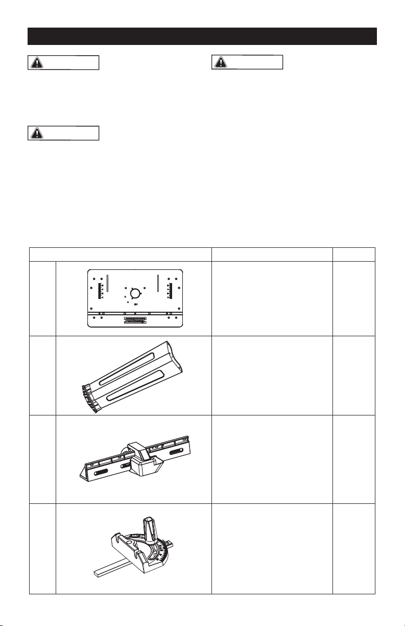
CONTENTS
Key No Description Quantity
1 Router table 1
2 Table leg 4
3 Fence assembly 1
4 Miter gauge assembly 1
Page 10
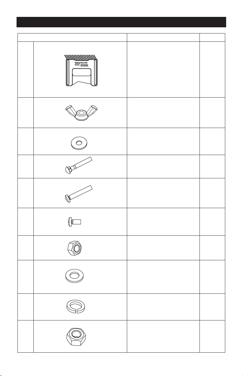
Key No Description Quantity
5 Feather board 2
6 Wing nut M6 6
7
Plain washer Φ6
6
8
Long round-head
square-neck bolt M6x40
6
9 Long pan-head screw M5x25 12
10 Short pan-head screw M6x12 2
11 Small nut M5 12
12
Small washer Φ5
12
13
Spring washer Φ5
12
14 Large nut M6 2
ASSEMBLY
Page 11
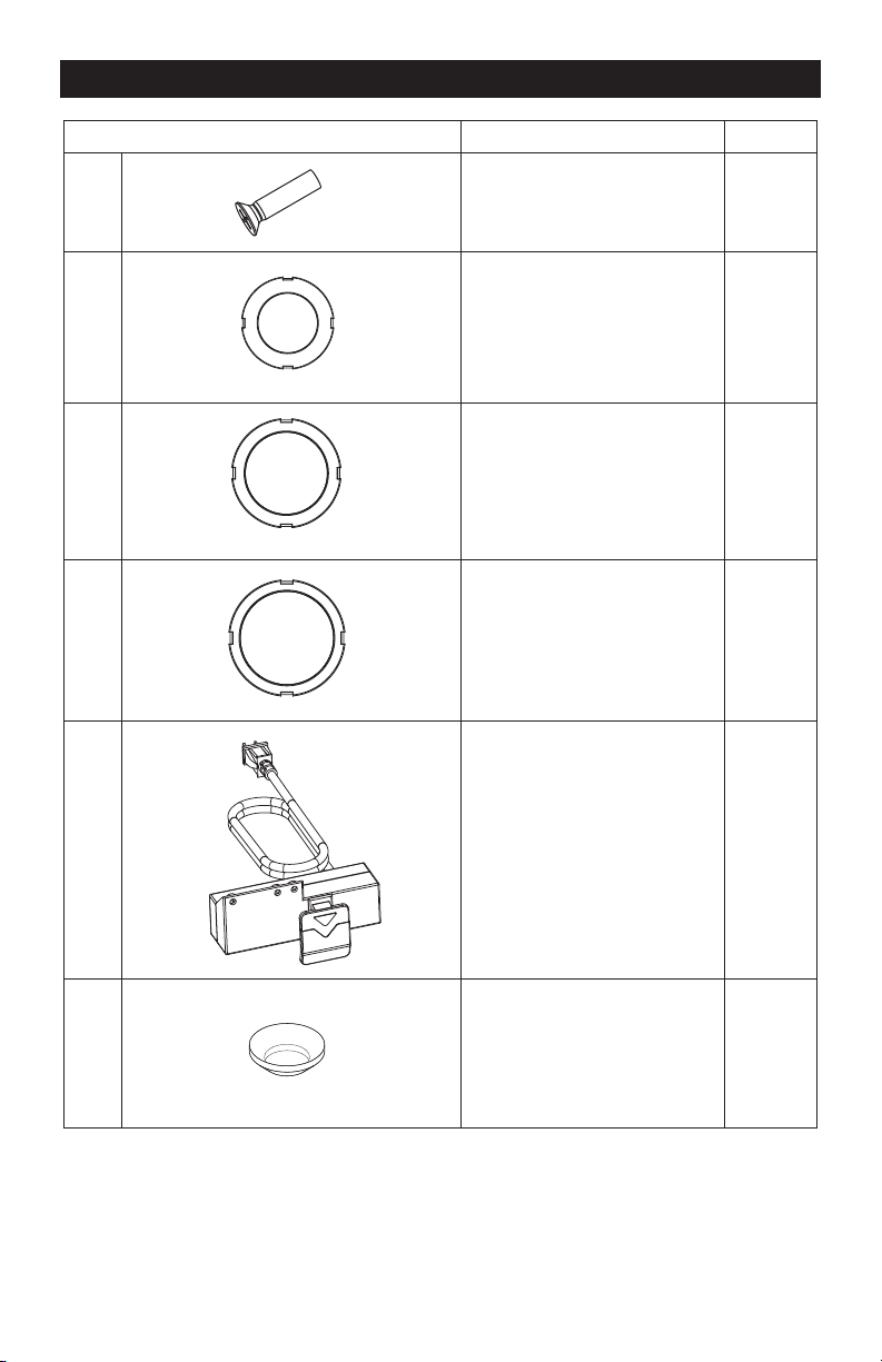
Key No Description Quantity
15 Flat-head screw M5x20 3
16 Insert ring with 1 1/4” 1
17 Insert ring with 1 1/2” 1
18 Insert ring with 1 3/4” 1
19 Switch box 1
20
Saddle washer Φ5
3
ASSEMBLY
Page 12
ASSEMBLY
UNPACKING
1. Carefully remove the tool and any
accessories from the box. Make sure
that all items listed in the packing list are
included.
2. Inspect the tool carefully to make sure
that no breakage or damage occurred
during shipping.
3. Do not discard the packing material
until you have carefully inspected and
satisfactorily operated the tool.
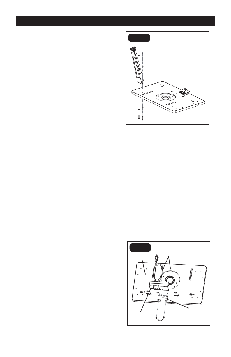
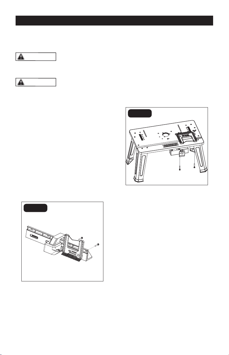
ATTACHING THE LEGS TO THE
TABLETOP (FIG. 1)
1. Place the tabletop on a at, level
surface, with the underside of the table
facing up.
2. Position one corner of the table so that
it extends beyond the edge of the work
surface far enough to gain access to the
three holes in that corner of the router
table.
3. Align the three holes on the tabletop with
the holes in the leg bracket.
4. Place a small washer (12) onto each of
three long pan-head screws (9). Insert
the long pan-head screws up through
the holes in the table and through the
holes in the leg bracket. Place a spring
washer (13), and a small nut (11) (in
the order listed) on the threads of each
screw. Loosely tighten the nuts (Fig. 1).
5. Repeat with the other three legs.
FIG. 1
ATTACH THE SWITCH BOX TO
THE TABLE TOP (FIG. 2)
1. Place the tabletop on a at, level
surface, with the underside of the table
facing up.
2. Position the switch box against the
support.
3. Align the two holes in the support with
the holes in the switch box, as shown
in Fig. 2.
4. Insert the short pan-head screws (10)
through the two holes in support and
switch box. Place a large nut (14) on
each screw.
5. Securely tighten the two nuts.
FIG. 2
Tabletop
Switch box
Nuts
Support
Screws
Page 13
FIG. 3
FIG. 4
ASSEMBLY
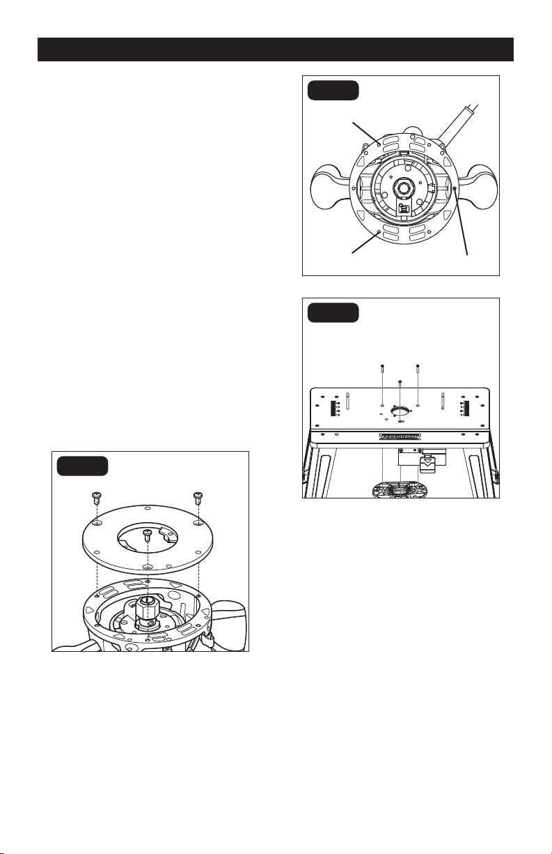
ATTACHING THE ROUTER TO
THE TABLE
Attach the router to the router table after you
have assembled the table.
1. Unplug the router and the router table.
2. Loosen the three screws to remove
the plastic sub-base from the router
base (Fig. 3).
3. Position the router upside down, and
align the three holes in the center of the
router table with the holes (Fig. 4) in the
router, as shown in Fig. 5.
4. Insert a at-head screw (15) through
each of the three router-table hole into
the router holes.
5. Hold the router with one hand, and
securely tighten each at-head screw
(15) with Philips screwdriver (available
separately) by the other hand.
NOTICE:
Select and assemble the
correct router bit before attaching with
router table.
FIG. 5
Mounting hole
Mounting hole
Mounting hole
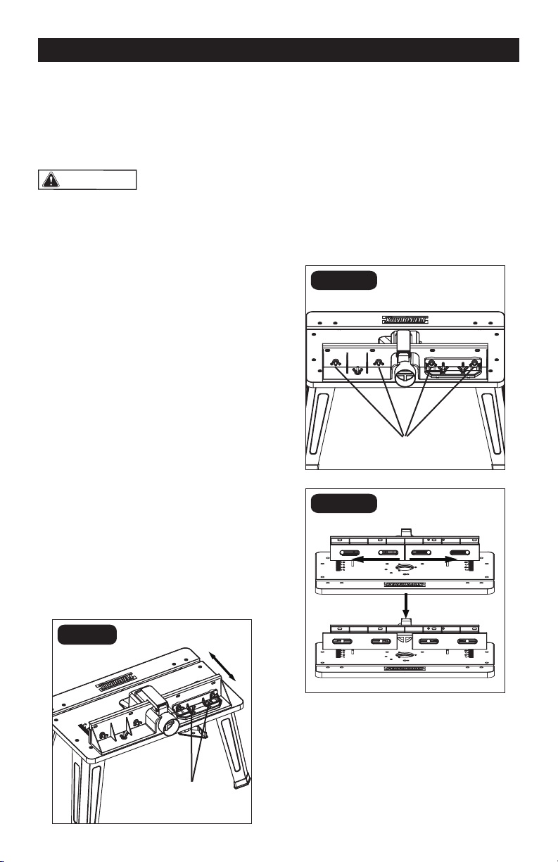
Page 14
ATTACHING THE FENCE
ASSEMBLY TO THE TABLE (FIG. 6)
WARNING:
Always unplug the
router before attaching or removing the
fence. The fence is shipped completely
assembled.
1. Place the fence assembly on the
tabletop surface, and align the two
holes on the bottom of the fence
assembly with the two slots on the router
table.
2. From underneath, slide a long
round-head square-neck bolt (8) through
the left hole and another long round-head
square-neck bolt (8) through the right
hole. Slide a plain washer (7) onto each
bolt.
3. Put the wing nuts (6) on the bolts.
Secure the fence to the tabletop surface
by tightening the wing nuts.
4. To prepare the table for transportation
and storage, loosen the clamping knobs
and remove the fence from the table.
WARNING:
Always attach the
fence to the table when you use the router
table.
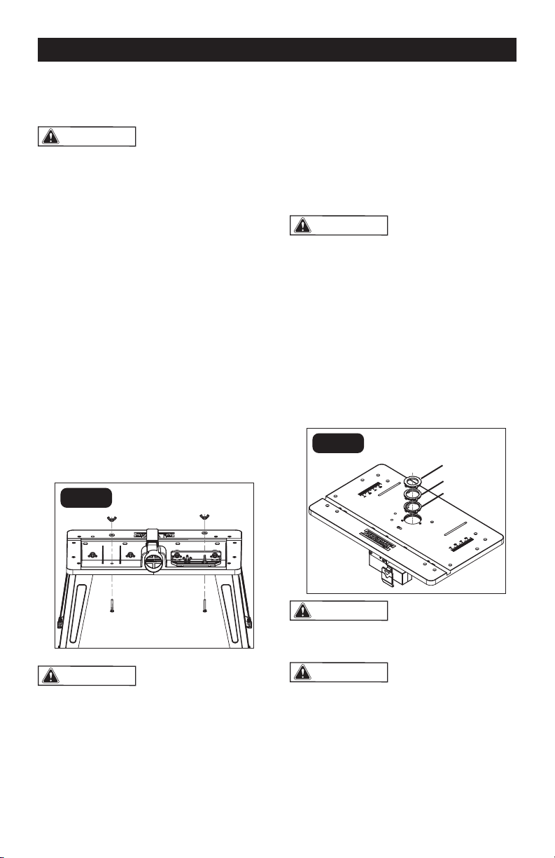
ATTACHING THE TABLETOP
INSERT RINGS (FIG. 7)
This router table includes three tabletop
inserts, each with openings of a different
diameter: insert with 1 1/4” Diameter Hole
(16), insert with 1 1/2” Diameter Hole (17),
insert with 1 3/4” Diameter Hole (18).
WARNING:
Always unplug the
router before attaching or removing the
insert rings.
1. Position the tabletop insert over the
insert opening in the router table.
2. Press the insert into the insert opening in
the router table.
3. Press down evenly over the tabs until the
insert locks in place.
4. To remove, pull up gently until the tabs
disengage. When not in use, store
tabletop inserts in a convenient place.
WARNING:
DO NOT attempt to
remove tabletop inserts from the insert
opening unless the router is unplugged.
WARNING:
DO NOT use bits that
have a cutting diameter that exceeds the
clearance hole in the table inserts. Select
a table insert that has a clearance hole
1/12”(2mm) larger than the diameter of the
bit being used.
FIG. 6
FIG. 7
ASSEMBLY
1 1/4”
1 1/2”
1 3/4”
Page 15
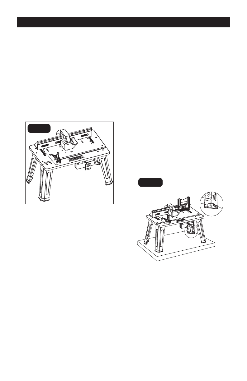
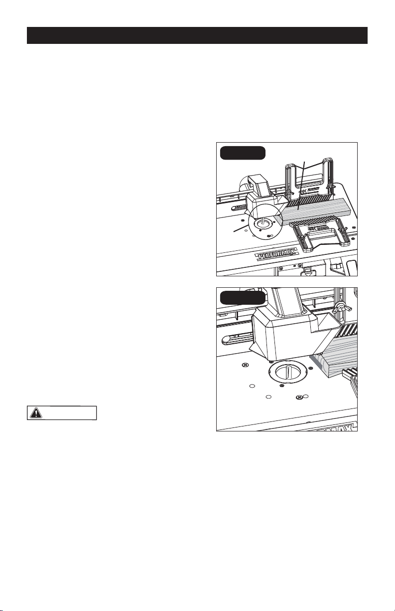
ATTACHING THE MITER
GAUGE (FIG. 8)
1. The miter gauge is shipped completely
assembled.
2. Attach the miter gauge to the table by
placing the miter gauge bar in the slot on
the table.
3. To adjust the miter gauge, loosen the
miter gauge knob, rotate the miter gauge
to the desired angle and tighten the knob
again.
ASSEMBLY
FIG. 8
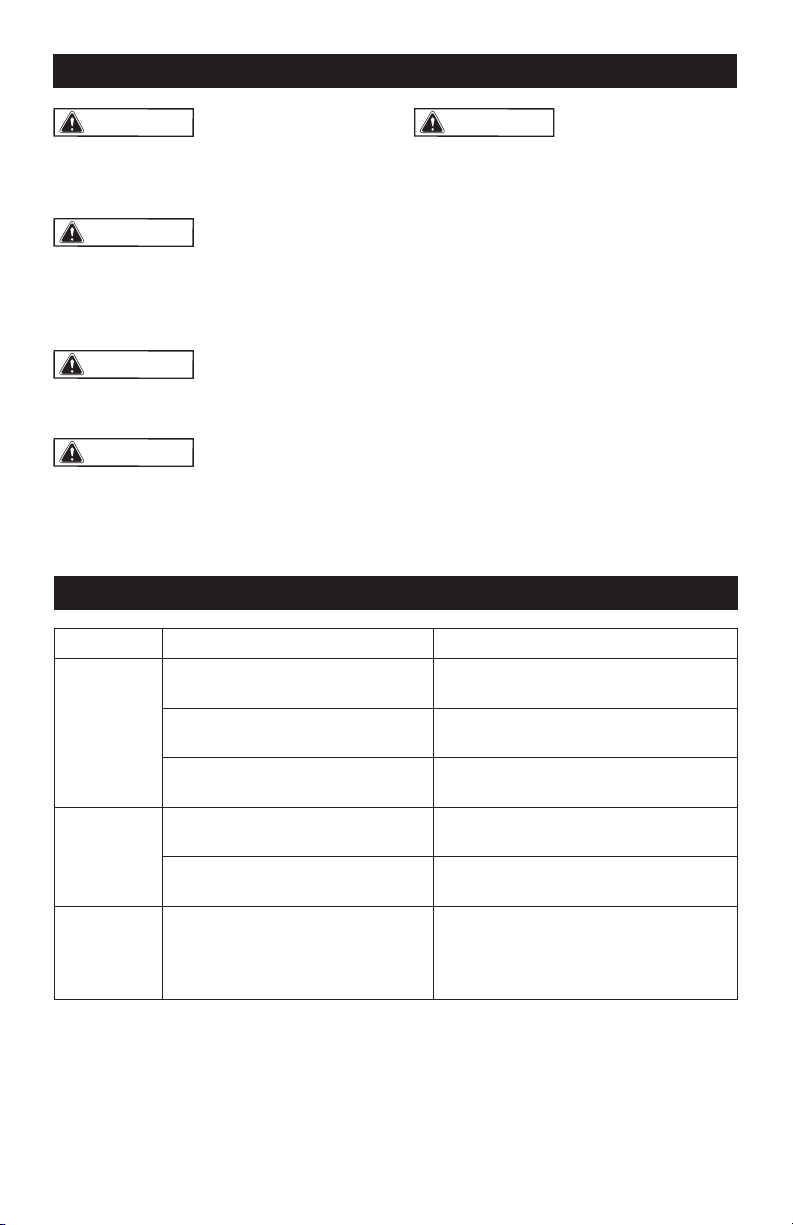
FIG. 9
MOUNTING THE TABLE TO A
WORK SURFACE (FIG. 9)
1. Place the router table upright on a
sturdy surface, such as a work stand,
workbench, or countertop.
2. While holding the router table in place,
mark the location of the mounting hole
(13/32” [10mm] diam.) in each of the legs
on the work surface.
3. Remove the router table.
4. Drill a hole into the work surface at each
of the marked locations.
5. Place the router table on the work
surface and align the holes in the table
legs with the holes in the work surface.
6. Secure the router table to the work
surface with four bolts and nuts (not
included).
7. Tighten the bolts securely.
Page 16
ATTACHING THE FEATHER
BOARDS (FIG. 10, 11)
WARNING:
Always unplug the
router before attaching or removing the
feather boards.
WARNING:
The front and back
side of each feather board is marked to
indicate proper feed direction. The
direction of the arrow marked on the
feather board must be consistent with
the in-feed direction.
ATTACH THE FEATHER BOARD
TO THE FENCE
1. Place the feather board on the fence as
shown in Fig. 10.
2. Insert the long round-head square-neck
bolt (8) through the holes in the fence
and the slot in the feather boards.
3. Slide a plain washer (7) onto the bolt.
4. Tighten the wing nut (6) to secure the
fence and feather board.
ASSEMBLY
FIG. 10
FIG. 11
ATTACH THE FEATHER BOARD
TO THE TABLETOP SURFACE
1. Place the feather board on the tabletop
surface.
2. Insert the long round-head square-neck
bolt (8) through the holes in the tabletop
slot and the slot in the feather boards.
3. Slide a plain washer (7) onto the bolt.
4. Tighten the wing nut (6) to secure the
fence and feather board.
Page 17
Dust Shield
FIG. 12
FIG. 13
FIG. 14
FIG. 15
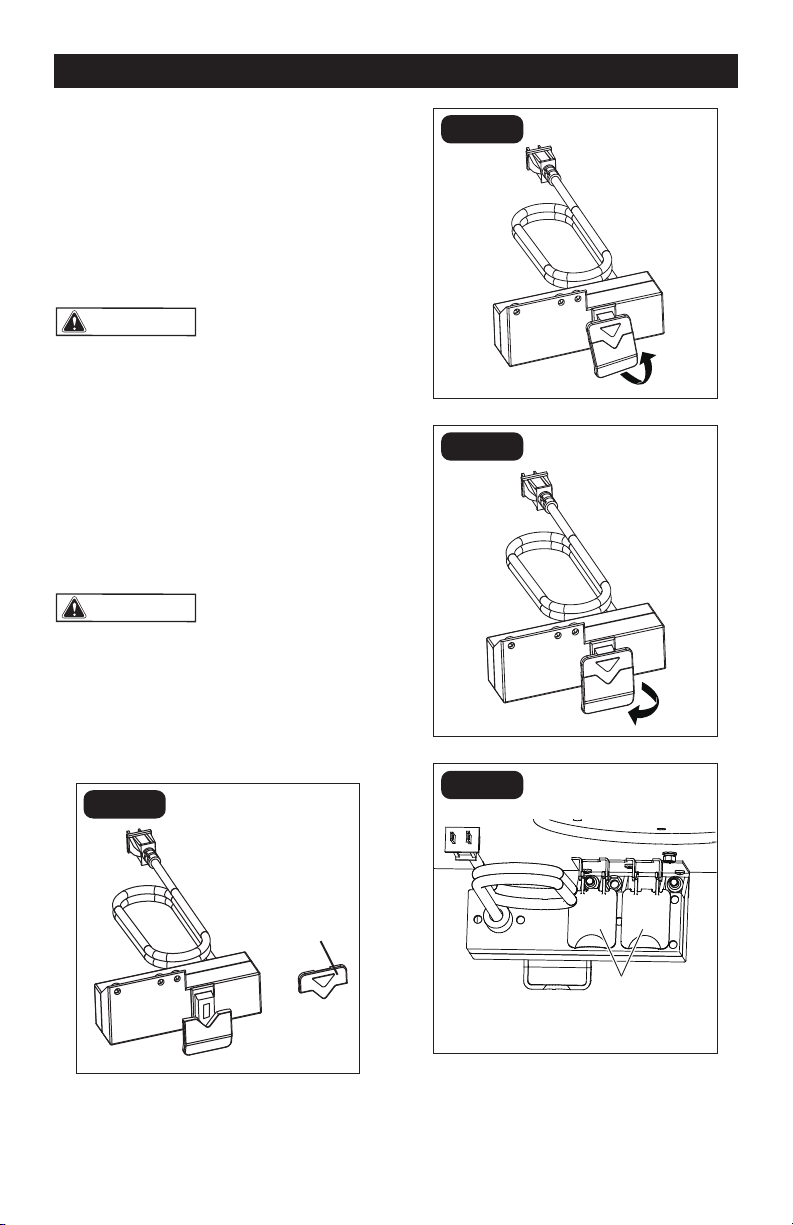
OPERATION
SWITCH OPERATION (FIG. 12-15)
Two receptacles are located at the back
of the switch assembly. Use one for
plugging in the router. The other may be used
to plug in a vacuum or a light (not included).
Two dust shields are designed to protect the
receptacles (Fig. 12)
WARNING:
To ensure safety and
reliability, when one receptacle is used for
the router, the capacity of the other
receptacle is limited to 5 A. The total
current drawn by the two devices must
not exceed 15 A.
1. Insert the safety key into the switch.
2. To turn the switch ON, pull the ON/OFF
switch up.
3. To turn the switch OFF, push the ON/OFF
switch down.
WARNING:
Never leave the router
unattended while it is running or before it
comes to a complete stop.
4. To lock switch in the OFF position, push
the ON/OFF switch down to turn the
tool OFF, and then remove the safety
key from the switch.
Safety key
Insert the safety key
Turn the router on
Turn the router off
Page 18
TO ADJUST THE EXTENDED
FENCE FORWARD AND
BACKWARD (FIG. 16)
1. Loosen the two wing nuts.
2. Move the fence forward or backward
along the slots to the desired position.
3. Tighten the wing nuts. The fence can
be moved forward and backward
3 3/4” (9.5cm).
FIG. 16
FIG. 17a
FIG. 17b
OPERATION
USING A VACUUM
The vacuum adaptor in the fence assembly
is 2 1/4" (5.7cm) in diameter. Select the
vacuum accordingly.
WARNING:
Operating the router
table without a vacuum can result in an
excessive build-up of sawdust and wood
chips under the fence assembly and
guard and in the cabinet, reducing the
performance of the router table and fence
assembly.
ADJUSTING THE FENCE
The fence supports and guides the
workpiece. To provide the best support
during routing operations, the fence facings
should be as close to the bit as possible
without contacting the bit (typically about
1/4" from the bit is a suitable distance).
TO ADJUST THE IN-FEED
AND OUT-FEED FENCE
LATERALLY (FIG. 17)
The in-feed and out-feed fence can each be
adjusted 2” (5 cm) laterally to lengthen the
fence.
1. Loosen the four wing nuts.
2. Move the fence facings right or left to the
desired position
3. Tighten the wing nuts.
Two wing nuts
Four wing nuts
Before
After
Page 19
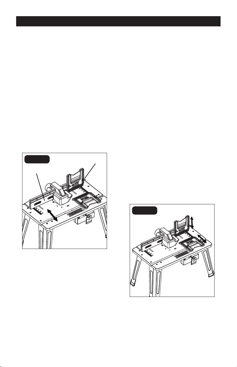
FIG. 18
FIG. 19
OPERATION
ROUTING WITH FEATHER
BOARDS (FIG. 19)
Feather boards are helpful in controlling
the workpiece while routing and assist in
keeping the workpiece at on the
tabletop. The tabletop feather board,
combined with the fence feather board, help
to keep the workpiece pressed against the
fence and tabletop. The best location for
the feather boards varies according to your
application, workpiece size, and other
factors.
1. Loosely install the feather board(s) as
described above.
2. Place the workpiece on the router table
so that it is squarely against the fence.
3. Position the feather boards snugly
against the workpiece and tighten the
wing nuts.
4. The workpiece should move with some
resistance but without requiring a great
effort.
5. For wider workpiece, the tabletop
feather board cannot be used.
TO ADJUST THE OUT-FEED
FENCE FOR JOINING (FIG. 18)
For joining operations, the out-feed fence
can be adjusted up to 1/2" (12.7 mm)
forward of the in-feed fence to support the
workpiece after it passes across the router
bit.
1. Loosen the two wing nuts on the
out-feed fence.
2. Move the out-feed fence forward of the
in-feed fence to a distance equal to the
width of material to be removed from the
workpiece. Tighten the wing nuts.
3. Move and clamp the entire extended
fence so that the out-feed fence is
aligned with the cutting edge of the bit.
Out-feed fence
In-feed fence

Page 20
USING THE ROUTER WITH THE
ROUTER TABLE
1. Read and understand entire Operator’s
Manual for the router.
2. Always plug the router into the switched
outlet in the router table. Never plug a
router-table mounted router into another
power source.
3. Make sure the router-table switch is
off. Lock the router switch in the ON
position.
4. Reconrm that all router adjustments are
securely locked before supplying power
to the router.
5. Plug the power cord for the router table
into a power source.
6. Turn on the power to the router table by
pulling up on the ON/OFF switch.
7. Always control the power to the rout-
er with the switch on the router table
whenever the router is mounted on the
table.
8. Adjust the fence to support the
workpiece to be cut.
OPERATION
NOTICE:
The workpiece must always be
held tightly against the fence.
9. Always feed the workpiece from right to
left.
WARNING:
The direction of feed
for the workpiece is always against the
sharp edges of the cutter, and into the
rotation of the cutter. When installed in a
router table, the direction of cutter
rotation is counter-clockwise. Failure
to follow this rule can result in serious
personal injury.
Page 21
A
B
FIG. 20b
OPERATION
ADJUSTING DEPTH AND HEIGHT
OF CUT (FIG. 20)
1. Unplug the router table.
2. Select a board that is smooth and
straight, with good square edges.
3. Mark lines “A” and “B” on the end of the
board, as shown in Fig. 20b.
• Line “A” indicates the desired height
of cut.
• Line “B” indicates the desired nal
depth of cut.
• The area outlined by “A,” “B” and the
edge of the board is the area that will
be cut away.
4. If the desired depth of cut can be cut in
a single pass, loosen the fence clamping
wing nuts and move the fence forward
or backward until the outermost cutting
edge of the router bit is aligned with line
“B”.
NOTICE: Never cut more than 1/8 inch
deep with a single pass.
NOTICE: For deeper cuts, do NOT attempt
to make the cut in a single pass. Make
multiple shallower cuts passes,
progressively moving the fence backward
until the desired depth of cut is reached.
5. Use the scales on the tabletop as a guide
to align the fence; then securely tighten
both fence clamping wing nuts.
WARNING:
Always make sure
that the fence and guard cannot come in
contact with the router bit. Failure to do
so will result in damage to the router table
and can cause personal injury.
6. Following the instructions that came
with your router, adjust the router height
of cut until the top of the router bit lines
up with line “A.”
7. Once all adjustments have been made,
double-check that:
• The router is securely tightened in the
router base.
• The router bit is securely tightened in
the router collet.
• The router base is securely tightened
to the router table.
8. Remove the board from the table.
NOTICE:
When making adjustments,
use a piece of scrap wood to make trial
cuts before making the cut with the actual
workpiece.
FIG. 20a
Detail
Fig. 20b
Scrap
Workpiece
Page 22
WARNING:
To ensure safety and
reliability, all repairs should be performed
by a qualied service technician at
Authorized Service Center.
WARNING:
Always wear safety
goggles or safety glasses with side
shields when using compressed air to
clean tool. If the operation is dusty, also
wear a dust mask.
WARNING:
Unplug the router
from the power source before cleaning or
performing any maintenance.
WARNING:
If the supply cord is
damaged, it must be replaced by a
specially prepared cord available through
the service organization.
MAINTENANCE
WARNING:
Do not allow brake
uids, gasoline, petroleum-based
products, penetrating oil, etc. to come
into contact with plastic parts. These
substances contain chemicals that can
damage, weaken, or destroy plastic.
Before each use:
• Inspect the router, the switch, and the
cord for damage.
• Check for damaged, missing, or worn
parts.
• Check for loose screws, misalignment
or binding of moving parts, or any
other condition that may affect the
operation.
• If abnormal vibration or noise occurs,
turn the router off immediately, and
have the problem corrected before
further use.
TROUBLESHOOTING
PROBLEM
CAUSE
SUGGESTED CORRECTIVE ACTION
The router
does not
work.
The router is not plugged into the
table outlet.
Insert router power cord plug into a
table outlet.
The router-table cord is not
connected to a power source.
Plug the router-table cord into a power
source.
The switch on the router table is in
the “OFF” position.
Insert key and pull the switch to the
ON position.
The table
surface is
not at.
The legs are not properly
assembled.
Check assembly directions, and
tighten all fasteners securely.
The work surface is not at.
Place the router table on a at, level
surface.
The router
cannot be
attached to
the table.
The sub-base and the dust
extraction adaptor is still on
the router.
Remove the plastic sub-base and dust
extraction adaptor from the router .

Page 23
NOTES

Page 24
NOTES

Page 25
NOTES

SAVE YOUR RECEIPTS
THIS WARRANTY IS VOID WITHOUT THEM
Page 26
ROUTER TABLE
WARRANTY
30-DAY MONEY BACK GUARANTEE:
This PERFORMAX
®
brand power tool carries our 30-Day Money Back Guarantee.
If you are not completely satised with your PERFORMAX
®
brand power tool
for any reason within thirty (30) days from the date of purchase, return the tool
with your original receipt to any MENARDS
®
retail store, and we will provide
you a refund – no questions asked.
2-YEAR LIMITED WARRANTY:
This PERFORMAX
®
brand power tool carries a 2-Year Limited Warranty to the
original purchaser. If, during normal use, this PERFORMAX
®
power tool breaks or
fails due to a defect in material or workmanship within two (2) years from the date
of original purchase, simply bring this tool with the original sales receipt back to
your nearest MENARDS
®
retail store. At its discretion, PERFORMAX
®
agrees to
have the tool or any defective part(s) repaired or replaced with the same or similar
PERFORMAX
®
product or part free of charge, within the stated warranty period,
when returned by the original purchaser with original sales receipt. Notwithstanding
the foregoing, this limited warranty does not cover any damage that has resulted
from abuse or misuse of the Merchandise. This warranty: (1) excludes expendable
parts including but not limited to blades, brushes, belts, bits, light bulbs, and/or
batteries; (2) shall be void if this tool is used for commercial and/or rental purposes;
and (3) does not cover any losses, injuries to persons/property or costs. This warranty
does give you specic legal rights and you may have other rights, which vary from
state to state. Be careful, tools are dangerous if improperly used or maintained.
Seller’s employees are not qualied to advise you on the use of this Merchandise.
Any oral representation(s) made will not be binding on seller or its employees. The
rights under this limited warranty are to the original purchaser of the Merchandise
and may not be transferred to any subsequent owner. This limited warranty is in lieu
of all warranties, expressed or implied including warranties or merchantability and
tness for a particular purpose. Seller shall not be liable for any special, incidental,
or consequential damages. The sole exclusive remedy against the seller will be for
the replacement of any defects as provided herein, as long as the seller is willing or
able to replace this product or is willing to refund the purchase price as provided
above. For insurance purposes, seller is not allowed to demonstrate any of these
power tools for you.
For questions / comments, technical assistance or repair parts –
Please Call Toll Free at: 1-866-858-2664 (M-F 8:30am – 5:00pm EST)

Page 27
03/2016
© 2016 Menard, Inc., Eau Claire, WI 54703