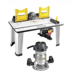
Router Combo Kit
241-1464
For questions / comments, technical assistance or repair parts –
Please Call Toll Free: 1-866-858-2664. (M-F 8:30am-5:00pm Est.)
OPERATOR’S MANUAL
CAUTION:
To Reduce The Risk Of Injury, User Must Read And
Understand Operator’s Manual. Save These Instructions For Future
Reference.

TABLE OF CONTENTS
Safety Symbols ......................................................... Page 2
Safety Instructions ...................................................... Page 3
Overview/Specifications ................................................. Page 7
Assembly ............................................................. Page 9
Operation ............................................................ Page 13
Maintenance .......................................................... Page 25
Troubleshooting ....................................................... Page 26
Warranty ............................................................. Page 30
Page 2
SAFETY SYMBOLS
Some of these following symbols may be used on this tool. Please study them and learn their
meaning. Proper interpretation of these symbols will allow you to operate the tool better and
more safely.
Symbol
Name
Designation / Explanation
V Volts Voltage
A Amperes Current
Hz Hertz Frequency (cycles per second)
W Watts Power
∿
Alternating current Type of current
�
Direct current Type or characteristic of current
n
o
No-load speed Rotational speed at no load
lbs Pounds Weight
Class II construction Double insulated construction
.../min Per minute
Revolutions, strokes, surface speed
orbits, etc., per minute
Wear safety goggles
WARNING:
The operation of
any power tool can result in foreign
objects being thrown into your eyes,
which can result in severe eye damage.
Before beginning power tool operation,
always wear safety goggles or safety
glasses with side shields and a full-face
shield when needed. We recommend a
Wide Vision Safety Mask for use over
eyeglasses or standard safety glasses
with side shields. Always use eye
protection which is marked to comply
with ANSI Z87.1.
WARNING:
To ensure safety and reliability, all repairs should be performed by a
qualied service technician.

Page 3
SAFETY INSTRUCTIONS
The purpose of safety symbols is to attract your attention to possible dangers. The safety
symbols, and the explanations with them, deserve your careful attention and understanding.
The symbol warnings do not, by themselves, eliminate any danger. The instructions and
warnings they give are no substitutes for proper accident prevention measures.
WARNING:
Be sure to read and understand all safety instructions in this manual,
including all safety alert symbols such as “DANGER,” “WARNING” and “CAUTION” before
using this tool. Failure to following all instructions listed below may result in electric
shock, re, and/or serious personal injury.
SYMBOL MEANING
SAFETY ALERT SYMBOL: Indicates DANGER, WARNING, OR CAUTION.
May be used in conjunction with other symbols or pictographs.
DANGER:
Indicates an imminently hazardous situation, which, if not avoided,
will result in death or serious injury.
WARNING:
Indicates a potentially hazardous situation, which, if not avoided,
could result in death or serious injury.
CAUTION:
Indicates a potentially hazardous situation, which, if not avoided, could
result in minor or moderate injury.
NOTICE: (Without Safety Alert Symbol) Indicates a situation that may result in property
damage.
SAVE THESE INSTRUCTIONS!

Page 4
SAFETY INSTRUCTIONS
GENERAL POWER TOOL
SAFETY WARNINGS
WARNING:
Read all safety
warnings and all instructions. Failure to follow
the warnings and instructions may result in
electric shock, fire and/or serious injury.
Save all warnings and instructions for
future reference.
The term “power tool” in the warnings refers
to your mains-operated (corded) power tool
or battery-operated (cordless) power tool.
WORK AREA SAFETY
1. Keep work area clean and well lit.
Cluttered and dark areas invite accidents.
2. Do not operate power tools in explosive
atmospheres, such as in the presence of
ammable liquids, gases or dust. Power
tools create sparks which may ignite the
dust or fumes.
3. Keep children and bystanders away
while operating a power tool. Distractions
can cause you to lose control
ELECTRICAL SAFETY
1. Power tool plugs must match the
outlet. Never modify the plug in any way.
Do not use any adapter plugs with earthed
(grounded) power tools. Unmodified plugs
and matching outlets will reduce risk of
electric shock.
2. Avoid body contact with earthed
or grounded surfaces, such as pipes,
radiators, ranges and refrigerators. There
is an increased risk of electric shock if your
body is earthed or grounded.
3. Do not expose power tools to rain or
wet conditions. Water entering a power tool
will increase the risk of electric shock.
4. Do not abuse the cord. Never use the
cord for carrying, pulling or unplugging the
power tool. Keep cord away from heat, oil,
sharp edges or moving parts. Damaged or
entangled cords increase the risk of electric
shock.
5. When operating a power tool outdoors,
use an extension cord suitable for outdoor
use. Use of a cord suitable for outdoor use
reduces the risk of electric shock.
6. If operating a power tool in a damp
location is unavoidable, use a ground-fault
circuit interrupter (GFCI) protected supply.
Use of a GFCI reduces the risk of electric
shock.
PERSONAL SAFETY
1. Stay alert, watch what you are doing
and use common sense when operating a
power tool. Do not use a power tool while
you are tired or under the inuence of
drugs, alcohol or medication. A moment of
inattention while operating power tools may
result in serious personal injury.
2. Use personal protective equipment.
Always wear eye protection. Protective
equipment such as dust mask, non-skid
safety shoes, hard hat, or hearing protection
used for appropriate conditions will reduce
personal injuries.
3. Prevent unintentional starting. Ensure
the switch is in the off-position before
connecting to power source and/or battery
pack, picking up or carrying the tool.
Carrying power tools with your finger on the
switch or energising power tools that have
the switch on invites accidents.
4. Remove any adjusting key or wrench
before turning the power tool on. A wrench
or a key left attached to a rotating part of the
power tool may result in personal injury.
5. Do not overreach. Keep proper footing
and balance at all times. This enables better
control of the power tool in unexpected
situations.
6. Dress properly. Do not wear loose
clothing or jewellery. Keep your hair,
clothing and gloves away from moving
parts. Loose clothes, jewellery or long hair
can be caught in moving parts.

Page 5
7. If devices are provided for the
connection of dust extraction and
collection facilities, ensure that these are
connected and properly used. Use of these
devices can reduce dust-related hazards.
POWER TOOL USE AND CARE
1. Do not force the power tool. Use the
correct power tool for your application.
The correct power tool will do the job better
and more safely at the rate for which it was
designed.
2. Do not use the power tool if the switch
does not turn it on and off. Any power tool
that cannot be controlled with the switch is
dangerous and must be repaired.
3. Disconnect the plug from the power
source and/or the battery pack from the
power tool before making any adjustments,
changing accessories, or storing power
tools. Such preventive safety measures
reduce the risk of starting the power tool
accidentally.
4. Store idle power tools out of the reach
of children and do not allow persons
unfamiliar with the power tool or these
instructions to operate the power tool.
Power tools are dangerous in the hands of
untrained users.
5. Maintain power tools. Check for
misalignment or binding of moving parts,
breakage of parts and any other condition
that may affect the power tool’s operation.
If damaged, have the power tool repaired
before use. Many accidents are caused by
poorly maintained power tools.
6. Keep cutting tools sharp and clean.
Properly maintained cutting tools with sharp
cutting edges are less likely to bind and are
easier to control.
7. Use the power tool, accessories,
tool bits, etc. in accordance with these
instructions, taking into account the
working conditions and the work to be
performed. Use of the power tool for
operations different from those intended
could result in a hazardous situation.
SERVICE
1. Have your power tool serviced by a
qualied repair person using only identical
replacement parts. This will ensure that the
safety of the power tool is maintained.
SAFETY GUIDELINES FOR
ROUTERS
1. Hold the power tool by insulated
gripping surfaces only, because the cutter
may contact its own cord. Cutting a “live”
wire may make exposed metal parts of the
power tool “live” and could give the operator
an electric shock.
2. Use clamps or another practical way
to secure and support the workpiece to a
stable platform. Holding the work by your
hand or against the body leaves it unstable
and may lead to loss of control.
ADDITIONAL SAFETY
GUIDELINES FOR ROUTERS
1. Always make sure the work surface is
free from nails and other foreign objects.
Cutting into a nail can cause the bit and the
tool to jump and damage the bit.
2. Never hold the workpiece in one hand
and the tool in the other hand when in use.
Never place hands near or below cutting
surface. Clamping the material and guiding
the tool with both hands is safer.
3. Never lay workpiece on top of hard
surfaces, like concrete, stone, etc..
Protruding cutting bit may cause tool to
jump.
4. Always wear safety goggles and dust
mask. Use only in well ventilated area.
Using personal safety devices and working
in safe environment reduces risk of injury.
5. Keep handles dry, clean and free from
oil and grease. Slippery hands cannot safely
control the power tool.
SAFETY INSTRUCTIONS

Page 6
6. After changing the bits or making any
adjustments, make sure the collet nut and
any other adjustment devices are securely
tightened. Loose adjustment device can
unexpectedly shift, causing loss of control,
loose rotating components will be violently
thrown.
7. Never start the tool when the bit is
engaged in the material. The bit cutting
edge may grab the material causing loss of
control of the cutter.
8. Always hold the tool with two hands
during start-up. The reaction torque of the
motor can cause the tool to twist.
9. The direction of feeding the bit into
the material is very important and it
relates to the direction of bit rotation.
When viewing the tool from the top, the
bit rotates clockwise. Feed direction of
cutting must be counter-clockwise. NOTE:
inside and outside cuts will require different
feed direction, refer to section on feeding
the router. Feeding the tool in the wrong
direction, causes the cutting edge of the bit
to climb out of the work and pull the tool in
the direction of this feed.
10. Never use dull or damaged bits. Sharp
bits must be handled with care. Damaged
bits can snap during use. Dull bits require
more force to push the tool, possibly
causing the bit to break.
11. Never touch the bit during or
immediately after the use. After use the bit
is too hot to be touched by bare hands.
12. Never lay the tool down until the motor
has come to a complete standstill. The
spinning bit can grab the surface and pull
the tool out of your control.
13. Never use bits that have a cutting
diameter greater than the opening in the
base.
14. Your router can also be used in the
router tables listed as below. Carefully
read the Instruction Manuals for the router
tables before operation.
Router Router table
241-1464
(PERFORMAX router)
KOBALT: 857432
SKIL: RAS900
BOSCH: 2429294,
2429295
CRAFTSMAN:
37599, 39595,
37610, 37596
PERFORMAX:
2411462
MASTERFORCE:
2410833
WARNING:
Some dust created by
power sanding, sawing, grinding, drilling
and other construction activities contains
chemicals known to the state of California
to cause cancer, birth defects or other
reproductive harm. Some examples of
these chemicals are:
• Lead from lead-based paints
• Crystalline silica from bricks and
cement and other masonry products,
and
• Arsenic and chromium from chemically-
treated lumber.
Your risk from these exposures varies,
depending on how often you do this type
of work. To reduce your exposure to these
chemical: work in a well ventilated area,
and work with approved safety equipment,
such as those dust masks that are specially
designed to filter out microscopic particles.
SAFETY INSTRUCTIONS
Page 7
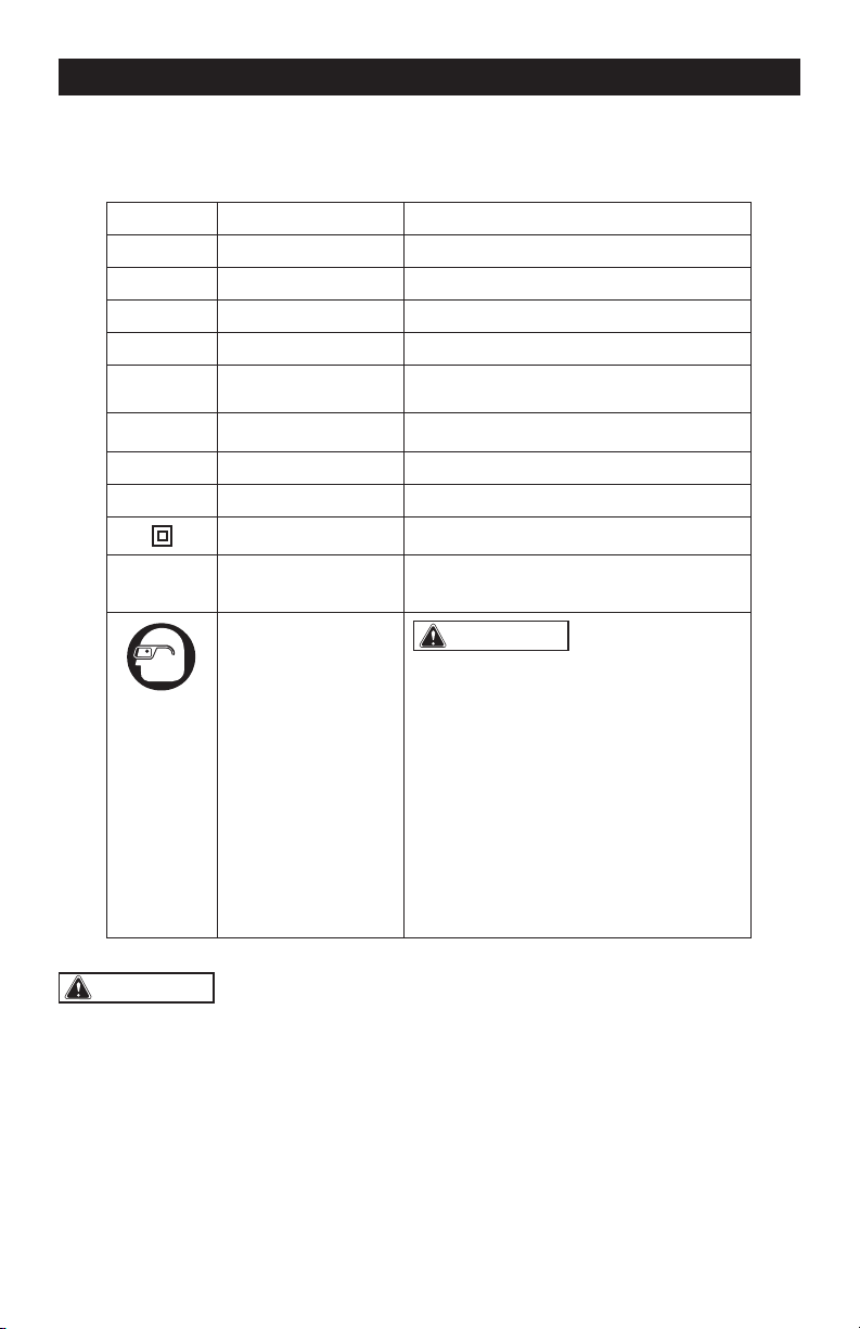
OVERVIEW
ON
O
OFF
Variable-speed dial
ON/OFF switch
Handle
Collet
Lock nut
Power indicator
Plunge-depth
locking lever
Base plate
Dust-extraction
adaptor
Coarse-adjustment
notches
Motor clamp
Depth-stop turret
Spindle-lock button
LED worklight
Adjustment bar
Handle
Fine-adjustment dial
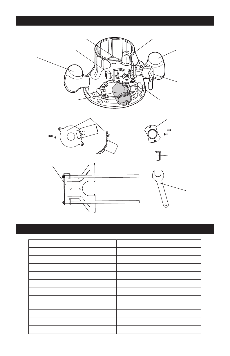
Page 8
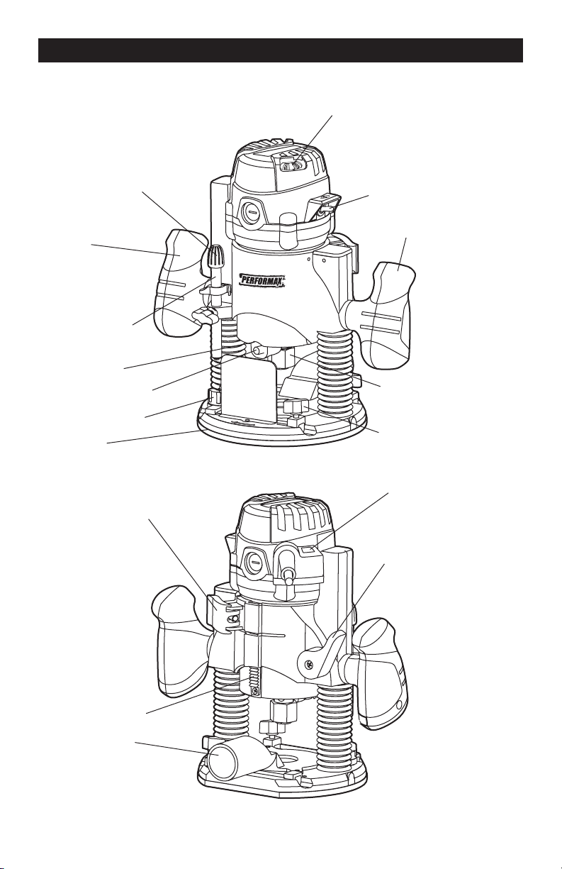
OVERVIEW
Slot
Fine-adjustment dial
Handle
Motor clamp
Lock nut
Pattern guide
1/4” Collet
Collet wrench
Straight-edge guide
Dust-extraction adaptor
Dust-extraction adaptors
Coarse-adjustment button
Handle
SPECIFICATIONS
Rated voltage 120 V~ 60 Hz
Rated power Input 11 A
Max HP 2.0 HP
Speed 11,000–25,000 RPM
Collet capacity 1/4” & 1/2”
Fixed base range 1-3/4”
Plunge stroke 2-1/4”
Base dimension
Fixed base 6”
Plunge base 6-11/16”
Inside base diameter 2”
Micro-fine depth Fixed base adjusts to 1/64”
Weight 12 lbs. (5.4 kg)
Page 9
WARNING:
If any part is broken
or missing, DO NOT attempt to plug in the
power cord or operate the tool until the
broken or missing part is replaced. Failure
to do so could result in possibly serious
injury.
WARNING:
Do not attempt to
modify this tool or create accessories not
recommended for use with this tool. Any
such alteration or modication is misuse
and could result in a hazardous condition
leading to possible serious injury.
WARNING:
Your tool should
never be connected to the power source
when you are assembling parts, making
adjustments, installing or removing
blades, cleaning, or when it is not in
use. Disconnecting the tool will prevent
accidental starting, which could cause
serious personal injury.
CONTENTS
Router, plunge base, fixed base, collets,
collet wrench, straight-edge guide, pattern
guide, 2 dust-extraction adaptors and
instruction manual.
UNPACKING
1. Carefully remove the tool and any
accessories from the carton. Make sure
that all items listed in the packing list are
included.
2. Inspect the tool carefully to make sure
that no breakage or damage occurred
during shipping.
3. Do not discard the packing material
until you have carefully inspected and
satisfactorily operated the tool.
SELECTING THE CUTTER BIT
This router comes with 1/2”collet and 1/4”
collet sleeve that accept cutter bits with
1/2” and 1/4” shanks, respectively. The 1/2”
collet is installed on the tool; the 1/4” collet
sleeve can be installed inside of the 1/2”
collet.
INSTALLING THE 1/4” COLLET
SLEEVE (FIG. 1-2)
1. Disconnect the plug from the power
supply.
2. Remove the router motor from the
base; refer to the section “REMOVING
MOTOR FROM BASE”.
3. Set the router motor upside down on its
top cap, with the collet pointing up.
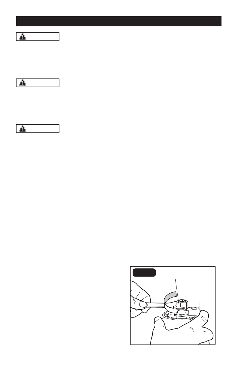
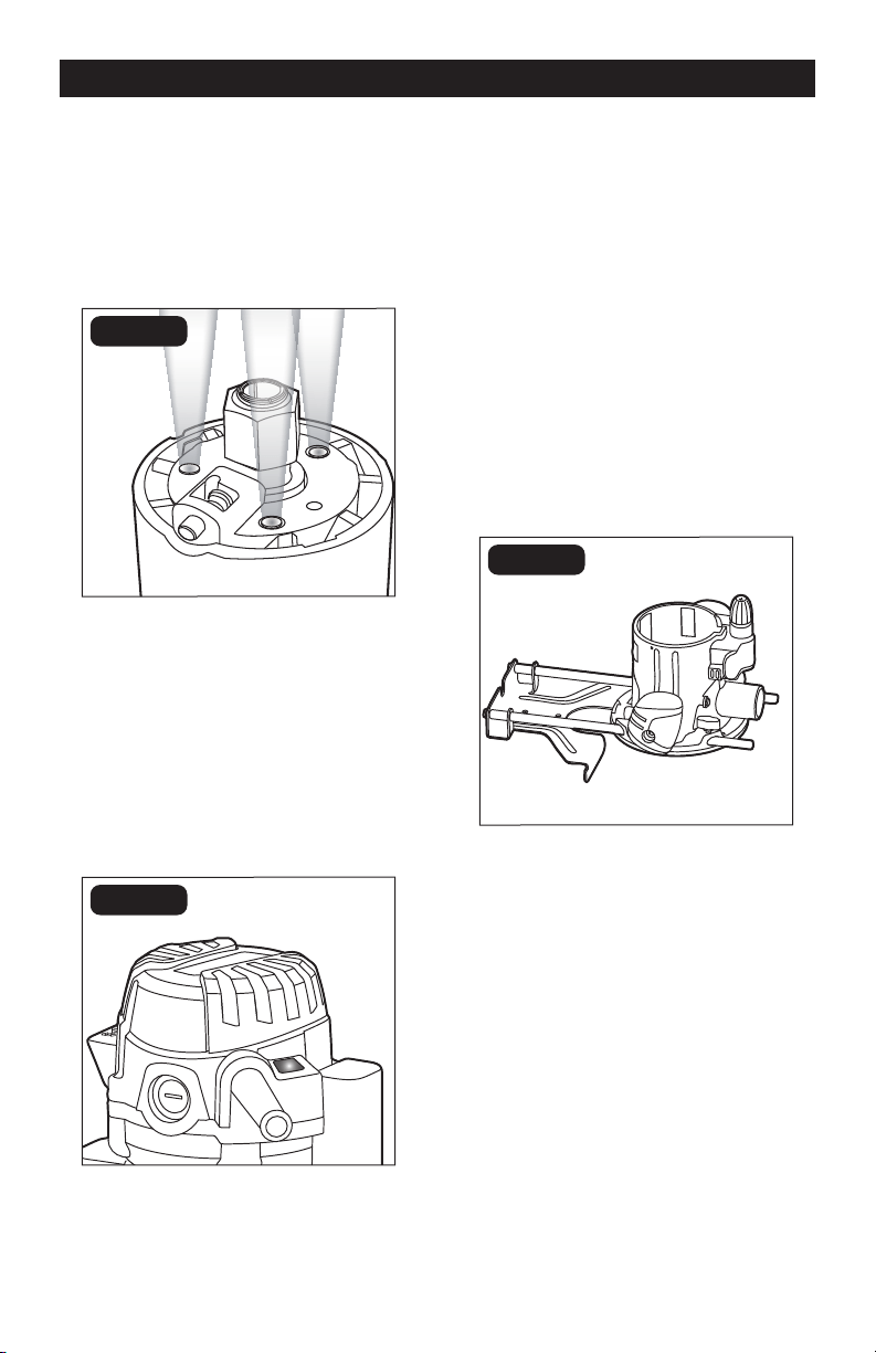
4. Press the spindle-lock button to engage
and lock the spindle shaft and collet nut
(FIG. 1).
5. Place the collet wrench on the collet nut
and turn it counterclockwise to loosen
the collet nut slightly to accept the
cutter bit shank.
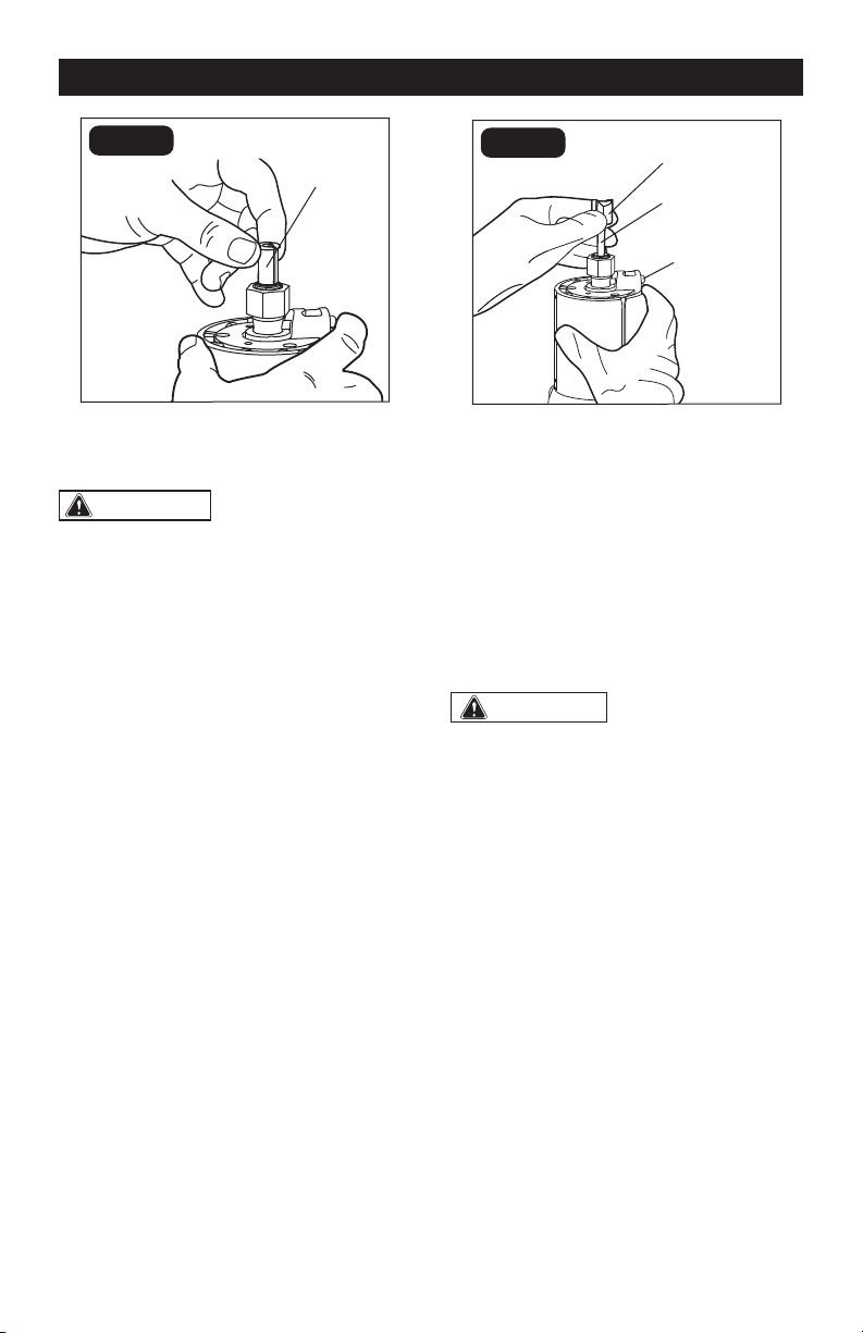
6. Insert the 1/4” collet sleeve into the 1/2”
collet assembly as far as it will go (FIG. 2).
7. With the 1/4” collet sleeve inserted
and the spindle-lock button pressed
in to engage the shaft, place the collet
wrench on the collet nut and turn it
clockwise until the 1/4” collet sleeve is
tightened on the 1/2” collet nut.
FIG. 1
Collet nut
Spindle-
lock button
ASSEMBLY
Page 10
FIG. 2
1/4” Collet
REPLACING THE CUTTER BIT
CAUTION:
Always ensure that
the tool is switched OFF and unplugged
from the power supply before installing or
removing bits or accessories.
INSTALLING THE CUTTER BIT
(FIG. 3)
1. Disconnect the plug from the power
supply.
2. Remove the router motor from the
base; refer to the section “REMOVING
MOTOR FROM BASE”.
3. Set the router motor upside down on its
top cap, with the collet pointing up.
4. Press the spindle-lock button to engage
and lock the spindle shaft and collet nut.
5. Place the collet wrench on the collet nut
and turn it counterclockwise to loosen
the collet nut slightly in order to accept
the cutter bit shank.
6. Insert the cutter bit shank into the
collet assembly as far as it will go, then
back the shank out until the cutters are
approximately 1/8” to 1/4” away from
the face of the collet (FIG. 3).
FIG. 3
Cutters
Bit shank
Spindle-lock
button
7. With the cutter bit inserted and the
spindle-lock button pressed in to engage
the shaft, place the collet wrench on the
collet nut and turn it clockwise until the
cutter bit is firmly tightened on the collet
nut.
NOTICE: To ensure proper gripping of the
cutter bit shank and minimize run-out, the
shank of the cutter bit must be inserted
into the collet nut at least 5/8”.
WARNING:
Tighten the collet nut
securely to prevent the cutter bit from
slipping. If the collet nut is not securely
tightened, the cutter bit may detach
during use, causing serious personal
injury.
REMOVING THE CUTTER BIT
1. Disconnect the plug from the power
supply.
2. Remove the router motor from the
base; refer to the section “REMOVING
MOTOR FROM BASE”.
3. Set the motor upside down on its top
cap, with the collet pointing up.
4. Press the spindle-lock button to engage
and lock the spindle shaft and collet nut.
5. Place the wrench on the collet nut and
turn it counterclockwise to loosen the
collet nut slightly.
6. Remove the cutter bit shank.
ASSEMBLY
Page 11
INSTALLING MOTOR IN BASE
INSTALLING MOTOR IN FIXED
BASE (FIG. 4)
WARNING:
Never use the router
motor without installing it into an approved
base. Failure to do so could result in serious
personal injury and damage to motor.
NOTICE: Before installing the motor
housing in the xed base, have the collet
nut and router cutter bit installed on
the motor housing; refer to the section
“REPLACING THE CUTTER BIT”.
CAUTION:
Always ensure that
the tool is switched OFF and unplugged
from the power supply before installing or
removing bits or accessories.
1. Disconnect the plug from the power
supply.
2. Place the fixed base on a flat surface.
3. With the back of fixed base facing you,
open the motor clamp.
4. Press in the coarse-adjustment button
while you align the coarse-adjustment
notches on the motor with the slot in the
fixed base.
5. Slide the motor down into the fixed base.
6. The router motor will now slide up or
down to set adjustments when the
coarse-adjustment button is pressed in.
7. After all adjustments are made, close
the router clamp securely.
FIG. 4
Slot
Coarse-
adjustment
button
Coarse- adjustment
notches
Motor
clamp
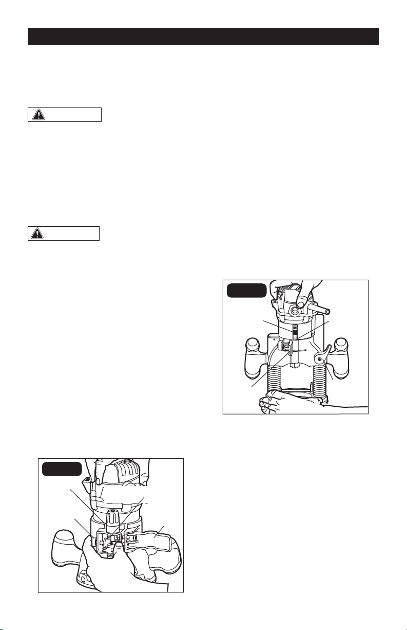
INSTALLING MOTOR IN PLUNGE
BASE (FIG. 5)
1. Disconnect the plug from the power
supply.
2. Place the plunge base on a flat surface.
3. With the back of the plunge base facing
you, open the motor clamp and make
sure that the plunge action is in the “UP”
position, with the plunge-lock lever
locked.
4. With the coarse-adjustment notches on
the motor aligned with the plunge-base
slot, lower the motor housing into the
plunge base, engaging the tab into the
slot.
5. Slide the motor into the base as far as it
will go.
6. Close the motor clamp securely.
FIG. 5
Coarse-
adjustment
notches
Motor
clamp
Slot
Lock
lever
REMOVING MOTOR FROM BASE
REMOVING MOTOR FROM THE
FIXED BASE (FIG. 4)
1. Disconnect the plug from the power
supply.
2. Place the router on a flat surface.
3. With the back of the router facing you,
open the router motor clamp.
4. Push in the coarse-adjustment button
while you lift router motor out of the
fixed base.
5. Set the motor upside down on its top
cap with the collet pointing up and
remove cutter bit.
ASSEMBLY
Page 12
REMOVING MOTOR FROM THE
PLUNGE BASE (FIG. 5)
1. Disconnect the plug from the power
supply.
2. Place the router on a flat surface.
3. With the back of the plunge base facing
you, open the motor clamp and make
sure that the plunge action is in the
“UP” position with the plunge-lock lever
locked.
4. Lift the motor straight up out of the
base, sliding the coarse-adjustment
notches on the motor free from the slot
in the plunge base.
5. Set the motor upside down on its top
cap with the collet pointing up and
remove the cutter bit.
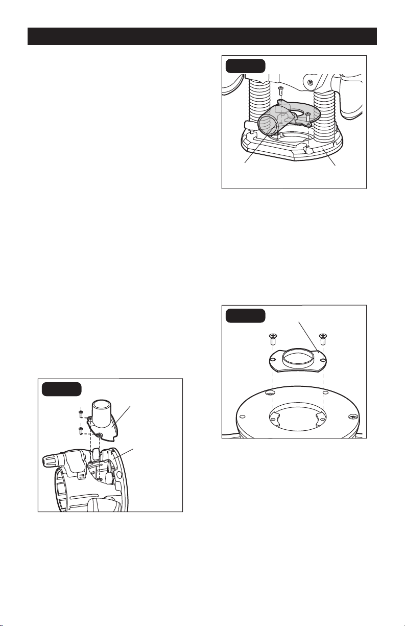
INSTALLING THE
DUST-EXTRACTION
ADAPTOR (FIG. 6-7)
To attach the dust-extraction adaptor onto
either the fixed or plunge base, position
and secure it to the base with the screws
(included); as shown in FIG. 6-7.
FIG. 6
Dust-extraction
adaptor
Fixed base
FIG. 7
Dust-extraction
adaptor
Plunge base
INSTALLING THE PATTERN
GUIDE (FIG. 8)
To attach the pattern guide onto either the
fixed or plunge base, position and secure it
to the base with the screws (included); as
shown in FIG. 8.
FIG. 8
Pattern guide
ASSEMBLY

Page 13
ADJUSTING THE DEPTH OF CUT
WARNING:
Your router should
never be turned on or be connected to the
power source when you are assembling
parts, making adjustments, installing
or removing collets/nuts and cutter
bits, cleaning or when it is not in use.
Disconnecting the router will prevent
accidental starting, which could cause
serious personal injury.
DEPTH ADJUSTMENT WITH
FIXED BASE (FIG. 9)
NOTICE: All depth adjustments on the
xed base must be made with the motor
clamp open.
NOTICE: For all xed base routers, the
cutter bit depth equals the amount of the
cutter that is exposed below the surface
of the sub-base.
The fixed base is designed with a fine-
adjustment system. When the bit is lowered
to the approximate position desired (coarse
setting), the system can then be micro-
adjusted to the precise depth.
FIG. 9
Fine-
adjustment
dial
Depth-indicator
ring
COARSE ADJUSTMENT:
Depressing the coarse-adjustment button
allows you to quickly lower or raise the
cutter bit to an approximate depth setting.
FINE ADJUSTMENTS:
NOTICE: Be sure that the worm gear
system is engaged before making ne
adjustments. Test it by rotating the ne-
adjustment dial to check that the bit
lowers and raises. If it does not, press in
the coarse-adjustment button and turn
the ne-adjustment dial until the gears
engage, then reset zero “0” on the depth-
indicator ring.
The depth-indicator ring located on the
fine-adjustment dial is marked in 1/64”
increments. Turning the fine-adjustment dial
clockwise 180º (1/2 turn), lowers the cutter
bit 1/16”. One full turn clockwise 360° (zero
“0” to zero “0”) lowers the bit 1/8”.
The system allows a maximum of 17 full 360º
revolutions clockwise, to lower the cutter bit
a total of 2 1/8 inch (54mm).
The depth-indicator ring may be reset to zero
“0” without moving the fine-adjustment dial.
This allows the user to begin adjustments
from any reference point desired.
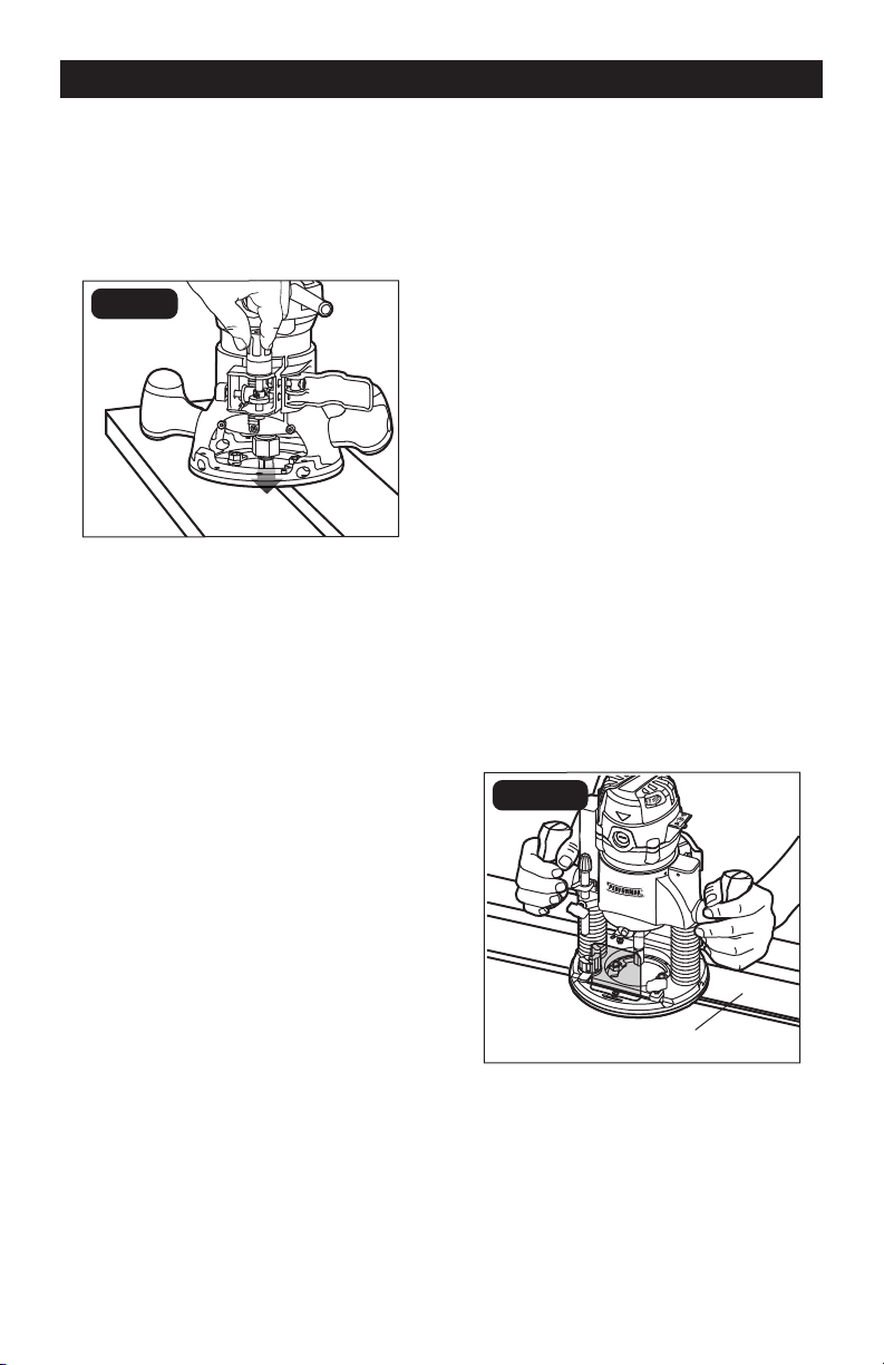
ADJUSTING DEPTH (FIG. 10)
1. Disconnect the plug from the power
supply.
2. Place the router on a flat surface with
the back of the fixed base facing you.
Open the motor clamp.
3. With the cutter bit already installed,
press in the coarse-adjustment button
and lower the motor into the base until
the cutter bit is close to the flat surface
on which the base is sitting. Turn the
fine-adjustment dial until the cutter bit
“just” touches the flat surface on which
the base is sitting. Then lock the motor
clamp.
4. Place the router on two level pieces of
wood, positioned so that the cutter bit
can be lowered below the sub-base
(FIG. 10).
OPERATION
Page 14
5. Turn the fine-adjustment dial clockwise
to lower the bit to the desired depth of
cut. Turn the dial counterclockwise to
raise the cutter bit.
6. Once the depth of cut is set, close the
motor clamp securely.
FIG. 10
DEEP CUTS
The proper cutting depth for each pass,
is always determined by the material, the
cutter bit size and type, and the power of
the motor.
Always make several progressively deeper
cuts by starting at one depth and then
making several passes, each time increasing
the cutting depth until your desired depth is
reached.
Making a cut that is too deep will stress the
motor and the cutter bit, and it may burn the
workpiece and dull the cutter bit. It could
also “grab” too much of the workpiece
and cause you to lose control of the router,
causing a serious accident.
To be certain that your depth settings are
correct, always make test cuts in scrap
material similar to your workpiece before
beginning your final cutting.
Remember, knowing the right depth for each
cut comes with routing experience.
OPERATION
DEPTH ADJUSTMENT WITH THE
PLUNGE BASE
PLUNGING ACTION (FIG. 11)
The plunge base feature simplifies depth
adjustments and allows the cutter bit to be
accurately lowered into the workpiece for
more precise set-ups.
To lower the cutter bit, release the plunge-
lock lever by moving it up to the unlocked
position.
Apply an even, downward pressure on the
plunge action until the cutter bit reaches the
desired depth, then move the plunge-lock
lever “down” to the locked position.
To raise the bit and the plunge action, unlock
the plunge-lock lever and the cutter bit and
the plunge action will automatically retract
from the workpiece and return to the raised
position.
Always have the plunge action in the raised
position and locked when the bit is not
cutting in the workpiece.
FIG. 11
Slot cutting
Page 15
PLUNGE ACTION WITH DEPTH-
STOP ROD AND DEPTH-STOP
TURRET (FIG. 12)
The depth-stop rod and the depth-stop
turret are used to control the plunge action
cutting depth as follows:
1. Disconnect the plug from the power
supply.
2. Place the router on a flat surface.
3. With the cutting bit already installed,
lower the plunge action until the cutter bit
makes contact with the flat, level surface
on which the router is sitting. Lock the
plunge-depth locking lever. This position
is ZERO - “0”: the point from which further
depth adjustments can be made.
4. To set a desired depth-of-cut, rotate the
depth-stop turret until the lowest step
of the turret is aligned directly under
the depth-stop rod (FIG. 12). Loosen
the depth-rod locking knob and lower
the depth-stop rod until it contacts the
lowest step on the turret.
5. Slide the clear plastic depth indicator
until the red line on the indicator is lined
up with ZERO – “0” marked in black on
the bottom of the depth scale. (This is
now the indicating point at which the bit
makes contact with the workpiece).
6. To set a desired cutting depth, slide the
depth-stop rod up until the red line on
the clear plastic depth indicator points
to your desired cutting depth on the
depth scale. Secure the depth-stop rod
at this position by tightening the depth-
rod locking knob.
7. Unlock the plunge-depth locking lever
to allow the bit to automatically retract
to the up position.
8. The desired depth-of-cut may now be
achieved by plunging the router down
until the depth-stop rod contacts the
selected step on the depth-stop turret.
NOTICE: When making depth adjustments
on the plunge base, the motor clamp
should always be closed securely.
FIG. 12
Plunge-depth
locking lever
Depth-stop rod
locking knob
Depth-stop
rod
Depth-stop
turret
Depth
scale
Plastic depth
indicator
USING THE DEPTH-STOP
TURRET TO SET UP DEEP
CUTS (FIG. 13)
NOTICE: Making a single deep cut is
never advisable. Smaller diameter cutter
bits are easily broken by too much side
thrust and torque. Larger cutter bits will
cause a rough cut and be difcult to guide
and control. For these reasons, do not
exceed 1/8” depth of cut in a single pass.
To produce deep cuts, always make several,
progressively deeper cuts by starting with the
highest step on the depth-stop turret, and,
after each cut, rotate the turret to the next
lower step until the lowest step is reached.
Each of the steps progresses by 1/4”
increments. The 4 steps represent a total of
“0” inch to 3/4” with a full 360º rotation of
the turret. Repeat this process if necessary.
FIG. 13
Fine-
adjustment
dial
Depth-stop
turret
OPERATION
Page 16
OPERATION
MICRO-ADJUSTMENTS WITH
THE DEPTH-STOP ROD AND
DEPTH-STOP TURRET
The depth-stop rod has a micro-adjustment
knob that turns a screw (inside the rod) either
clockwise or counterclockwise to lower or
raise the depth-stop rod on the turret for
micro-fine adjustments of the plunge depth.
Each complete revolution of the micro-
adjustment knob adjusts the plunging depth
by approximately 1/32”.
A reference indicator line is marked into the
depth-stop rod under the micro-adjustment
knob to set a reference point of “0”.
When adjusting the plunge depth, always
make sure that the micro-adjustment knob
has been turned down (clockwise) several
revolutions from the top before setting the
depth-stop rod and depth-stop turret.
Always set your micro-adjustments with the
plunge action locked in the raised (or up)
position.
To use the micro-adjustment knob after the
depth rod and turret have been set, check the
final depth setting and micro-adjust as follows:
• To micro-increase the plunge depth,
raise the micro-adjustment screw by
turning the knob counterclockwise the
desired amount.
• To micro-reduce the plunge depth,
lower the micro-adjustment screw by
turning the knob clockwise the desired
amount.
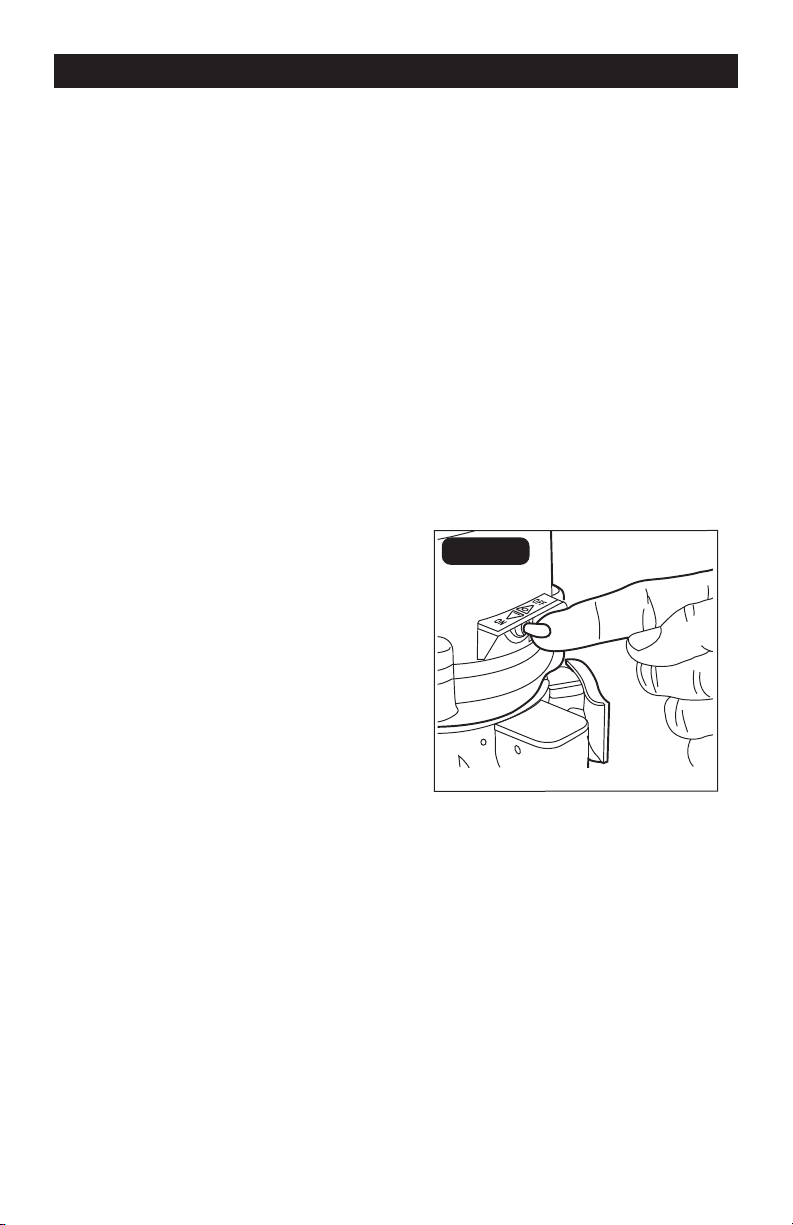
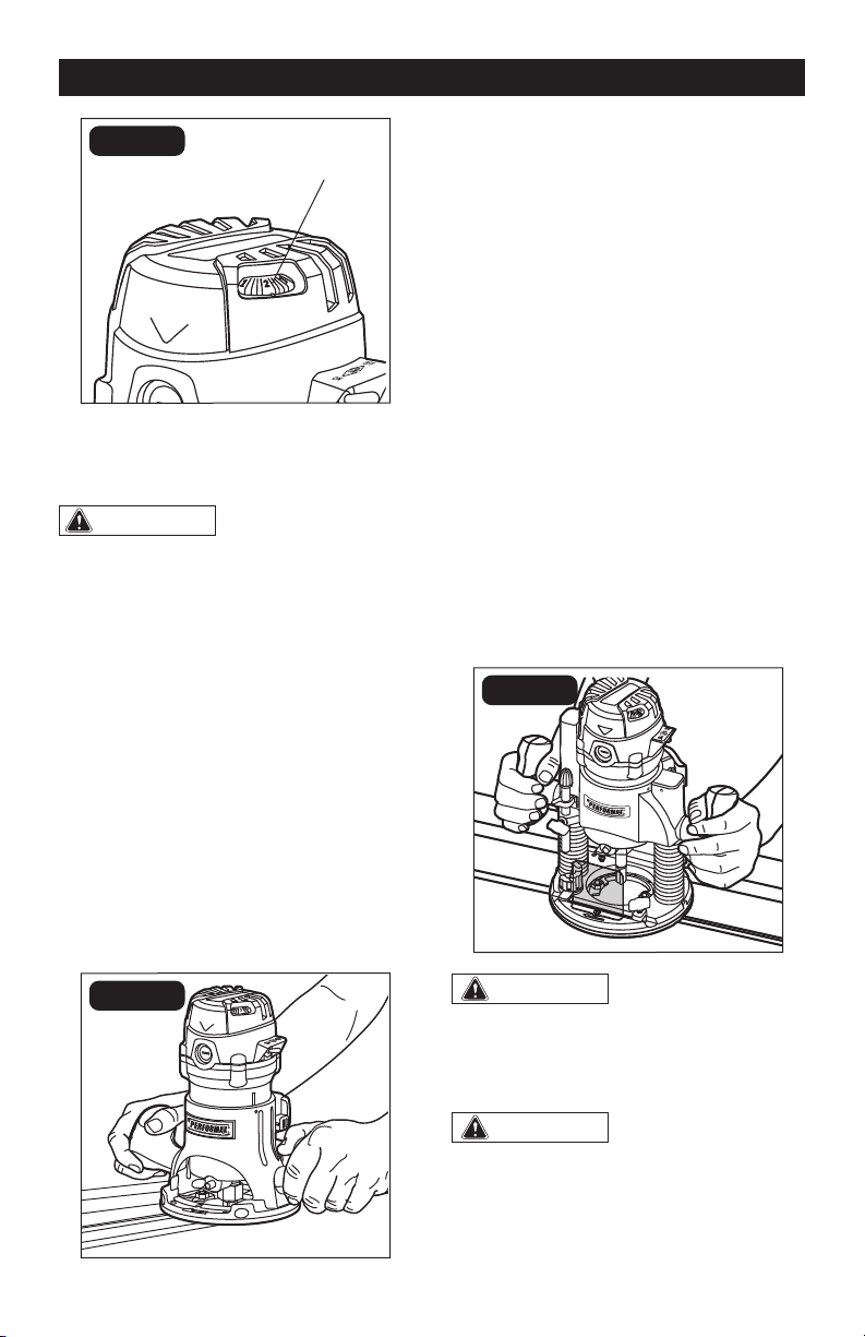
TOGGLE “ON/OFF”
SWITCH (FIG. 14)
Your router motor is turned “ON” and “OFF”
with the toggle switch located on the top
cap of the motor housing.
The left side of the toggle switch hood (as you
face it) is marked “I” and “ON” and the right
side (as you face it) is marked “O” and “OFF.”
• To turn the motor “ON”, push the toggle
switch to the left side marked “I” and
“ON.”
• To turn the motor “OFF” push the
toggle switch to the right side marked
“O” and “OFF.”
When using the fixed base or when using the
plunge base for edge routing, always hold
the router and the cutter bit away from the
workpiece when turning the toggle switch
“On.” Only contact the workpiece with the
router and cutter bit after the router has
reached the full selected speed; read and
follow the instructions for EDGE ROUTING
and INTERNAL ROUTING with the base
you are using. Only remove the router and
cutter bit from the workpiece after turning
the router motor “OFF” and after the cutter
bit comes to a complete stop.
FIG. 14
SOFT START FEATURE
The soft start control minimizes torque
twist, customary in larger router motors, by
limiting the speed at which the motor starts.
This increases the motor’s life.
Page 17
LED WORKLIGHTS (FIG. 15)
Your router motor has 3 built-in worklights
located around the collet/nut to provide
high visibility of the workpiece when cutting.
These lights are always “On” when the
toggle switch is in the “ON” position.
FIG. 15
“LIVE TOOL INDICATOR” LIGHT
(FIG. 16)
Your router also has a “live tool indicator”
green light, located on the motor housing
top cap where the power cord enters the
motor housing. This green light is always
on when the router motor is plugged into a
power source.
FIG. 16
HEAVY-DUTY EDGE
GUIDE (FIG. 17)
The router combo kit comes with a heavy-
duty edge guide. This edge guide can
be used as an aid in routing applications
such as decorative edging, straight edge
planning and trimming, grooving, dadoing
and slotting.
To attach the edge guide to the fixed or
plunge base, simply insert the edge-guide
rods into the edge-guide mounting slots
either from the left or the right. Adjust the
edge guide to the desired position, and then
secure the edge guide by turning the lock
knobs clockwise.
FIG. 17
ELECTRONIC VARIABLE SPEED
CONTROL (FIG. 18)
The electronic speed control feature allows
the motor speed to be matched to the cutter
size and material for an improved finish and
extended bit life.
Speed changes are made starting at “1” and
rotating the speed control dial clockwise
increase the speed, and counter-clockwise
to decrease the speed as indicated on the
Dial, numbered 1 through 6.
OPERATION
Page 18
OPERATION
FIG. 18
Variable-speed dial
NOTICE: The speed may be changed while
the router is “ON”, but do not change the
speed if the cutter bit is in the workpiece.
WARNING:
Before operating your
router, follow all safety instructions in this
manual. Failure to do so could result in
serious personal injury.
NOTICE: Choose the applicable cutting
speed according the bit diameter and the
material being cut.
EDGE ROUTING OR INTERNAL
ROUTING (FIG. 19)
For ease of operation and to maintain
proper control, your router has two handles,
one on each side of the router base. When
operating the router, always hold it firmly
with both hands (FIG. 19).
FIG. 19
EDGE ROUTING (FIG. 20)
1. With the depth-of-cut set, place the
router on the edge of workpiece, making
sure that the cutter does not contact the
workpiece. (With the plunge base, lock
the plunge action in the DOWN position,
ready to cut).
2. Have an edge guide (or a board or a
metal straightedge) clamped in place to
help guide router base when making the
edge cut (FIG. 20).
3. Turn the router “ON,” and allow the router
motor to reach the selected speed.
4. To begin the cut, gradually feed the
cutter bit into the edge of the workpiece.
5. When the cut is complete, turn the
router motor “OFF” and allow the cutter
bit come to a complete stop before
removing it from the workpiece.
6. Unplug the router from the power
source, and inspect the finished cut.
FIG. 20
WARNING:
Always securely clamp
your workpiece and keep a rm grip on the
router base with both hands at all times.
Failure to do so could result in loss of control
causing possible serious personal injury.
WARNING:
Removing the cutter
bit from the workpiece while it is still
rotating could damage the workpiece and
result in loss of control, causing serious
personal injury.

Page 19
INTERNAL ROUTING WITH
FIXED BASE (FIG. 21)
1. With the depth-of-cut set, tilt the router
and place it on the workpiece with the
leading edge of the sub-base contacting
the workpiece first (FIG. 21).
2. Turn the router motor “ON” and allow
the router motor to reach the selected
speed, being careful not to allow the
cutter bit to contact the workpiece.
3. To begin your cut, gradually lower the
cutter bit into the workpiece until the sub-
base is flush with the workpiece (FIG. 21).
4. When the cut is complete, turn the
router motor “OFF” and allow the cutter
bit come to a complete stop before
removing it from the workpiece.
5. Unplug the router from power source,
place the router upside down on the
worktable, and inspect the finished cut
in the workpiece.
FIG. 21
WARNING:
Always securely clamp
your workpiece and keep a rm grip on the
router base with both hands at all times.
Failure to do so could result in loss of
control causing possible serious personal
injury. If using a router table, large cutter
bits should be used for edging only.
WARNING:
Removing the cutter bit
from workpiece while it is still rotating could
damage the workpiece and result in loss of
control, causing serious personal injury.
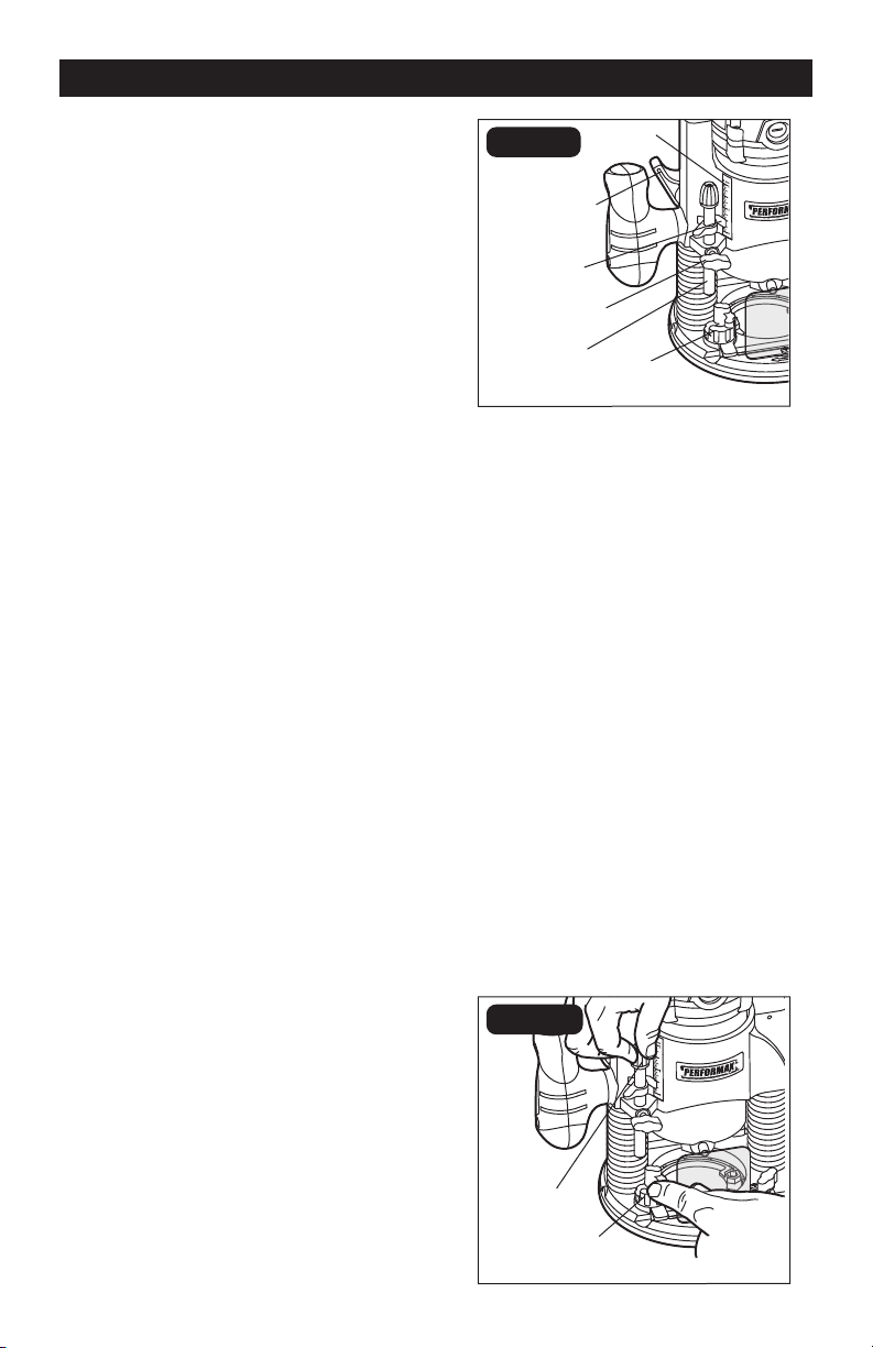
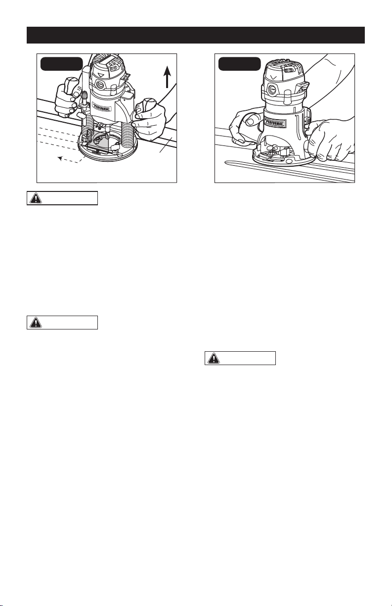
INTERNAL ROUTING WITH
PLUNGE BASE (FIG. 22)
1. With the depth-of-cut set, and the
plunge action locked in the raised (Up)
position place the sub-base flat on the
workpiece.
2. Turnurn the motor “ON” and let the
motor build up to its full selected speed
(FIG. 22).
3. To begin your cut, unlock the plunge-
lock lever and gently lower the plunge
action evenly into the workpiece.
4. When the desired depth-of-cut is
achieved, lock the plunge-lock lever
(Down) and proceed to make your cut.
5. When the cut is completed, turn the
motor “OFF” and let the cutter bit come
to a complete stop.
6. When the cutter bit comes to a complete
stop, unlock the plunge-lock lever (Up)
and the plunge action will automatically
retract the cutter bit from workpiece.
WARNING:
Removing the cutter bit
from the workpiece while it is still rotating
could damage the workpiece and result in
loss of control, causing serious personal
injury.
7. Unplug the router from the power source,
place the router on worktable, and
inspect the finished cut in the workpiece.
OPERATION
Page 20
FIG. 22
Edge
guide
Feed
direction
Plunge
up
WARNING:
Always securely clamp
the workpiece in place, and keep a rm
grip on the router base with both hands at
all times. Failure to do so could result in
loss of control, causing serious personal
injury.
FREEHAND ROUTING WITH THE
FIXED BASE (FIG. 23)
WARNING:
Do not use large
cutter bits for freehand routing. Using
large cutter bits when freehand routing
could cause loss of control or create other
hazardous conditions that could result
in personal injury. If using a router table,
large bits should be used for edging only.
When used freehand, the router becomes
a flexible and versatile tool. This flexibility
makes it possible to easily rout signs, relief
sculptures, etc.
When freehand routing:
1. Draw or lay out the pattern on the
workpiece.
2. Choose the appropriate bit.
3. Follow the instructions for INTERNAL
ROUTING, and rout the pattern in two or
more passes. Do not exceed 1/8” depth
of cut in a single pass. This will help
provide better control, as well as serve
as a guide on the next passes.
FIG. 23
NOTICE: A core-box bit or V-groove
bit is often used for routing letters and
engraving objects. Straight bits and
ball mills are often used to make relief
carvings. Veining bits are used to carve
small, intricate details.
NOTICE: Making a single deep cut is
never advisable. Smaller-diameter bits are
easily broken by too much side thrust and
torque. Larger bits will cause a rough cut
and be difcult to guide and control. For
these reasons, do not exceed 1/8” depth
of cut in a single pass.
WARNING:
Always securely clamp
your workpiece in place, and keep a rm
grip on the router base with both hands at
all times. Failure to do so could result in
loss of control causing possible serious
personal injury.
OPERATION
Page 21
EDGING WITH A PILOT
BIT (FIG. 24-25)
Arbor-type bits with pilots are excellent for
edge shaping of any workpiece edge that
is either straight or curved at a curvature
as great as or greater than the radius of the
bit to be used. The pilot prevents the bit
from making an excessively deep cut; and
holding the pilot firmly in contact with the
workpiece edge throughout prevents the cut
from becoming too shallow.
FIG. 24
Motor housing
Spindle lock
Cutter bit
Pilot
Fixed base
sub-base
Work piece
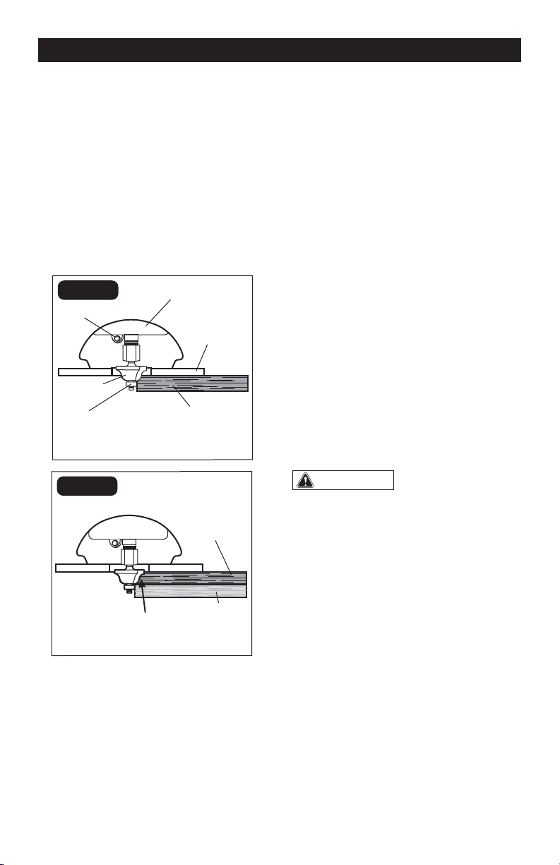
TOP EDGE SHAPING
FIG. 25
Work piece
Guide board
Whole edge of workpiece
WHOLE EDGE SHAPING
TOP EDGE SHAPING (FIG. 24)
Whenever the workpiece thickness, together
with the desired depth of cut (as adjusted by
the cutting-depth setting) are such that only the
top part of the edge is to be shaped (leaving at
least a 1/16”. thick uncut portion at the bottom),
the pilot can ride against the uncut portion,
which serves to guide it (FIG. 24).
WHOLE EDGE SHAPING (FIG. 25)
If the workpiece is too thin or the bit is set so
low that there will be no uncut edge against
which to ride the pilot, an extra board must
be placed under the workpiece to act as
a guide (FIG. 25). This “guide” board must
have exactly the same contour - straight
or curved - as the workpiece edge. If it is
positioned so that its edge is flush with the
workpiece edge, the bit will make a full cut
(in as far as the bit radius). On the other
hand, if the guide is positioned so that it
extends beyond the edge of the workpiece),
the bit will make less than a full cut - which
will alter the shape of the finished edge.
NOTICE: The size (diameter) of the pilot
that is used determines the maximum
cut width that can be made with the pilot
against the workpiece edge. (The small
pilot exposes the entire bit; the large one
reduces this amount by 1/16”.) Any of the
piloted cutter bits can be used without a
pilot for edge shaping with guides.
WARNING:
Always securely clamp
your workpiece and keep a rm grip on
the router base with both hands at all
times. Failure to do so could result in
loss of control causing possible serious
personal injury.
OPERATION
Page 22
FEEDING THE ROUTER (FIG. 26)
The secrets to professional routing are a
careful set-up for the cut, selecting the
proper depth of cut, knowing how the cutter
bit reacts in your workpiece, and the rate
and direction of feed of the router.
FIG. 26
Router feed direction
Router feed
direction
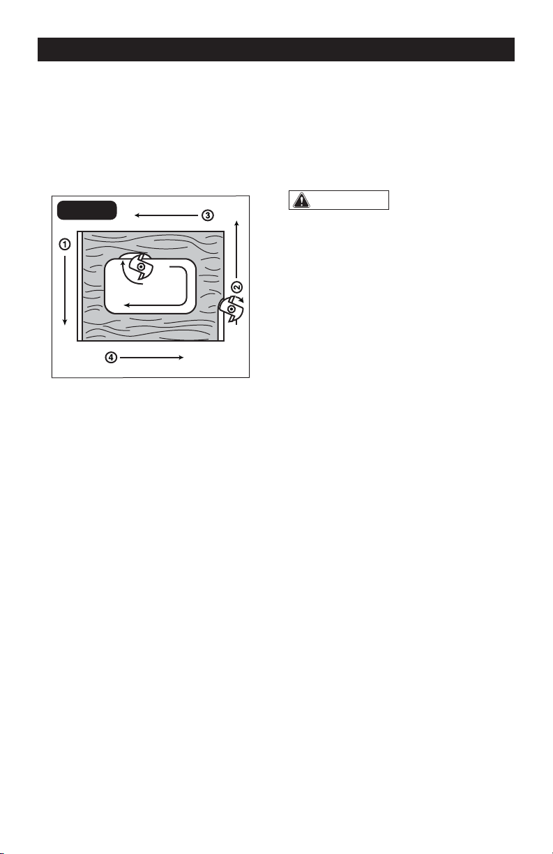
DIRECTION OF FEED -
EXTERNAL CUTS (FIG. 26)
The cutter bit rotates clockwise. Feeding the
bit from left to right will cause the bit to pull
the router towards the workpiece (FIG. 26).
If the router is fed in the opposite direction
(right to left), the rotating force of the cutter
bit will tend to throw the bit away from the
workpiece.
This is called “Climb-Cutting”. “Climb-
Cutting” may cause loss of control, possibly
resulting in personal injury. When “Climb-
Cutting” is required (e.g. backing around
a corner), exercise extreme caution to
maintain control of the router. The high
speed of the cutter bit during a proper
feeding operation (left to right), results in
very little kickback under normal conditions.
However, if the cutter bit strikes a knot,
an area of hard grain, or a foreign object,
“Kickback” may result. Kickback may
damage your workpiece and could cause
you to lose control of the router, possibly
causing personal injury. Kickback is always
in the opposite direction of the clockwise
cutter bit rotation, or counterclockwise. To
guard against and help prevent Kickback,
plan your set-up and direction of feed so
that you’re always keeping the sharp edges
of the cutter bit biting straight into uncut
wood. Always inspect your workpiece for
knots, hard grain, and foreign objects.
WARNING:
Kickback causes the
power tool to jerk back toward the user,
causing possible loss of control and
serious injury. Always take precautions
against kickback as described in the
operator’s manual.
KICKBACK
Because of the high speed of the cutting
bit during a proper feeding operation (left
to right), there is very little kickback under
normal conditions. However, if the cutting
bit strikes a knot, an area of hard grain in
the workpiece, or a foreign object, the
normal cutting action could be affected
and cause “Kickback.” This Kickback may
cause damage to your workpiece, and could
cause you to lose control of the router,
possibly causing serious personal injury.
Kickback is always counterclockwise: the
opposite direction of the clockwise cutting
bit rotation.
To guard against and help prevent Kickback,
Always inspect the workpiece for knots,
hard grain, and foreign objects that could
cause a kickback problem and plan the set-
up and direction of feed so that the router is
always moving, and keep the sharp edges
of the cutting bit continuously biting straight
into new (uncut) wood (workpiece).
OPERATION
Page 23
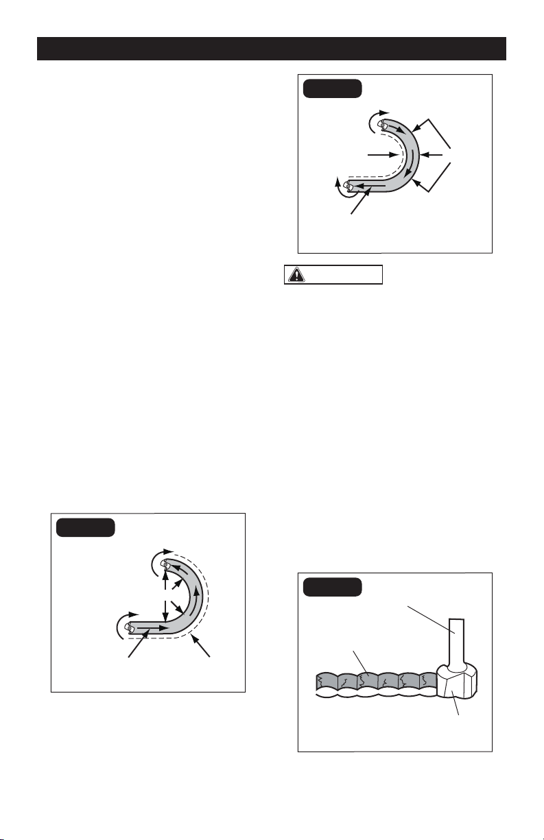
DIRECTION OF FEED – INTERNAL
CUTS (FIG. 27-28)
When making an internal cut, such as a
groove, dado, or slot, always try to have the
guide you are using with the router (edge
guide, straight edge, board guide), on the
right-hand side of the router as you make
the cut (FIG. 27).
When the guide is positioned on the
right hand side of the router, the router
travel should be from left to right and
“counterclockwise” around curves (FIG. 27).
This counterclockwise action around the
curve could cause “Climb cutting”. Always
be alert and exercise extreme caution to
maintain control of the router when making
this type of cut around curves.
When the guide is positioned as shown in
FIG. 28, the router travel should be from left
to right and clockwise around curves.
If there is a choice, the set-up in FIG. 28
is easier to use, but there is the possibility
of “Climb Cutting” around curves. In either
case, FIG. 27 or FIG. 28, the sideways thrust
of the router cutting is always against the
guide, as is proper.
FIG. 27
GUIDE OUTSIDE
BIT
ROTATION
BIT
ROTATION
ROUTER FEED
DIRECTION
GUIDE
THRUST
FIG. 28
GUIDE INSIDE
BIT
ROTATION
BIT
ROTATION
ROUTER FEED
DIRECTION
GUIDE
THRUST
WARNING:
Always securely clamp
the workpiece in place, and keep a rm
grip on the router base with both hands at
all times. Failure to do so could result in
loss of control causing possible serious
personal injury.
RATE OF FEED (FIG. 29-30)
The proper rate of feed depends on several
factors: the hardness and moisture content
of the workpiece, the depth of cut, and the
cutting diameter of the bit.
When cutting shallow grooves in soft woods,
such as pine, you may use a faster rate of
feed. When making deep cuts in hardwoods,
such as oak, you should use a slower rate
of feed.
FIG. 29
Bit shank
Cut
Cutter
TOO FAST
OPERATION
Page 24
FEEDING TOO RAPIDLY (FIG. 29)
Clean and smooth finished cuts can only
be achieved when the cutting bit is rotating
at a relatively high speed, taking very small
bites, and producing tiny, clean-cut chips.
Forcing the feed of the cutting bit forward
too rapidly slows the revolution of the
cutting bit, and the bit takes larger bites as it
rotates. Larger bites mean larger chips and
a rough finish. This forcing action can also
cause the router motor to overheat.
Under extreme force-feeding conditions,
the revolutions can become so slow and
the bites become so large that chips are
only partially cut off, causing splintering and
gouging of the workpiece.
The router will make clean, smooth cuts if it
is allowed to run freely without the overload
of forced feeding. You can detect forced
feeding by the sound of the motor. Its usual
high-pitched whine will sound lower and
louder as it loses speed. Holding the router
against the workpiece will also be more
difficult to do.
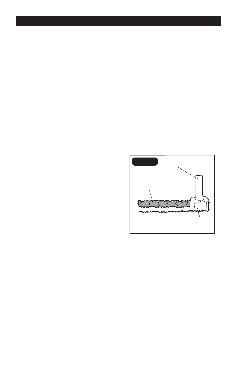
FEEDING TOO SLOWLY (FIG. 30)
When you feed the cutting bit too slowly, the
rotating cutting bit does not cut into new
wood rapidly enough to take a bite. Instead,
it scrapes away sawdust-like particles. This
scraping produces heat, which can glaze,
burn, and mar the cut in the workpiece and,
in extreme cases, overheat the cutting bit.
When the cutting bit is scraping instead of
cutting, the router is more difficult to control
as you feed it.
With almost no load on the motor, the
cutting bit has a tendency to bounce off the
sides of the cut in the workpiece, producing
a cut with a rippled finish instead of clean,
straight sides.
FIG. 30
Bit shank
Cut
Cutter
TOO SLOW
OPERATION
Page 25
Before cleaning or performing any
maintenance, verify that the router has been
disconnected from the power supply. Keep
all ventilation openings clean. Avoid using
solvents when cleaning plastic parts. Most
plastics are susceptible to damage from
various types of commercial solvents. Use
a clean cloth to remove dirt, oil, and grease.
If the supply cord is damaged, it must
be replaced by a specially prepared cord
available through the service organization.
WARNING:
Do not let brake uids,
gasoline, petroleum-based products,
penetrating oil, etc. come into contact
with plastic parts. They contain chemicals
that can damage, weaken, or destroy
plastic.
WARNING:
To ensure safety and
reliability, all repairs should be performed
by a qualied service technician.
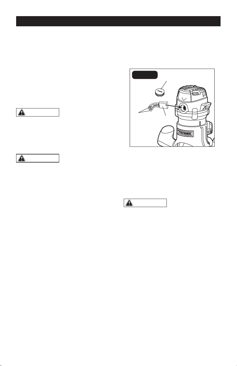
REPLACEMENT OF CARBON
BRUSHES (FIG. 31)
1. Disconnect the plug from the power
supply.
2. Replace both carbon brushes when
either has less than 1/4-in. length of
carbon remaining, or if the spring or wire
is damaged or burned.
3. Using a slotted screwdriver, remove
the black, plastic cap on each side of
the router motor (FIG. 31) and carefully
withdraw the spring-loaded brush
assemblies. Keep brushes clean and
sliding freely in their guide channels.
NOTICE: To reinstall the same brushes,
make sure that the brushes go back in the
same way they came out. This will avoid
the need for a break-in period.
4. Insert new brush assemblies into the
guide channels with the carbon part
going in first, being certain to fit the
two metal “ears” into their slots in the
channel (FIG. 31).
FIG. 31
Cap
Brushes
Ears
5. Remember to replace both end caps
after inspecting or servicing brushes.
Tighten the caps snugly, but do not over-
tighten. The router should be allowed to
“run in” (run at no load without a cutter
bit) for 5 minutes before use, to seat the
new brushes properly.
WARNING:
For your safety, always
turn off the switch and unplug the router
motor from the power source before
performing any maintenance or cleaning.
MAINTENANCE

Page 26
TROUBLESHOOTING
PROBLEM CAUSE SOLUTION
The router does not work.
Plug is not plugged into the
power source.
Plug the detachable cord
into the power source.
Switch is in “OFF” position.
Pull the switch to “ON”
position.
The carbon brushes have
worn out completely.
Remove the brush caps,
and replace the old brushes
with new ones.
The surface of the
workpiece is not smooth
after cutting.
The bit is dull. Change to a sharp bit.
Routing at an inappropriate
bit speed.
Select an appropriate bit
speed.
Bit cannot be installed.
Bit size is inappropriate for
the collet/nut.
Use only 1/4” diameter bits
with the 1/4” collet; use
only 1/2” diameter bits with
the 1/2” collet.

Page 27
NOTES

Page 28
NOTES

Page 29
NOTES

Page 30
SAVE YOUR RECEIPTS
THIS WARRANTY IS VOID WITHOUT THEM
30-DAY MONEY BACK GUARANTEE:
This PERFORMAX
®
brand power tool carries our 30-Day Money Back Guarantee. If
you are not completely satisfied with your PERFORMAX
®
brand power tool for any
reason within thirty (30) days from the date of purchase, return the tool with your
original receipt to any MENARDS
®
retail store, and we will provide you a refund – no
questions asked.
2-YEAR LIMITED WARRANTY:
This PERFORMAX
®
brand power tool carries a 2-Year Limited Warranty to the original
purchaser. If, during normal use, this PERFORMAX® power tool breaks or fails due
to a defect in material or workmanship within two (2) years from the date of original
purchase, simply bring this tool with the original sales receipt back to your nearest
MENARDS
®
retail store. At its discretion, PERFORMAX
®
agrees to have the tool or
any defective part(s) repaired or replaced with the same or similar PERFORMAX®
product or part free of charge, within the stated warranty period, when returned by
the original purchaser with original sales receipt. Notwithstanding the foregoing,
this limited warranty does not cover any damage that has resulted from abuse or
misuse of the Merchandise. This warranty: (1) excludes expendable parts including
but not limited to blades, brushes, belts, bits, light bulbs, and/or batteries; (2) shall
be void if this tool is used for commercial and/or rental purposes; and (3) does not
cover any losses, injuries to persons/property or costs. This warranty does give
you specific legal rights and you may have other rights, which vary from state to
state. Be careful, tools are dangerous if improperly used or maintained. Seller’s
employees are not qualified to advise you on the use of this Merchandise. Any oral
representation(s) made will not be binding on seller or its employees. The rights
under this limited warranty are to the original purchaser of the Merchandise and
may not be transferred to any subsequent owner. This limited warranty is in lieu
of all warranties, expressed or implied including warranties or merchantability and
fitness for a particular purpose. Seller shall not be liable for any special, incidental,
or consequential damages. The sole exclusive remedy against the seller will be for
the replacement of any defects as provided herein, as long as the seller is willing or
able to replace this product or is willing to refund the purchase price as provided
above. For insurance purposes, seller is not allowed to demonstrate any of these
power tools for you.
For questions / comments, technical assistance or repair parts –
Please Call Toll Free at: 1-866-858-2664 (M-F 8:30am-5:00pm Est.)
Router Combo Kit
WARRANTY

04/2016
© 2016 Menard, Inc., Eau Claire, WI 54703