

OPERATING MANUAL
10 Amp Plunge Base Router
241-0974
IMPORTANT :
Read this Operating Manual carefully before using this tool. Pay close
attention to all Safety Instructions, Warnings, and Caution sections. Use this
tool properly and only for its intended use
Safety symbols in this manual are used to indicate possible dangers, and
the explanations must be understood completely. The safety warnings do not
eliminate any danger by themselves, and they are not a substitute for proper
accident prevention measures.
This Safety Alert Symbol indicates caution, warning, or danger. Failure to
obey a safety warning may result in serious injury to the operator or to others.
To reduce the risk of injury, fire, or electric shock, follow the safety precau-
tions closely.

2
TABLE OF CONTENTS
Specification……………..…………………………..………..…..……Page 2
Rules for Safe Operation…………………………………………….…Page 3
Operation..………..………..………..………..………..………..………Page 8
Accessories..………..………..………..………..………..………...… Page 16
Maintenance..………..………..………..………..………..………..…Page 16
Exploded view and part list.............................................................................Page17
Warranty..………..………..………..………..………..………..…...…Page 20
SPECIFICATIONS
Motor: 120 V 60 Hz 10 A
Horsepower: 1 3/4 HP
Speed: 11000–28000 RPM (no load)
Collet capacity: 1/4”
Plunge stroke: 2 1/8” (55 mm)
Base imension: 6 1/2” (165 mm)
Micro-fine depth: Adjusts to 1/64”
Depth stop: 4-stage turret stop
Weight: 7 lb 11 oz (3.5 kg)

3
RULES FOR SAFE OPERATION
KNOW THE TOOL
Carefully read this operating manual and all labels affixed to the sander
before using this tool. Keep this manual available for future reference.
IMPORTANT
This tool should only be serviced by a qualified service technician. For more
information, call the toll free helpline at 1-866-858-2664
READ ALL INSTRUCTIONS THOROUGHLY
GENERAL SAFETY RULES FOR POWER TOOLS
WARNING: To reduce the risk of injury, the user must read the Owner’s
Manual.
WARNING: Read all safety warnings and instructions. Failure to follow
the warnings and instructions may result in electric shock, re and/or seri-
ous injury.
SAVE ALL WARNINGS AND INSTRUCTIONS FOR FUTURE
REFERENCE.
The term “power tool” in the warnings refers to your AC-powered (corded)
power tool or battery-powered (cordless) power tool.
WORK AREA SAFETY
Keep work area clean and well lit. Cluttered or dark areas invite accidents .
Do not operate power tools in an explosive environment, such as in the
presence of ammable liquids, gases or dust. Power tools create sparks
that may ignite the dust or fumes .
Keep children and bystanders away while
operating a power tool. Distractions can cause
you to lose control.
ELECTRICAL SAFETY
The piug on the power tool must match the outlet.
Never modify the plug in any way. Do not use
adaptor plugs with earthed (grounded) power
tools. Unmodified plugs and matching outlets will
reduce the risk of electric shock .
120V ~ 60Hz

4
Avoid body contact with earthed or grounded surfaces such as pipes,
radiators, ranges and refrigerators. There is an increased risk of electric
shock if your body is earthed or grounded.
Do not expose power tools to rain or wet conditions. Water entering a
power tool will increase the risk of electric shock .
Do not abuse the cord. Never use the cord for carrying, pulling or
unplugging the power tool. Keep the cord away from heat, oil. sharp
edges or moving parts. Damaged or entangled cords increase the risk of
electric shock .
When operating a power tool outdoors, use an extension cord that is
suitable for outdoor use. The use of a cord that is suitable for outdoor use
reduces the risk of electric shock .
If operating a power tool in a damp location is unavoidable, use a power
supply that is protected by a ground fault circuit interrupter (GFCI). The
use of an GFCI reduces the risk of electric shock.
PERSONAL SAFETY
Stay alert, watch what you are doing, and use common sense when
operating a power tool. Do not use a tool while tired or under the
inuence of drugs, alcohol. or medication. A moment of inattention while
operating a power tool may result in serious personal injury .
Use personal protective equipment. Always wear eye protection.
Protective equipment such as a dust mask, non-skid safety shoes, a hard
hat, or hearing protection, used for appropriate conditions, will reduce
personal injuries .
Prevent unintentional starting. Ensure that the switch is in the off position
before connecting to a power source and/or battery pack, picking up or
carrying the tool. Carrying power tools with your finger on the switch or
energizing power tools that have the switch on invites accidents .
Remove any adjusting keys or wrenches before turning the power tool
on. A wrench or a key left attached to a rotating part of the power tool
may result in personal injury .
Do not overreach. Keep proper footing and balance at all times. This
enables better control of the power tool in unexpected situations .
Dress properly. Do not wear loose clothing or jewelry. Keep your hair,
clothing and gloves away from moving parts. Loose clothes, jewelry or
long hair can get caught in moving parts .

5
If devices are provided for the connection of dust extraction and
collection facilities, ensure these are connected and properly used. Use
of these devices can reduce dust-related hazards.
USE AND CARE OF THE POWER TOOLS
Do not force the power tool. Use the correct power tool for your
application. The correct power tool will do the job better and more safely
when used at the rate at which it was designed to work .
Do not use the power tool if the switch does not turn it on and off. Any
power tool that cannot be controlled with the switch is dangerous and
must be repaired .
Disconnect the plug from the power source and/or disconnect the battery
pack from the power tool before making any adjustments, changing
accessories, or storing the power tool. Such preventive safety measures
reduce the risk of starting the power tool accidentally .
Store idle power tools out of the reach of children and do not allow
persons who are unfamiliar with the power tool or these instructions
to operate the power tool. Power tools are dangerous in the hands of
untrained users .
Maintain power tools. Check for misalignment or binding of moving
parts, broken parts, and any other condition that may affect the power
tool’s operation. If damaged, have the power tool repaired before use.
Many accidents are caused by poorly maintained power tools .
Keep cutting tools sharp and clean. Properly maintained cutting tools with
sharp cutting edges are less likely to bind, and are easier to control.
Use the power tool. accessories and tool bits etc. in accordance with
these instructions, taking into account the working conditions and the
work to be performed. Using the power tool for operations different from
those for which it is intended could result in a hazardous situation.
SERVICE
Have your power tool serviced by a qualied repair person using only
identical replacement parts. This will ensure that the safety of the power
tool is maintained.

6
SPECIFIC SAFETY INSTRUCTIONS FOR THE PLUNGE ROUTER
WARNING: Read all instructions. Failure to comply with all of the follow-
ing instructions may result in electric shock, fire and/or serious injury.
• Hold the power tool by its insulated grips when performing any operation
in which the cutting tool may come into contact with concealed wiring
or its own cord. Contact with a “live” wire will also make exposed metal
parts of the tool “live” and subject the operator to electric shock.
• Use clamps or another practical means of securing and supporting the
workpiece to a stable platform. Holding the work by hand or against your
body leaves it unstable and may result in loss of control.
• Keep the handles dry, clean, and free of oil or grease. This will permit
better control of the tool.
• Keep hands away from cutting area. Never place your hands beneath the
workpiece for any reason. Keep the base of the router in rm contact with
the workpiece when cutting. Grip the router only by its handles. These
precautions will reduce the risk of personal injury.
• Use sharp bits. Dull bits may cause the router to swerve or stall under
pressure.
• Never touch the bit immediately after use. It may be extremely hot.
• Be sure that the motor has completely stopped before you put the router
down. Injury or damage could result from a head that is still spinning when
the tool is laid down.
• Be sure that the router bit is clear of the workpiece before starting the
motor. If the bit is in contact with the workpiece when the motor starts, the
router could jump, resulting in damage or injury.
• Only use router bits with a shank diameter equal to the size of the tool’s
collet.
• Only use router bits suitable for the tool’s no-load speed.
• Make sure the collet nut is securely tightened to prevent the router bit
from slipping during use.
• Avoid prolonged contact with dust from power sanding, sawing, grinding,
drilling, and other construction activities. Wear protective clothing and
wash exposed areas with soap and water. Allowing dust to get into your
mouth, eyes or remain on your skin may promote absorption of harmful
chemicals.

7
WARNING: Use of this tool can generate and/or disperse dust, which may
cause serious and permanent respiratory or other injuries. Always use the ap-
propriate certified respiratory device to protect against dust exposure. Direct
particles away from face and body.
CAUTION: Wear an appropriate personal hearing protective device dur-
ing use. Noise caused by this product could contribute to hearing loss under
certain conditions and periods of use.
8
OPERATION
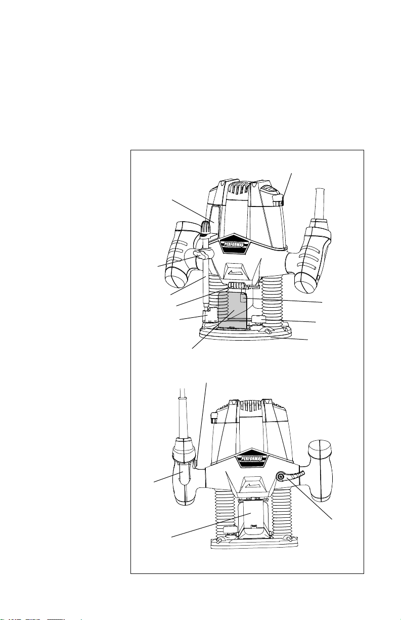
KNOW YOUR ROUTER (see Fig. 1)
Before attempting to use this plunge router, familiarize yourself with all
its operating features and safety requirements. The plunge router is only
designed to be used for straight and grooved milling and the forming of edges
in wood or similar materials. Any other uses of the router not described in
this manual could damage the tool or seriously injure the operator and are
therefore expressly excluded from approved applications.
1. Trigger switch
2. Lock-on button
3. Speed adjuster
4. Plunge lock lever
5. Spindle lock
6. Collet nut
7. Depth stop turret
8. Depth stop bar
9. Depth of cut scale
10. Dust extraction
adaptor
11. Chip shield
12. Locking screw
13. Lock bolt
14. Base plate
Fig. 1
9
3
6
13
14
11
2
1
10
4
7
5
8
12
9
WARNING: To prevent personal injury, always disconnect the plug from
the power source before assembly, adjustment or changing of bits. Failure to
comply with these instructions could result in accidental start-up and possible
injury.
WARNING: To reduce the risk of injury, do not overload the tool. Let it work
at its own pace. Guide the cord carefully to avoid accidentally cutting it.
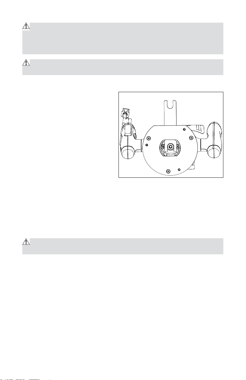
INSTALLING/REMOVING THE ROUTER BIT (see Fig. 2)
To install the bit
• Unplug the router.
• Remove the detachable chip
shield (11).
• Keep the spindle lock (5)
depressed and rotate the spindle
until the spindle lock fully
engages.
• Place the router upside down on
a smooth, flat surface.
• Loosen the collet nut (6) using the spanner wrench provided. Insert the
shank of the router bit into the collet.
• Keep the spindle lock button (5) depressed and tighten the collet nut (6)
using the spanner wrench provided.
• Release the spindle lock.
To remove the bit
CAUTION: Burn hazard. The router bits get hot during use. Allow sufficient
time for the bit to cool before replacing it.
• Keep the spindle lock button (5) depressed.
• Loosen the collet nut (6) using the spanner wrench provided and remove
the bit.
• Release the spindle lock.
Fig. 2

10
ADJUSTING THE DEPTH OF CUT (see Fig. 3)
WARNING: Turn the router off and disconnect it from the power supply.
The depth of cut is the distance
between the depth stop bar (8) and
the depth stop turret (7). The depth
of cut can be set in two different
ways as follows:
ADJUSTING THE DEPTH OF CUT
USING THE SCALE
• Unplug the router.
• Loosen the locking screw (12).
• Pull the plunge lock lever (4) up.
• Lower the router until the router bit touches the workpiece.
• Push the plunge lock lever (4) down.
• Move the pointer to the zero position on the scale (9).
• Add the desired depth of cut to the starting position.
• Move the depth stop bar (8) to the calculated position on the scale.
• Tighten the locking screw (12).
• Fine adjust using the adjusting knob.
• Pull the plunge lock lever (4) up and let the router return to its original
position.
• Switch the router on, then lower the unit to make the desired cut.
ADJUSTING THE DEPTH OF CUT USING A PIECE OF WOOD
• Unplug the router.
• Lower the router as described above.
• Pull the depth stop bar (8) up.
• Between the depth stop turret (7) and the depth stop bar (8), place a piece
of wood with a thickness equal to the desired depth of cut.
• Tighten the locking screw (12).
• Fine adjust using the adjusting knob (21).
• Remove the piece of wood.
• Pull the plunge lock lever (4) up and let the router return to its original
position.
• After switching the router on, lower it to make the desired cut.
Fig. 3
Adjusting Knob
Pointer
11
ADJUSTING THE DEPTH-STOP TURRET
If you want to make several cuts with a different depth, adjust each depth stop.
• Unplug the router.
• Loosen the locking screw.
• Set the depth stop turret to the desired setting. Turn clockwise or counter-
clockwise to lower or raise the depth stop turret.
• Tighten the locking screw.
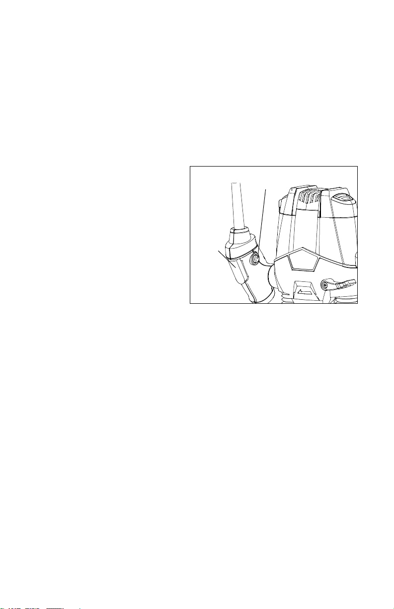
SWITCHING THE ROUTER ON AND OFF (see Fig. 4)
Switching the router on
Press the trigger switch (1).
Switching the router off
Release the trigger switch.
Continuous operation
To lock the trigger switch on for
continuous operation, squeeze the
trigger switch (1) and hold it while
depressing the lock-on button (2).
Hold the button while you release
the trigger switch; the tool will continue to run. Squeeze and release the
trigger switch to turn the tool off.
ELECTRONIC SPEED ADJUSTER
The speed of your router is variable (6 variable speeds). Use the electronic
speed adjuster (3) to produce uniform results in wood, plastics. Use lower
settings for large diameter bits and higher settings for small diameter bits.
USING THE ROUTER
• Make sure that the material to be cut is securely clamped and provides
sufficient stability to support the router while it is operating.
• To control the router, keep both hands on the grips.
• Rotate the router counter-clockwise when cutting outside edges. Rotate it
clockwise when cutting inside edges.
• Always hold the router from the front, ensuring that the chip shield is
between yourself and the bit.
• After setting the cutting depth as described, position the router so that
the bit is directly above the point you plan to cut. With the router running,
lower the unit smoothly into the workpiece. (DO NOT FORCE THE ROUTER
DOWN.) When the tool reaches its pre-set depth, tighten the plunge
Fig. 4
Trigger
Switch
Lock-on Button

12
release lever. Once you have finished routing, loosen the plunge release
lever and allow the spring to lift the router directly out of the workpiece.
NOTE: Always feed the workpiece to the router against the direction of the
bit’s rotation.
FEED SPEED AND RATE OF CUT
Feed rate depends on the material and bit configuration. Experience is the
best guide. Become familiar with the sound and feel of the router by making
practice cuts on scrap materials. Perform a preliminary adjustment of the
speed control, selecting a higher speed for smaller diameter bits and a lower
speed for larger diameter bits.
The router bit rotates at a very high speed and may heat up, causing burn
marks if the router is moved too slowly through the wood. Feeding the
router too quickly or trying to remove too much material in a single pass will
overload the motor. Use two or more passes for extra-large cuts, especially
in the case of hardwood.
DUST EXTRACTION ADAPTOR
When employing the dust extraction adaptor, be sure the vacuum cleaner
is out of the way and properly secured so that it will not tip over or interfere
with the router or workpiece. The vacuum hose and power cord must also
be positioned so that they do not interfere with the router or workpiece. If the
vacuum cleaner or vacuum hose cannot be positioned properly, it should be
removed.
• Turn on the vacuum cleaner before turning on the router.
• Empty the vacuum cleaner as necessary.
Straight edge guide for the router (see Fig. 5)
The straight edge guide is an effective aid to cutting a straight line when
chamfering or grooving.
• Loosen the lock bolts.
• Feed the bars on the edge guide
through the holes in the base plate.
• Adjust the distance between the
router bit and the edge guide
by moving the guide until it is
situated at the proper distance.
• Tighten the lock bolts to hold the
straight edge guide in position.
Fig. 5

13
TIPS FOR OPTIMAL USE
• Rotate the tool counter-clockwise when working on outer edges. Rotate
the tool clockwise when working on inner edges.
• Use HSS (high speed steel) router bits for softwood.
• Use TCT (tungsten carbide tipped) router bits for hardwood.
• No guide is required for use of the tool. This is useful for writing signs and
performing creative work. Only make shallow cuts.
• Refer to the following table for common types of router bits.
ROUTER ACCESSORIES
Use either a bit with a shank-mounted bearing or a bit with a bushing to work
with templates, patterns, fixtures, and other router accessories. Using the bit
and bushing combination has the advantage of allowing the user to control
the depth of cut.
ROUTER BUSHINGS
The bushing rides against the template to allow the user to accurately
replicate an infinite variety of shapes and cuts, such as:
• Shaped pieces
• Recesses for inlays
• Holes
• Straight edges
• Rabbets and other grooves parallel to the edge of the template
Match the router bushing to the cutting diameter of your bit and the offset
from the template that works best for your project.
Use router bushings with the ¼” straight bit, or with any cutting bit that:
• Does not have a shank-mounted bearing
• Has a cutting-head diameter that will pass through the bushing opening.
14
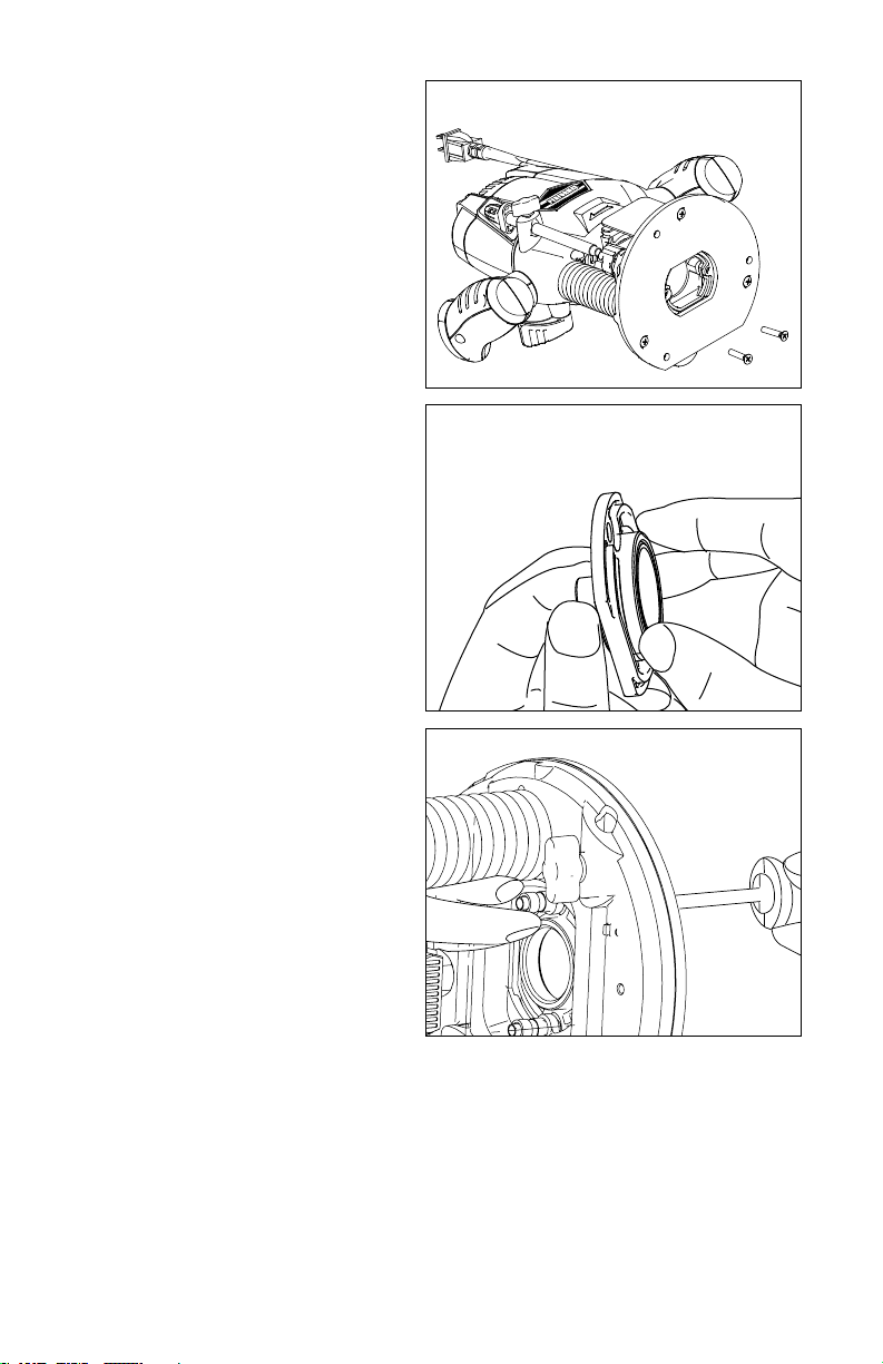
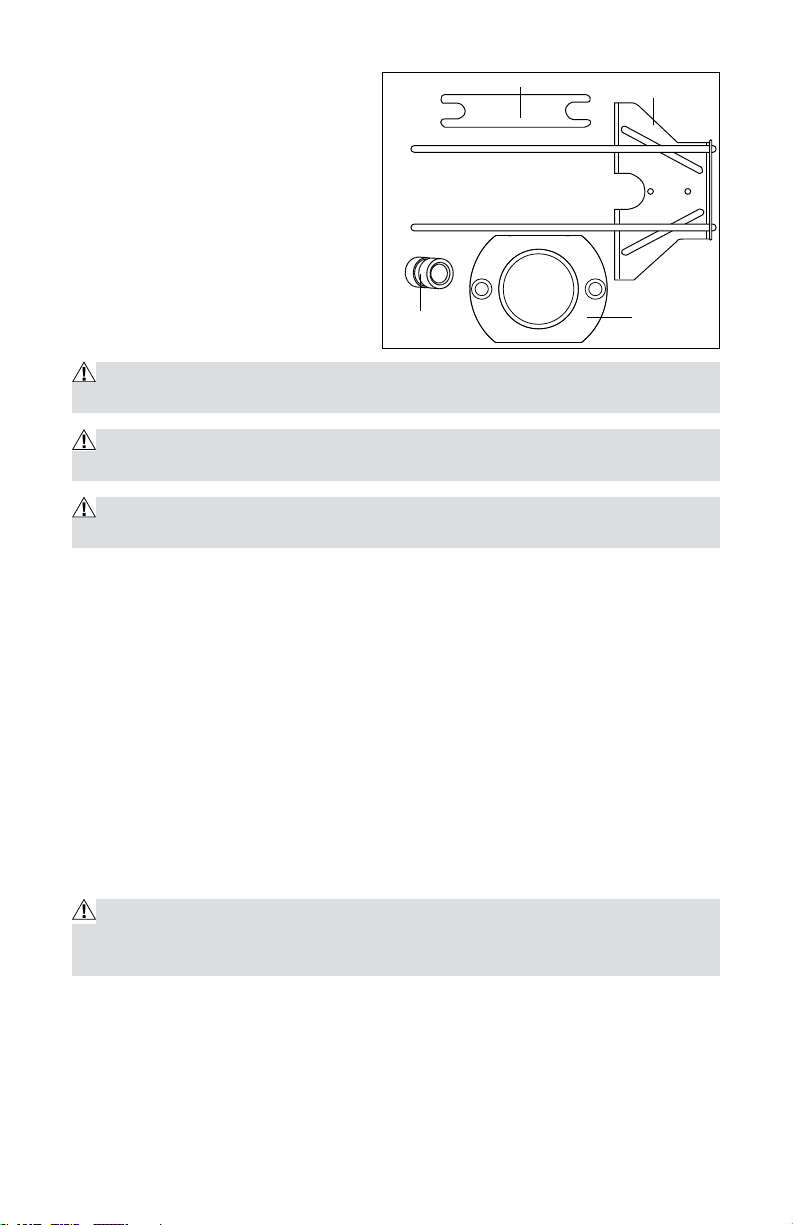
To install bushing (sold separately):
1. Unplug the router.
2. Remove two screws from router
base,and then remove the dust
extraction adapter from the
router.
3. Put the bushing into the center
hole of the adapter(included),
and screw in the bushing ring to
secure it. (Fig.7)
4. Use the two screws removed
in STEP 2 to attach the adapter
with the bushing to the router
base, and tighten the column nut
(included) with the screw. (Fig.8)
Fig. 6
Fig. 7
Fig. 8
15
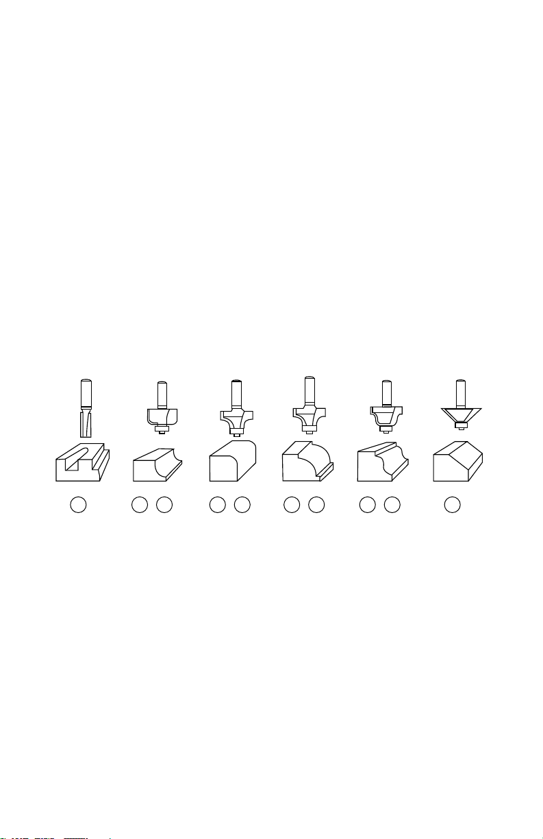
ROUTER BITS (not included)
The following router bit (not included) are recommend use with this router.
1. 1/4” Diameter Straight cutting bit
2. 1/4” Radius Cove Bit
3. 1/4” Radius Round Over Bit
4. 3/8” Radius Bead Bit
5. 1/4” Diameter Roman Ogee Bit
6. 45
o
Chamfer Bit 1 1/2”
7. 1/2” Radius Cove Bit
8. 1/2” Radius Round Over Bit
9. 1/2” Radius Bead Bit
10. 1/2” Diameter Roman Ogee Bit
1 2 3 4 5 67 8 9 10
16
ACCESSORIES
(see Fig. 9)
1. Collet wrench
2. Straight edge guide
3. Adapter
4. Column nut 2 pcs
MAINTENANCE
WARNING: To ensure safety and reliability, all repairs should be performed
by a qualified service technician.
WARNING: When servicing, use only identical replacement parts. The use
of any other parts may create a hazard or cause damage to the product.
WARNING: Unplug the impact wrench from the power source before clean-
ing or performing any maintenance.
If the supply cord is damaged, it must be replaced by a specially prepared
cord available through the service organization.
Before each use:
· Inspect the impact wrench, the switch, and the cord for damage.
· Check for damaged, missing, or worn parts.
· Check for loose screws, misalignment or binding of moving parts, or any
other condition that may affect the operation.
· If abnormal vibration or noise occurs, turn the impact wrench off
immediately, and have the problem corrected before further use.
Using compressed air may be the most effective cleaning method. Always
wear safety goggles when cleaning tools using compressed air.
WARNING: Do not allow brake fluids, gasoline, petroleum-based products,
penetrating oil, etc. to come into contact with plastic parts. These substances
contain chemicals that can damage, weaken, or destroy plastic.
Fig. 9
1
4
2
3
17
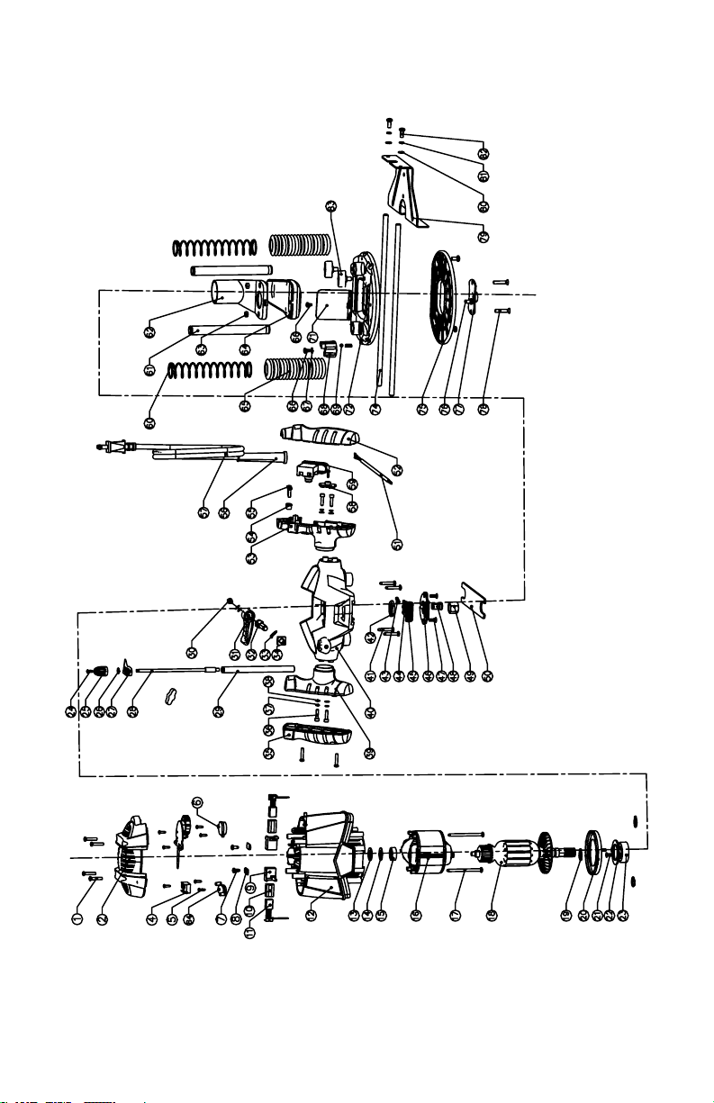
Exploded View

18
Parts List
No. Part Name Qty
1 Tapping Screw 8
2 Cover 1
3 N/A
4 Speed Adjuster 1
5 Tapping Screw 8
6 Cover 1
7 Tapping Screw 2
8 Epoxy Board 2
9 Brush Holder 2
10 Brush Bush 2
11 Carbon Brush 2
12 Motor Housing 1
13 Spring 1
14 Washer 1
15 Bearing 1
16 Stator 1
17 Tapping Screw 2
18 Rotor 1
19 Circlips For Shaft 3
20 Fan Baffle 1
21 Screw 2
22 Bearing Clamping Plate 1
23 Ball Bearing 1
24 Screw 1
25 Adjusting Knob 1
26 O Ring 1
27 Depth Indicator 1
28 Depth Adjusting Bolt 1
29 Depth Stop Bar 1
30 Screw 1
31 Plunge Lock Lever 1
32 Slotted Set Screw 1
33 Wave Washer 1
34 Nut 1
35 Left Handle Cover 1
36 Hexagon Socket Screw 4
37 Spring Washer 5
38 Plain Washer 5
39 Left Handle 1
40 Plunge Frame 1
41 Tapping Screw 4
42 Nut 1
43 Spring 2

19
44 Spindle Lock 1
45 Spindle Lock Button 1
46 Lock Cover 1
47 Thread Forming Screw 1
48 Collet 2
49 Lock Nut 1
50 Wrench 1
51 Inner Wire 1
52 Right Handle Cover 1
53 Right Handle 1
54 Cord Anchorage 1
55 Screw 2
56 Cord Guard 1
57 Power Cord & Plug 1
58 Cover 1
59 Switch 1
60 Spring 2
61 Plunge Rod 2
62 Upper Cover 1
63 Hexagon Nut 2
64 Lower Cover 1
65 Bellows Seal 2
66 Slotted Shoulder Screw 2
67 Waver Washer 1
68 Turntable 1
69 Steel Ball 1
70 N/A
71 Chip Shield 1
72 Bottom Support 1
73 N/A
74 Guiding Rod 2
75 Base Plate 1
76 Screw 3
77 Guide Bush 1
78 Screw 2
79 Parallel Guide 1
80 Plain Washer 2
81 Spring Washer 2
82 Screw 2
83 Lock Bolt 3
84 Cover 1

20
PERFORMAX
®
10 Amp Plunge Base Router WARRANTY
30-DAY MONEY BACK GUARANTEE:
This PERFORMAX
®
brand power tool carries our 30-Day Money Back
Guarantee. If you are not completely satisfied with your PERFORMAX
®
brand
power tool for any reason within thirty (30) days from the date of purchase,
return the tool with your original receipt to any MENARDS
®
retail store, and
we will provide you a refund – no questions asked.
2-YEAR LIMITED WARRANTY:
This PERFORMAX
®
brand power tool carries a 2-Year Limited Warranty
to the original purchaser. If, during normal use, this PERFORMAX
®
power
tool breaks or fails due to a defect in material or workmanship within two
(2) years from the date of original purchase, simply bring this tool with the
original sales receipt back to your nearest MENARDS
®
retail store. At its
discretion, PERFORMAX
®
agrees to have the tool or any defective part(s)
repaired or replaced with the same or similar PERFORMAX
®
product or
part free of charge, within the stated warranty period, when returned by the
original purchaser with original sales receipt. Not withstanding the foregoing,
this limited warranty does not cover any damage that has resulted from
abuse or misuse of the Merchandise. This warranty: (1) excludes expendable
parts including but not limited to blades, brushes, belts, bits, light bulbs, and/
or batteries; (2) shall be void if this tool is used for commercial and/or rental
purposes; and (3) does not cover any losses, injuries to persons/property or
costs. This warranty does give you specific legal rights and you may have
other rights, which vary from state to state. Be careful, tools are dangerous if
improperly used or maintained. Seller’s employees are not qualified to advise
you on the use of this Merchandise. Any oral representation(s) made will not
be binding on seller or its employees. The rights under this limited warranty
are to the original purchaser of the Merchandise and may not be transferred
to any subsequent owner. This limited warranty is in lieu of all warranties,
expressed or implied including warranties or merchantability and fitness for
a particular purpose. Seller shall not be liable for any special, incidental, or
consequential damages. The sole exclusive remedy against the seller will be
for the replacement of any defects as provided herein, as long as the seller
is willing or able to replace this product or is willing to refund the purchase
price as provided above. For insurance purposes, seller is not allowed to
demonstrate any of these power tools for you.
For questions / comments, technical assistance or repair parts –
Please Call Toll Free at: 1-866-858-2664 (M-F 8am – 6pm)
SAVE YOUR RECEIPTS. THIS WARRANTY IS VOID WITHOUT THEM.