INSTRUCTION MANUAL
MANUAL DE INSTRUCCIONES
Cordless Router
Rebajadora Inalámbrica
GPR01
IMPORTANT: Read Before Using.
IMPORTANTE: Lea antes de usar.
2 ENGLISH
ENGLISH (Original instructions)
SPECIFICATIONS
Model: GPR01
Collet chuck capacity 12 mm or 1/2"
Plunge capacity 0 - 60 mm (0 - 2-3/8″)
No load speed 8,000 - 25,000/min
Overall height with BL4040 294 mm (11-5/8″)
Rated voltage D.C. 36 V - 40 V max
Net weight 4.0 - 5.2 kg (8.8 - 11.5 lbs)
• Due to our continuing program of research and development, the specications herein are subject to change
without notice.
• Specications and battery cartridge may dier from country to country.
• The weight may dier depending on the attachment(s), including the battery cartridge. The lightest and heavi-
est combinations, according to EPTA-Procedure 01/2014, are shown in the table.
Applicable battery cartridge and charger
Battery cartridge BL4020* / BL4025* / BL4040* / BL4040F* / BL4050F* / BL4080F
* : Recommended battery
Charger DC40RA / DC40RB / DC40RC / DC40WA
• Some of the battery cartridges and chargers listed above may not be available depending on your region of
residence.
WARNING: Only use the battery cartridges and chargers listed above. Use of any other battery cartridges
and chargers may cause injury and/or re.
FCC Notices
For USA only
This device complies with part 15 of the FCC Rules.
Operation is subject to the following two conditions: (1)
This device may not cause harmful interference, and
(2) this device must accept any interference received,
including interference that may cause undesired
operation.
FCC caution
Changes or modications not expressly approved by
the party responsible for compliance could void the
user’s authority to operate the equipment.
NOTE: This equipment has been tested and found
to comply with the limits for a Class B digital device,
pursuant to part 15 of the FCC Rules. These limits are
designed to provide reasonable protection against
harmful interference in a residential installation. This
equipment generates, uses and can radiate radio
frequency energy and, if not installed and used in
accordance with the instructions, may cause harmful
interference to radio communications. However, there
is no guarantee that interference will not occur in a
particular installation. If this equipment does cause
harmful interference to radio or television reception,
which can be determined by turning the equipment
o and on, the user is encouraged to try to correct
the interference by one or more of the following
measures:
— Reorient or relocate the receiving antenna.
— Increase the separation between the equipment
and receiver.
— Connect the equipment into an outlet on a cir-
cuit dierent from that to which the receiver is
connected.
— Consult the dealer or an experienced radio/TV
technician for help.
Makita U.S.A. Inc.
14930 Northam Street, La Mirada, CA 90638-5753, USA
+1-(714) 522-8088

3 ENGLISH
SAFETY WARNINGS
General power tool safety warnings
WARNING Read all safety warnings, instruc-
tions, illustrations and specications provided with
this power tool. Failure to follow all instructions listed
below may result in electric shock, re and/or serious
injury.
Save all warnings and instruc-
tions for future reference.
The term "power tool" in the warnings refers to your
mains-operated (corded) power tool or battery-operated
(cordless) power tool.
Work area safety
1. Keep work area clean and well lit. Cluttered or
dark areas invite accidents.
2. Do not operate power tools in explosive atmo-
spheres, such as in the presence of ammable
liquids, gases or dust. Power tools create sparks
which may ignite the dust or fumes.
3. Keep children and bystanders away while
operating a power tool. Distractions can cause
you to lose control.
Electrical safety
1. Power tool plugs must match the outlet. Never
modify the plug in any way. Do not use any
adapter plugs with earthed (grounded) power
tools. Unmodied plugs and matching outlets will
reduce risk of electric shock.
2. Avoid body contact with earthed or grounded
surfaces, such as pipes, radiators, ranges and
refrigerators. There is an increased risk of elec-
tric shock if your body is earthed or grounded.
3. Do not expose power tools to rain or wet con-
ditions. Water entering a power tool will increase
the risk of electric shock.
4. Do not abuse the cord. Never use the cord for
carrying, pulling or unplugging the power tool.
Keep cord away from heat, oil, sharp edges
or moving parts. Damaged or entangled cords
increase the risk of electric shock.
5. When operating a power tool outdoors, use an
extension cord suitable for outdoor use. Use of
a cord suitable for outdoor use reduces the risk of
electric shock.
6. If operating a power tool in a damp location is
unavoidable, use a ground fault circuit inter-
rupter (GFCI) protected supply. Use of a GFCI
reduces the risk of electric shock.
7. Power tools can produce electromagnetic
elds (EMF) that are not harmful to the user.
However, users of pacemakers and other similar
medical devices should contact the maker of their
device and/or doctor for advice before operating
this power tool.
Personal safety
1. Stay alert, watch what you are doing and use
common sense when operating a power tool.
Do not use a power tool while you are tired
or under the inuence of drugs, alcohol or
medication. A moment of inattention while oper-
ating power tools may result in serious personal
injury.
2. Use personal protective equipment. Always
wear eye protection. Protective equipment such
as a dust mask, non-skid safety shoes, hard hat or
hearing protection used for appropriate conditions
will reduce personal injuries.
3. Prevent unintentional starting. Ensure the
switch is in the o-position before connecting
to power source and/or battery pack, picking
up or carrying the tool. Carrying power tools with
your nger on the switch or energising power tools
that have the switch on invites accidents.
4. Remove any adjusting key or wrench before
turning the power tool on. A wrench or a key left
attached to a rotating part of the power tool may
result in personal injury.
5. Do not overreach. Keep proper footing and
balance at all times. This enables better control
of the power tool in unexpected situations.
6. Dress properly. Do not wear loose clothing or
jewellery. Keep your hair and clothing away
from moving parts. Loose clothes, jewellery or
long hair can be caught in moving parts.
7. If devices are provided for the connection of
dust extraction and collection facilities, ensure
these are connected and properly used. Use of
dust collection can reduce dust-related hazards.
8. Do not let familiarity gained from frequent use
of tools allow you to become complacent and
ignore tool safety principles. A careless action
can cause severe injury within a fraction of a
second.
9. Always wear protective goggles to protect
your eyes from injury when using power tools.
The goggles must comply with ANSI Z87.1 in
the USA.
It is an employer's responsibility to enforce the
use of appropriate safety protective equipment
by the tool operators and by other persons in
the immediate working area.
Power tool use and care
1. Do not force the power tool. Use the correct
power tool for your application. The correct
power tool will do the job better and safer at the
rate for which it was designed.
2. Do not use the power tool if the switch does
not turn it on and o. Any power tool that cannot
be controlled with the switch is dangerous and
must be repaired.
3. Disconnect the plug from the power source
and/or remove the battery pack, if detachable,
from the power tool before making any adjust-
ments, changing accessories, or storing power
tools. Such preventive safety measures reduce
the risk of starting the power tool accidentally.
4. Store idle power tools out of the reach of chil-
dren and do not allow persons unfamiliar with
the power tool or these instructions to operate
the power tool. Power tools are dangerous in the
hands of untrained users.
5. Maintain power tools and accessories. Check
for misalignment or binding of moving parts,
breakage of parts and any other condition that

4 ENGLISH
may aect the power tool’s operation. If dam-
aged, have the power tool repaired before use.
Many accidents are caused by poorly maintained
power tools.
6. Keep cutting tools sharp and clean. Properly
maintained cutting tools with sharp cutting edges
are less likely to bind and are easier to control.
7. Use the power tool, accessories and tool bits
etc. in accordance with these instructions, tak-
ing into account the working conditions and
the work to be performed. Use of the power tool
for operations dierent from those intended could
result in a hazardous situation.
8. Keep handles and grasping surfaces dry,
clean and free from oil and grease. Slippery
handles and grasping surfaces do not allow for
safe handling and control of the tool in unexpected
situations.
9. When using the tool, do not wear cloth work
gloves which may be entangled. The entangle-
ment of cloth work gloves in the moving parts may
result in personal injury.
Battery tool use and care
1. Recharge only with the charger specied by
the manufacturer. A charger that is suitable for
one type of battery pack may create a risk of re
when used with another battery pack.
2. Use power tools only with specically desig-
nated battery packs. Use of any other battery
packs may create a risk of injury and re.
3. When battery pack is not in use, keep it away
from other metal objects, like paper clips,
coins, keys, nails, screws or other small metal
objects, that can make a connection from one
terminal to another. Shorting the battery termi-
nals together may cause burns or a re.
4. Under abusive conditions, liquid may be
ejected from the battery; avoid contact. If con-
tact accidentally occurs, ush with water. If
liquid contacts eyes, additionally seek medical
help. Liquid ejected from the battery may cause
irritation or burns.
5. Do not use a battery pack or tool that is dam-
aged or modied. Damaged or modied batteries
may exhibit unpredictable behaviour resulting in
re, explosion or risk of injury.
6. Do not expose a battery pack or tool to re or
excessive temperature. Exposure to re or tem-
perature above 130 °C may cause explosion.
7. Follow all charging instructions and do not
charge the battery pack or tool outside the
temperature range specied in the instruc-
tions. Charging improperly or at temperatures
outside the specied range may damage the
battery and increase the risk of re.
Service
1. Have your power tool serviced by a qualied
repair person using only identical replacement
parts. This will ensure that the safety of the power
tool is maintained.
2. Never service damaged battery packs. Service
of battery packs should only be performed by the
manufacturer or authorized service providers.
3. Follow instruction for lubricating and chang-
ing accessories.
4. Do not modify or attempt to repair the appli-
ance or the battery pack except as indicated in
the instructions for use and care.
Cordless router safety warnings
1. Hold the power tool by insulated gripping
surfaces only, because the cutter may contact
hidden wiring. Cutting a "live" wire may make
exposed metal parts of the power tool "live" and
could give the operator an electric shock.
2. Use clamps or another practical way to secure
and support the workpiece to a stable plat-
form. Holding the work by your hand or against
the body leaves it unstable and may lead to loss of
control.
3. Use only router bits with the correct shank
diameter that match the designed collet chuck.
4. Use only router bits that are rated at least
equal to the maximum speed marked on the
tool. If the tool has a variable speed control
function, set the tool speed under the speed
rating of the router bit.
5. Handle the router bits very carefully.
6. Check the router bit carefully for cracks or
damage before operation. Replace cracked or
damaged router bit immediately.
7. Avoid cutting nails. Inspect for and remove all
nails from the workpiece before operation.
8. Hold the tool rmly.
9. Keep hands away from rotating parts.
10. Make sure the router bit is not contacting the
workpiece before the switch is turned on.
11. Before using the tool on an actual workpiece,
let it run for a while. Watch for vibration or
wobbling that could indicate improperly
installed router bit.
12. Make sure the router bit rotating direction and
the feed direction.
13. Do not leave the tool running. Operate the tool
only when hand-held.
14. Always switch o and wait for the router bit to
come to a complete stop before removing the
tool from workpiece.
15. Do not touch the router bit immediately after
operation; it may be extremely hot and could
burn your skin.
16. Do not smear the base carelessly with thin-
ner, gasoline, oil or the like. They may cause
cracks in the base.
17. Some material contains chemicals which may
be toxic. Take caution to prevent dust inhala-
tion and skin contact. Follow material supplier
safety data.
18. Wear hearing protection during extended
period of operation.
19. Always use the correct dust mask/respirator
for the material and application you are work-
ing with.
SAVE THESE INSTRUCTIONS.
5 ENGLISH
WARNING: DO NOT let comfort or familiarity
with product (gained from repeated use) replace
strict adherence to safety rules for the subject
product. MISUSE or failure to follow the safety
rules stated in this instruction manual may cause
serious personal injury.
Symbols
The followings show the symbols used for tool.
volts
direct current
no load speed
revolutions or reciprocation per minute
Important safety instructions for
battery cartridge
1. Before using battery cartridge, read all instruc-
tions and cautionary markings on (1) battery
charger, (2) battery, and (3) product using
battery.
2. Do not disassemble or tamper with the battery
cartridge. It may result in a re, excessive heat,
or explosion.
3. If operating time has become excessively
shorter, stop operating immediately. It may
result in a risk of overheating, possible burns
and even an explosion.
4. If electrolyte gets into your eyes, rinse them
out with clear water and seek medical atten-
tion right away. It may result in loss of your
eyesight.
5. Do not short the battery cartridge:
(1) Do not touch the terminals with any con-
ductive material.
(2) Avoid storing battery cartridge in a con-
tainer with other metal objects such as
nails, coins, etc.
(3) Do not expose battery cartridge to water
or rain.
A battery short can cause a large current
ow, overheating, possible burns and even a
breakdown.
6. Do not store and use the tool and battery car-
tridge in locations where the temperature may
reach or exceed 50 °C (122 °F).
7. Do not incinerate the battery cartridge even if
it is severely damaged or is completely worn
out. The battery cartridge can explode in a re.
8. Do not nail, cut, crush, throw, drop the battery
cartridge, or hit against a hard object to the
battery cartridge. Such conduct may result in a
re, excessive heat, or explosion.
9. Do not use a damaged battery.
10. The contained lithium-ion batteries are subject
to the Dangerous Goods Legislation require-
ments.
For commercial transports e.g. by third parties,
forwarding agents, special requirement on pack-
aging and labeling must be observed.
For preparation of the item being shipped, consult-
ing an expert for hazardous material is required.
Please also observe possibly more detailed
national regulations.
Tape or mask o open contacts and pack up the
battery in such a manner that it cannot move
around in the packaging.
11. When disposing the battery cartridge, remove
it from the tool and dispose of it in a safe
place. Follow your local regulations relating to
disposal of battery.
12. Use the batteries only with the products
specied by Makita. Installing the batteries to
non-compliant products may result in a re, exces-
sive heat, explosion, or leak of electrolyte.
13. If the tool is not used for a long period of time,
the battery must be removed from the tool.
14. During and after use, the battery cartridge may
take on heat which can cause burns or low
temperature burns. Pay attention to the han-
dling of hot battery cartridges.
15. Do not touch the terminal of the tool imme-
diately after use as it may get hot enough to
cause burns.
16. Do not allow chips, dust, or soil stuck into the
terminals, holes, and grooves of the battery
cartridge. It may cause heating, catching re,
burst and malfunction of the tool or battery car-
tridge, resulting in burns or personal injury.
17. Unless the tool supports the use near
high-voltage electrical power lines, do not use
the battery cartridge near high-voltage electri-
cal power lines. It may result in a malfunction or
breakdown of the tool or battery cartridge.
18. Keep the battery away from children.
SAVE THESE INSTRUCTIONS.
CAUTION: Only use genuine Makita batteries.
Use of non-genuine Makita batteries, or batteries that
have been altered, may result in the battery bursting
causing res, personal injury and damage. It will
also void the Makita warranty for the Makita tool and
charger.
Tips for maintaining maximum
battery life
1. Charge the battery cartridge before completely
discharged. Always stop tool operation and
charge the battery cartridge when you notice
less tool power.
2. Never recharge a fully charged battery car-
tridge. Overcharging shortens the battery
service life.
3. Charge the battery cartridge with room tem-
perature at 10 °C - 40 °C (50 °F - 104 °F). Let
a hot battery cartridge cool down before
charging it.

6 ENGLISH
4. When not using the battery cartridge, remove
it from the tool or the charger.
5. Charge the battery cartridge if you do not use
it for a long period (more than six months).
Important safety instructions for
wireless unit
1. Do not disassemble or tamper with the wire-
less unit.
2. Keep the wireless unit away from young chil-
dren. If accidentally swallowed, seek medical
attention immediately.
3. Use the wireless unit only with Makita tools.
4. Do not expose the wireless unit to rain or wet
conditions.
5. Do not use the wireless unit in places where
the temperature exceeds 50 °C (122 °F).
6. Do not operate the wireless unit in places
where medical instruments, such as heart
pace makers are nearby.
7. Do not operate the wireless unit in places
where automated devices are nearby. If oper-
ated, automated devices may develop malfunction
or error.
8. Do not operate the wireless unit in places
under high temperature or places where
static electricity or electrical noise could be
generated.
9. The wireless unit can produce electromagnetic
elds (EMF) but they are not harmful to the
user.
10. The wireless unit is an accurate instrument. Be
careful not to drop or strike the wireless unit.
11. Avoid touching the terminal of the wireless
unit with bare hands or metallic materials.
12. Always remove the battery on the product
when installing the wireless unit into it.
13. When opening the lid of the slot, avoid the
place where dust and water may come into the
slot. Always keep the inlet of the slot clean.
14. Always insert the wireless unit in the correct
direction.
15. Do not press the wireless activation button
on the wireless unit too hard and/or press the
button with an object with a sharp edge.
16. Always close the lid of the slot when
operating.
17. Do not remove the wireless unit from the slot
while the power is being supplied to the tool.
Doing so may cause a malfunction of the wireless
unit.
18. Do not remove the sticker on the wireless unit.
19. Do not put any sticker on the wireless unit.
20. Do not leave the wireless unit in a place where
static electricity or electrical noise could be
generated.
21. Do not leave the wireless unit in a place sub-
ject to high heat, such as a car sitting in the
sun.
22. Do not leave the wireless unit in a dusty or
powdery place or in a place corrosive gas
could be generated.
23. Sudden change of the temperature may bedew
the wireless unit. Do not use the wireless unit
until the dew is completely dried.
24. When cleaning the wireless unit, gently wipe
with a dry soft cloth. Do not use benzine, thin-
ner, conductive grease or the like.
25. When storing the wireless unit, keep it in the
supplied case or a static-free container.
26. Do not insert any devices other than Makita
wireless unit into the slot on the tool.
27. Do not use the tool with the lid of the slot dam-
aged. Water, dust, and dirt come into the slot may
cause malfunction.
28. Do not pull and/or twist the lid of the slot more
than necessary. Restore the lid if it comes o
from the tool.
29. Replace the lid of the slot if it is lost or
damaged.
SAVE THESE INSTRUCTIONS.
FUNCTIONAL
DESCRIPTION
CAUTION: Always be sure that the tool is
switched o and the battery cartridge is removed
before adjusting or checking function on the tool.
Installing or removing battery
cartridge
CAUTION: Always switch o the tool before
installing or removing of the battery cartridge.
CAUTION: Hold the tool and the battery car-
tridge rmly when installing or removing battery
cartridge. Failure to hold the tool and the battery
cartridge rmly may cause them to slip o your hands
and result in damage to the tool and battery cartridge
and a personal injury.
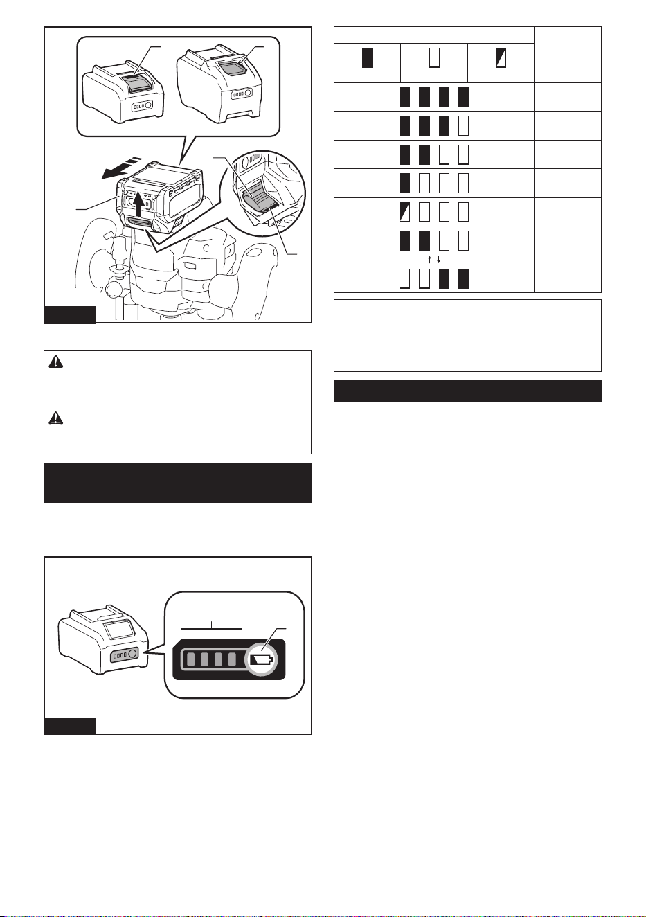
To install the battery cartridge, align the tongue on the
battery cartridge with the groove in the housing and slip
it into place. Insert it all the way until it locks in place
with a little click. If you can see the red indicator as
shown in the gure, it is not locked completely.
To remove the battery cartridge, slide it from the tool
while sliding the button on the front of the cartridge.
7 ENGLISH
1
2
3
1
1
Fig.1
► 1. Red indicator 2. Button 3. Battery cartridge
CAUTION: Always install the battery cartridge
fully until the red indicator cannot be seen. If not,
it may accidentally fall out of the tool, causing injury to
you or someone around you.
CAUTION: Do not install the battery cartridge
forcibly. If the cartridge does not slide in easily, it is
not being inserted correctly.
Indicating the remaining battery
capacity
Press the check button on the battery cartridge to indi-
cate the remaining battery capacity. The indicator lamps
light up for a few seconds.
1
2
Fig.2
► 1. Indicator lamps 2. Check button
Indicator lamps Remaining
capacity
Lighted O Blinking
75% to 100%
50% to 75%
25% to 50%
0% to 25%
Charge the
battery.
The battery
may have
malfunctioned.
NOTE: Depending on the conditions of use and the
ambient temperature, the indication may dier slightly
from the actual capacity.
NOTE: The rst (far left) indicator lamp will blink when
the battery protection system works.
Tool / battery protection system
The tool is equipped with a tool/battery protection sys-
tem. This system automatically cuts o power to the
motor to extend tool and battery life. The tool will auto-
matically stop during operation if the tool or battery is
placed under one of the following conditions:
Overload protection
When the tool/battery is operated in a manner that
causes it to draw an abnormally high current, the tool
automatically stops. In this situation, turn the tool o
and stop the application that caused the tool to become
overloaded. Then turn the tool on to restart.
Overheat protection
When the tool or battery is overheated, the tool stops
automatically and lamps blink. In this case, turn o the
tool by pressing the lock/unlock button, removing the
battery, or leaving the tool for 60 seconds without any
operation. Let the tool and battery cool before turning
the tool on again.
Overdischarge protection
When the battery capacity is not enough, the tool stops
automatically. In this case, remove the battery from the
tool and charge the battery.
8 ENGLISH
Protections against other causes
Protection system is also designed for other causes
that could damage the tool and allows the tool to stop
automatically. Take all the following steps to clear the
causes, when the tool has been brought to a temporary
halt or stop in operation.
1. Turn the tool o, and then turn it on again to
restart.
2. Charge the battery(ies) or replace it/them with
recharged battery(ies).
3. Let the tool and battery(ies) cool down.
If no improvement can be found by restoring protection
system, then contact your local Makita Service Center.
Switch action
To turn on the tool, press the lock/unlock button. The
tool turns into the standby mode. To start the tool, pull
the switch trigger in the standby mode. To stop the tool,
release the switch trigger and the tool turns into the
standby mode. To turn o the tool, press the lock/unlock
button in the standby mode.
For continuous operation, pull the switch trigger and
press the lock button. Pull the switch trigger again to
cancel the continuous operation and release the switch
trigger to stop the tool.
1
3
2
Fig.3
► 1. Lock/unlock button 2. Lock button 3. Switch
trigger
NOTE: If the tool is left for 5 seconds without any
operation in the standby mode or 5 seconds after
releasing the switch trigger, the tool automatically
turns o.
Lighting up the lamps
CAUTION: Do not look in the light or see the
source of light directly.
NOTICE: When the tool is overheated, the lamp
blinks. Cool down the tool fully before operating
the tool again.
To turn on the lamps, press the lock/unlock button. The
lamps keep on lighting during operation. The lamps go
o when the tool is left for 5 seconds without any oper-
ation in the standby mode or 5 seconds after releasing
the switch trigger.
1
Fig.4
► 1. Lamp
NOTE: Use a dry cloth to wipe the dirt o the lens
of the lamp. Be careful not to scratch the lens of the
lamp, or it may lower the illumination.
Speed adjusting dial
The rotation speed of the tool can be changed by turn-
ing the speed adjusting dial. The table below shows
the number on the dial and the corresponding rotation
speed.
1
Fig.5
► 1. Speed adjusting dial
Number Speed
1 8,000/min
2 12,500/min
3 17,000/min
4 21,000/min
5 25,000/min
CAUTION: Do not change the rotation speed
during operation. Otherwise unexpected reaction of
the tool may cause an injury.
9 ENGLISH
NOTICE: If the tool is operated continuously at
low speed for a long time, the motor will get over-
loaded, resulting in tool malfunction.
NOTICE: The speed adjusting dial can be turned
only as far as 5 and back to 1. Do not force it past
5 or 1, or the speed adjusting function may no
longer work.
Electronic function
The tool is equipped with the electronic functions for
easy operation.
• Constant speed control
The speed control function provides the constant
rotation speed regardless of load conditions.
• Soft start
The soft-start function minimizes start-up shock,
and makes the tool start smoothly.
• Soft brake
The tool stops gently with the soft brake. The soft
brake prevents damage to the workpiece due
to recoil and allows you to start next operation
earlier.
If the tool consistently fails to stop the router bit
after the switch is turned o, have the tool ser-
viced at a Makita service center.
ASSEMBLY
CAUTION: Always be sure that the tool is
switched o and the battery cartridge is removed
before carrying out any work on the tool.
Installing or removing router bit
CAUTION: Install the router bit securely.
Always use only the wrench provided with the
tool. A loose or overtightened router bit can be
dangerous.
CAUTION: Always use a collet cone which is
suitable for the shank diameter of the router bit.
CAUTION: Do not tighten the collet nut with-
out inserting a router bit or install a small shank
router bit without using a collet sleeve. Either can
lead to breakage of the collet cone.
CAUTION: Use only router bits of which the
maximum speed, as indicated on the router bit,
does exceed the maximum speed of the router.
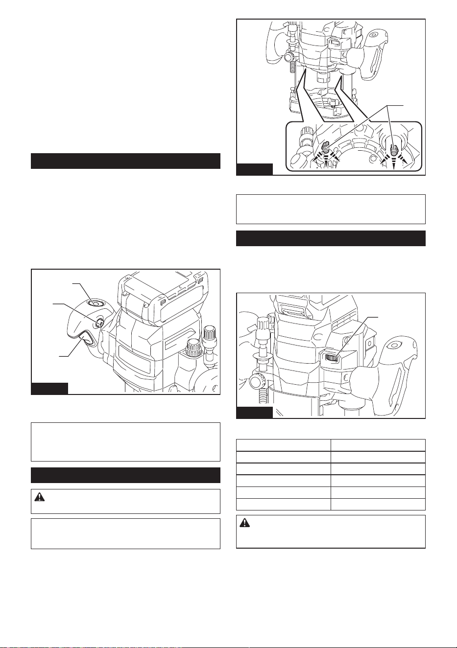
Insert the router bit all the way into the collet cone.
Press the shaft lock and tighten the collet nut with the
wrench.
1
2
3
4
5
Fig.6
► 1. Shaft lock 2. Loosen 3. Tighten 4. Wrench
5. Collet nut
When using the router bit with smaller shank diameter,
rst insert the appropriate collet sleeve into the collet
cone, then install the router bit.
1
2
4
3
Fig.7
► 1. Collet cone 2. Collet nut 3. Collet sleeve
4. Router bit
To remove the router bit, follow the installation proce-
dure in reverse.
Installing or removing the chip
deector
Optional accessory
To install the chip deector, insert the chip deector into
a groove, aligning the hole of the chip deector with the
protrusion.
1
3
2
Fig.8
► 1. Chip deector 2. Hole 3. Protrusion
10 ENGLISH
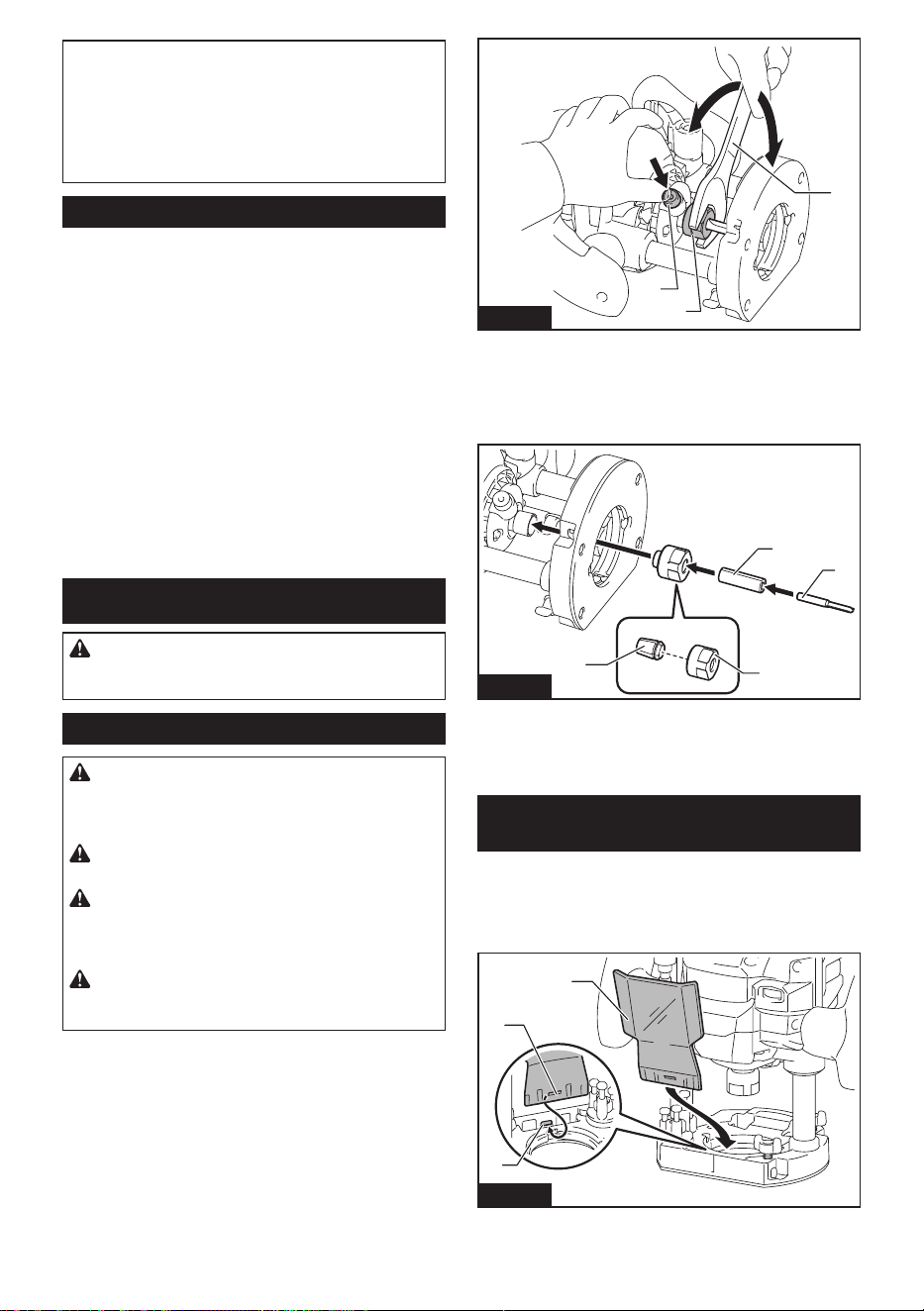
To remove the chip deector, tilt the upper part of the
chip deector forwards and pull it out.
Fig.9
OPERATION
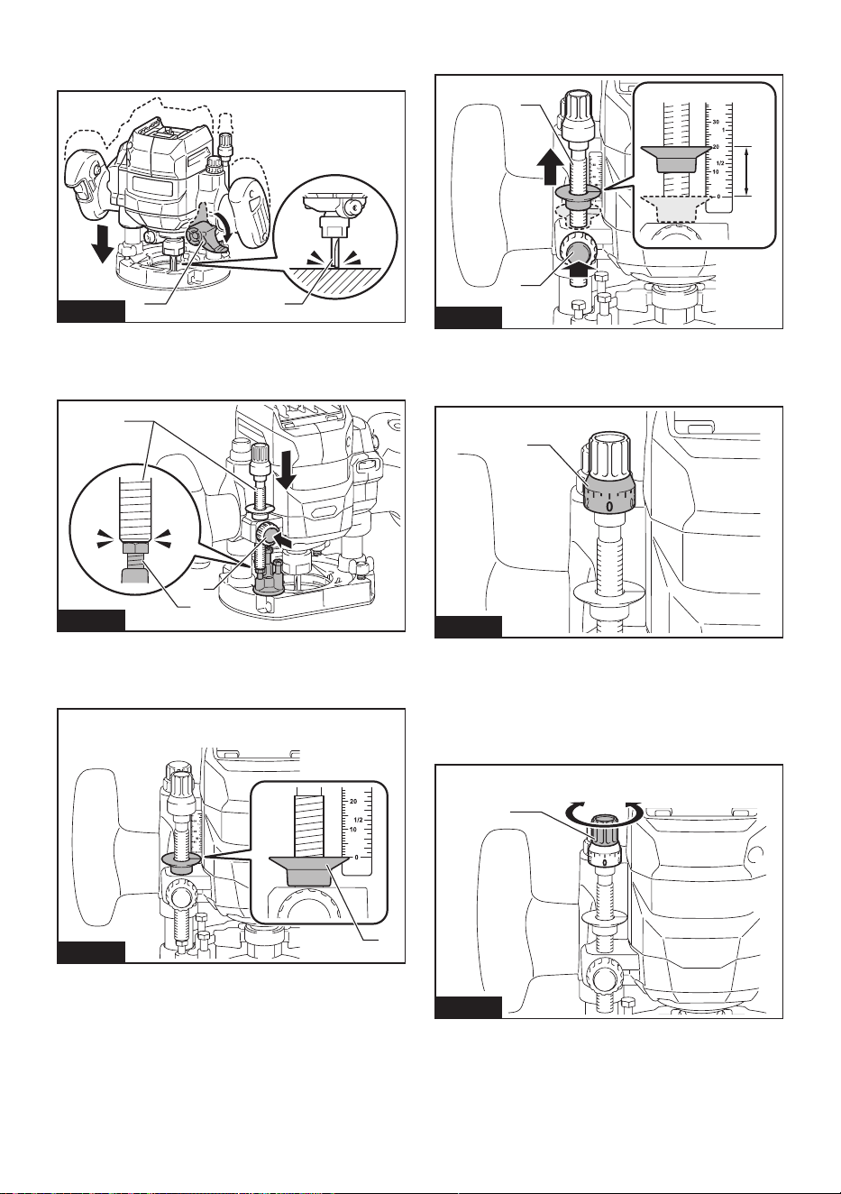
Adjusting the cutting depth
To adjust the cutting depth, release the lock lever, then
lower the body. After the adjustment, turn the lock lever
rmly to secure the body.
1
Fig.10
► 1. Lock lever
Adjusting cutting depth with the
stopper screw
1. Place the tool on the at surface.
2. Select the stopper screw by rotating the stopper
base.
1
2
Fig.11
► 1. Stopper screw 2. Stopper base
To adjust the height of the stopper screws, use the
wrench or driver.
Fig.12
3. Loosen the xing nut, then pull up the stopper pole
while pressing the feed button.
1
2
3
Fig.13
► 1. Stopper pole 2. Fixing nut 3. Feed button
11 ENGLISH
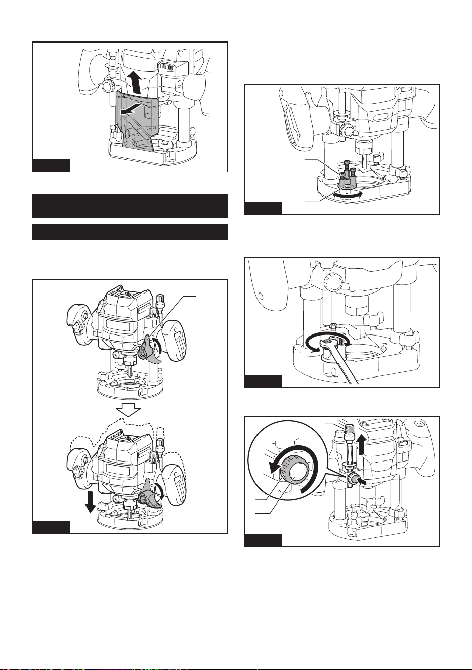
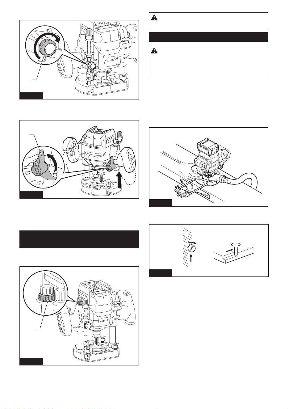
4. Release the lock lever, push down the tool until
the tip of the router bit touches the at surface, and then
turn the lock lever to secure the tool.
21
Fig.14
► 1. Lock lever 2. Router bit
5. Press down the stopper pole while pressing the
feed button until it contacts the stopper screw.
1
3
2
Fig.15
► 1. Stopper pole 2. Stopper screw 3. Feed button
6. Slide the depth pointer so that the pointer indi-
cates "0" on the scale.
1
Fig.16
► 1. Depth pointer
7. Adjust the cutting depth by pulling up the stopper
pole while pressing the feed button.
1
2
3
Fig.17
► 1. Stopper pole 2. Feed button 3. Cutting depth
8. To perform ne adjustment of the cutting depth,
turn the dial on the stopper pole so that it indicates "0".
1
Fig.18
► 1. Dial
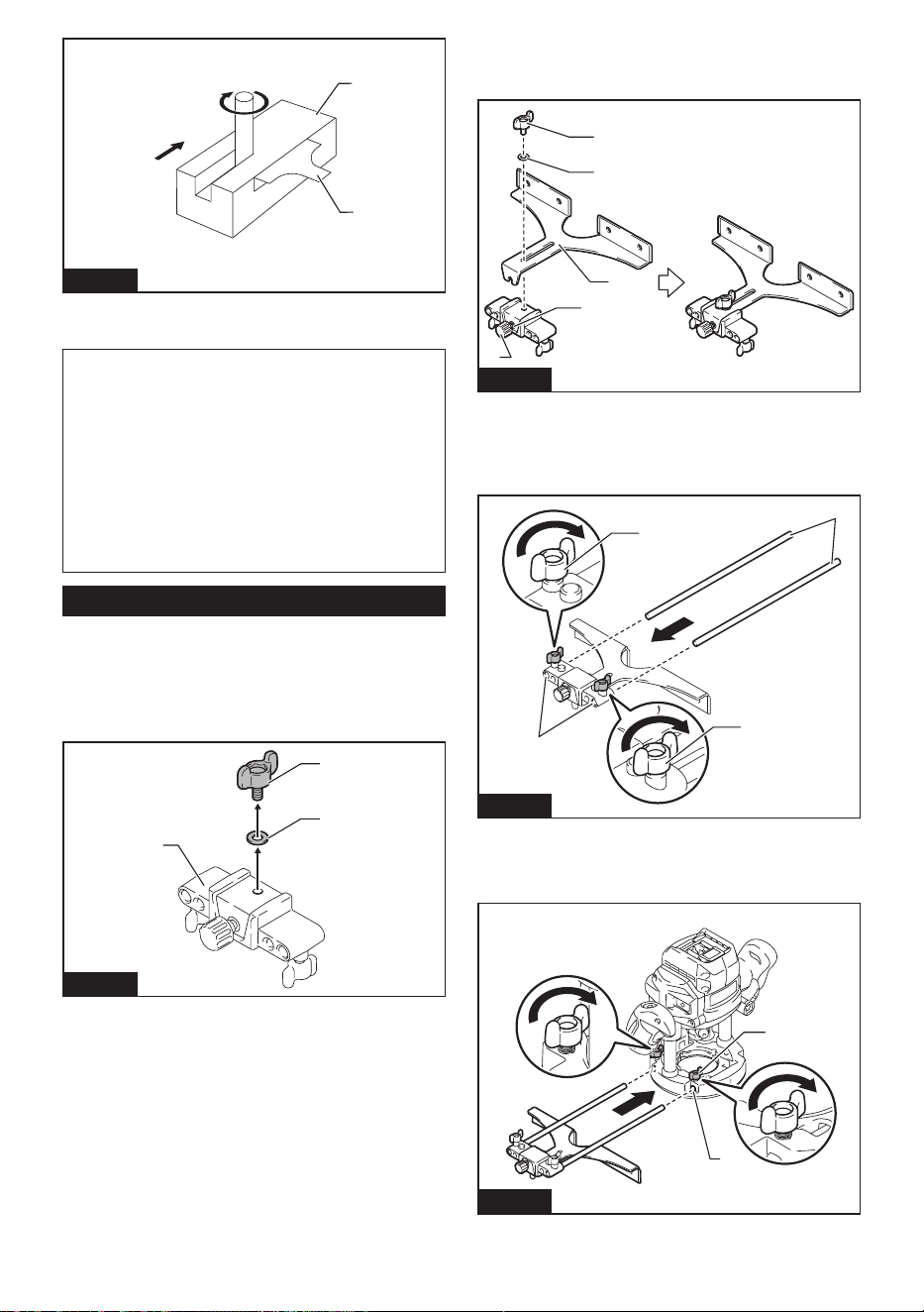
9. Turn the head of the stopper pole to obtain the
desired depth. To increase the depth, turn the head
counterclockwise. To decrease the depth, turn the head
clockwise. (The depth changes by 1 mm (3/64″) per one
revolution.)
1
Fig.19
► 1. Head of the stopper pole
12 ENGLISH
10. Tighten the xing nut to secure the stopper pole.
1
Fig.20
► 1. Fixing nut
11. Release the lock lever.
1
Fig.21
► 1. Lock lever
By pushing down the tool until the stopper pole meets
the stopper screw, you can obtain the depth of cut which
you adjusted by above procedure.
Adjusting the upper limit of the tool
body
The upper limit of the tool body can be adjusted by
turning the nylon nut.
1
Fig.22
► 1. Nylon nut
CAUTION: Do not lower the nylon nut too low.
The router bit will protrude dangerously.
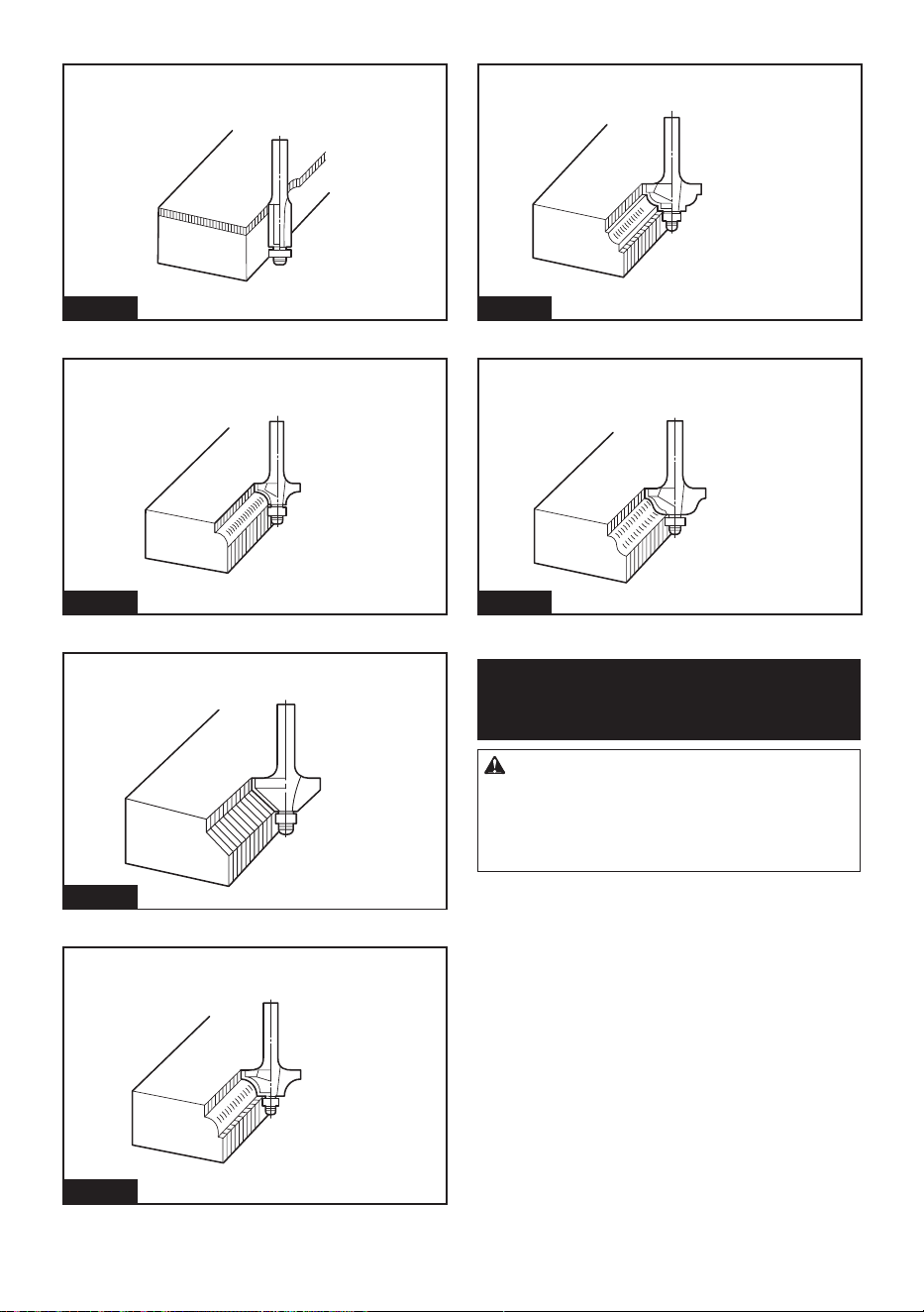
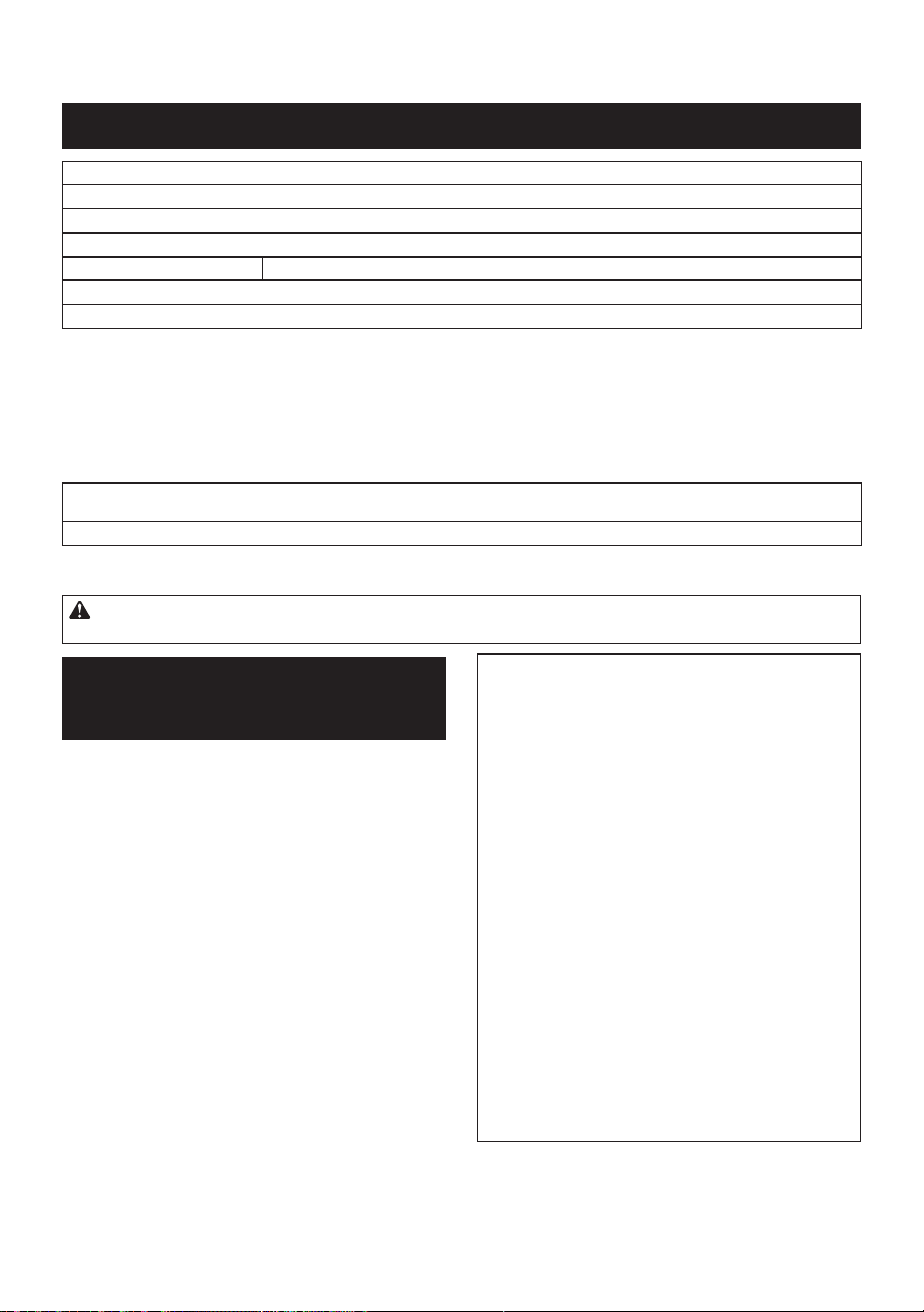
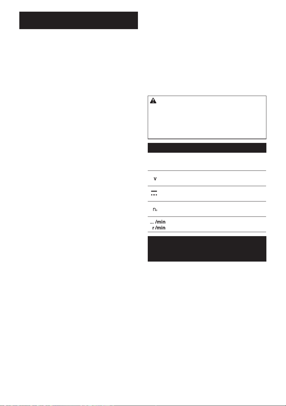
General operation
CAUTION: Before operation, always make
sure that the tool body automatically rises to
the upper limit and the router bit does not pro-
trude from the tool base when the lock lever is
loosened.
1. Set the base on the workpiece to be cut without
the router bit making any contact.
2. Turn the tool on and wait until the router bit attains
full speed.
3. Lower the tool body and move the tool forward
over the workpiece surface, keeping the base ush and
advancing smoothly until the cutting is complete.
Fig.23
When doing edge cutting, the workpiece surface should
be on the left side of the router bit in the feed direction.
4
4
3
1
2
2
Fig.24
► 1. Workpiece 2. Bit revolving direction 3. View from
the top of the tool 4. Feed direction
When using the straight guide or the trimmer guide,
be sure to keep it on the right side in the feed direc-
tion. This will help to keep it ush with the side of the
workpiece.
13 ENGLISH
1
2
4
3
Fig.25
► 1. Feed direction 2. Bit revolving direction
3. Workpiece 4. Straight guide
NOTE: Moving the tool forward too fast may cause
a poor quality of cut, or damage to the router bit or
motor. Moving the tool forward too slowly may burn
and mar the cut.
The proper feed rate will depend on the router bit
size, the kind of workpiece and depth of cut.
Before beginning the cut on the actual workpiece,
make a sample cut on a piece of scrap lumber to
consider the appropriate feed speed.
You can also conrm the router bit setting by measur-
ing the sample cut.
Using the straight guide
Optional accessory
The straight guide is eectively used for straight cut
when chamfering or grooving.
1. Remove the clamping screw and the washer from
the guide holder.
1
2
3
Fig.26
► 1. Guide holder 2. Clamping screw 3. Washer
2. Loosen the adjusting screw to make a groove.
Fit the straight guide into the groove, then mount the
washer and tighten the clamping screw.
1
5
4
3
2
Fig.27
► 1. Adjusting screw 2. Groove 3. Straight guide
4. Washer 5. Clamping screw
3. Mount rod 8 to the slots in the guide holder and
tighten the clamping screws.
1
3
2
3
Fig.28
► 1. Rod 8 2. Slot 3. Clamping screw
4. Install the straight guide to the slots in the tool
base, and then tighten the clamping screws.
1
2
Fig.29
► 1. Slot 2. Clamping screw
14 ENGLISH
5. Loosen the clamping screw and adjust the dis-
tance between the router bit and the straight guide by
turning the adjusting screw (1.5 mm (1/16″) per turn).
At the desired distance, tighten the clamping screw to
secure the straight guide.
2
1
3
Fig.30
► 1. Clamping screw 2. Adjusting screw 3. Straight
guide
6. Move the tool with the straight guide ush with the
side of the workpiece.
Fig.31
Wider straight guide of desired dimensions may be
made by using the convenient holes in the guide to bolt
on extra pieces of wood.
1
2
Fig.32
► 1. Wood 2. Straight guide
If the distance (A) between the side of the workpiece
and the cutting position is too wide for the straight
guide, or if the side of the workpiece is not straight, the
straight guide cannot be used.
In this case, rmly clamp a straight board to the work-
piece and use it as a guide against the base. Feed the
tool in the direction of the arrow.
A
Fig.33
Using the ne adjusting straight guide
Optional accessory
The ne adjusting straight guide can adjust the distance
more accurately than the straight guide.
1
Fig.34
► 1. Fine adjusting straight guide
1. Mount rod 8 to the slots in the guide holder and
tighten the thumb screw (M5 x 14 mm).
2. Install the ne adjusting straight guide to the tool
base. Tighten the clamping screws on the tool base.
3. Loosen the thumb screw (M6 x 50 mm) and adjust
the distance between the router bit and the straight
guide by turning the adjusting screw (1 mm (3/64″) per
turn). At the desired distance, tighten the thumb screw
(M6 x 50 mm) to secure the straight guide.
The scale ring can be rotated separately from the
adjusting screw, so scale unit can be aligned to zero (0).
2
1
3
4
5
Fig.35
► 1. Adjusting screw 2. Thumb screw (M6 x 50 mm)
3. Thumb screw (M5 x 14 mm) 4. Guide holder
5. Scale ring
15 ENGLISH
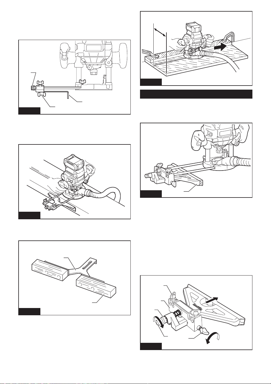
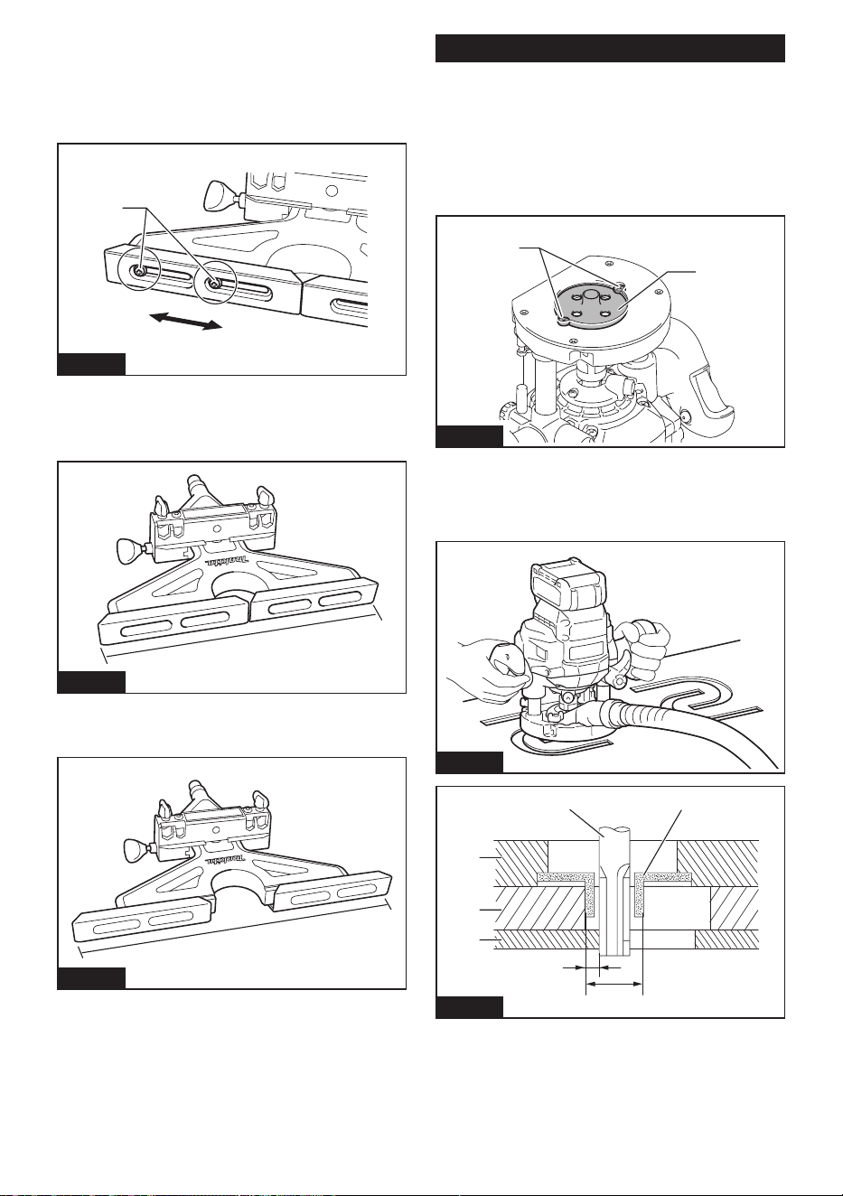
Adjusting guide shoe width
Guide shoe is adjustable in the range from 280 mm to
350 mm (11″ to 13-3/4″).
1. Loosen the screws and move the guide shoe width
to adjust.
1
Fig.36
► 1. Screw
2. After adjusting the width, tighten the screws.
Minimum opening width
1
Fig.37
► 1. 280 mm (11″)
Maximum opening width
1
Fig.38
► 1. 350 mm (13-3/4″)
Using the templet guide
Optional accessory
The templet guide allows for repetitive cut with templet
patterns by using a templet.
1. Loosen the screws on the tool base and remove
them.
2. Place the templet guide on the base, and then
tighten the screws.
1
2
Fig.39
► 1. Templet guide 2. Screw
3. Place the tool on the templet and move the tool
so that the templet guide slides along the side of the
templet.
Fig.40
17
6
5
2
3
4
Fig.41
► 1. Router bit 2. Base 3. Templet 4. Workpiece
5. Distance (X) 6. Outside diameter of the templet
guide 7. Templet guide
16 ENGLISH
NOTE: The workpiece will be cut a slightly dierent
size from the templet. Allow for the distance (X)
between the router bit and the outside of the templet
guide. The distance (X) can be calculated by using
the following equation:
Distance (X) = (outside diameter of the templet guide
- router bit diameter) / 2
Using the trimmer guide
Optional accessory
NOTE: When using the trimmer guide, rod 8 and the
guide holder are also required.
The trimmer guide allows for trimming the curved side
like veneers for furniture by moving the guide roller
along the side of the workpiece.
1
2
3
Fig.42
► 1. Trimmer guide 2. Rod 8 3. Guide holder
1. Install the trimmer guide and rods to the guide
holder.
2. Insert rods to the slots in the guide holder and
tighten the clamping screw.
3. Loosen the clamping screw and adjust the dis-
tance between the router bit and the trimmer guide by
turning the adjusting screw (1.5 mm (1/16″) per turn).
At the desired distance, tighten the clamping screw to
secure the trimmer guide.
4. Move the tool with the guide roller riding the side
of the workpiece.
3
2
1
Fig.43
► 1. Router bit 2. Guide roller 3. Workpiece
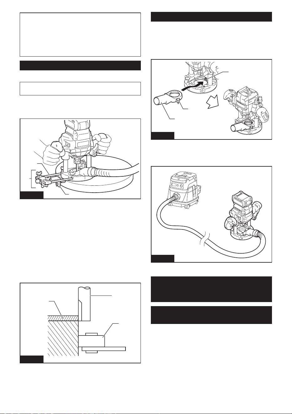
Dust nozzle
Installing the dust nozzle enables to connect a Makita
vacuum cleaner to the tool.
1. Install the dust nozzle on the tool base using the
thumb screw so that protrusion on the dust nozzle t to
the notch in the tool base.
1
3
2
Fig.44
► 1. Dust nozzle 2. Thumb screw 3. Notch
2. Connect a Makita vacuum cleaner to the dust
nozzle.
Fig.45
WIRELESS ACTIVATION
FUNCTION
What you can do with the wireless
activation function
The wireless activation function enables clean and com-
fortable operation. By connecting a supported vacuum
cleaner to the tool, you can run the vacuum cleaner
automatically along with the switch operation of the tool.
17 ENGLISH
Fig.46
To use the wireless activation function, prepare follow-
ing items:
• A wireless unit (optional accessory)
• A vacuum cleaner which supports the wireless
activation function
The overview of the wireless activation function
setting is as follows. Refer to each section for detail
procedures.
1. Installing the wireless unit
2. Tool registration for the vacuum cleaner
3. Starting the wireless activation function
Installing the wireless unit
Optional accessory
CAUTION: Place the tool on a at and stable
surface when installing the wireless unit.
NOTICE: Clean the dust and dirt on the tool
before installing the wireless unit. Dust or dirt
may cause malfunction if it comes into the slot of the
wireless unit.
NOTICE: To prevent the malfunction caused by
static, touch a static discharging material, such
as a metal part of the tool, before picking up the
wireless unit.
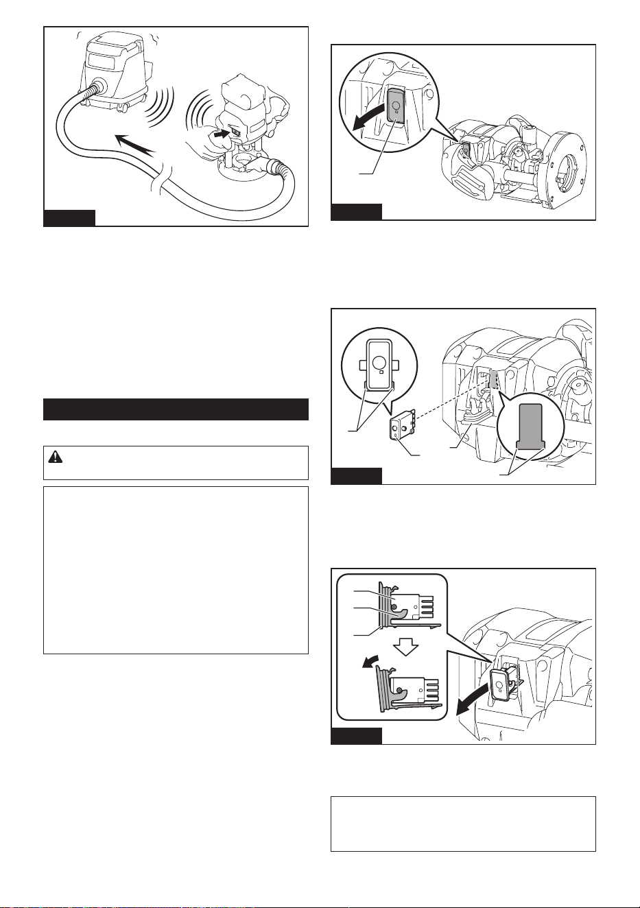
NOTICE: When installing the wireless unit,
always be sure that the wireless unit is inserted
in the correct direction and the lid is completely
closed.
1. Open the lid on the tool as shown in the gure.
1
Fig.47
► 1. Lid
2. Insert the wireless unit to the slot and then close
the lid.
When inserting the wireless unit, align the projections
with the recessed portions on the slot.
1
2
3
4
Fig.48
► 1. Wireless unit 2. Projection 3. Lid 4. Recessed
portion
When removing the wireless unit, open the lid slowly.
The hooks on the back of the lid will lift the wireless unit
as you pull up the lid.
1
2
3
Fig.49
► 1. Wireless unit 2. Hook 3. Lid
After removing the wireless unit, keep it in the supplied
case or a static-free container.
NOTICE: Always use the hooks on the back of
the lid when removing the wireless unit. If the
hooks do not catch the wireless unit, close the lid
completely and open it slowly again.
18 ENGLISH
Tool registration for the vacuum
cleaner
NOTE: A Makita vacuum cleaner supporting the
wireless activation function is required for the tool
registration.
NOTE: Finish installing the wireless unit to the tool
before starting the tool registration.
NOTE: During the tool registration, do not pull the
switch trigger or turn on the power switch on the
vacuum cleaner.
NOTE: Refer to the instruction manual of the vacuum
cleaner, too.
If you wish to activate the vacuum cleaner along with
the switch operation of the tool, nish the tool registra-
tion beforehand.
1. Install the batteries to the vacuum cleaner and the
tool.
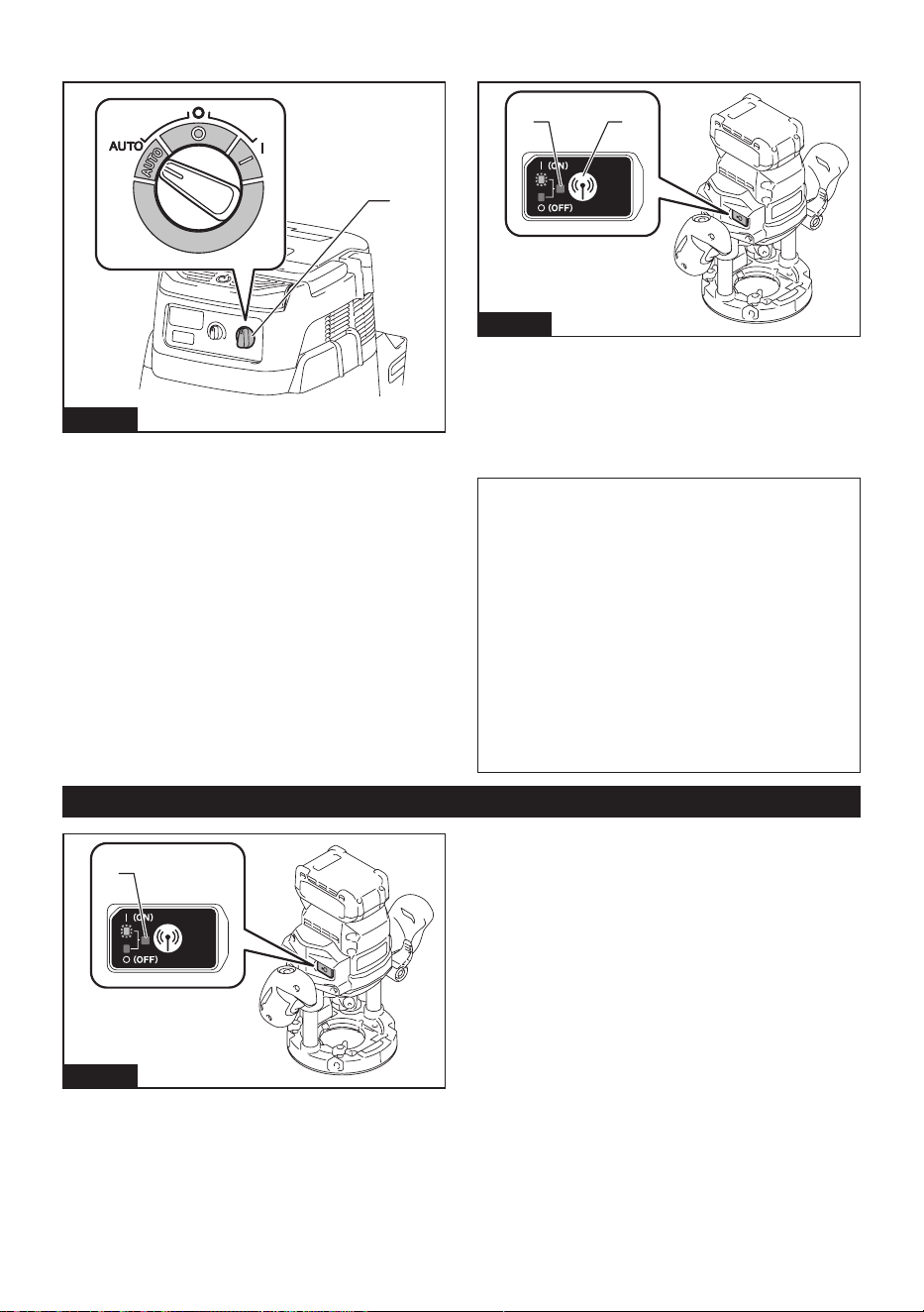
2. Set the stand-by switch on the vacuum cleaner to
"AUTO".
1
Fig.50
► 1. Stand-by switch
3. Press the wireless activation button on the vac-
uum cleaner for 3 seconds until the wireless activation
lamp blinks in green. And then press the wireless acti-
vation button on the tool in the same way.
21
12
Fig.51
► 1. Wireless activation button 2. Wireless activation
lamp
If the vacuum cleaner and the tool are linked success-
fully, the wireless activation lamps will light up in green
for 2 seconds and start blinking in blue.
NOTE: The wireless activation lamps nish blinking
in green after 20 seconds elapsed. Press the wireless
activation button on the tool while the wireless acti-
vation lamp on the cleaner is blinking. If the wireless
activation lamp does not blink in green, push the wire-
less activation button briey and hold it down again.
NOTE: When performing two or more tool registra-
tions for one vacuum cleaner, nish the tool registra-
tion one by one.
Starting the wireless activation
function
NOTE: Finish the tool registration for the vacuum
cleaner prior to the wireless activation.
NOTE: Refer to the instruction manual of the vacuum
cleaner, too.
After registering a tool to the vacuum cleaner, the vac-
uum cleaner will automatically run along with the switch
operation of the tool.
1. Install the wireless unit to the tool.
2. Connect the hose of the vacuum cleaner with the
tool.
Fig.52
19 ENGLISH
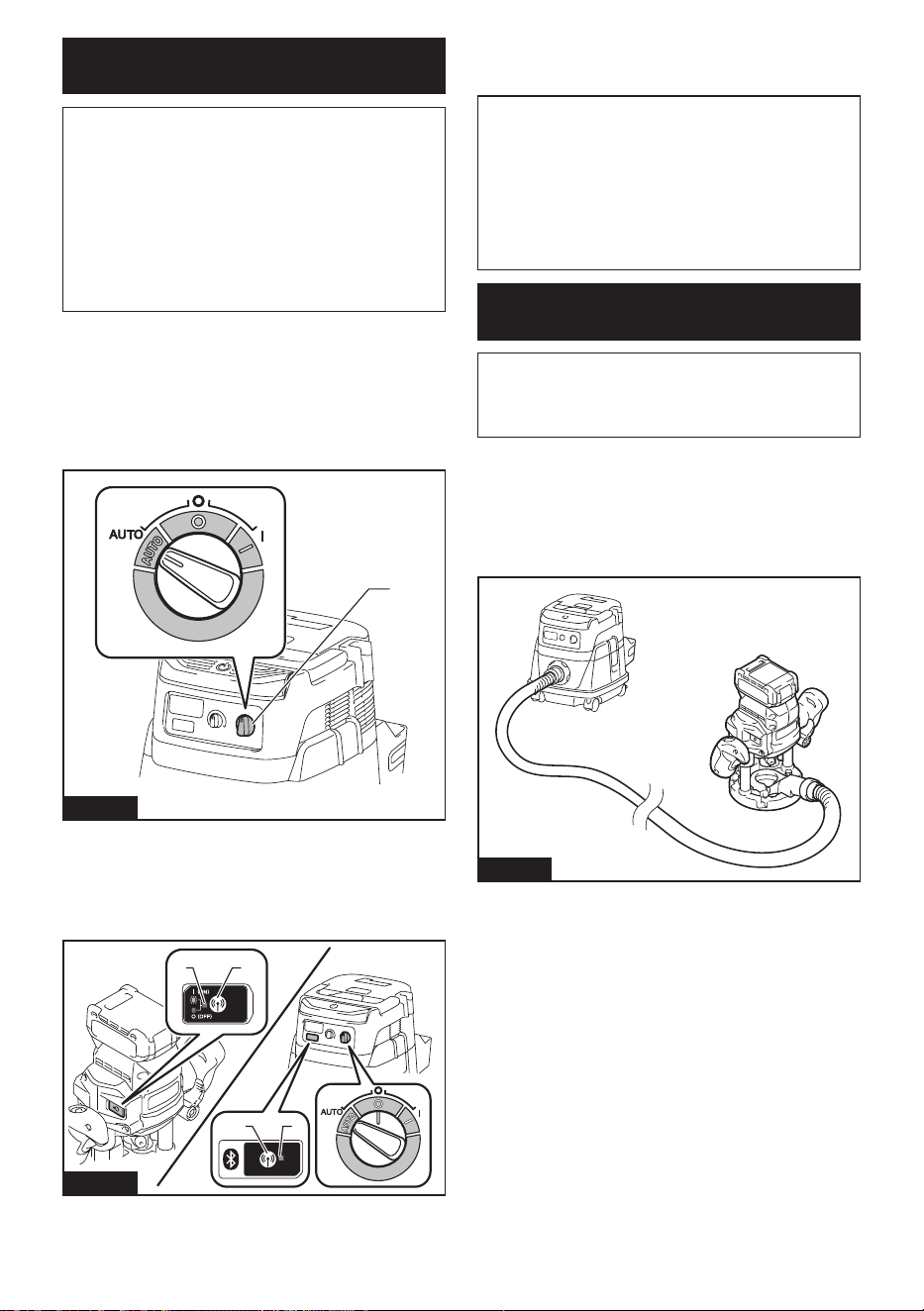
3. Set the stand-by switch on the vacuum cleaner to
"AUTO".
1
Fig.53
► 1. Stand-by switch
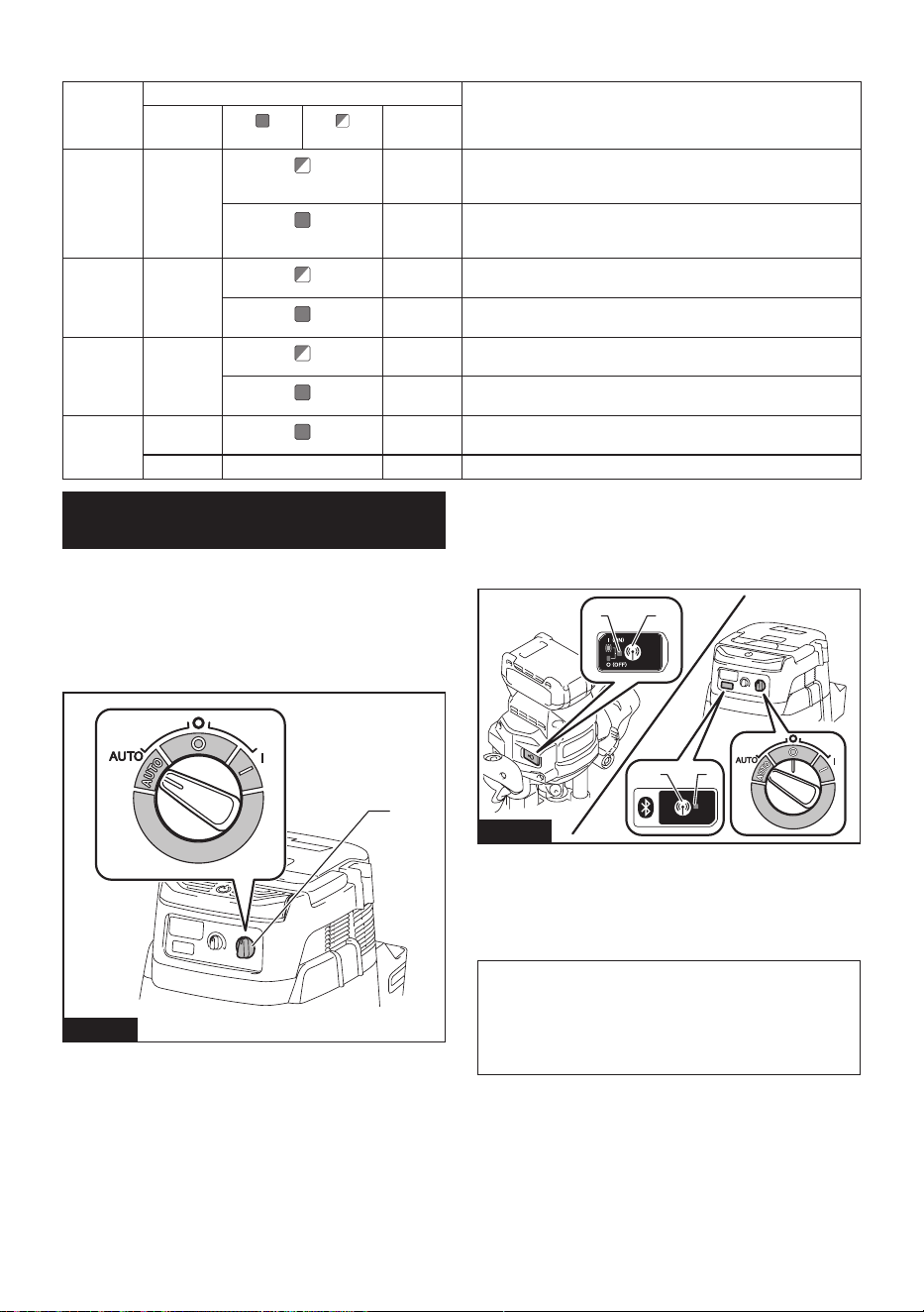
4. Push the wireless activation button on the tool
briey. The wireless activation lamp will blink in blue.
2 1
Fig.54
► 1. Wireless activation button 2. Wireless activation
lamp
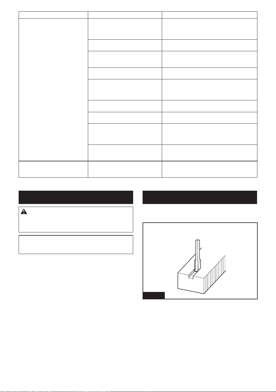
5. Turn on the tool. Check if the vacuum cleaner runs
while the tool is operating.
To stop the wireless activation of the vacuum cleaner,
push the wireless activation button on the tool.
NOTE: The wireless activation lamp on the tool will
stop blinking in blue when there is no operation for
2 hours. In this case, set the stand-by switch on the
vacuum cleaner to "AUTO" and push the wireless
activation button on the tool again.
NOTE: The vacuum cleaner starts/stops with a delay.
There is a time lag when the vacuum cleaner detects
a switch operation of the tool.
NOTE: The transmission distance of the wireless unit
may vary depending on the location and surrounding
circumstances.
NOTE: When two or more tools are registered to
one vacuum cleaner, the vacuum cleaner may start
running even if you do not turn on your tool because
another user is using the wireless activation function.
Description of the wireless activation lamp status
1
Fig.55
► 1. Wireless activation lamp
20 ENGLISH
The wireless activation lamp shows the status of the wireless activation function. Refer to the table below for the
meaning of the lamp status.
Status Wireless activation lamp Description
Color
On
Blinking
Duration
Standby Blue
2 hours The wireless activation of the vacuum cleaner is available. The
lamp will automatically turn o when no operation is performed
for 2 hours.
When
the tool is
running.
The wireless activation of the vacuum cleaner is available and the
tool is running.
Tool
registration
Green
20 seconds Ready for the tool registration. Waiting for the registration by the
vacuum cleaner.
2 seconds The tool registration has been nished. The wireless activation
lamp will start blinking in blue.
Cancelling
tool
registration
Red
20 seconds Ready for the cancellation of the tool registration. Waiting for the
cancellation by the vacuum cleaner.
2 seconds The cancellation of the tool registration has been nished. The
wireless activation lamp will start blinking in blue.
Others Red
3 seconds The power is supplied to the wireless unit and the wireless activa-
tion function is starting up.
O - - The wireless activation of the vacuum cleaner is stopped.
Cancelling tool registration for the
vacuum cleaner
Perform the following procedure when cancelling the
tool registration for the vacuum cleaner.
1. Install the batteries to the vacuum cleaner and the
tool.
2. Set the stand-by switch on the vacuum cleaner to
"AUTO".
1
Fig.56
► 1. Stand-by switch
3. Press the wireless activation button on the vac-
uum cleaner for 6 seconds. The wireless activation
lamp blinks in green and then become red. After that,
press the wireless activation button on the tool in the
same way.
21
12
Fig.57
► 1. Wireless activation button 2. Wireless activation
lamp
If the cancellation is performed successfully, the wire-
less activation lamps will light up in red for 2 seconds
and start blinking in blue.
NOTE: The wireless activation lamps nish blinking in
red after 20 seconds elapsed. Press the wireless acti-
vation button on the tool while the wireless activation
lamp on the cleaner is blinking. If the wireless acti-
vation lamp does not blink in red, push the wireless
activation button briey and hold it down again.

21 ENGLISH
Troubleshooting for wireless activation function
Before asking for repairs, conduct your own inspection rst. If you nd a problem that is not explained in the manual,
do not attempt to dismantle the tool. Instead, ask Makita Authorized Service Centers, always using Makita replace-
ment parts for repairs.
State of abnormality Probable cause (malfunction) Remedy
The wireless activation lamp does
not light/blink.
The wireless unit is not installed into
the tool.
The wireless unit is improperly installed
into the tool.
Install the wireless unit correctly.
The terminal of the wireless unit and/or
the slot is dirty.
Gently wipe o dust and dirt on the terminal of the
wireless unit and clean the slot.
The wireless activation button on the
tool has not been pushed.
Push the wireless activation button on the tool
briey.
The stand-by switch on the vacuum
cleaner is not set to "AUTO".
Set the stand-by switch on the vacuum cleaner to
"AUTO".
No power supply Supply the power to the tool and the vacuum
cleaner.
Cannot nish tool registration / can-
celling tool registration successfully.
The wireless unit is not installed into
the tool.
The wireless unit is improperly installed
into the tool.
Install the wireless unit correctly.
The terminal of the wireless unit and/or
the slot is dirty.
Gently wipe o dust and dirt on the terminal of the
wireless unit and clean the slot.
The stand-by switch on the vacuum
cleaner is not set to "AUTO".
Set the stand-by switch on the vacuum cleaner to
"AUTO".
No power supply Supply the power to the tool and the vacuum
cleaner.
Incorrect operation Push the wireless activation button briey and
perform the tool registration/cancellation procedures
again.
The tool and vacuum cleaner are away
from each other (out of the transmission
range).
Get the tool and vacuum cleaner closer to each
other. The maximum transmission distance is
approximately 10 m however it may vary according
to the circumstances.
Before nishing the tool registration/
cancellation;
- the switch of the tool is turned on or;
- the power button on the vacuum
cleaner is turned on.
Push the wireless activation button briey and
perform the tool registration/cancellation procedures
again.
The tool registration procedures for
the tool or vacuum cleaner have not
nished.
Perform the tool registration procedures for both the
tool and the vacuum cleaner at the same timing.
Radio disturbance by other appliances
which generate high-intensity radio
waves.
Keep the tool and vacuum cleaner away from the
appliances such as Wi-Fi devices and microwave
ovens.
22 ENGLISH
State of abnormality Probable cause (malfunction) Remedy
The vacuum cleaner does not run
along with the switch operation of
the tool.
The wireless unit is not installed into
the tool.
The wireless unit is improperly installed
into the tool.
Install the wireless unit correctly.
The terminal of the wireless unit and/or
the slot is dirty.
Gently wipe o dust and dirt on the terminal of the
wireless unit and clean the slot.
The wireless activation button on the
tool has not been pushed.
Push the wireless activation button briey and make
sure that the wireless activation lamp is blinking
in blue.
The stand-by switch on the vacuum
cleaner is not set to "AUTO".
Set the stand-by switch on the vacuum cleaner to
"AUTO".
More than 10 tools are registered to the
vacuum cleaner.
Perform the tool registration again.
If more than 10 tools are registered to the vacuum
cleaner, the tool registered earliest will be cancelled
automatically.
The vacuum cleaner erased all tool
registrations.
Perform the tool registration again.
No power supply Supply the power to the tool and the vacuum
cleaner.
The tool and vacuum cleaner are away
from each other (out of the transmission
range).
Get the tool and vacuum cleaner closer each other.
The maximum transmission distance is approxi-
mately 10 m however it may vary according to the
circumstances.
Radio disturbance by other appliances
which generate high-intensity radio
waves.
Keep the tool and vacuum cleaner away from the
appliances such as Wi-Fi devices and microwave
ovens.
The vacuum cleaner runs while the
tool is not operating.
Other users are using the wireless
activation of the vacuum cleaner with
their tools.
Turn o the wireless activation button of the other
tools or cancel the tool registration of the other
tools.
MAINTENANCE
CAUTION: Always be sure that the tool is
switched o and the battery cartridge is removed
before attempting to perform inspection or
maintenance.
NOTICE: Never use gasoline, benzine, thinner,
alcohol or the like. Discoloration, deformation or
cracks may result.
To maintain product SAFETY and RELIABILITY,
repairs, any other maintenance or adjustment should
be performed by Makita Authorized or Factory Service
Centers, always using Makita replacement parts.
ROUTER BITS
Optional accessory
Straight bit
Fig.58
23 ENGLISH
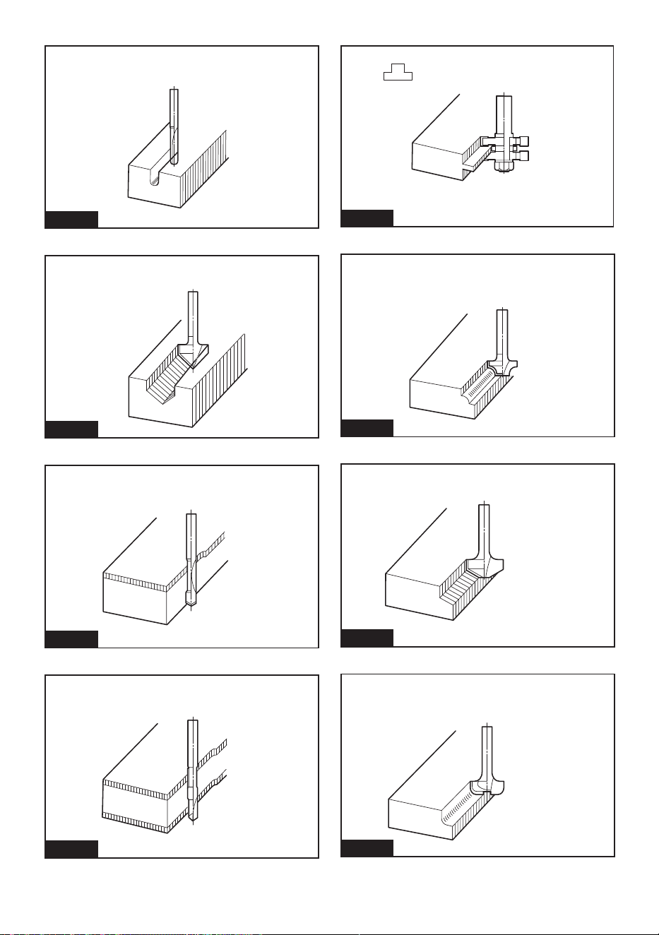
“U”Grooving bit
Fig.59
“V”Grooving bit
Fig.60
Drill point ush trimming bit
Fig.61
Drill point double ush trimming bit
Fig.62
Board-jointing bit
Fig.63
Corner rounding bit
Fig.64
Chamfering bit
Fig.65
Cove beading bit
Fig.66
24 ENGLISH
Ball bearing ush trimming bit
Fig.67
Ball bearing corner rounding bit
Fig.68
Ball bearing chamfering bit
Fig.69
Ball bearing beading bit
Fig.70
Ball bearing cove beading bit
Fig.71
Ball bearing roman ogee bit
Fig.72
OPTIONAL
ACCESSORIES
CAUTION: These accessories or attachments
are recommended for use with your Makita tool
specied in this manual. The use of any other
accessories or attachments might present a risk of
injury to persons. Only use accessory or attachment
for its stated purpose.
If you need any assistance for more details regard-
ing these accessories, ask your local Makita Service
Center.
• Straight and groove forming bits
• Edge forming bits
• Laminate trimming bits
• Straight guide assembly
• Fine adjusting straight guide assembly
• Trimmer guide assembly
• Guide holder
• Templet guide
• Templet guide adapter
• Collet nut
• Collet cone
• Collet sleeve
• Chip deector
• Guide rail adapter
• Wireless unit

25 ENGLISH
• Makita genuine battery and charger
NOTE: Some items in the list may be included in the
tool package as standard accessories. They may
dier from country to country.
MAKITA LIMITED
WARRANTY
Please refer to the annexed warranty sheet for the
most current warranty terms applicable to this product.
If annexed warranty sheet is not available, refer to the
warranty details set forth at below website for your
respective country.
United States of America: www.makitatools.com
Canada: www.makita.ca
Other countries: www.makita.com
26 ESPAÑOL
ESPAÑOL (Instrucciones originales)
ESPECIFICACIONES
Modelo: GPR01
Capacidad del mandril de sujeción 12 mm o 1/2″
Capacidad de inserción 0 mm - 60 mm (0″ - 2-3/8″)
Velocidad sin carga 8 000 r/min - 25 000 r/min
Altura total con el modelo BL4040 294 mm (11-5/8″)
Tensión nominal 36 V - 40 V c.c. máx.
Peso neto 4,0 kg - 5,2 kg (8,8 lbs - 11,5 lbs)
• Debido a nuestro continuo programa de investigación y desarrollo, las especicaciones aquí incluidas están
sujetas a cambio sin previo aviso.
• Las especicaciones y el cartucho de batería pueden variar de país a país.
• El peso puede variar en función de los accesorios, incluido el cartucho de batería. En la tabla se muestra la
combinación de peso más ligero y más pesado conforme al procedimiento 01/2014 de EPTA.
Cartucho de batería y cargador aplicables
Cartucho de batería BL4020* / BL4025* / BL4040* / BL4040F* / BL4050F* / BL4080F
* : Batería recomendada
Cargador DC40RA / DC40RB / DC40RC / DC40WA
• Algunos de los cartuchos de batería y cargadores enumerados arriba podrían no estar disponibles depen-
diendo de su área de residencia.
ADVERTENCIA: Use únicamente los cartuchos de batería y los cargadores indicados arriba. El uso de
cualquier otro cartucho de batería y cargador podría ocasionar una lesión y/o un incendio.
Avisos de la Comisión Federal de
Comunicaciones (FCC por sus
siglas en inglés)
Sólo para EE.UU.
Este dispositivo cumple con lo dispuesto en la Parte 15
de las Normas de la FCC. La operación está sujeta a
las siguientes dos condiciones: (1) Este dispositivo no
debe causar una interferencia dañina, y (2) este dis-
positivo debe aceptar cualquier interferencia recibida,
incluida la interferencia que pueda ocasionar una ope-
ración no deseada.
Precaución de la FCC
Cualquier cambio o modicación que no haya sido
expresamente aprobada por la parte responsable del
cumplimiento podría anular la autoridad del usuario
para operar el equipo.
NOTA: Este equipo fue sometido a pruebas y se
ha comprobado que cumple con los límites para un
dispositivo digital Clase B, conforme a lo dispuesto
en la Parte 15 de las Normas de la FCC. Estos límites
están diseñados para proporcionar una protección
razonable contra una interferencia dañina en una
instalación residencial. Este equipo genera, usa y
puede irradiar energía de radiofrecuencia y, si no se
instala y se usa de acuerdo con las instrucciones,
puede causar una interferencia dañina a las radioco-
municaciones. Sin embargo, no hay ninguna garantía
de que la interferencia no ocurrirá en una instalación
en particular. Si este equipo llega a causar una inter-
ferencia dañina a la recepción de radio o televisión,
lo cual puede determinarse encendiendo y apagando
el equipo, el usuario deberá intentar corregir la
interferencia tomando una o varias de las siguientes
medidas:
— Reorientar o reubicar la antena receptora.
— Aumentar la separación entre el equipo y el
receptor.
— Conectar el equipo a una toma de corriente en
un circuito distinto al cual esté conectado el
receptor.
— Consultar al distribuidor o a un técnico experto
en radio/TV para solicitar asistencia.
Makita U.S.A. Inc.
14930 Northam Street, La Mirada, CA 90638-5753, USA
+1-(714) 522-8088

27 ESPAÑOL
ADVERTENCIAS DE
SEGURIDAD
Advertencias generales de
seguridad para herramientas
eléctricas
ADVERTENCIA Lea todas las advertencias
de seguridad, instrucciones, ilustraciones y espe-
cicaciones suministradas con esta herramienta
eléctrica. El no seguir todas las instrucciones indicadas
a continuación podrá ocasionar una descarga eléctrica,
incendio o lesiones graves.
Conserve todas las advertencias
e instrucciones como referencia
en el futuro.
En las advertencias, el término “herramienta eléctrica”
se reere a su herramienta eléctrica de funcionamiento
con conexión a la red eléctrica (con cableado eléctrico)
o herramienta eléctrica de funcionamiento a batería
(inalámbrica).
Seguridad en el área de trabajo
1. Mantenga el área de trabajo limpia y bien ilu-
minada. Las áreas oscuras o desordenadas son
propensas a accidentes.
2. No utilice las herramientas eléctricas en
atmósferas explosivas, tal como en la presen-
cia de líquidos, gases o polvo inamables. Las
herramientas eléctricas crean chispas que pueden
prender fuego al polvo o los humos.
3. Mantenga a los niños y curiosos alejados
mientras utiliza una herramienta eléctrica. Las
distracciones le pueden hacer perder el control.
Seguridad eléctrica
1. Las clavijas de conexión de las herramientas
eléctricas deberán encajar perfectamente en la
toma de corriente. No modique nunca la cla-
vija de conexión de ninguna forma. No utilice
ninguna clavija adaptadora con herramientas
eléctricas que tengan conexión a tierra (puesta
a tierra). La utilización de clavijas no modica-
das y que encajen perfectamente en la toma de
corriente reducirá el riesgo de que se produzca
una descarga eléctrica.
2. Evite tocar con el cuerpo supercies conec-
tadas a tierra o puestas a tierra tales como
tubos, radiadores, cocinas y refrigeradores. Si
su cuerpo es puesto a tierra o conectado a tierra
existirá un mayor riesgo de que sufra una des-
carga eléctrica.
3. No exponga las herramientas eléctricas a la
lluvia ni a condiciones húmedas. La entrada de
agua en una herramienta eléctrica aumentará el
riesgo de que se produzca una descarga eléctrica.
4. No maltrate el cable. Nunca utilice el cable
para transportar, jalar o desconectar la herra-
mienta eléctrica. Mantenga el cable alejado del
calor, aceite, objetos cortantes o piezas móvi-
les. Los cables dañados o enredados aumentan
el riesgo de sufrir una descarga eléctrica.
5. Cuando utilice una herramienta eléctrica en
exteriores, utilice un cable de extensión apro-
piado para uso en exteriores. La utilización de
un cable apropiado para uso en exteriores redu-
cirá el riesgo de que se produzca una descarga
eléctrica.
6. Si no es posible evitar usar una herramienta
eléctrica en condiciones húmedas, utilice un
alimentador protegido con interruptor de cir-
cuito de falla a tierra (ICFT). El uso de un ICFT
reduce el riesgo de descarga eléctrica.
7. Las herramientas eléctricas pueden producir
campos electromagnéticos (CEM) que no son
dañinos para el usuario. Sin embargo, si los
usuarios tienen marcapasos y otros dispositivos
médicos similares, deberán consultar al fabricante
de su dispositivo y/o a su médico antes de operar
esta herramienta eléctrica.
Seguridad personal
1. Manténgase alerta, preste atención a lo que
está haciendo y utilice su sentido común
cuando opere una herramienta eléctrica. No
utilice una herramienta eléctrica cuando esté
cansado o bajo la inuencia de drogas, alco-
hol o medicamentos. Un momento de distracción
mientras opera las herramientas eléctricas puede
terminar en una lesión grave.
2. Use equipo de protección personal. Póngase
siempre protección para los ojos. El equipo
protector tal como máscara contra el polvo, zapa-
tos de seguridad antiderrapantes, casco rígido y
protección para oídos utilizado en las condiciones
apropiadas reducirá el riesgo de lesiones.
3. Impida el encendido accidental. Asegúrese
de que el interruptor esté en la posición de
apagado antes de conectar a la alimentación
eléctrica y/o de colocar el cartucho de batería,
así como al levantar o cargar la herramienta.
Cargar las herramientas eléctricas con su dedo
en el interruptor o enchufarlas con el interrup-
tor encendido hace que los accidentes sean
comunes.
4. Retire cualquier llave de ajuste o llave de
apriete antes de encender la herramienta. Una
llave de ajuste o llave de apriete que haya sido
dejada puesta en una parte giratoria de la herra-
mienta eléctrica puede ocasionar alguna lesión.
5. No utilice la herramienta donde no alcance.
Mantenga los pies sobre suelo rme y el equi-
librio en todo momento. Esto permite un mejor
control de la herramienta eléctrica en situaciones
inesperadas.
6. Use una vestimenta apropiada. No use ropa
suelta ni alhajas. Mantenga el cabello y la ropa
alejados de las piezas móviles. Las prendas
de vestir holgadas, las alhajas y el cabello largo
suelto podrían engancharse en estas piezas
móviles.
7. Si dispone de dispositivos para la conexión
de equipos de extracción y recolección de
polvo, asegúrese de conectarlos y utilizarlos
debidamente. Hacer uso de la recolección de
polvo puede reducir los riesgos relacionados con
el polvo.

28 ESPAÑOL
8. No permita que la familiaridad adquirida
debido al uso frecuente de las herramientas
haga que se sienta conado e ignore los prin-
cipios de seguridad de las herramientas. Un
descuido podría ocasionar una lesión grave en
una fracción de segundo.
9. Utilice siempre gafas protectoras para prote-
ger sus ojos de lesiones al usar herramientas
eléctricas. Las gafas deben cumplir con la
Norma ANSI Z87.1 en EUA.
Es responsabilidad del empleador imponer
el uso de equipos protectores de seguridad
apropiados a los operadores de la herramienta
y demás personas cerca del área de trabajo.
Mantenimiento y uso de la herramienta eléctrica
1. No fuerce la herramienta eléctrica. Utilice la
herramienta eléctrica correcta para su aplica-
ción. La herramienta eléctrica adecuada hará un
mejor trabajo y de forma más segura a la veloci-
dad para la que ha sido fabricada.
2. No utilice la herramienta eléctrica si el inte-
rruptor no la enciende y apaga. Cualquier
herramienta eléctrica que no pueda ser contro-
lada con el interruptor es peligrosa y debe ser
reemplazada.
3. Desconecte la clavija de la fuente de alimen-
tación y/o retire la batería de la herramienta
eléctrica, en caso de ser removible, antes de
realizar ajustes, cambiar accesorios o almace-
nar las herramientas eléctricas. Tales medidas
de seguridad preventivas reducirán el riesgo
de poner en marcha la herramienta eléctrica de
forma accidental.
4. Guarde la herramienta eléctrica que no use
fuera del alcance de los niños y no permita
que las personas que no están familiarizadas
con ella o con las instrucciones la operen. Las
herramientas eléctricas son peligrosas en manos
de personas que no saben operarlas.
5. Dé mantenimiento a las herramientas eléctri-
cas y los accesorios. Compruebe que no haya
piezas móviles desalineadas o estancadas,
piezas rotas y cualquier otra condición que
pueda afectar al funcionamiento de la herra-
mienta eléctrica. Si la herramienta eléctrica
está dañada, haga que la reparen antes de
utilizarla. Muchos de los accidentes son ocasio-
nados por no dar un mantenimiento adecuado a
las herramientas eléctricas.
6. Mantenga las herramientas de corte limpias
y losas. Si recibe un mantenimiento adecuado
y tiene los bordes alados, es probable que la
herramienta se atasque menos y sea más fácil
controlarla.
7. Utilice la herramienta eléctrica, los accesorios
y las brocas de acuerdo con estas instruccio-
nes, considerando las condiciones laborales
y el trabajo a realizar. Si utiliza la herramienta
eléctrica para realizar operaciones distintas de
las indicadas, podrá presentarse una situación
peligrosa.
8. Mantenga los mangos y supercies de asi-
miento secos, limpios y libres de aceite o
grasa. Los mangos y supercies de asimiento
resbalosos no permiten una manipulación segura
ni el control de la herramienta en situaciones
inesperadas.
9. Cuando vaya a utilizar esta herramienta, evite
usar guantes de trabajo de tela ya que éstos
podrían atorarse. Si los guantes de trabajo de
tela llegaran a atorarse en las piezas móviles,
esto podría ocasionar lesiones personales.
Uso y cuidado de la herramienta a batería
1. Recargue sólo con el cargador especicado
por el fabricante. Un cargador que es adecuado
para un solo tipo de batería puede generar riesgo
de incendio al ser utilizado con otra batería.
2. Utilice las herramientas eléctricas solamente
con las baterías designadas especícamente
para ellas. La utilización de cualquier otra batería
puede crear un riesgo de lesiones o incendio.
3. Cuando no se esté usando la batería, mantén-
gala alejada de otros objetos metálicos, como
sujetapapeles (clips), monedas, llaves, clavos,
tornillos u otros objetos pequeños de metal
los cuales pueden actuar creando una cone-
xión entre las terminales de la batería. Originar
un cortocircuito en las terminales puede causar
quemaduras o incendios.
4. En condiciones abusivas, podrá escapar
líquido de la batería; evite tocarlo. Si lo toca
accidentalmente, enjuague con agua. Si hay
contacto del líquido con los ojos, busque asis-
tencia médica. Puede que el líquido expulsado
de la batería cause irritación o quemaduras.
5. No utilice una herramienta ni una batería que
estén dañadas o hayan sido modicadas. Las
baterías dañadas o modicadas podrían oca-
sionar una situación inesperada provocando un
incendio, explosión o riesgo de lesiones.
6. No exponga la herramienta ni la batería al
fuego ni a una temperatura excesiva. La expo-
sición al fuego o a una temperatura superior a los
130 °C podría causar una explosión.
7. Siga todas las instrucciones para la carga y
evite cargar la herramienta o la batería fuera
del rango de temperatura especicado en
las instrucciones. Una carga inadecuada o a
una temperatura fuera del rango especicado
podría dañar la batería e incrementar el riesgo de
incendio.
Servicio
1. Haga que una persona calicada repare la
herramienta eléctrica utilizando sólo piezas de
repuesto idénticas. Esto asegura que se man-
tenga la seguridad de la herramienta eléctrica.
2. Nunca dé servicio a baterías que estén daña-
das. El servicio a las baterías solamente deberá
ser efectuado por el fabricante o un agente de
servicio autorizado.
3. Siga las instrucciones para la lubricación y
cambio de accesorios.
4. No modique ni intente reparar el aparato ni el
paquete de baterías salvo como se indique en
las instrucciones para el uso y cuidado.
29 ESPAÑOL
Advertencias de seguridad para la
rebajadora inalámbrica
1. Sujete la herramienta eléctrica solamente
por las supercies de asimiento aisladas, ya
que el cortador podría entrar en contacto con
cableado oculto. Cortar un cable con corriente
podrá hacer que la corriente circule por las piezas
metálicas expuestas de la herramienta eléctrica y
ocasionar una descarga eléctrica al operador.
2. Utilice abrazaderas o algún otro medio prác-
tico para asegurar y sujetar la pieza de trabajo
a una plataforma estable. Sostener la pieza de
trabajo con la mano o contra su cuerpo produce
inestabilidad y puede ocasionar la pérdida de
control.
3. Utilice únicamente fresas de la rebajadora con
el diámetro de vástago correcto que coincida
con el mandril de sujeción diseñado.
4. Utilice únicamente fresas de la rebajadora que
tengan una clasicación al menos igual a la
velocidad máxima marcada en la herramienta.
Si la herramienta tiene una función de control
de velocidad variable, ponga la velocidad de
la herramienta en el rango de velocidad de la
fresa de la rebajadora.
5. Manipule la fresa de la rebajadora con mucho
cuidado.
6. Inspeccione la fresa de la rebajadora cuida-
dosamente para ver si tiene grietas o daños
antes de la operación. Reemplace la fresa de la
rebajadora inmediatamente si está agrietada o
dañada.
7. Evite cortar clavos. Inspeccione y quite todos
los clavos de la pieza de trabajo antes de la
operación.
8. Sostenga la herramienta con rmeza.
9. Mantenga las manos alejadas de las piezas
giratorias.
10. Asegúrese de que la fresa de la rebajadora no
esté haciendo contacto con la pieza de trabajo
antes de activar el interruptor.
11. Antes de utilizar la herramienta en una pieza
de trabajo denitiva, déjala funcionar durante
un rato. Observe si hay vibración o bamboleo
que pueda indicar una instalación incorrecta
de la fresa de la rebajadora.
12. Asegúrese de la dirección de giro y de avance
de la fresa de la rebajadora.
13. No deje la herramienta en marcha. Tenga en
marcha la herramienta solamente cuando la
tenga en la mano.
14. Apague siempre la herramienta y espere hasta
que la fresa de la rebajadora se haya detenido
por completo antes de retirar la herramienta de
la pieza de trabajo.
15. No toque la fresa de la rebajadora inmediata-
mente después de la operación; podría estar
extremadamente caliente y provocarle quema-
duras en la piel.
16. No manche la base con diluyente, gasolina,
aceite o productos similares. Estos productos
pueden ocasionar grietas en la base.
17. Algunos materiales contienen sustancias
químicas que pueden ser tóxicas. Tome pre-
cauciones para evitar la inhalación de polvo o
que éste tenga contacto con la piel. Consulte
la información de seguridad del proveedor de
los materiales.
18. Póngase protección para los oídos durante los
periodos de operación prolongados.
19. Siempre utilice el respirador/máscara indicado
para protegerse del polvo que corresponda
con la aplicación o material con el que trabaje.
GUARDE ESTAS
INSTRUCCIONES.
ADVERTENCIA: NO DEJE que la comodidad
o familiaridad con el producto (a base de utilizarlo
repetidamente) sustituya la estricta observancia
de las normas de seguridad para dicho producto.
El MAL USO o el no seguir las normas de seguri-
dad establecidas en este manual de instrucciones
puede ocasionar lesiones personales graves.
Símbolos
A continuación se muestran los símbolos utilizados
para la herramienta.
volts o voltios
corriente directa o continua
velocidad sin carga
revoluciones o alternaciones por minuto,
frecuencia de rotación
Instrucciones importantes de
seguridad para el cartucho de
batería
1. Antes de utilizar el cartucho de batería, lea
todas las instrucciones e indicaciones de
precaución en el (1) el cargador de batería, (2)
la batería, y (3) el producto con el que se utiliza
la batería.
2. No desarme ni modique el cartucho de bate-
ría. Podría ocurrir un incendio, calor excesivo o
una explosión.
3. Si el tiempo de operación se ha acortado en
exceso, deje de operar de inmediato. Podría
correrse el riesgo de sobrecalentamiento,
posibles quemaduras e incluso explosión.
4. En caso de que ingresen electrolitos en sus
ojos, enjuáguelos bien con agua limpia y con-
sulte de inmediato a un médico. Esto podría
ocasionar pérdida de visión.
5. Evite cortocircuitar el cartucho de batería:
(1) No toque las terminales con ningún mate-
rial conductor.
(2) Evite guardar el cartucho de batería en un
cajón junto con otros objetos metálicos,

30 ESPAÑOL
tales como clavos, monedas, etc.
(3) No exponga el cartucho de batería al
agua o la lluvia.
Un cortocircuito en la batería puede causar
un ujo grande de corriente, sobrecalenta-
miento, posibles quemaduras e incluso una
descompostura.
6. No guarde ni utilice la herramienta y el cartu-
cho de batería en lugares donde la tempera-
tura pueda alcanzar o exceder los 50 °C (122
°F).
7. Nunca incinere el cartucho de batería incluso
en el caso de que esté dañado seriamente o
ya no sirva en absoluto. El cartucho de batería
puede explotar si se tira al fuego.
8. No clave, corte, aplaste, lance o deje caer el
cartucho de batería, ni golpee un objeto sólido
contra el cartucho de batería. Dicha acción
podría resultar en un incendio, calor excesivo o en
una explosión.
9. No use una batería dañada.
10. Las baterías de ión de litio están sujetas a los
requisitos reglamentarios en materia de bie-
nes peligrosos.
Para el trasporte comercial, por ej., mediante
terceros o agentes de transporte, se deben tomar
en cuenta los requisitos especiales relativos al
empaque y el etiquetado.
Para efectuar los preparativos del artículo que se
va a enviar, se requiere consultar a un experto
en materiales peligrosos. Si es posible, consulte
además otras regulaciones nacionales más deta-
lladas.
Pegue o cubra con cinta adhesiva los contactos
abiertos y empaque la batería de manera que ésta
no pueda moverse dentro del paquete.
11. Para deshacerse del cartucho de batería,
sáquelo de la herramienta y deséchelo en un
lugar seguro. Siga las regulaciones locales
relacionadas al desecho de las baterías.
12. Utilice las baterías únicamente con los pro-
ductos especicados por Makita. Instalar las
baterías en productos que no cumplan con los
requisitos podría ocasionar un incendio, un calen-
tamiento excesivo, una explosión o una fuga de
electrolito.
13. Si no se utiliza la herramienta por un
período largo, debe extraerse la batería de la
herramienta.
14. El cartucho de batería podría absorber calor
durante y después de su uso, lo que ocasiona-
ría quemaduras o quemaduras a baja tempe-
ratura. Tenga cuidado con la manipulación de
los cartuchos de batería que estén calientes.
15. No toque el terminal de la herramienta inme-
diatamente después de su uso, ya que el
mismo podría estar lo sucientemente caliente
como para provocarle quemaduras.
16. No permita que las rebabas, el polvo o la tierra
queden atrapados en los terminales, oricios
y ranuras del cartucho de batería. Podría pro-
vocar calentamiento, incendio, explosión y mal
funcionamiento de la herramienta o del cartucho
de batería, lo que resultaría en quemaduras o
lesiones personales.
17. No utilice el cartucho de batería cerca de
cables eléctricos de alto voltaje, a menos que
la herramienta sea compatible con el uso cer-
cano a estos cables eléctricos de alto voltaje.
Esto podría ocasionar una avería o descompos-
tura de la herramienta o del cartucho de batería.
18. Mantenga la batería alejada de los niños.
GUARDE ESTAS
INSTRUCCIONES.
PRECAUCIÓN: Utilice únicamente baterías
originales de Makita. El uso de baterías no origina-
les de Makita, o de baterías alteradas, puede ocasio-
nar que las baterías exploten causando un incendio,
lesiones personales y daños. Asimismo, esto inva-
lidará la garantía de Makita para la herramienta y el
cargador Makita.
Consejos para alargar al máximo
la vida útil de la batería
1. Cargue el cartucho de batería antes de que
se descargue completamente. Pare siem-
pre la operación y cargue el cartucho de
batería cuando note menos potencia en la
herramienta.
2. No cargue nunca un cartucho de batería que
esté completamente cargado. La sobrecarga
acortará la vida de servicio de la batería.
3. Cargue el cartucho de batería a una tempera-
tura ambiente de 10 °C - 40 °C (50 °F - 104 °F).
Si un cartucho de batería está caliente, déjelo
enfriar antes de cargarlo.
4. Cuando no utilice el cartucho de batería,
sáquelo de la herramienta o del cargador.
5. Cargue el cartucho de batería si no va a utili-
zarlo durante un período prolongado (más de
seis meses).
Instrucciones importantes
de seguridad para la unidad
inalámbrica
1. No desarme ni modique la unidad
inalámbrica.
2. Mantenga la unidad inalámbrica alejada de
los niños pequeños. En caso de ingerirla
accidentalmente, solicite atención médica de
inmediato.
3. Utilice la unidad inalámbrica solamente con
herramientas de Makita.
4. No exponga la unidad inalámbrica a la lluvia ni
a condiciones de humedad.
5. No utilice la unidad inalámbrica en lugares
donde la temperatura exceda los 50 °C (122
°F).
6. No utilice la unidad inalámbrica en lugares
donde haya instrumentos médicos tales como
marcapasos cerca.
7. No utilice la unidad inalámbrica en lugares
donde haya dispositivos automáticos cerca.
Si se utiliza, los dispositivos automáticos podrían
causar alguna avería o error.
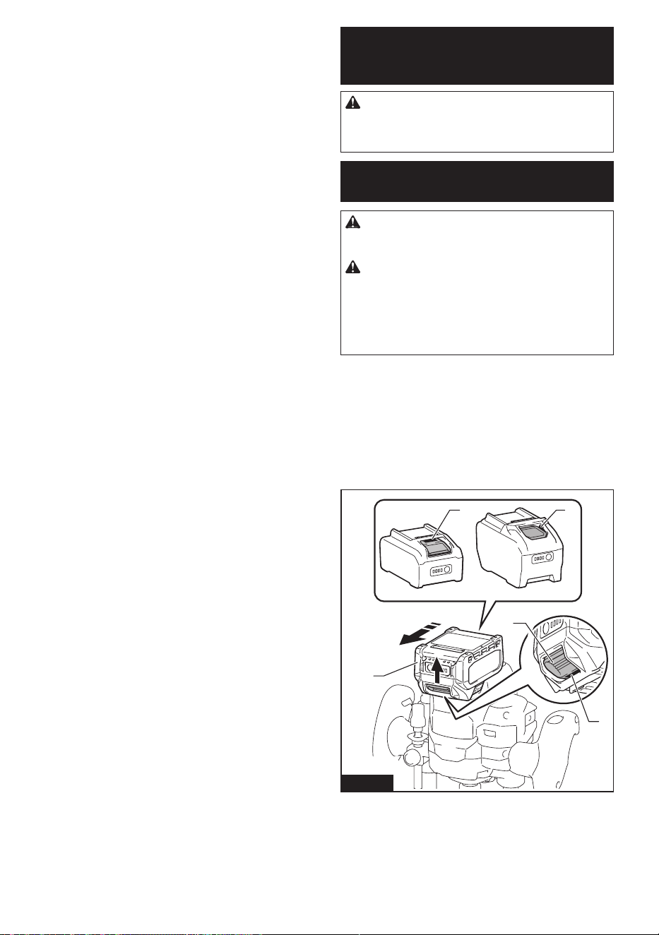
31 ESPAÑOL
8. No opere la unidad inalámbrica en lugares con
alta temperatura o donde pueda generarse
electricidad estática o ruido eléctrico.
9. La unidad inalámbrica puede producir campos
electromagnéticos (CEM), sin embargo éstos
no son dañinos para el usuario.
10. La unidad inalámbrica es un instrumento de
precisión. Tenga cuidado de no dejar caer ni
golpear la unidad inalámbrica.
11.
Evite tocar la terminal de la unidad inalámbrica con
las manos descubiertas o con materiales metálicos.
12. Retire siempre la batería del producto al insta-
lar en él la unidad inalámbrica.
13.
Cuando abra la tapa de la ranura, evite el lugar donde
el polvo y el agua puedan introducirse en la ranura.
Mantenga siempre la entrada de la ranura limpia.
14. Inserte siempre la unidad inalámbrica en la
dirección correcta.
15.
No oprima el botón de activación inalámbrica en
la unidad inalámbrica demasiado fuerte, ni lo haga
con ningún objeto que tenga un borde loso.
16. Cierre siempre la tapa de la ranura durante la
operación.
17. No retire la unidad inalámbrica de la ranura
mientras se esté suministrando energía a la
herramienta. El hacerlo podría causar una avería
de la unidad inalámbrica.
18. No retire la etiqueta en la unidad inalámbrica.
19.
No coloque ninguna etiqueta en la unidad inalámbrica.
20. No deje la unidad inalámbrica en un lugar
donde pueda generarse electricidad estática o
ruido eléctrico.
21. No deje la unidad inalámbrica en un lugar
sujeto a temperaturas altas, tal como un vehí-
culo estacionado bajo el sol.
22. No deje la unidad inalámbrica en un lugar
donde haya polvo o suciedad ni en un lugar
donde pueda generarse gas corrosivo.
23. Los cambios repentinos de temperatura
podrían humedecer la unidad inalámbrica. No
utilice la unidad inalámbrica hasta que la con-
densación se haya secado por completo.
24. Cuando vaya a limpiar la unidad inalámbrica,
hágalo cuidadosamente usando un paño
suave seco. No utilice bencina, disolvente,
grasa conductora o sustancias similares.
25. Cuando vaya a almacenar la unidad inalám-
brica, guárdela en el estuche suministrado o
en un contenedor libre de electricidad estática.
26. No inserte ningún otro dispositivo que no sea
la unidad inalámbrica de Makita en la ranura de
la herramienta.
27. No utilice la herramienta si la tapa de la ranura
está dañada. La entrada de agua, polvo o sucie-
dad en la ranura podría causar una avería.
28. No jale ni tuerza la tapa de la ranura más de
lo necesario. Vuelva a colocar la tapa si ésta se
sale de la herramienta.
29. Reemplace la tapa de la ranura si llega a per-
derse o dañarse.
GUARDE ESTAS
INSTRUCCIONES.
DESCRIPCIÓN DEL
FUNCIONAMIENTO
PRECAUCIÓN: Asegúrese siempre de que la
herramienta esté apagada y el cartucho de batería
haya sido extraído antes de realizar cualquier
ajuste o comprobación en la herramienta.
Instalación o extracción del
cartucho de batería
PRECAUCIÓN: Apague siempre la herra-
mienta antes de colocar o quitar el cartucho de
batería.
PRECAUCIÓN: Sujete la herramienta y el car-
tucho de la batería con rmeza al colocar o quitar
el cartucho de batería. Si no se sujeta con rmeza la
herramienta y el cartucho de batería, puede ocasio-
nar que se resbalen de sus manos causando daños
a la herramienta y al cartucho de batería, así como
lesiones a la persona.
Para instalar el cartucho de batería, alinee la lengüeta
sobre el cartucho de batería con la ranura en la carcasa
y deslícela hasta su lugar. Insértelo por completo hasta
que se je en su lugar con un pequeño clic. Si puede
ver el indicador rojo como se muestra en la ilustración,
este no ha quedado asegurado por completo.
Para quitar el cartucho de batería, deslícelo de la herra-
mienta mientras desliza el botón sobre la parte delan-
tera del cartucho.
1
2
3
1
1
Fig.1
► 1. Indicador rojo 2. Botón 3. Cartucho de batería
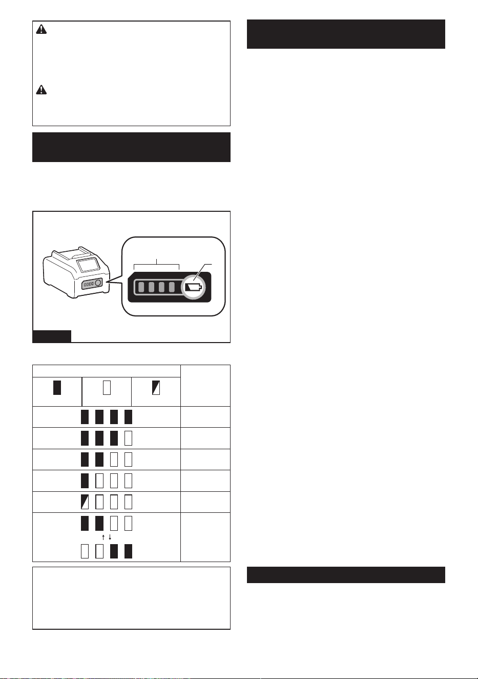
32 ESPAÑOL
PRECAUCIÓN: Introduzca siempre com-
pletamente el cartucho de batería hasta que
el indicador rojo no pueda verse. Si no, podría
accidentalmente salirse de la herramienta y caer al
suelo causando una lesión a usted o alguien a su
alrededor.
PRECAUCIÓN: No instale el cartucho de
batería a la fuerza. Si el cartucho no se desliza al
interior fácilmente, se debe a que no está siendo
insertado correctamente.
Indicación de la capacidad restante
de la batería
Oprima el botón de vericación en el cartucho de la
batería para que indique la capacidad restante de la
batería. Las luces indicadoras se iluminarán por algu-
nos segundos.
1
2
Fig.2
► 1. Luces indicadoras 2. Botón de vericación
Luces indicadoras Capacidad
restante
Iluminadas Apagadas Parpadeando
75% a 100%
50% a 75%
25% a 50%
0% a 25%
Cargar la
batería.
La batería
pudo haber
funcionado
mal.
NOTA: Dependiendo de las condiciones de uso y
la temperatura ambiente, la indicación podrá diferir
ligeramente de la capacidad real.
NOTA: La primera luz indicadora (extrema izquierda)
parpadeará cuando el sistema de protección de
batería esté en funcionamiento.
Sistema de protección para la
herramienta/batería
La herramienta está equipada con un sistema de pro-
tección de la herramienta/batería. Este sistema corta
en forma automática el suministro de energía al motor
para prolongar la vida útil de la herramienta y la batería.
La herramienta se detendrá automáticamente durante
la operación si la herramienta o la batería se someten a
una de las siguientes condiciones:
Protección contra sobrecarga
Cuando la herramienta/batería sean utilizadas de
una manera que cause que consuman una cantidad
inusualmente alta de corriente, la herramienta se
detendrá automáticamente. En este caso, apague la
herramienta y detenga la aplicación que causó que la
herramienta se sobrecargara. Luego encienda la herra-
mienta para reiniciarla.
Protección contra
sobrecalentamiento
Cuando la herramienta o la batería se sobrecalienten,
la herramienta se detendrá automáticamente y las
lámparas parpadearán. En este caso, apague la herra-
mienta presionando el botón de bloqueo/desbloqueo,
quitando la batería o dejando la herramienta durante 60
segundos sin realizar ninguna operación. Permita que
la herramienta y la batería se enfríen antes de volver a
encender la herramienta.
Protección en caso de
sobredescarga
Cuando la capacidad de la batería no es suciente, la
herramienta se detiene automáticamente. En este caso,
retire la batería de la herramienta y cárguela.
Protección contra otras causas
El sistema de protección también está diseñado para
otras causas que podrían dañar la herramienta, y per-
mite que la herramienta se detenga automáticamente.
Siga todos los pasos a continuación para eliminar las
causas cuando la herramienta se haya detenido tempo-
ralmente o se haya detenido durante el funcionamiento.
1. Apague la herramienta, y luego enciéndala nueva-
mente para reiniciarla.
2. Cargue la(s) batería(s) o reemplácela(s) con
batería(s) recargada(s).
3. Deje que la herramienta y la(s) batería(s) se
enfríen.
Si no hay ninguna mejora al restaurar el sistema de
protección, comuníquese con su centro local de servi-
cio Makita.
Accionamiento del interruptor
Para encender la herramienta, oprima el botón de
bloqueo/desbloqueo. La herramienta se pondrá en el
modo en espera. Para arrancar la herramienta, jale el
gatillo interruptor en el modo en espera. Para detener la
herramienta, suelte el gatillo interruptor y la herramienta
pasará al modo de espera. Para apagar la herramienta,
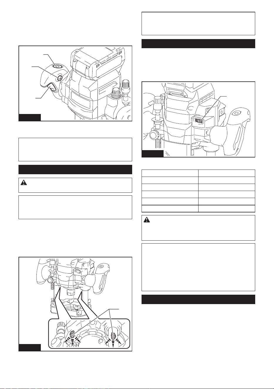
33 ESPAÑOL
oprima el botón de bloqueo/desbloqueo en el modo en
espera.
Para una operación continua, jale el gatillo interruptor
y oprima el botón de bloqueo. Tire del gatillo interruptor
nuevamente para cancelar la operación continua, y
suelte el gatillo interruptor para detener la herramienta.
1
3
2
Fig.3
► 1. Botón de bloqueo/desbloqueo 2. Botón de blo-
queo 3. Gatillo interruptor
NOTA: Si la herramienta permanece 5 segundos sin
ninguna operación en el modo de espera o 5 segun-
dos después de soltar el gatillo interruptor, la herra-
mienta se apagará automáticamente.
Encendido de las lámparas
PRECAUCIÓN: No mire a la luz ni vea a la
fuente de luz directamente.
AVISO: Cuando la herramienta se sobrecaliente,
la lámpara parpadeará. Permita que la herra-
mienta se enfríe por completo antes de volver a
usarla.
Para encender las lámparas, oprima el botón de blo-
queo/desbloqueo. Las lámparas permanecen encendi-
das durante el funcionamiento. Las lámparas se apaga-
rán cuando la herramienta permanece 5 segundos sin
ninguna operación en el modo de espera o 5 segundos
después de soltar el gatillo interruptor.
1
Fig.4
► 1. Luz
NOTA: Utilice un paño seco para quitar la suciedad
de la lente de la lámpara. Tenga cuidado de no rayar
la lente de la lámpara ya que la iluminación podría
disminuir.
Selector de ajuste de velocidad
La velocidad de rotación de la herramienta se puede
cambiar girando el selector de ajuste de velocidad. La
tabla a continuación muestra el número en el selec-
tor de ajuste de velocidad y la velocidad de rotación
correspondiente.
1
Fig.5
► 1. Selector de ajuste de velocidad
Número Velocidad
1 8 000 r/min
2 12 500 r/min
3 17 000 r/min
4 21 000 r/min
5 25 000 r/min
PRECAUCIÓN: No cambie la velocidad de
rotación durante el funcionamiento. De lo contra-
rio, una reacción inesperada de la herramienta podría
provocar lesiones.
AVISO: Si la herramienta es operada a baja velo-
cidad de forma continua durante un tiempo pro-
longado, el motor se sobrecargará provocando
que la herramienta se averíe.
AVISO: El selector de ajuste de velocidad solo
puede girarse hasta 5 y de regreso a 1. No lo
fuerce más allá de 5 o 1 o la función de ajuste de
velocidad podría dejar de funcionar.
Funcionamiento electrónico
La herramienta está equipada con funciones electróni-
cas para facilitar la operación.
• Control de velocidad constante
La función de control de velocidad permite una
rotación constante independientemente de las
condiciones de carga.
• Arranque suave
La función de arranque suave minimiza el impacto
de encendido y hace que la herramienta se ponga
en marcha suavemente.
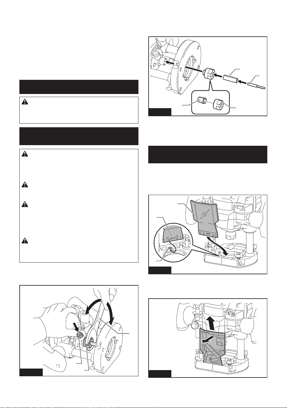
34 ESPAÑOL
• Freno suave
La herramienta se detiene suavemente con el
freno suave. El freno suave evita daños a la
pieza de trabajo debido al retroceso, y le permite
comenzar la siguiente operación antes.
Si de manera consistente la herramienta no logra
detener la fresa de la rebajadora después de
que se apaga el interruptor, lleve la herramienta
a un centro de servicio Makita para que le den
mantenimiento.
MONTAJE
PRECAUCIÓN: Asegúrese siempre de que la
herramienta esté apagada y el cartucho de batería
haya sido extraído antes de realizar cualquier
trabajo en la misma.
Instalación o extracción de la fresa
de la rebajadora
PRECAUCIÓN: Instale la fresa de la rebaja-
dora rmemente. Siempre utilice únicamente la
llave provista con la herramienta. Una fresa de la
rebajadora oja o demasiado apretada puede ser
peligrosa.
PRECAUCIÓN: Utilice siempre un cono de
sujeción que sea adecuado para el diámetro del
vástago de la fresa de la rebajadora.
PRECAUCIÓN: No apriete la tuerca de
sujeción sin insertar una fresa de la rebajadora
ni instale una fresa de la rebajadora de vástago
pequeño sin utilizar un manguito de sujeción.
Tanto lo uno como lo otro puede producir la rotura del
cono de sujeción.
PRECAUCIÓN: Utilice únicamente fresas
de la rebajadora cuya velocidad máxima, como
se indica en la fresa de la rebajadora, exceda la
velocidad máxima de la rebajadora.
Inserte la fresa de la rebajadora hasta el fondo en el
cono de sujeción. Presione el bloqueo del eje y apriete
la tuerca de sujeción con la llave.
1
2
3
4
5
Fig.6
► 1. Bloqueo de eje 2. Aojar 3. Apretar 4. Llave
5. Tuerca de sujeción
Cuando utilice fresas de la rebajadora con vástago de
diámetro más pequeño, primero inserte el manguito
de sujeción apropiado en el cono de sujeción y luego
instale la fresa de la rebajadora.
1
2
4
3
Fig.7
► 1. Cono de sujeción 2. Tuerca de sujeción
3. Manguito de sujeción 4. Fresa de la rebajadora
Para extraer la fresa de la rebajadora, siga el procedi-
miento de instalación en orden inverso.
Instalación o extracción del
deector de astillas
Accesorio opcional
Para instalar el deector de astillas, insértelo en una
ranura, alineando el oricio del deector de astillas con
la protuberancia.
1
3
2
Fig.8
► 1. Deector de astillas 2. Oricio 3. Protuberancia
Para retirar el deector de astillas, incline la parte supe-
rior del deector de astillas hacia adelante y extráigalo.
Fig.9
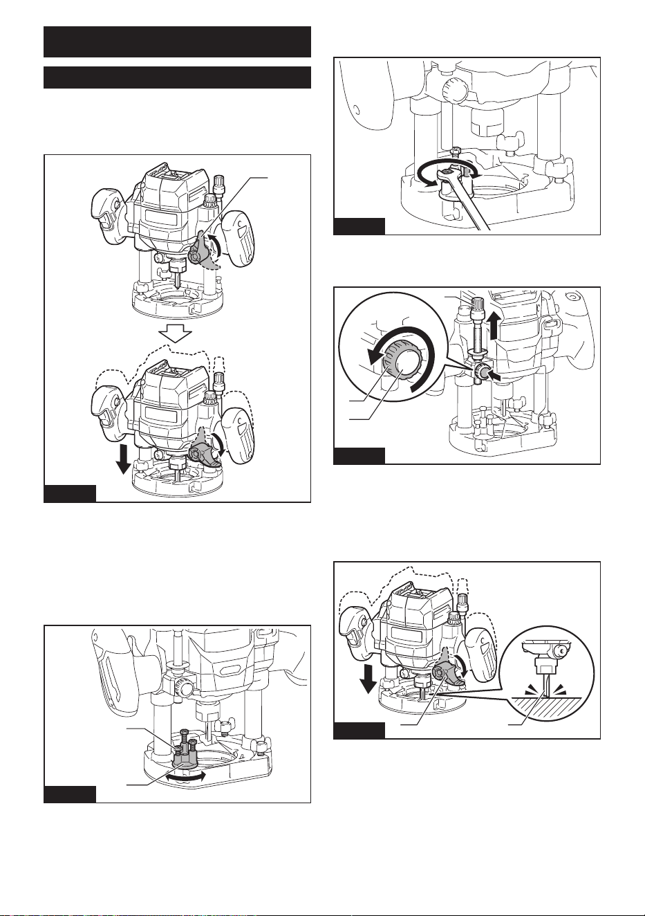
35 ESPAÑOL
OPERACIÓN
Ajuste de la profundidad de corte
Para ajustar la profundidad de corte, suelte la palanca
de bloqueo y luego baje el cuerpo. Después del ajuste,
gire rmemente la palanca de bloqueo para asegurar
el cuerpo.
1
Fig.10
► 1. Palanca de bloqueo
Ajuste de la profundidad de corte
con el tornillo del tope
1. Coloque la herramienta sobre una supercie
plana.
2. Elija el tornillo de tope girando la base de tope.
1
2
Fig.11
► 1. Tornillo de tope 2. Base de tope
Para ajustar la altura de los tornillos del tope, utilice la
llave o el destornillador.
Fig.12
3. Aoje la tuerca de jación, luego jale hacia
arriba la barra de tope mientras oprime el botón de
alimentación.
1
2
3
Fig.13
► 1. Barra de tope 2. Tuerca de jación 3. Botón de
alimentación
4. Suelte la palanca de bloqueo, empuje la herra-
mienta hacia abajo hasta que la punta de la fresa de
la rebajadora toque la supercie plana, y luego gire la
palanca de bloqueo para asegurar la herramienta.
21
Fig.14
► 1. Palanca de bloqueo 2. Fresa de la rebajadora
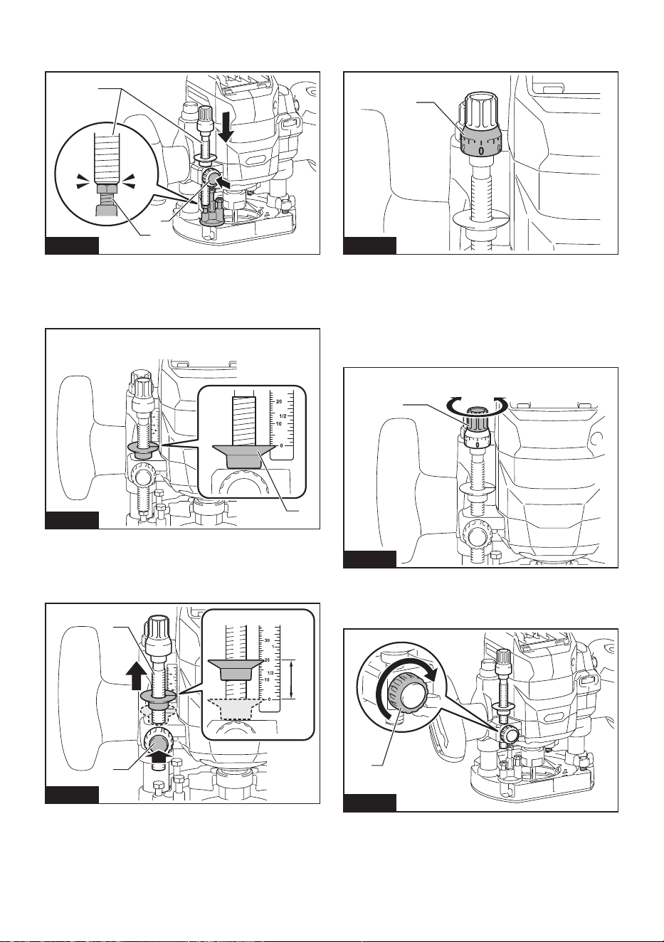
36 ESPAÑOL
5. Presione hacia abajo la barra de tope mientras
oprime el botón de alimentación hasta que éste haga
contacto con el tornillo de tope.
1
3
2
Fig.15
► 1. Barra de tope 2. Tornillo de tope 3. Botón de
alimentación
6. Deslice el indicador de profundidad de manera
que éste indique “0” en la escala.
1
Fig.16
► 1. Indicador de profundidad
7. Ajuste la profundidad de corte jalando hacia
arriba la barra de tope mientras oprime el botón de
alimentación.
1
2
3
Fig.17
► 1. Barra de tope 2. Botón de alimentación
3. Profundidad de corte
8. Para realizar un ajuste no de la profundidad de
corte, gire el selector en la barra de tope de manera
que éste indique “0”.
1
Fig.18
► 1. Selector
9. Gire la cabeza de la barra de tope para lograr la
profundidad deseada. Para aumentar la profundidad,
gire la cabeza en sentido inverso al de las manecillas
del reloj. Para reducir la profundidad, gire la cabeza en
el sentido de las manecillas del reloj. (La profundidad
cambia en 1 mm (3/64″) por una revolución).
1
Fig.19
► 1. Cabeza de la barra de tope
10. Apriete la tuerca de jación para asegurar la barra
de tope.
1
Fig.20
► 1. Tuerca de jación
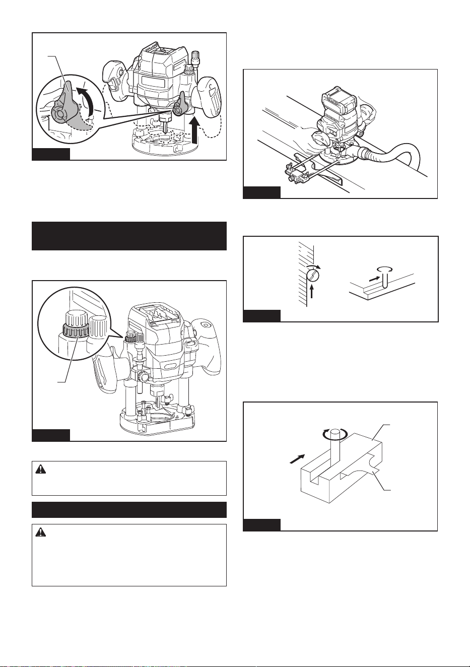
37 ESPAÑOL
11. Libere la palanca de bloqueo.
1
Fig.21
► 1. Palanca de bloqueo
Si empuja la herramienta hacia abajo hasta que la barra
de tope se encuentre con el tornillo de tope, puede
lograr la profundidad de corte que ajustó mediante el
procedimiento anterior.
Ajuste del límite superior del cuerpo
de la herramienta
El límite superior del cuerpo de la herramienta puede
ser ajustado girando la tuerca de nailon.
1
Fig.22
► 1. Tuerca de nailon
PRECAUCIÓN: No baje demasiado la tuerca
de nailon. La fresa de la rebajadora sobresaldrá
peligrosamente.
Operación general
PRECAUCIÓN: Antes de la operación, asegú-
rese siempre de que el cuerpo de la herramienta
se eleve automáticamente hasta el límite superior
y que la fresa de la rebajadora no sobresalga
de la base de la herramienta cuando se aoje la
palanca de bloqueo.
1. Coloque la base sobre la pieza de trabajo a cortar
sin que la fresa de la rebajadora haga contacto alguno.
2. Encienda la herramienta y espere hasta que la
fresa de la rebajadora adquiera plena velocidad.
3. Baje el cuerpo de la herramienta y mueva la
herramienta hacia adelante sobre la supercie de
la pieza de trabajo, manteniendo la base a ras y
avanzando suavemente hasta que el corte haya sido
completado.
Fig.23
Cuando realice cortes de bordes, la supercie de la
pieza de trabajo deberá estar en el costado izquierdo
de la fresa de la rebajadora en la dirección de avance.
4
4
3
1
2
2
Fig.24
► 1. Pieza de trabajo 2. Dirección de rotación de la
fresa 3. Vista desde la parte superior de la herra-
mienta 4. Dirección de avance
Al usar la guía recta o la guía de recorte, asegúrese
de mantenerla sobre el costado derecho respecto a la
dirección de alimentación. Esto ayudará a mantenerla
al ras con el costado de la pieza de trabajo.
1
2
4
3
Fig.25
► 1. Dirección de avance 2. Dirección de rotación de
la fresa 3. Pieza de trabajo 4. Guía recta
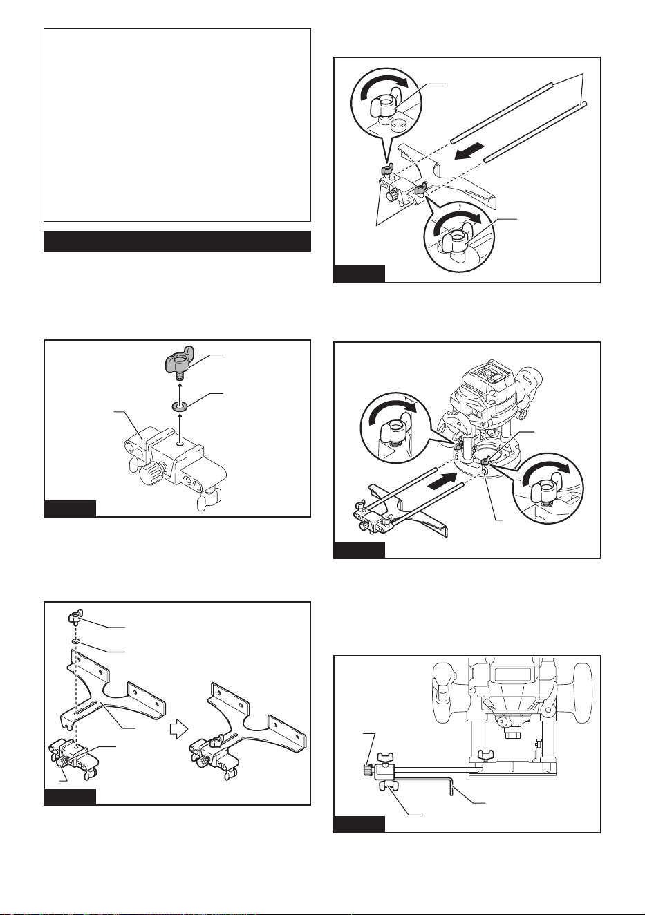
38 ESPAÑOL
NOTA: Si mueve la herramienta hacia adelante
demasiado rápido, podrá obtener un corte de mala
calidad, o dañar la fresa de la rebajadora o el motor.
Si mueve la herramienta hacia adelante demasiado
despacio, podrá quemar y arruinar el corte.
La velocidad de avance apropiada dependerá del
tamaño de la fresa de la rebajadora, el tipo de pieza
de trabajo y la profundidad de corte.
Antes de comenzar el corte en la pieza de trabajo
real, haga un corte de muestra en un trozo de madera
de desecho para considerar la velocidad de avance
adecuada.
También puede conrmar la conguración de la fresa
de la rebajadora midiendo el corte de muestra.
Uso de la guía recta
Accesorio opcional
La guía recta resulta útil para hacer un corte recto
cuando se realiza biselado o ranurado.
1. Retire el tornillo de jación y la arandela del suje-
tador de la guía.
1
2
3
Fig.26
► 1. Sujetador de la guía 2. Tornillo de jación
3. Arandela
2. Aoje el tornillo de ajuste para hacer una ranura.
Coloque la guía recta en la ranura, luego monte la
arandela y apriete el tornillo de jación.
1
5
4
3
2
Fig.27
► 1. Tornillo de ajuste 2. Muesca 3. Guía recta
4. Arandela 5. Tornillo de jación
3. Monte la barra 8 en las ranuras en el sujetador de
la guía, y apriete los tornillos de jación.
1
3
2
3
Fig.28
► 1. Barra 8 2. Ranura 3. Tornillo de jación
4. Instale la guía recta en las ranuras de la base de
la herramienta, y luego apriete los tornillos de sujeción.
1
2
Fig.29
► 1. Ranura 2. Tornillo de jación
5. Aoje el tornillo de sujeción y ajuste la distancia
entre la fresa de la rebajadora y la guía recta girando el
tornillo de ajuste (1,5 mm (1/16″) por giro). En la distan-
cia deseada, apriete el tornillo de jación para asegurar
la guía recta.
2
1
3
Fig.30
► 1. Tornillo de jación 2. Tornillo de ajuste 3. Guía
recta
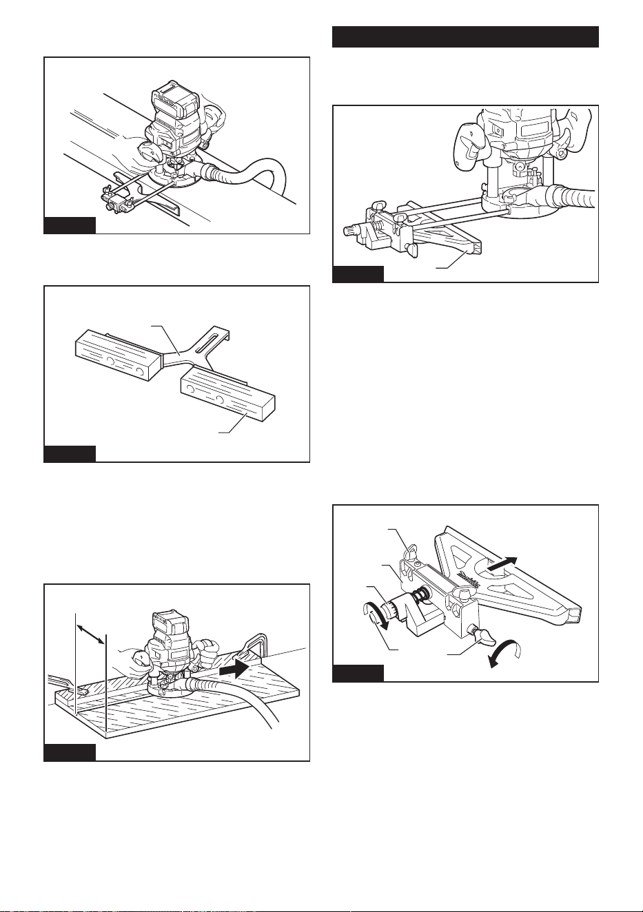
39 ESPAÑOL
6. Desplace la herramienta con la guía recta a ras
con el lado de la pieza de trabajo.
Fig.31
Se podrá hacer una guía recta más ancha de las
dimensiones deseadas utilizando los oricios apropia-
dos en la guía para atornillar piezas extra de madera.
1
2
Fig.32
► 1. Madera 2. Guía recta
Si la distancia (A) entre el costado de la pieza de tra-
bajo y la posición de corte es muy ancha para la guía
recta, o si el costado de la pieza de trabajo no es recto,
no podrá utilizarse la guía recta.
En este caso, sujete rmemente una tabla recta a la
pieza de trabajo y utilícela como guía contra la base.
Avance la herramienta en la dirección de la echa.
A
Fig.33
Uso de la guía recta de ajuste no
Accesorio opcional
La guía recta de ajuste no puede ajustar la distancia
con mayor precisión que la guía recta.
1
Fig.34
► 1. Guía recta de ajuste no
1. Monte la barra 8 en las ranuras en el sujetador
de la guía, y apriete el tornillo de mariposa (5 mm x 14
mm).
2. Instale la guía recta de ajuste no a la base de la
herramienta. Apriete los tornillos de jación en la base
de la herramienta.
3. Aoje el tornillo de mariposa (6 mm x 50 mm) y
ajuste la distancia entre la fresa de la rebajadora y la
guía recta girando el tornillo de ajuste (1 mm (3/64″)
por giro). En la distancia deseada, apriete el tornillo de
mariposa (6 mm x 50 mm) para asegurar la guía recta.
El anillo de escala se puede girar por separado del
tornillo de ajuste, de modo que la unidad de escala se
pueda alinear a cero (0).
2
1
3
4
5
Fig.35
► 1. Tornillo de ajuste 2. Tornillo de mariposa (6 mm
x 50 mm) 3. Tornillo de mariposa (5 mm x 14 mm)
4. Sujetador de la guía 5. Anillo de la escala
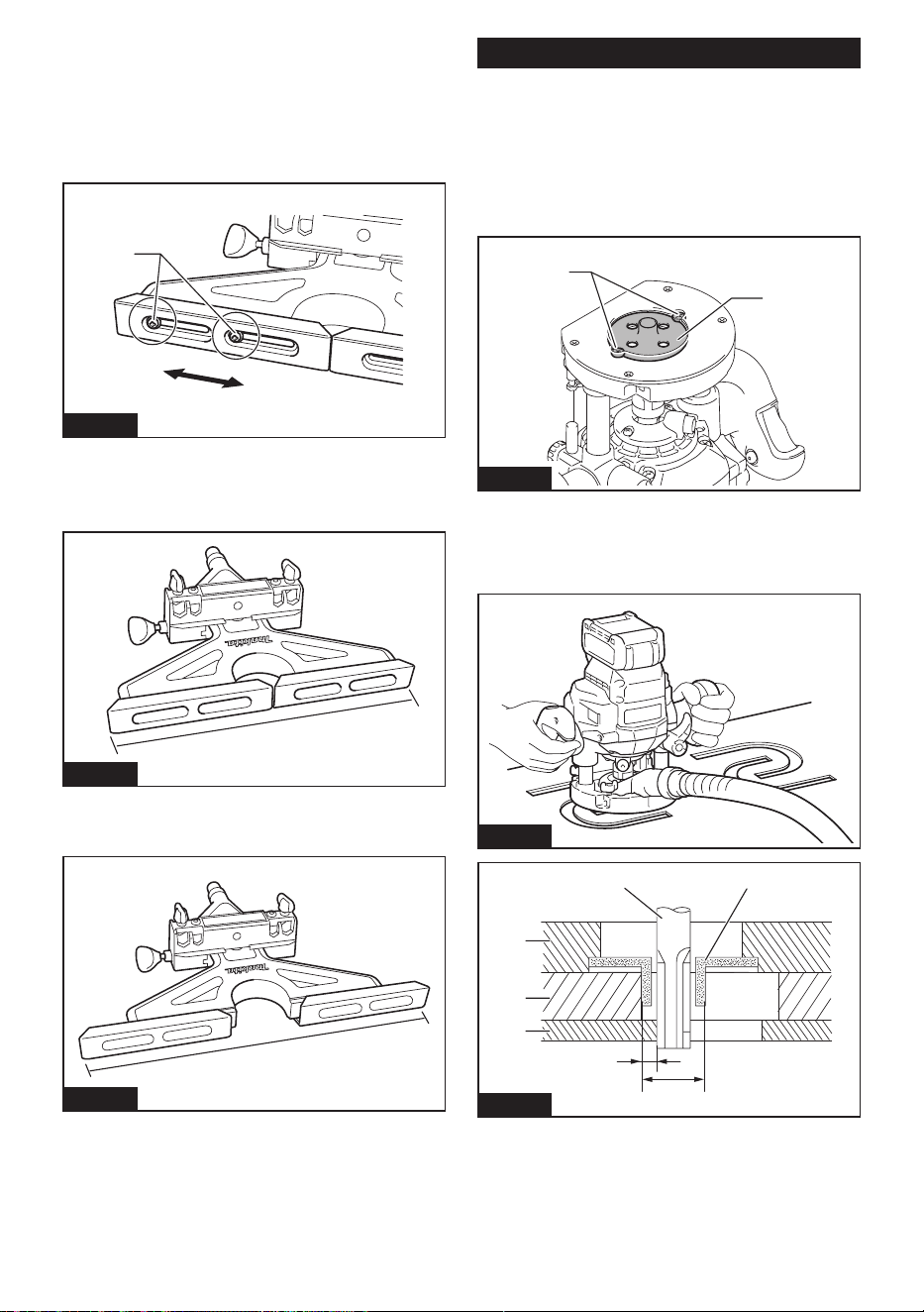
40 ESPAÑOL
Ajuste del ancho de la zapata de la
guía
La zapata de la guía es ajustable en el rango de 280
mm a 350 mm (11″ a 13-3/4″).
1. Aoje los tornillos, y mueva el ancho de la zapata
de la guía para ajustar.
1
Fig.36
► 1. Tornillo
2. Después de ajustar el ancho, apriete los tornillos.
Anchura mínima de abertura
1
Fig.37
► 1. 280 mm (11″)
Anchura máxima de abertura
1
Fig.38
► 1. 350 mm (13-3/4″)
Uso de la guía de plantilla
Accesorio opcional
La guía de plantilla permite repetir un corte con los
patrones de plantilla mediante el uso de una plantilla.
1. Aoje los tornillos de la base de la herramienta, y
retírelos.
2. Coloque la guía de plantilla sobre la base y luego
apriete los tornillos.
1
2
Fig.39
► 1. Guía de plantilla 2. Tornillo
3. Ponga la herramienta sobre la plantilla y mueva
la herramienta, de manera que la guía de plantilla se
deslice a lo largo del costado de la plantilla.
Fig.40
17
6
5
2
3
4
Fig.41
► 1. Fresa de la rebajadora 2. Base 3. Plantilla
4. Pieza de trabajo 5. Distancia (X) 6. Diámetro
exterior de la guía de plantilla 7. Guía de plantilla
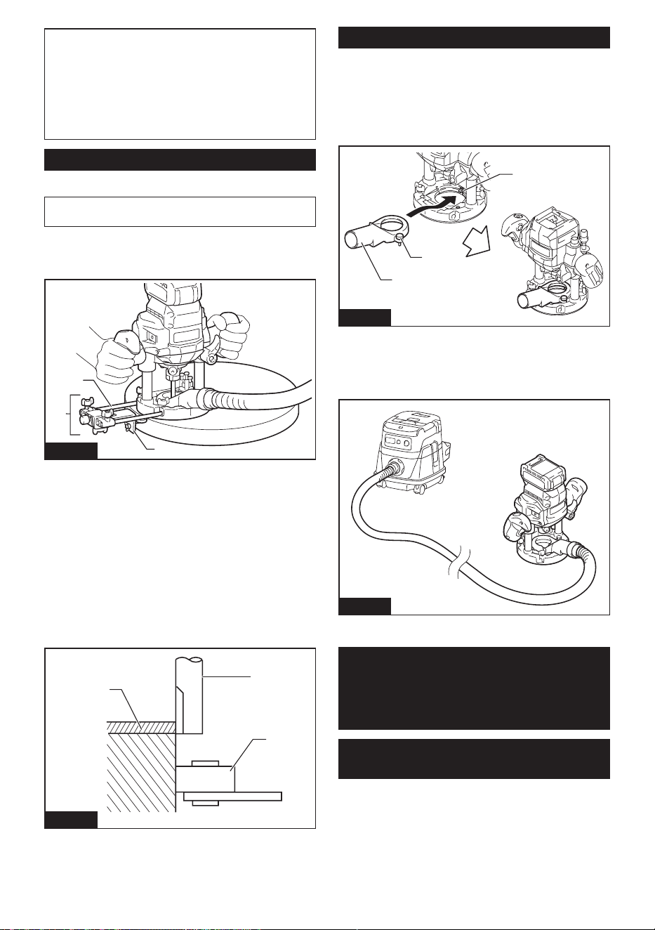
41 ESPAÑOL
NOTA: La pieza de trabajo será cortada con un
tamaño ligeramente diferente al de la plantilla.
Permita que haya una distancia (X) entre la fresa de
la rebajadora y el exterior de la guía de plantilla. La
distancia (X) se puede calcular utilizando la siguiente
ecuación:
Distancia (X) = (diámetro exterior de la guía de planti-
lla - diámetro de la fresa de la rebajadora) / 2
Uso de la guía de recorte
Accesorio opcional
NOTA: Cuando se utiliza la guía de recorte, también
se requieren la barra 8 y el sujetador de la guía.
La guía de recorte permite hacer los cortes curvados
como chapas para muebles moviendo el rodillo guía a
lo largo del costado de la pieza de trabajo.
1
2
3
Fig.42
► 1. Guía de recorte 2. Barra 8 3. Sujetador de la guía
1. Instale la guía de recorte y las barras al sujetador
de la guía.
2. Inserte las barras en las ranuras en el sujetador
de la guía, y apriete el tornillo de jación.
3. Aoje el tornillo de sujeción y ajuste la distancia
entre la fresa de la rebajadora y la guía de recorte
girando el tornillo de ajuste (1,5 mm (1/16″) por giro).
En la distancia deseada, apriete el tornillo de jación
para jar la guía de recorte.
4. Mueva la herramienta desplazando el rodillo guía
a lo largo del costado de la pieza de trabajo.
3
2
1
Fig.43
► 1. Fresa de la rebajadora 2. Rodillo guía 3. Pieza
de trabajo
Boquilla para polvo
La instalación de la boquilla para polvo permite conec-
tar una aspiradora Makita a la herramienta.
1. Instale la boquilla para polvo en la base de la
herramienta usando el tornillo de mariposa, de modo
que la protuberancia de la boquilla para polvo encaje en
la muesca de la base de la herramienta.
1
3
2
Fig.44
► 1. Boquilla para polvo 2. Tornillo de mariposa
3. Muesca
2. Conecte una aspiradora Makita a la boquilla para
polvo.
Fig.45
FUNCIÓN DE
ACTIVACIÓN
INALÁMBRICA
Lo que puede hacer con la función
de activación inalámbrica
La función de activación inalámbrica permite una ope-
ración limpia y cómoda. Si conecta a la herramienta
una aspiradora compatible, podrá hacer que ésta
funcione automáticamente al activar el interruptor de la
herramienta.
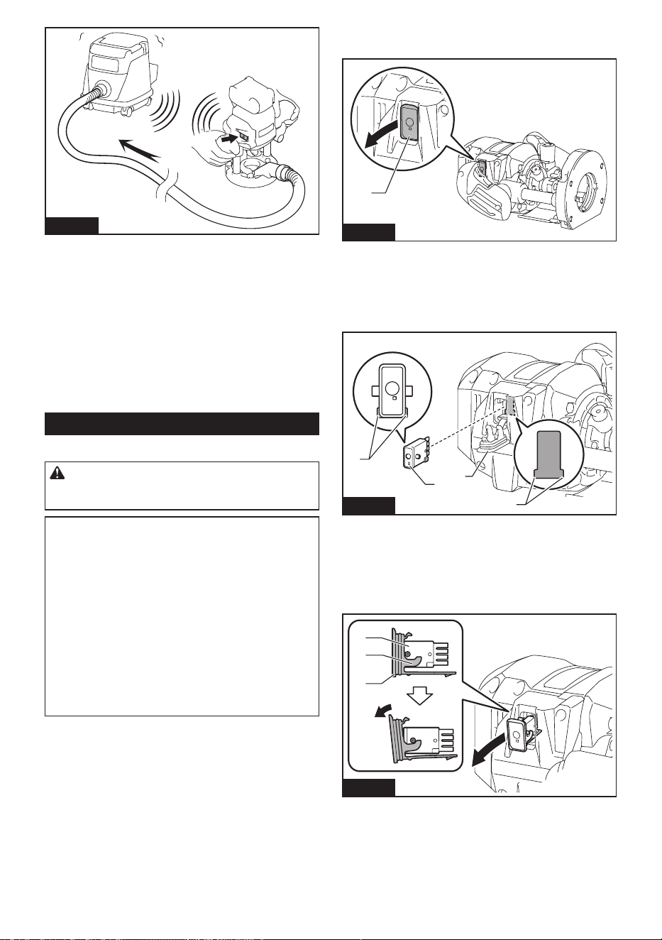
42 ESPAÑOL
Fig.46
Para hacer uso de la función de activación inalámbrica,
tenga preparado lo siguiente:
• Una unidad inalámbrica (accesorios opcionales)
• Una aspiradora compatible con la función de
activación inalámbrica
A continuación se presenta la descripción general del
ajuste de la función de activación inalámbrica. Consulte
cada sección para ver los procedimientos a detalle.
1. Instalación de la unidad inalámbrica
2. Registro de la herramienta para la aspiradora
3. Inicio de la función de activación inalámbrica
Instalación de la unidad inalámbrica
Accesorio opcional
PRECAUCIÓN: Coloque la herramienta sobre
una supercie plana y estable cuando vaya a
instalar la unidad inalámbrica.
AVISO: Limpie el polvo y la suciedad en la herra-
mienta antes de instalar la unidad inalámbrica.
El polvo o la suciedad podrían causar una avería
si llegan a introducirse en la ranura de la unidad
inalámbrica.
AVISO: Para evitar una avería a causa de la elec-
tricidad estática, toque un material de descarga
de electricidad estática, tal como una pieza metá-
lica de la herramienta antes de levantar la unidad
inalámbrica.
AVISO: Cuando vaya a instalar la unidad inalám-
brica, asegúrese siempre de que ésta sea inser-
tada en la dirección correcta y que la tapa esté
completamente cerrada.
1. Abra la tapa en la herramienta tal como se mues-
tra en la ilustración.
1
Fig.47
► 1. Tapa
2. Inserte la unidad inalámbrica en la ranura y luego
cierre la tapa.
Cuando inserte la unidad inalámbrica, alinee las partes
salientes con las partes cóncavas en la ranura.
1
2
3
4
Fig.48
► 1. Unidad inalámbrica 2. Parte saliente 3. Tapa
4. Parte cóncava
Cuando extraiga la unidad inalámbrica, abra la tapa
lentamente. Los ganchos en la parte posterior de la
tapa levantarán la unidad inalámbrica mientras usted
jala hacia arriba la tapa.
1
2
3
Fig.49
► 1. Unidad inalámbrica 2. Gancho 3. Tapa
Una vez extraída la unidad inalámbrica, guárdela en el
estuche suministrado o en un contenedor libre de elec-
tricidad estática.
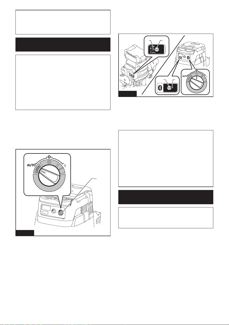
43 ESPAÑOL
AVISO: Use siempre los ganchos en la parte
posterior de la tapa cuando extraiga la unidad
inalámbrica. Si los ganchos no sujetan la unidad
inalámbrica, cierre la tapa por completo y vuelva a
abrirla lentamente.
Registro de la herramienta para la
aspiradora
NOTA: Para el registro de la herramienta, se requiere
una aspiradora Makita compatible con la función de
activación inalámbrica.
NOTA: Termine de instalar la unidad inalámbrica en
la herramienta antes de comenzar con el registro de
la herramienta.
NOTA: Durante el registro de la herramienta, no jale
el gatillo interruptor ni active el interruptor de encen-
dido en la aspiradora.
NOTA: Consulte también el manual de instrucciones
de la aspiradora.
Si desea activar la aspiradora junto con el interruptor
de la herramienta, termine antes con el registro de la
herramienta.
1. Instale las baterías en la aspiradora y en la
herramienta.
2. Ajuste el interruptor de modo en espera en la aspi-
radora en “AUTO”.
1
Fig.50
► 1. Interruptor de modo en espera
3. Oprima el botón de activación inalámbrica en la
aspiradora durante 3 segundos hasta que la luz indica-
dora de activación inalámbrica parpadee en verde. Y
luego oprima el botón de activación inalámbrica en la
herramienta de la misma manera.
21
12
Fig.51
► 1. Botón de activación inalámbrica 2. Luz indica-
dora de activación inalámbrica
Si la aspiradora y la herramienta han sido conectadas
exitosamente, las luces indicadoras de activación ina-
lámbrica se encenderán en verde durante 2 segundos y
comenzarán a parpadear en azul.
NOTA: Las luces indicadoras de activación inalám-
brica terminarán parpadeando en verde después de
un lapso de 20 segundos. Oprima el botón de acti-
vación inalámbrica en la herramienta mientras la luz
indicadora de activación inalámbrica en la aspiradora
esté parpadeando. Si la luz indicadora de activación
inalámbrica no parpadea en verde, oprima el botón
de activación inalámbrica durante un lapso breve y
vuelva a mantenerlo oprimido.
NOTA: Cuando realice dos o más registros de la
herramienta para una aspiradora, termine el registro
de la herramienta de uno en uno.
Inicio de la función de activación
inalámbrica
NOTA: Termine con el registro de la herramienta para
la aspiradora antes de la activación inalámbrica.
NOTA: Consulte también el manual de instrucciones
de la aspiradora.
Después de registrar una herramienta en la aspiradora,
esta última se activará automáticamente junto con el
interruptor de la herramienta.
1. Instale la unidad inalámbrica en la herramienta.
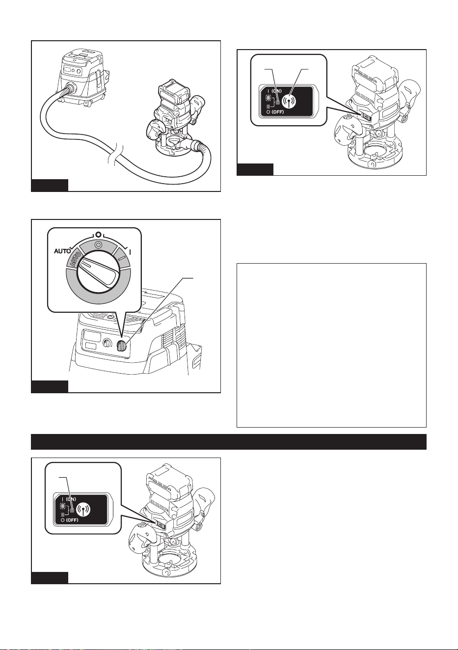
44 ESPAÑOL
2. Conecte la manguera de la aspiradora a la
herramienta.
Fig.52
3. Ajuste el interruptor de modo en espera en la aspi-
radora en “AUTO”.
1
Fig.53
► 1. Interruptor de modo en espera
4. Oprima el botón de activación inalámbrica en la
herramienta durante un lapso breve. La luz indicadora
de activación inalámbrica parpadeará en azul.
2 1
Fig.54
► 1. Botón de activación inalámbrica 2. Luz indica-
dora de activación inalámbrica
5. Encienda la herramienta. Compruebe si la
aspiradora funciona mientras la herramienta está en
funcionamiento.
Para detener la activación inalámbrica de la aspira-
dora, oprima el botón de activación inalámbrica en la
herramienta.
NOTA: La luz indicadora de activación inalámbrica en
la herramienta dejará de parpadear en azul cuando
no haya operación durante 2 horas. En este caso,
ajuste el interruptor de modo en espera en la aspi-
radora en “AUTO” y oprima el botón de activación
inalámbrica en la herramienta nuevamente.
NOTA: La aspiradora funcionará/detendrá con un
retraso. Existirá un desfase cuando la aspiradora
detecte la activación del interruptor de la herramienta.
NOTA: La distancia de transmisión de la unidad
inalámbrica podrá variar en función del lugar y las
circunstancias de los alrededores.
NOTA: Cuando dos o más herramientas estén regis-
tradas en una aspiradora, esta última podrá comen-
zar a funcionar incluso si usted no enciende su herra-
mienta, debido a que otro usuario está utilizando la
función de activación inalámbrica.
Descripción del estado de la luz indicadora de activación inalámbrica
1
Fig.55
► 1. Luz indicadora de activación inalámbrica
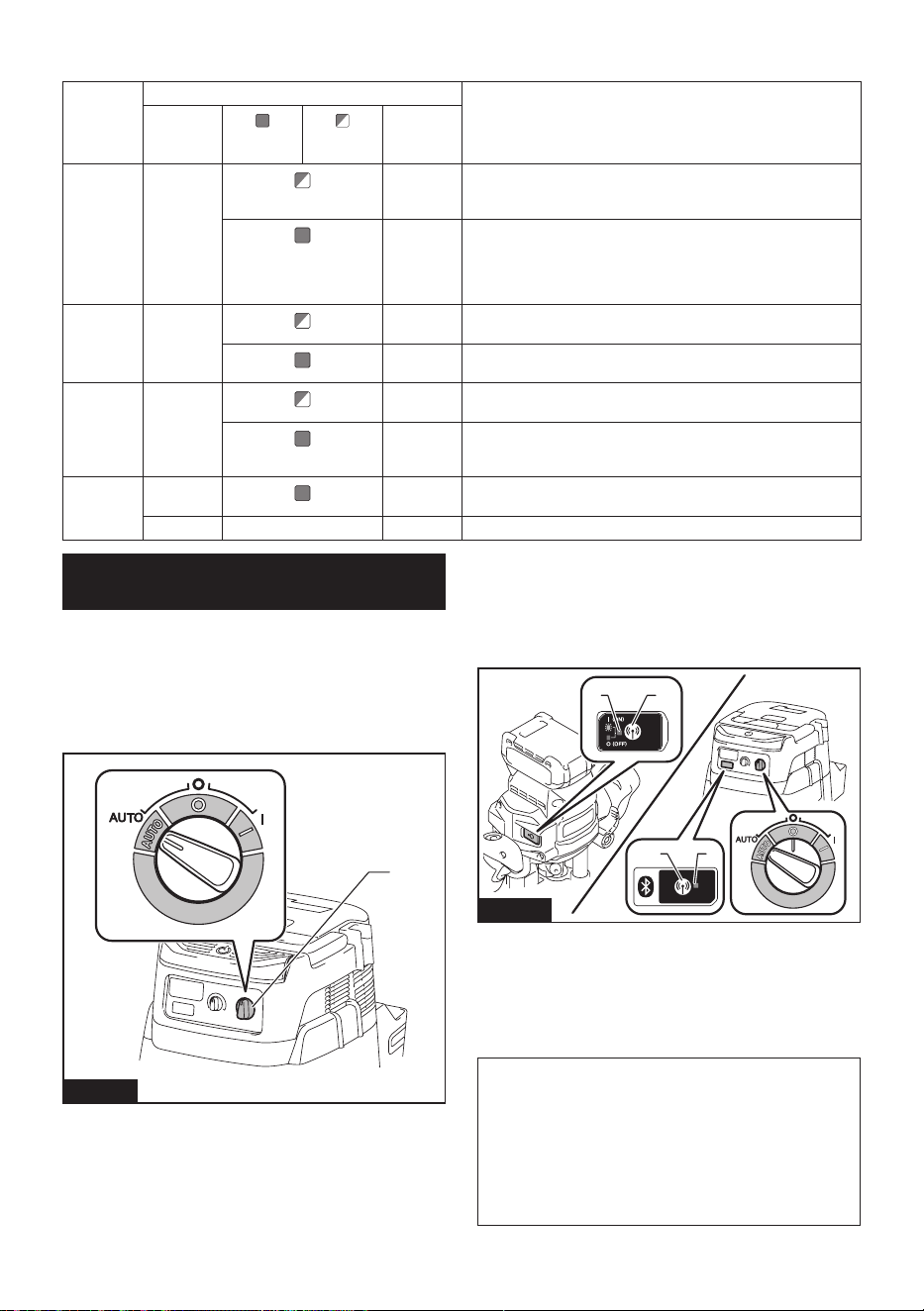
45 ESPAÑOL
La luz indicadora de activación inalámbrica muestra el estado de la función de activación inalámbrica. Consulte la
tabla a continuación para ver qué signica el estado de la luz indicadora.
Estado Luz indicadora de activación inalámbrica Descripción
Color
Encendida
Parpa-
deando
Duración
En espera Azul
2 horas La activación inalámbrica de la aspiradora está disponible. La
luz se apagará automáticamente cuando no se realice ninguna
operación durante 2 horas.
Cuando
la herra-
mienta
está fun-
cionando.
La activación inalámbrica de la aspiradora está disponible y la
herramienta está funcionando.
Registro
de la
herramienta
Verde
20
segundos
Ya se puede realizar el registro de la herramienta. Esperando el
registro por parte de la aspiradora.
2
segundos
El registro de la herramienta ha terminado. La luz indicadora de
activación inalámbrica comenzará a parpadear en azul.
Cancela-
ción del
registro
de la
herramienta
Rojo
20
segundos
Ya se puede cancelar el registro de la herramienta. Esperando la
cancelación por parte de la aspiradora.
2
segundos
La cancelación del registro de la herramienta ha terminado. La
luz indicadora de activación inalámbrica comenzará a parpadear
en azul.
Otros Rojo
3
segundos
La energía es suministrada a la unidad inalámbrica y la función
de activación inalámbrica está arrancando.
Apagada - - La activación inalámbrica de la aspiradora se ha detenido.
Cancelación del registro de la
herramienta para la aspiradora
Realice el siguiente procedimiento para cancelar el
registro de la herramienta para la aspiradora.
1. Instale las baterías en la aspiradora y en la
herramienta.
2. Ajuste el interruptor de modo en espera en la aspi-
radora en “AUTO”.
1
Fig.56
► 1. Interruptor de modo en espera
3. Oprima el botón de activación inalámbrica en la
aspiradora durante 6 segundos. La luz indicadora de
activación inalámbrica parpadeará en verde y luego se
pondrá en rojo. Después de eso, oprima el botón de
activación inalámbrica en la herramienta de la misma
manera.
21
12
Fig.57
► 1. Botón de activación inalámbrica 2. Luz indica-
dora de activación inalámbrica
Si la cancelación se realiza exitosamente, las luces
indicadoras de activación inalámbrica se encenderán
en rojo durante 2 segundos y comenzarán a parpadear
en azul.
NOTA: Las luces indicadoras de activación inalám-
brica terminarán parpadeando en rojo después de un
lapso de 20 segundos. Oprima el botón de activación
inalámbrica en la herramienta mientras la luz indi-
cadora de activación inalámbrica en la aspiradora
esté parpadeando. Si la luz indicadora de activación
inalámbrica no parpadea en rojo, oprima el botón
de activación inalámbrica durante un lapso breve y
vuelva a mantenerlo oprimido.

46 ESPAÑOL
Detección y solución de problemas para la función de activación inalámbrica
Antes de solicitar alguna reparación, primero realice una inspección por su cuenta. Si detecta algún problema que
no esté explicado en el manual, no intente desensamblar la herramienta. En vez de esto, solicite la reparación a un
centro de servicio autorizado de Makita, usando siempre piezas de repuesto Makita.
Estado de la anomalía Causa probable (avería) Remedio
La luz indicadora de activación ina-
lámbrica no enciende/parpadea.
La unidad inalámbrica no está instalada
en la herramienta.
La unidad inalámbrica está instalada
incorrectamente en la herramienta.
Instale la unidad inalámbrica correctamente.
La terminal de la unidad inalámbrica y/o
la ranura está sucia.
Retire con cuidado el polvo y la suciedad en la
terminal de la unidad inalámbrica y limpie la ranura.
El botón de activación inalámbrica en la
herramienta no se ha oprimido.
Oprima el botón de activación inalámbrica en la
herramienta durante un lapso breve.
El interruptor de modo en espera en la
aspiradora no está ajustado en “AUTO”.
Ajuste el interruptor de modo en espera en la
aspiradora en “AUTO”.
No hay suministro de energía. Suministre energía a la herramienta y a la
aspiradora.
No se puede terminar/cancelar
el registro de la herramienta
exitosamente.
La unidad inalámbrica no está instalada
en la herramienta.
La unidad inalámbrica está instalada
incorrectamente en la herramienta.
Instale la unidad inalámbrica correctamente.
La terminal de la unidad inalámbrica y/o
la ranura está sucia.
Retire con cuidado el polvo y la suciedad en la
terminal de la unidad inalámbrica y limpie la ranura.
El interruptor de modo en espera en la
aspiradora no está ajustado en “AUTO”.
Ajuste el interruptor de modo en espera en la
aspiradora en “AUTO”.
No hay suministro de energía. Suministre energía a la herramienta y a la
aspiradora.
Operación incorrecta Oprima el botón de activación inalámbrica durante
un lapso breve y realice los procedimientos de
registro/cancelación de la herramienta nuevamente.
La herramienta y la aspiradora están
lejos una de la otra (fuera del rango de
transmisión).
Acerque más la herramienta a la aspiradora. La
distancia máxima de transmisión es de aproxima-
damente 10 m, pero puede variar en función de las
circunstancias.
Antes de terminar el registro o cancela-
ción de la herramienta:
- que el interruptor de la herramienta se
encienda; o
- que el botón de la aspiradora se
encienda.
Oprima el botón de activación inalámbrica durante
un lapso breve y realice los procedimientos de
registro/cancelación de la herramienta nuevamente.
Los procedimientos de registro para
la herramienta o aspiradora no se han
terminado.
Realice los procedimientos de registro tanto para
la herramienta como para la aspiradora al mismo
tiempo.
La perturbación radioeléctrica generada
por otros aparatos que emiten ondas de
radio de alta intensidad.
Mantenga la herramienta y la aspiradora lejos de
aparatos tales como dispositivos Wi-Fi y hornos de
microondas.
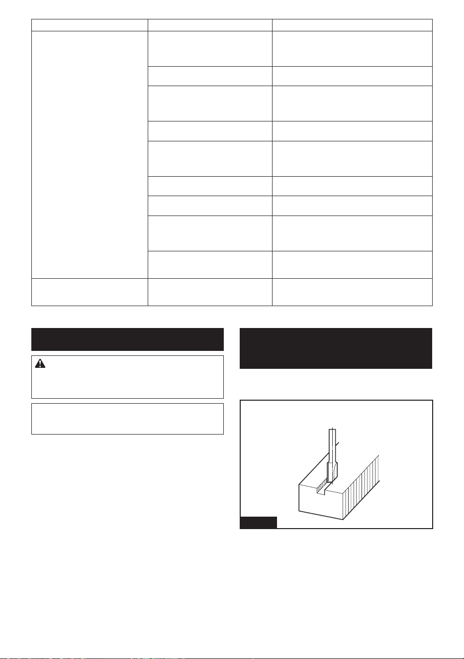
47 ESPAÑOL
Estado de la anomalía Causa probable (avería) Remedio
La aspiradora no funciona junto con
el interruptor de la herramienta.
La unidad inalámbrica no está instalada
en la herramienta.
La unidad inalámbrica está instalada
incorrectamente en la herramienta.
Instale la unidad inalámbrica correctamente.
La terminal de la unidad inalámbrica y/o
la ranura está sucia.
Retire con cuidado el polvo y la suciedad en la
terminal de la unidad inalámbrica y limpie la ranura.
El botón de activación inalámbrica en la
herramienta no se ha oprimido.
Oprima el botón de activación inalámbrica durante
un lapso breve y asegúrese de que la luz indicadora
de activación inalámbrica esté parpadeando en
azul.
El interruptor de modo en espera en la
aspiradora no está ajustado en “AUTO”.
Ajuste el interruptor de modo en espera en la
aspiradora en “AUTO”.
Más de 10 herramientas están registra-
das en la aspiradora.
Vuelva a realizar el registro de la herramienta.
Si más de 10 herramientas están registradas en la
aspiradora, la herramienta registrada al principio se
cancelará automáticamente.
La aspiradora borró todos los registros
de la herramienta.
Vuelva a realizar el registro de la herramienta.
No hay suministro de energía. Suministre energía a la herramienta y a la
aspiradora.
La herramienta y la aspiradora están
lejos una de la otra (fuera del rango de
transmisión).
Acerque más la herramienta a la aspiradora. La
distancia máxima de transmisión es de aproxima-
damente 10 m, pero puede variar en función de las
circunstancias.
La perturbación radioeléctrica generada
por otros aparatos que emiten ondas de
radio de alta intensidad.
Mantenga la herramienta y la aspiradora lejos de
aparatos tales como dispositivos Wi-Fi y hornos de
microondas.
La aspiradora funciona mien-
tras la herramienta no está en
funcionamiento.
Otros usuarios están usando la activa-
ción inalámbrica de la aspiradora con
sus herramientas.
Apague el botón de activación inalámbrica de las
demás herramientas o cancele el registro de dichas
herramientas.
MANTENIMIENTO
PRECAUCIÓN: Asegúrese siempre de que la
herramienta esté apagada y el cartucho de batería
extraído antes de intentar realizar una inspección
o mantenimiento.
AVISO: Nunca use gasolina, bencina, diluyente
(tíner), alcohol o sustancias similares. Puede que
esto ocasione grietas o descoloramiento.
Para mantener la SEGURIDAD y FIABILIDAD del pro-
ducto, las reparaciones, y cualquier otra tarea de man-
tenimiento o ajuste deberán ser realizadas en centros
de servicio autorizados o de fábrica Makita, empleando
siempre repuestos Makita.
FRESAS DE LA
REBAJADORA
Accesorio opcional
Fresa recta
Fig.58

48 ESPAÑOL
Fresa con ranura en “U”
Fig.59
Fresa con ranura en "V"
Fig.60
Fresa de corte a ras con punta de taladro
Fig.61
Fresa de corte doble a ras con punta de taladro
Fig.62
Fresa para juntas de paneles
Fig.63
Fresa de redondeo de esquinas
Fig.64
Fresa de biselado
Fig.65
Fresa de moldura de ensenada
Fig.66
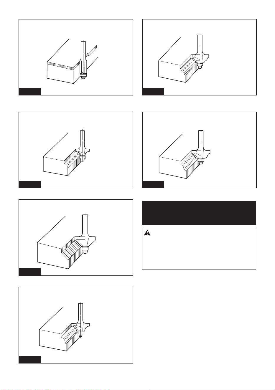
49 ESPAÑOL
Fresa de recorte a ras con rodamiento de balines
Fig.67
Fresa de redondeo de esquinas con rodamiento de
balines
Fig.68
Fresa de biselado con rodamiento de balines
Fig.69
Fresa de moldura con rodamiento de balines
Fig.70
Fresa de ensenada con rodamiento de balines
Fig.71
Fresa de arco conopial romano con rodamiento de
balines
Fig.72
ACCESORIOS
OPCIONALES
PRECAUCIÓN: Estos accesorios o aditamen-
tos están recomendados para utilizarse con su
herramienta Makita especicada en este manual.
El empleo de cualquier otro accesorio o aditamento
puede conllevar el riesgo de lesiones personales.
Utilice los accesorios o aditamentos solamente para
su n establecido.
Si necesita cualquier ayuda para más detalles en
relación con estos accesorios, pregunte a su centro de
servicio local Makita.
• Fresas rectas y de formación de ranuras
• Fresas de formación de bordes
• Fresas de recorte de laminados
• Conjunto de la guía recta
• Montaje de guía recta de ajuste no
• Conjunto de la guía de recorte
• Sujetador de la guía
• Guía de plantilla
• Adaptador de guía de plantilla
• Tuerca de sujeción
• Cono de sujeción
• Manguito de sujeción
• Deector de astillas

50 ESPAÑOL
• Adaptador del carril guía
• Unidad inalámbrica
• Batería y cargador originales de Makita
NOTA: Algunos de los artículos en la lista pueden
incluirse en el paquete de la herramienta como acce-
sorios estándar. Éstos pueden variar de país a país.
GARANTÍA LIMITADA DE
MAKITA
Ésta Garantía no aplica para México
Consulte la hoja de la garantía anexa para ver los
términos más vigentes de la garantía aplicable a este
producto. En caso de no disponer de esta hoja de
garantía anexa, consulte los detalles sobre la garantía
descritos en el sitio web de su país respectivo indicado
a continuación.
Estados Unidos de América: www.makitatools.com
Canadá: www.makita.ca
Otros países: www.makita.com

51

Some dust created by power sanding, sawing, grinding, drilling, and other
construction activities contains chemicals known to the State of California
to cause cancer, birth defects or other reproductive harm. Some examples
of these chemicals are:
• lead from lead-based paints,
• crystalline silica from bricks and cement and other masonry products, and
• arsenic and chromium from chemically-treated lumber.
Your risk from these exposures varies, depending on how often you do this
type of work. To reduce your exposure to these chemicals: work in a well
ventilated area, and work with approved safety equipment, such as those
dust masks that are specially designed to filter out microscopic particles.
WARNING
< USA only >
ADVERTENCIA
Algunos polvos creados por el lijado, aserrado, esmerilado, taladrado y
otras actividades de la construcción contienen sustancias químicas
reconocidas por el Estado de California como causantes de cáncer, defectos
de nacimiento y otros peligros de reproducción. Algunos ejemplos de estos
productos químicos son:
• plomo de pinturas a base de plomo,
• sílice cristalino de ladrillos y cemento y otros productos de albañilería, y
• arsénico y cromo de maderas tratadas químicamente.
El riesgo al que se expone varía, dependiendo de la frecuencia con la que
realice este tipo de trabajo. Para reducir la exposición a estos productos
químicos: trabaje en un área bien ventilada y póngase el equipo de seguridad
indicado, tal como las máscaras contra polvo que están especialmente
diseñadas para filtrar partículas microscópicas.
< Sólo en los Estados Unidos >
Makita Corporation
3-11-8, Sumiyoshi-cho,
Anjo, Aichi 446-8502 Japan
www.makita.com
885A70-941
GPR01-1
EN, ESMX
20240213