IMPORTANT: Read all instructions carefully before using this product.
Retain this owner’s manual for future reference.
The specifications of this product may vary from this photo, subject to
change without notice.
2636.7-060920
ROWER MACHINE


1
SERVICE ------------------------------------------------------------------------
2
LABEL PLACEMENT----------------------------------------------------------
3
IMPORTANT SAFETY GUIDELINES ------------------------------------
4
OVERVIEW DRAWING ------------------------------------------------------
5
PARTS LIST ---------------------------------------------------------------------
6
HARDWARE PACK-------------------------------------------------------------
8
ASSEMBLY ----------------------------------------------------------------------
9
CONSOLE -----------------------------------------------------------------------
15
WORKOUT-----------------------------------------------------------------------
16
ADJUSTMENTS & TRANSPORTING------------------------------------
17
STORAGE ----------------------------------------------------------------------
18
TROUBLESHOOTING & MAINTENANCE------------------------------
29
WARRANTY --------------------------------------------------------------------
20
PARTS REQUEST FORM---------------------------------------------------
21
TABLE OF CONTENT

2
IMPORTANT: FOR NORTH AMERICA ONLY
For damaged or defective product, questions, replacement parts or any other service
support, please contact our customer service department by the below methods:
For The Best Service, please Email:
service@paradigmhw.com
Response Time: 1-2 Business Days
Emailing us with the information above will be the best method to receive a response during
peak business hours
Website:
www.paradigmhw.com
Toll-Free:
1-844-641-7920
(8:00 AM - 5:00 PM Pacific Standard Time, Monday thru Friday)
Response time may vary via calling
Please have the following information ready when requesting for service:
Your name
Phone number
Model number
Serial number
Part number
Proof of Purchase
For damaged or defective product, please contact our customer service before returning to
the store.
Paradigm Health & Wellness, Inc.
1189 Jellick Ave.
City of Industry, CA 91748, USA
SERVICE
3
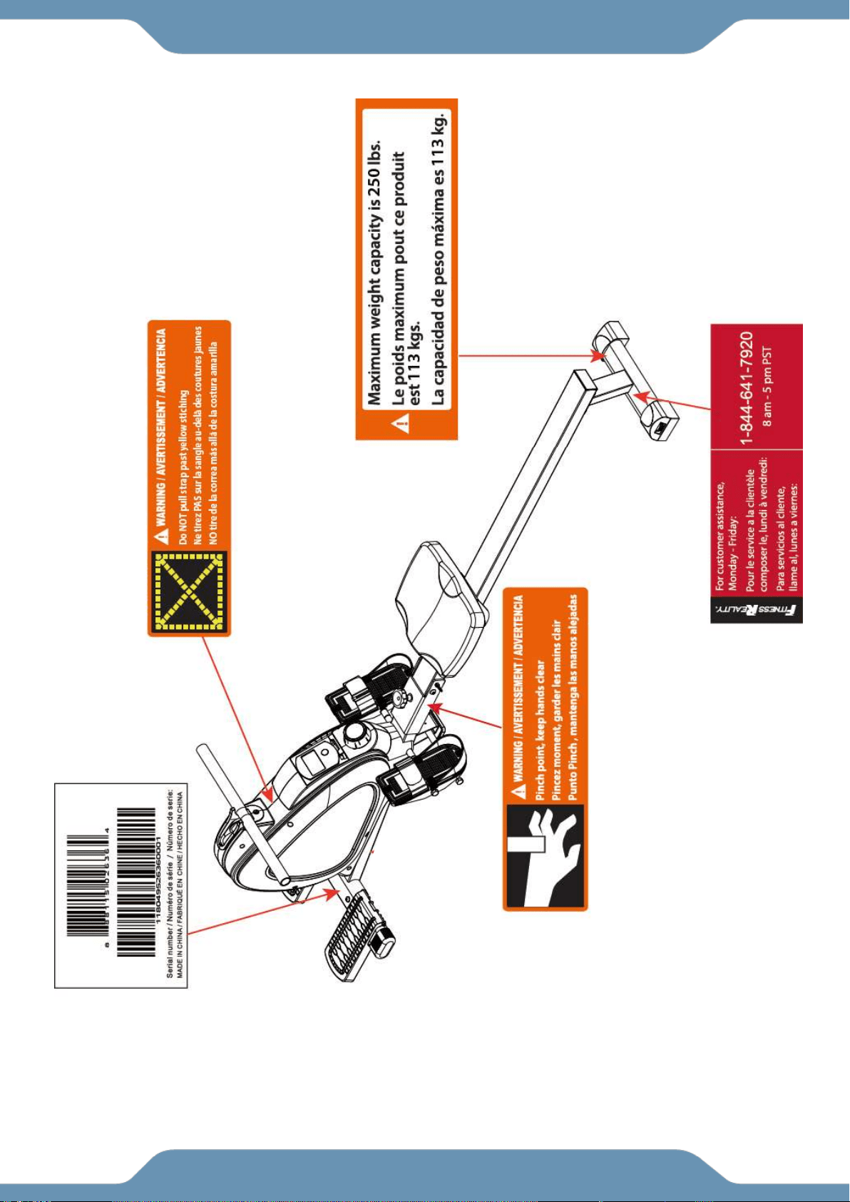
LABEL PLACEMENT

4
Read all instructions before using the Rower. Basic precautions should always be followed.
WARNING - To reduce the risk of injury to persons, read the following:
1. Be sure all screws, nuts, and bolts are tightened prior to use.
2. Before using this equipment, we recommend doing warm ups.
3. Only one person should be using the equipment at a time.
4. Never operate this Rower if it is not working properly, has been dropped, or damaged. If a problem
is encountered, contact Customer Service before using the Rower again.
5. Always use this equipment on a clear and level surface.
6. It is recommended that you place this exercise equipment on an equipment mat.
7. For household use only.
8. Do not use outdoors or near water.
9. Use this product only for its intended use as described in this manual. Do not use attachments
NOT recommended by the manufacturer.
10. Do not wear loose clothing when using the equipment.
11. Never drop or insert any object into any opening.
12. If at any time you feel faint, light-headed, or dizziness while operating the equipment, stop
exercising immediately. You should also stop exercising if you are experiencing pain or any
discomfort.
13. Keep children and pets away from equipment when in use.
14. For any problems, contact Customer Service. Servicing should be performed by an authorized
service representative. Our contact number is on the service page.
15. This product requires a minimum of 6 square feet of space for safe operation.
16. ASSEMBLE ALL HARDWARE IN THE ORDER THAT IS SHOWN IN THE ILLUSTRATIONS.
Serious bodily injury can occur if this equipment is not assembled and used correctly.
17. Warning: - Risk of Personal Injury - Keep children under the age of 13 away from the
equipment.
18. Warning: - Risk of Personal Injury - Keep body parts, hair, loose clothing, and jewelry
clear of all moving parts.
19. Warning: Before using this equipment, you should consult with your personal
physician to see if the product is appropriate for you. Do not use this equipment
without your physician’s approval if you have any of the following conditions or
ailments:
Extreme obesity
Glaucoma, retinal detachment or conjunctivitis
Pregnancy
Spinal injury, Cerebral Sclerosis, or acutely swollen joints
Middle ear infection
High blood pressure, Hypertension, Recent stroke or Transient ischemic attack
Heart or circulatory disorders for which you are being treated
Hiatus hernia or Ventral hernia
Bone weaknesses including Osteoporosis, Unhealed fractures, Modularly pins, or
Surgically implanted orthopedic supports
Use of anti-coagulants including Aspirin in high doses
The maximum weight capacity for this product is 250 lbs / 113 kg.
DO NOT EXCEED MAXIMUM WEIGHT CAPCITY.
IMPORTANT SAFETY GUIDELINES
5
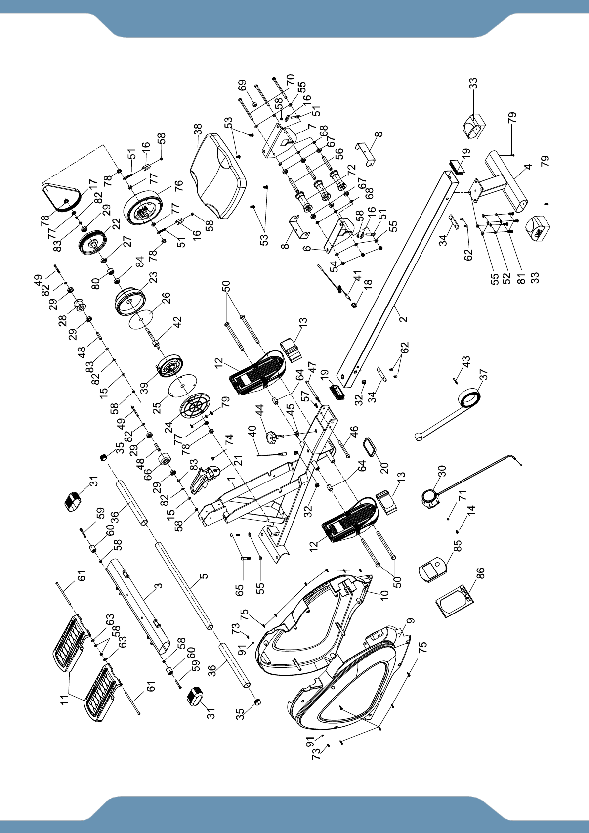
OVERVIEW DRAWING

6
No.
Description
Qty
No.
Description
Qty
1
Main Frame
1
31
Front Stabilizer End Cap
2
2
Slide Tube
1
32
Wire Plug
3
3
Front Stabilizer
1
33
Rear Stabilizer End Cap
2
4
Rear Stabilizer
1
34
Rubber Pad
2
5
Handlebar
1
35
Handlebar End Cap
2
6
Left Seat Plate
1
36
Foam Grip
2
7
Right Seat Plate
1
37
Braid
1
8
Seat Bracket
2
38
Seat
1
9
Left Cover
1
39
Coil Spring
1
10
Right Cover
1
40
Middle Sensor Wire
1
11
Pedal Pad
2
41
Sensor
1
12
Pedal
2
42
Axle
1
13
Pedal Strap
2
43
Phillips ScrewM5×35
1
14
Phillips ScrewM5*20
1
44
Round Knob
1
15
Flat Washer OD12×ID6.5×1.5
2
45
Flat Washer OD25*ID12.5*2.0
1
16
U-Bracket
4
46
Hex Bolt Ø10×95×M6
1
17
Belt6PJ250
1
47
Safety Pin Ф11*7*Ф8*106
1
18
Wire Plug
1
48
Bushing Ф10*Ф6.1*40
2
19
End Cap
2
49
Hex Bolt M6*55
2
20
Foot Pad
1
50
Hex Bolt M12*Ф12.5*160
4
21
Handlebar Bracket
1
51
Eye Bolt M6*40
4
22
Belt Pulley
1
52
Spring Washer ID8.5×1.5
4
23
Drawstring Pulley
1
53
Bolt M8*16
4
24
Spring Bumper Cover
1
54
Nylon Nut M8
3
25
acoustic baffle-A
1
55
Flat Washer OD16×ID8.5×1.5
12
26
acoustic baffle-B
1
56
Bushing
3
27
Bearing 6003
1
57
Round Head Hex Bolt M6*15
1
28
Braid Pulley
1
58
Nylon Nut M6
10
29
Bearing 6000ZZ
5
59
Round Head Hex BoltM6*45
2
30
Tension Controller
1
60
Transporting Wheel §22*6.5*30
2
PARTS LIST

7
No.
Description
Qty
No.
Description
Qty
61
Pedal Post M6*140
2
76
Flywheel Ø176
1
62
Socket Phillips Screw M6*10
4
77
Hex Nut M10×1.0
4
63
Flat Washer OD13×ID6.5×1.5
2
78
Flange NutM10×1.0
4
64
Bushing Ф18*Ф13*26
2
79
Self-Tapping Phillips
ScrewST4.0*19
5
65
Round Head Hex Bolt M8*45,
2
80
One direction BearingHR1712
1
66
Wheel Ф50*35
1
81
Round Head Hex BoltM8×20,
4
67
Bearing 608ZZ
6
82
C-Ring Ø10
5
68
BushingOD15*ID8.0*4.1
6
83
Wave WasherOD13.5*ID10.2*0.4
3
69
MagnetФ15*7
1
84
Bearing 16003
1
70
Hex Bolt M8*125,
3
85
Console
1
71
Flat WasherOD12×ID5.5×1.5
1
86
Console Bracket
1
72
Rolling Wheel
3
87
5mm Allen Wrench
1
73
Self-Tapping Phillips Screw
ST4.0*12
2
88
6mm Allen Wrench
1
74
Phillips ScrewM5*12
1
90
Open Wrench
1
75
Self-Tapping Phillip
ScrewST4.0*16
11
91
Flat Washer Ø10
2
PARTS LIST
8
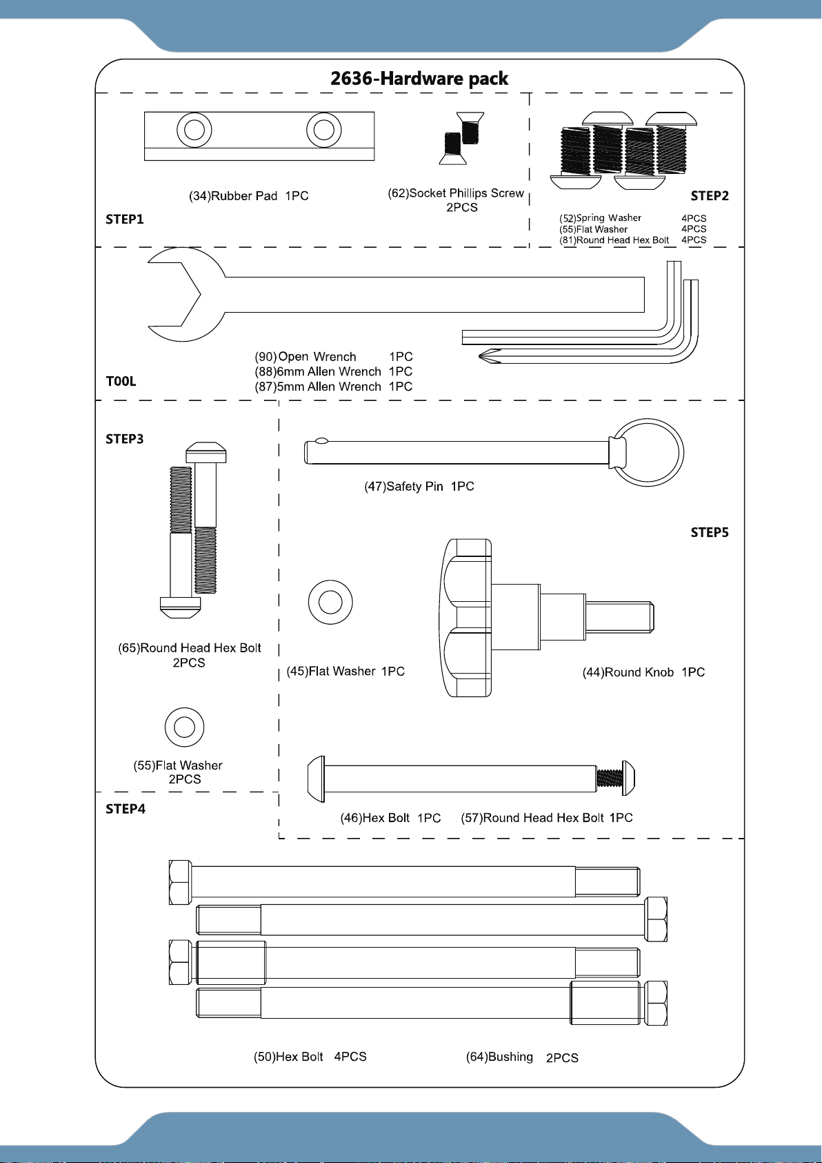
HARDWARE & TOOLS PACK
9
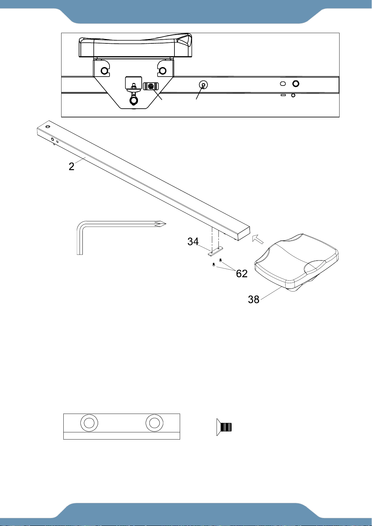
Step 1
1A. Installing the Seat
Slide the Seat (38) onto the Sliding Tube (2). Make sure Magnet (69) and Sensor (41) are on the
same side when installing the Seat (38). SEE Fig. A.
Attach the Rubber Pad (34) onto the underside of the Sliding Tube (2) with two Socket Phillips
Screws (62). Tighten using the 5mm Allen Wrench with Phillips Screwdriver provided.
NOTE: The narrow edge of the Rubber Pad (34) should be pointing towards the Seat (38).
ASSEMBLY
Hardware:
(34) Rubber Pad
1 PC
(62) Socket Phillips
Screw
2 PCS
5mm Allen Wrench with
Phillips Screwdriver 1PC
Tool:
4169
Fig. A
IMPORTANT!!!
10
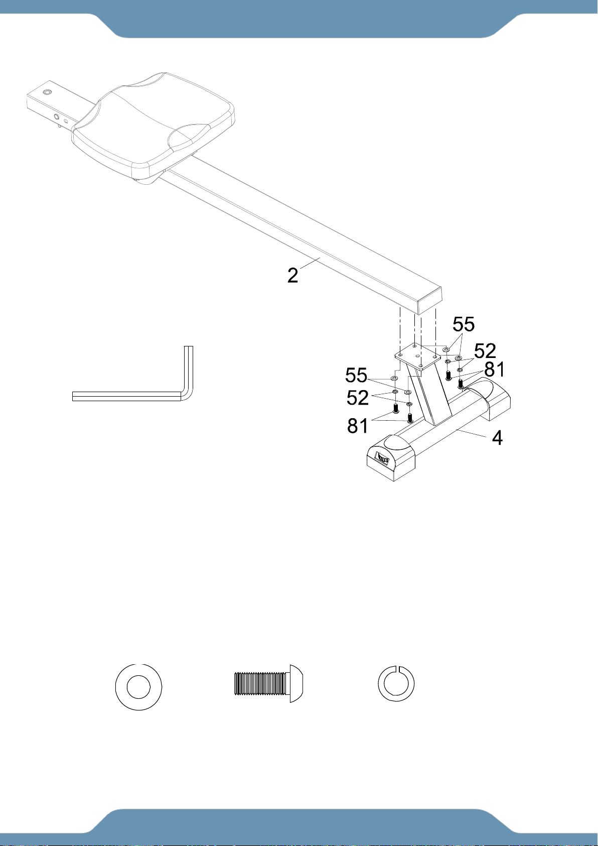
Step 2
2A. Installing the Rear Stabilizer
Attach the Rear Stabilizer (4) onto the underside of the Sliding Tube (2) with four Flat Washers
(55), four Spring Washers (52), and four Round Head Hex Bolts (81). Tighten using the 6mm
Allen Wrench provided.
ASSEMBLY
6mm Allen Wrench 1PC
Tool:
Hardware :
(55) Flat Washer
4 PCS
(81) Round Head
Hex Bolt
4 PCS
(52) Spring Washer
4 PCS
11
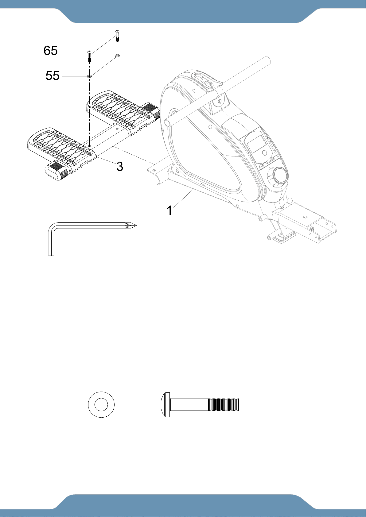
Step 3
3A. Installing the Front Stabilizer
Attach the Front Stabilizer (3) onto the Main Frame (1) with two Flat Washers (55), and two
Round Head Hex Bolts (65). Tight using the 5 mm Allen Wrench with Phillips Screwdriver
provided.
ASSEMBLY
5mm Allen Wrench with
Phillips Screwdriver
1PC
Tool:
(55) Flat Washer
2 PCS
(65) Round Head
Hex Bolt
2 PCS
Hardware :
12
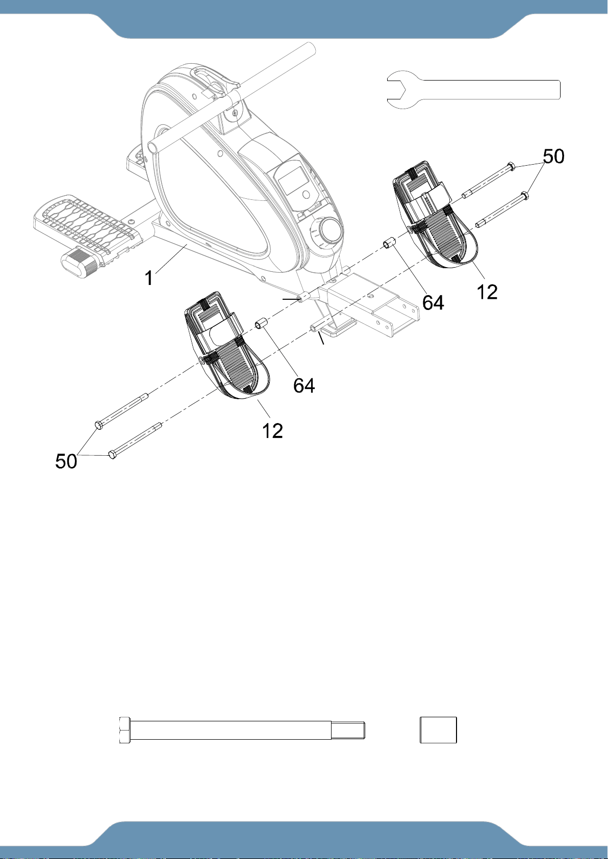
Step 4
4A. Installing the Pedals
Attach one Hex Bolt (50) into the LOW bolt hole on the left side of the Main Frame (1). Tighten
using the Open Wrench provided.
Slide one Hex Bolt (50) through the center of the Pedal (12), then slide a Bushing (64) onto the
end of that Hex Bolt (50). Attach the group of parts to the TOP bolt hole on the left side of the Main
Frame (1). Tighten using the Open Wrench provided.
Repeat for the left side.
NOTE: The heel of the Pedals (12) will rest on the lower Hex Bolt (50).
ASSEMBLY
Hardware:
(50) Hex Bolt
4 PCS
(64) Pedal Bushing
2 PCS
LOW
TOP
Tool:
Open Wrench 1PC
13
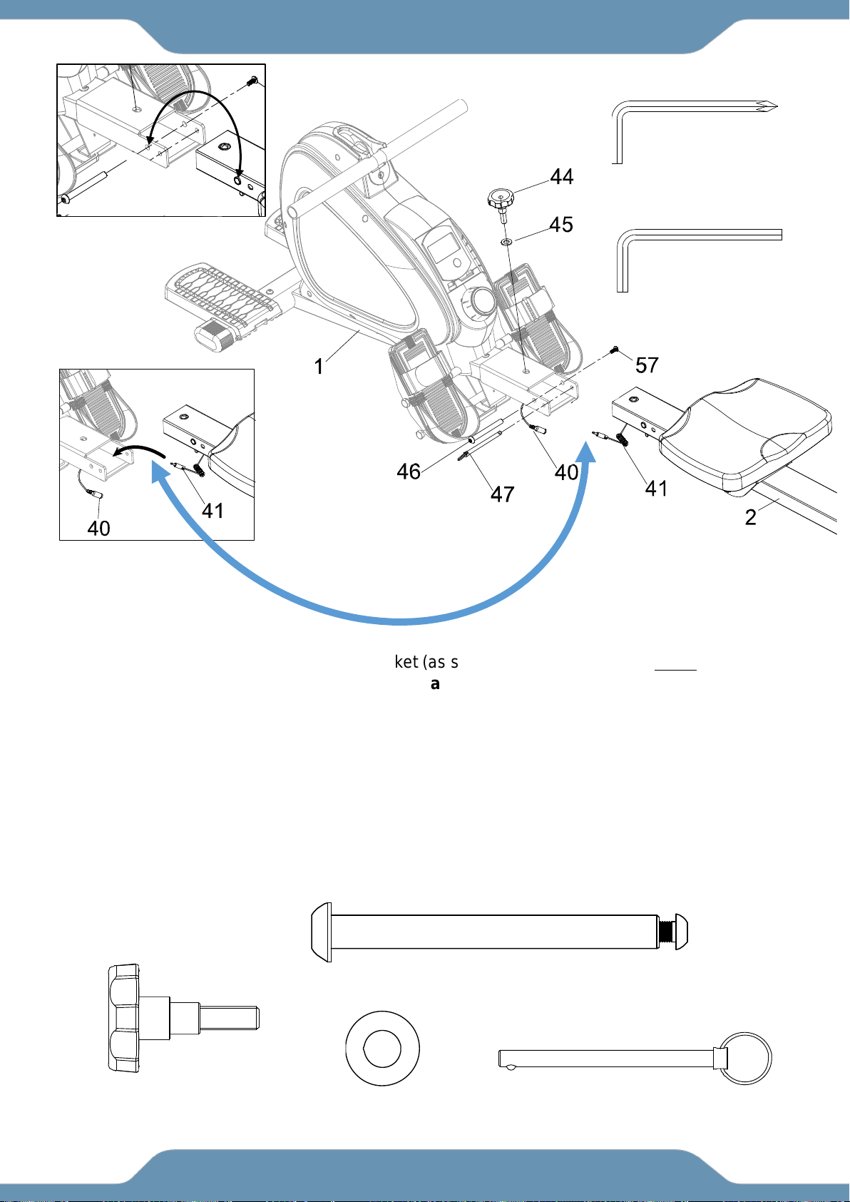
Step 5
5A. Installing the Seat Sliding Tube
Guide the Sensor Wire (41) through the bracket (as shown in Fig. B) while you angle the Sliding
Tube (2) to insert it into the bracket of the Main Frame (1). Connect the Middle Sensor Wire (40)
with the Sensor Wire (41).
Align the bolt holes shown in FIG. A, and insert one Hex Bolt (46). Push the Hex Bolt (46) through
the frame and attach one Round Head Hex Bolt (57). Tighten using the 5mm Allen Wrench with
Phillips Screwdriver and 6mm Allen Wrench provided.
Insert the Safety Pin (47) to align and secure the Main Frame (1) and the Sliding Tube (2).
Further secure the Main Frame (1) and Sliding Tube (2) with one Flat Washer (45) and one
Round Knob (44).
ASSEMBLY
5mm Allen Wrench with
Phillips Screwdriver 1PC
6mm Allen Wrench
1PC
Tool:
(46) Hex Bolt
1PC
(57) Round Head
Hex Bolt
1PC
(45) Flat Washer
1PC
(44) Round Knob
1PC
(47) Safety Pin
1PC
FIG. A
Hardware:
FIG. B
IMPORTANT
14
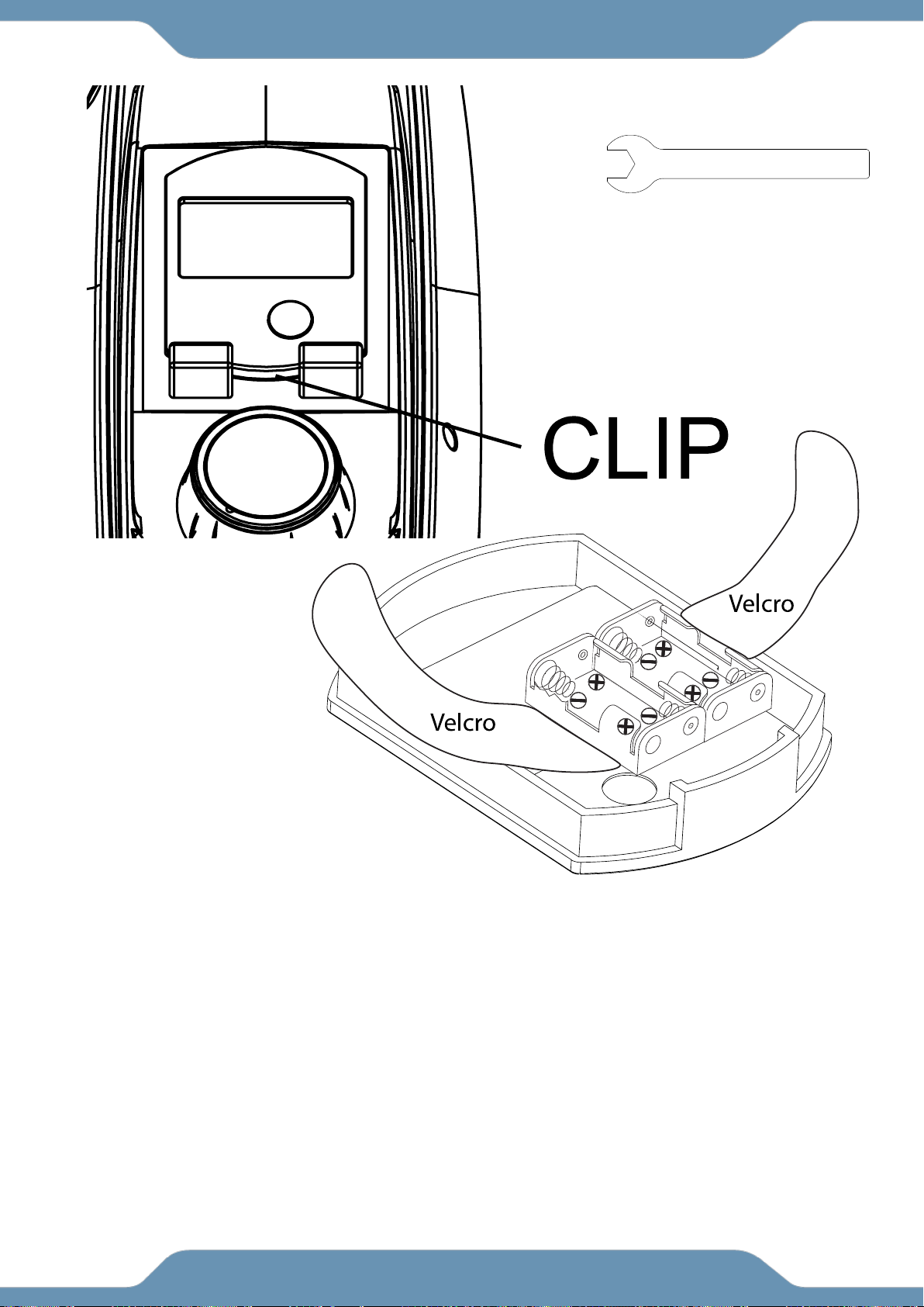
Step 6
6A. Installing the Console Batteries
To help remove the console you may want to use the wrench to pry the console clip up using the
Open Wrench to unclip it.
BECAREFUL when pulling the console out, There are wires connecting the console to the internal
speed sensor.
Open the Velcro straps and install the batteries. The positive and negative poles are labeled in the
image above.
After installing the batteries, secure the batteries in place with the Velcro strap. Make sure the
consoles wires are securely clipped together, and then reinsert the console.
Lorem ipsum
Lorem ipsum
ASSEMBLY
Tool:
Open Wrench 1PC
15
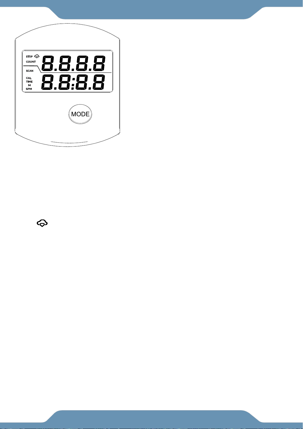
USING THE CONSOLE
Power On: The console will turn on when the user starts
rowing or presses the mode button.
Power Off: The console will automatically turn off after 20
minutes of inactivity.
Reset: Press and hold the MODE button for 3 seconds to
reset the console.
MODE button: Press this button during a workout to switch
between SCAN, CAL, TIME, M, and SPM.
WORKOUT VALUES
COUNT: Will track the total number of strokes/pulls during the workout, up to a total of 9999.
CAL: Will track the number of calories burned during the workout, up to a value of 9999. This
is only an estimate value base on an average user.
TIME: Will track the workout length, up to a maximum value of 99:59 minutes.
SCAN: This will make the display automatically rotate between the workout value being
displayed. The work value being displayed will shift every 4 seconds.
M: This will track your distance in meters, up to a maximum value of 9999 meters.
SPM: This will track the average number of strokes per minute.
: The MyCloudFitness symbol turns on the Bluetooth antenna is connected.
o If you have problem connecting to the app, make sure your Bluetooth antenna is
turned on, restart the app, reset the console, and try connecting again.
CONSOLE
16
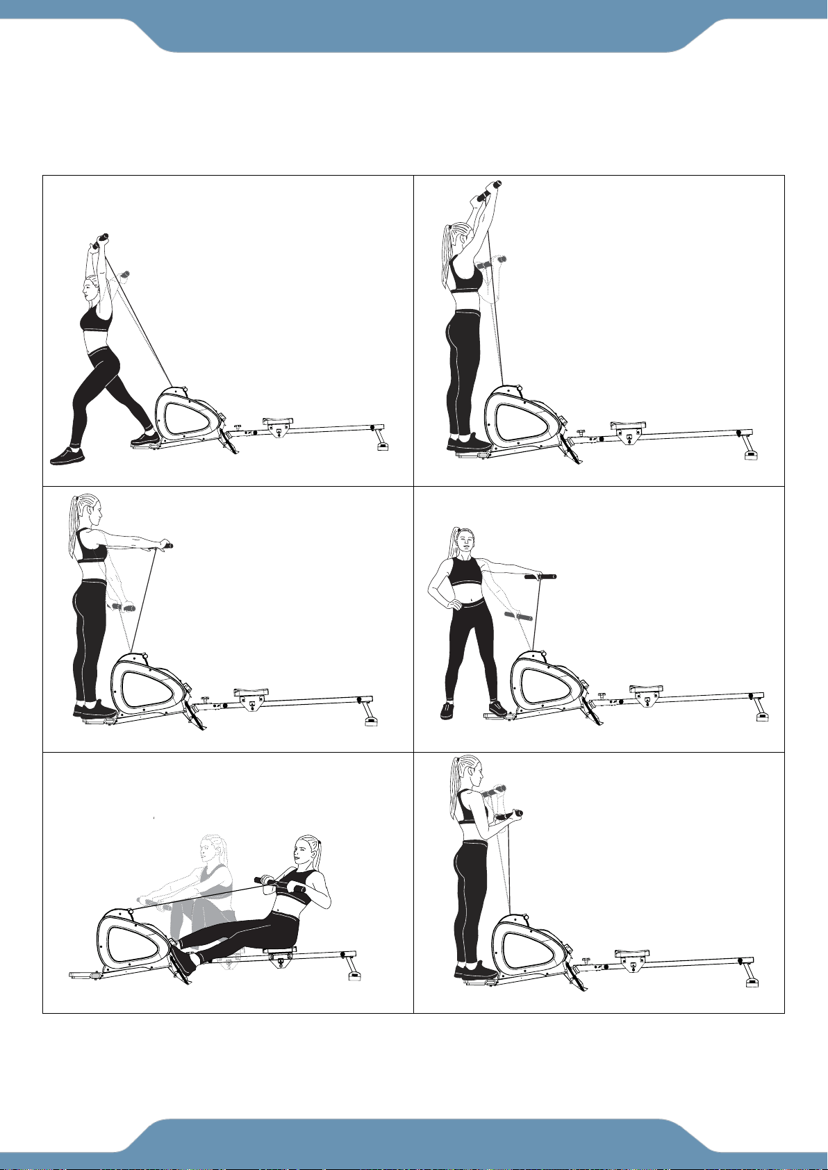
The Images below show the workouts that one can do while on the rowing machines.
Always have your feet secure placed on the foot platform at the front of the machine or
strapped to the foot pedals when working out.
The dashed lines show the starting position of the workout, and the solid lines show the end
position of the workout.
Front Raises:
Works out the front
of the shoulders
Side Raises: Works
out the side of the
shoulders
Shoulder Press:
Works out the
shoulders
Tricep Extensions:
Works out the
triceps.
Rowing: Full body workout
Always use the Velcro straps when rowing.
Curls: Works out
the Biceps.
WORKOUT
17
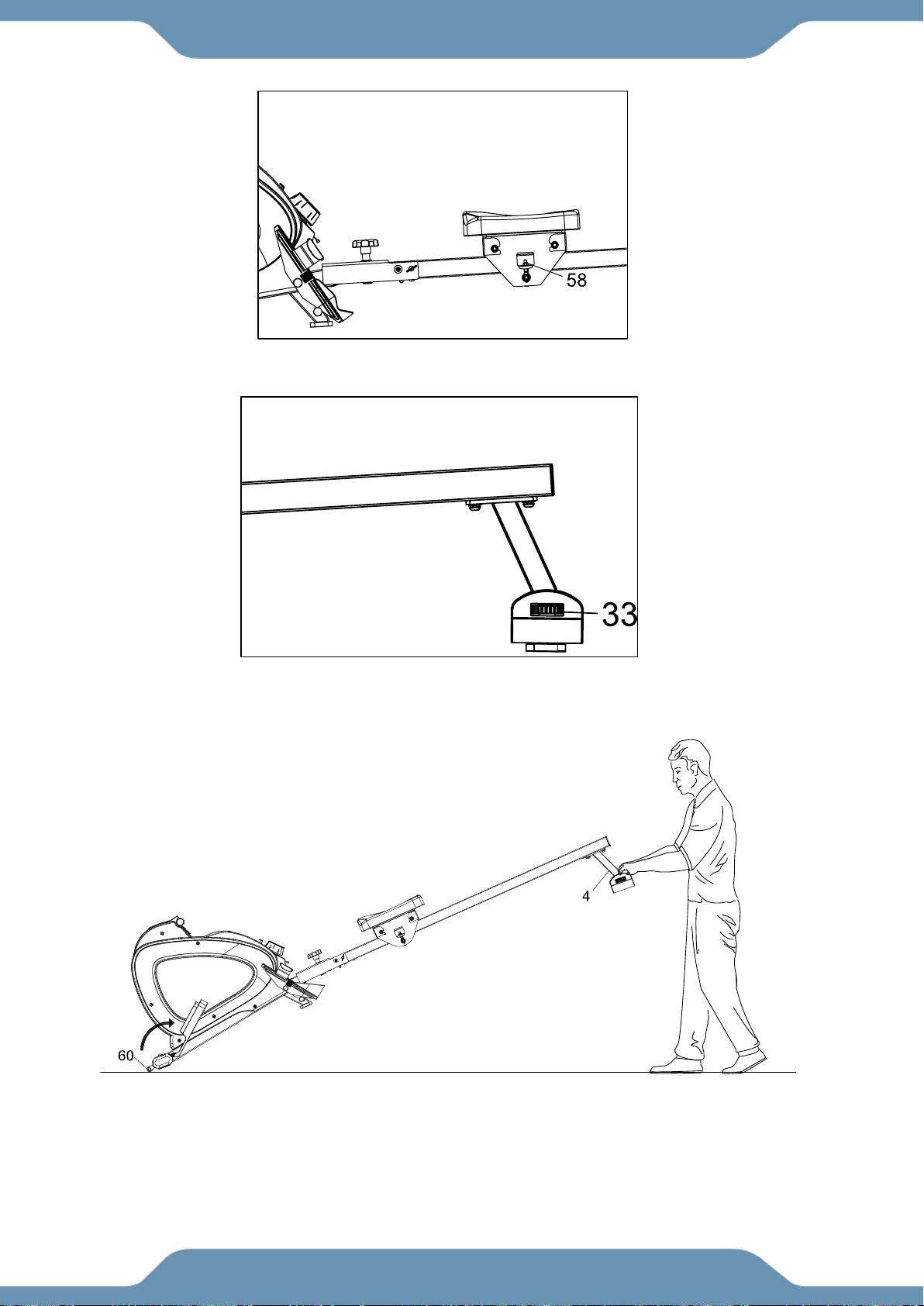
If the seat does not slide easily, or the seat shakes too much, adjust the Nylon Nut (58).
If the frame is shaking while in use, extend the foot on the Rear Stabilizer End Caps (33) to
balance the frame. The extending foot will also improve the grip between the endcaps and
the floor.
Hold the Rear Stabilizer (4) and pull the machine until the wheels on the Front
Stabilizer (3) make contact with the floor. Push or pull the unit to the desired
location, then gently lower the Rear Stabilizer (4) to the ground.
ADJUSTMENTS & TRANSPORTING
Lorem ipsum
Lorem ipsum
Lorem ipsum
Lorem ipsum
18
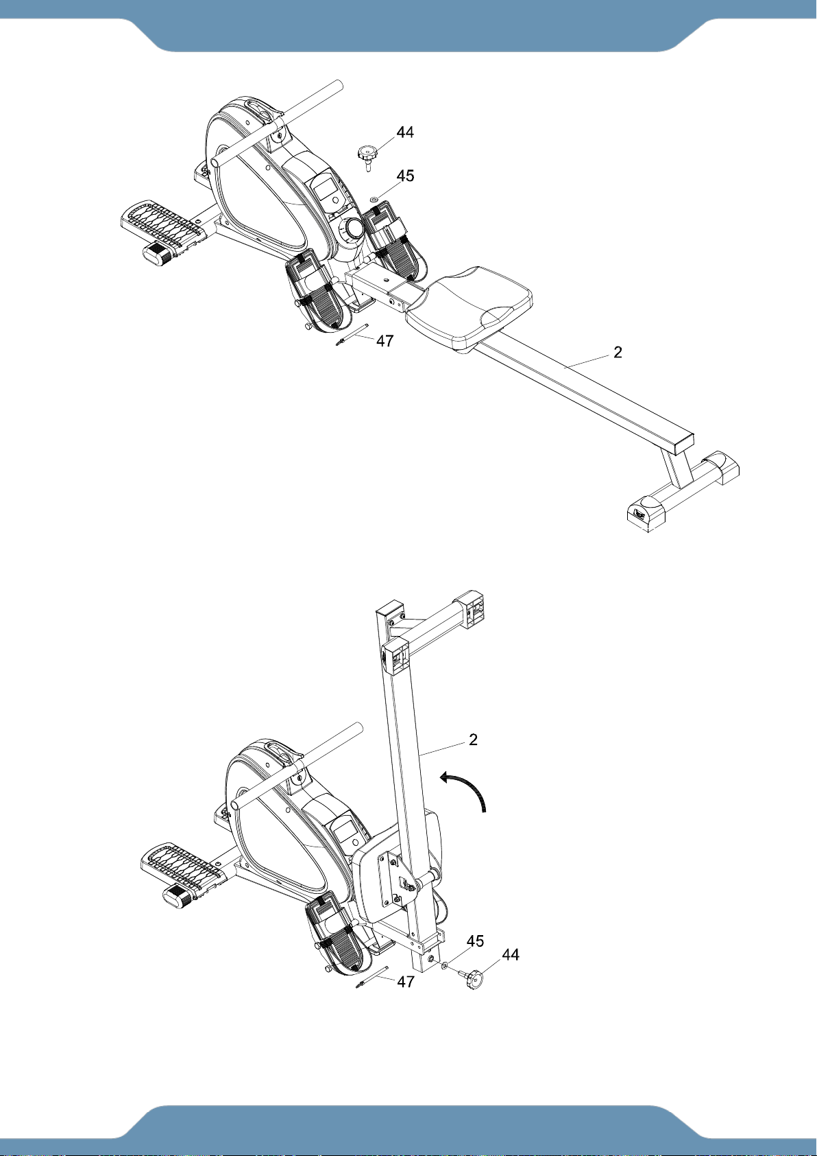
STORAGE
Lift up the Sliding Tube (2) and insert the Safety Pin (47) to lock the Sliding Tube (2) in
the upright position. Insert the Round Knob (44) and Flat Washer (45) back into the
underside of the Sliding Tube (2).
ALWAYS Store the bike in a clean and dry environment away from pets and children.
Remove the Safety Pin (47), the Round Knob (44) and Flat Washer (45) from the
Sliding Tube (2) and the Main Frame (1).

19
CLEANING
The rower can be cleaned with a soft clean damp cloth. Do not use abrasives or
solvents on the plastic parts.
Please wipe your perspiration off the rower after each use. Be careful not to get
excessive moisture on the computer display panel as this might cause an
electrical hazard or the electronics to fail.
Please keep the computer console and the rower, out of direct sunlight to prevent
screen damage.
Please inspect all assembly bolts, nuts, screws, and pedals on the machine for
proper tightness every week.
TROUBLESHOOTING
PROBLEM: There is no display on the computer console.
o SOLUTION: The batteries in the computer console may be dead. Replace
the dead batteries with new batteries. Do NOT mix old and new batteries.
o SOLUTION: Check that the batteries are correctly inserted and the battery
springs are in proper contact with the batteries.
o SOLUTION: Remove the console and verify that the wire at the rear of the
console is properly connected to the wires that come from the frame.
PROBLEM: The rower makes a noise when in use.
o SOLUTION: The bolts may be loose on the equipment. Please inspect all of
the nuts, bolts, screws and tighten any loose Hardware.
o SOLUTION: The change the resistance levels to the lowest setting and see
if the noise continues. Contact Customer service for future assistance.
PROBLEM: The console is on but it is not tracking my workout. The strokes are not
counting up.
o SOLUTION: Make sure the one console wire on the back of the console is
connected.
o SOLUTION: Review STEP 1 and make sure the Magnet 69 and Sensor 41
are on the same side of the seat rail.
o SOLUTION: Check the cables 41 and 40 in STEP 5 are connected and are
NOT damaged or are getting smashed between the main frame and the seat
rail.
PROBLEM: The entire rower moves forward and back while rowing.
o SOLUTION: Use the rower on a surface that will grip the floor stabilizers
better or purchase a workout mat to keep your rower in place.
PROBLEM: The Console does not connect to the APP.
o SOLUTION: Reset the console, restart the APP and try again. The console is reset by
holding the STOP button down for 3-4 seconds.
o SOLUTION: Turn on the Bluetooth antenna on your smart device, restart the app, and try
connecting again.
MAINTENANCE & TROUBLE SHOOTING

20
MANUFACTURER’S LIMITED WARRANTY
Paradigm Health & Wellness warrants to the original purchaser that this product is free from
defects in material and workmanship when used for the purpose intended, under the
conditions that it has been installed and operated in accordance with Paradigm’s Owner’s
Manual. Paradigm’s obligation under this warranty applies to the following:
COMPONENT LENGTH OF WARRANTY
Structural Frame 1 year For Home Use Only
All Other Components 90 days For Home Use Only
Exclusions from Warranty Coverage:
Paradigm does not warrant against and is not responsible for, and no implied warranty shall be deemed to cover, any
product failure, product malfunction, or damages attributable to:
1. Improper installation and/or failure to abide by Paradigm’s installation guidelines;
2. Use of this product beyond normal home use, or in an application for which it was not designed;
3. Cosmetic items such as scratches, dents or discolorations;
4. Damage caused by normal wear and tear, vandalism, accidental or by animals;
5. Any act of Nature (such as fire, flooding, snow, ice, hurricane, earthquake, lightning or other natural disaster),
environmental condition (such as air pollution, mold, mildew, etc.), or staining from foreign substances (such as dirt,
grease, oil, etc.);
6. Normal weathering due to exposure to sunlight, weather and atmosphere which can cause colored surfaces to,
among other things, flake, chalk, accumulate dirt or stains.
7. Improper operation, alteration, handling, storage, abuse or neglect of the products.
Paradigm, using its sole discretion, will either repair or replace free of charge any part(s)
proven to be defective under normal home use. Any repair or replacement shall provide no
new warranty coverage, but shall retain only the remaining portion of the original product’s
warranty. This warranty is offered only to the original purchaser and is not transferable.
Proof of original purchase is required.
Ordering Replacement Parts
Replacement parts can be ordered by emailing our customer service department:
Service@paradigmhw.com
Open Monday thru Friday 8:00 AM - 5:00 PM (PST).
When ordering replacement parts please have the following information ready:
1. Owner’s Manual
2. Model Number
3. Description of Parts
4. Part Number
5. Date of Purchase
WARRANTY

21
Paradigm Health & Wellness, Inc.
EMAIL THIS FORM WITH YOUR RECEIPT OF PURCHASE TO
Service@paradigmhw.com
NAME:______________________________________________________________________
ADDRESS:__________________________________________________________________
CITY:________________________ STATE:_____________ ZIP:________________________
TELEPHONE: (Day)_________________________________________________________
(Night)________________________________________________________
SERIAL#:____________________________________________________________________
MODEL#:____________________________________________________________________
PURCHASE DATE:____________________________________________________________
PLACE OF PURCHASE:________________________________________________________
“YOUR ORDER WILL BE PROCESSED WITHIN 3 BUSINESS DAYS”
*This form can also be faxed to #: 626-810-2166
PART #
DESCRIPTION
QTY
PARTS REQUEST FORM