Loading ...
Loading ...
Loading ...
Installation Instructions (cont'd)
Venting (cont'd)
CUTTING OPENING THROUGH AN OUTSIDE
WALL AND COLLAR INSTALLATION
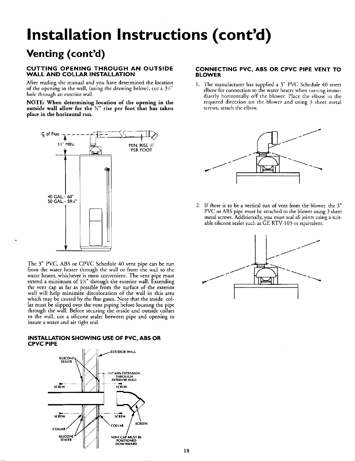
After reading the manual and you have determined the location
of the opening in the wall, (using the drawing below), cut a 3_"
hole through an exterior wall.
NOTE: When determining location of the opening in the
outside wall allow for the V_"rise per foot that has taken
place in the horizontal run.
CONNECTING PVC, ABS OR CPVC PIPE VENT TO
BLOWER
h • ,,
1. T e manufacturer has supplied a 3 PVC Schedule 40 street
elbow for connection to me water heater when turning imme-
diately horizontally off the blower. Place the dbow in the
required direction on the blower and using 3 sheet metal
screws, attach the elbow.
40 GAL.- 60"
50 GAL.- 59½"
The 3" PVC, ABS or CPVC Schedule 40 vent pipe can be run
from the water heater through the wall or from the wall to the
water heater, whichever is most convenient. The vent pipe must
extend a minimum of 1½" through the exterior wall. Extending
the vent cap as far as possible from the surface of the exterior
wall will help minimize discoloration of the wall in this area
which may be caused by the flue gases. Note that the inside col-
lar must be slipped over the vent piping before locating the pipe
through the wall. Before securing the inside and outside collars
to the wall, use a silicone sealer between pipe and opening to
insure a water and air tight seal.
l I
2. If there is to be a vertical run of vent from the blower, the 3"
PVC or ABS pipe must be attached to the blower using 3 sheet
metal screws. Additionally, you must sealall joints using a suit-
able silicone sealer such as GE RTV-103 or equivalent.
/
/
I
INSTALLATION SHOWING USE OF PVC, ABS OR
CPVC PIPE
SILICONE_
SEALER
SCREW /
/
sc_E_w
/
COLLA
SILICONE _
SEAI.ER
/EXTERIOR WALL
-- 1%# MIN.EXTENSION
THROUGH
EXTERIOR WALL
SCREW
VENT CAP MUST BE
POSITIONED
DOWNWARD
18
Loading ...
Loading ...
Loading ...