Loading ...
Loading ...
Loading ...
14
|
CARE & USE/INSTALLATION
MOUNTING BRACKET ASSEMBLY
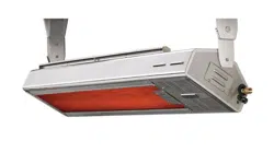
Locate and assemble the mounting brackets based on
your pre-determined mounting distance to the ceiling
(14” if mounting flat, 18” if mounting at an angle). Slide
the long bracket extension INSIDE the main mounting
bracket until the intended set of holes align. The entrance
slot is at the bottom of the main mounting bracket. For
each bracket, use quantity (2) ¼-20 x ½” Hex Bolts (pro-
vided).
Carefully insert each screw through the 2 larger holes of
the main mounting bracket and through the lower holes
(for the 14” position), OR through the 2 upper holes (for
the 18” position) of the mounting bracket extension.
Tighten both nuts securely. Snap the decorative cap over
each larger hole of the main mounting bracket. Repeat
for other bracket. See illustration.
After assembling the mounting brackets, they can be
installed in the pre-selected location. The spacing of the
outer-most sets of holes of the mounting brackets is 48”.
The spacing of the inner-most sets of holes is 45-1/2”. See
mounting bracket spacing diagram on page 12. These
numbers are given to you as a reference for planning.
Mount one single mounting bracket first. Choose the side
which may be the closest to a combustible material. This
way it is easier to measure and determine that the exact
minimum clearance is being adhered to. If mounting onto
wood predrill pilot holes using ¼” drill. (If surface is other
than wood, then anchors will be needed - follow instructions
that come with the anchors) If the mounting bracket is
resting entirely on the wood surface mount using all (4) screws
per bracket. It mounting on the edge of a wood joist then use
the 2 holes closest to the vertical wall of the bracket. Install the second bracket 48” from outer-most set of holes on the
first bracket. THIS WILL CREATE A RESULTING DIMENSION OF EXACTLY 49-3/32” BETWEEN THE EXTENSION ARMS
OF THE BRACKET. If not, then re-measure and mark again. Pre-drill and mount the second bracket.
INSTALLATION...continued
Place the heater into location on the ground directly under the mounting
brackets. Using 2 people, and 2 ladders carefully lift the heater into position.
Place the heater inside the extension arms of the brackets and secure the
heater at both ends, first with (2) ¼-20 x 1” hex head bolts. Mount screws in
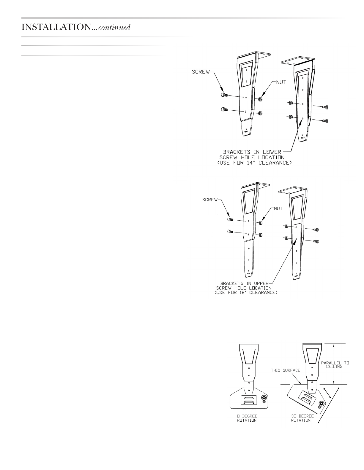
the UPPER holes first. Tilt the heater into the pre-determined angular position
(0-30 degrees). Install the second set of ¼-20 x 1” hex head bolts through
the curved slots directly below the first holes. The maximum 30 degree angle
will be achieved when the screw is ‘bottomed out’ at one end of the curved
slot. This angle can also be sited by looking at the angled surface on the back
of the heater. When the angled surface is PARALLEL to the ground (or the
ceiling) the then heater is at 30 degrees. DO NOT MOUNT THE HEATER
MORE THAN 30 DEGREES, as damage can occur to the protective grill. Al-
ways use the 2 bolts per side and always use the bottom curved slot for angle
positioning (EXCEPTION- eave fascia mounting does not require bottom bolt
for mounting).
Loading ...
Loading ...
Loading ...