Loading ...
Loading ...
Loading ...
20. Mower Removal
a Remove mower belt per instructionsunder"Mower
Drive Belt Removal" through step (c),.
b, Remove retainer spring from clutch rod; pull clutch
rodout of clutch bracket, (Fig 29)
c_ Pull retainer springs out of rear suspension trun-
nions. Remove rear suspension tronnions from lift
brackets (Fig,, 29)1
d,, Pull retainer spring out of rear hinge pin Remove
rear hinge pin, (Fig, 29).
e Pull retainer spring out of front hinge pin,, Remove
front hinge pin (Fig 29).
l, Use lift lever to raise suspension arms, Slide mower
out from under tractor_
NOTE: IFAN ATTACHMENTOTHER THAN THE MOWER
DECK IS TO BE MOUNTED ON THE TRACTOR,
THE LH. AND R,H, SUSPENSION ARMS (FIG,,
29) SHOULD BE REMOVED FROM TRACTOR,
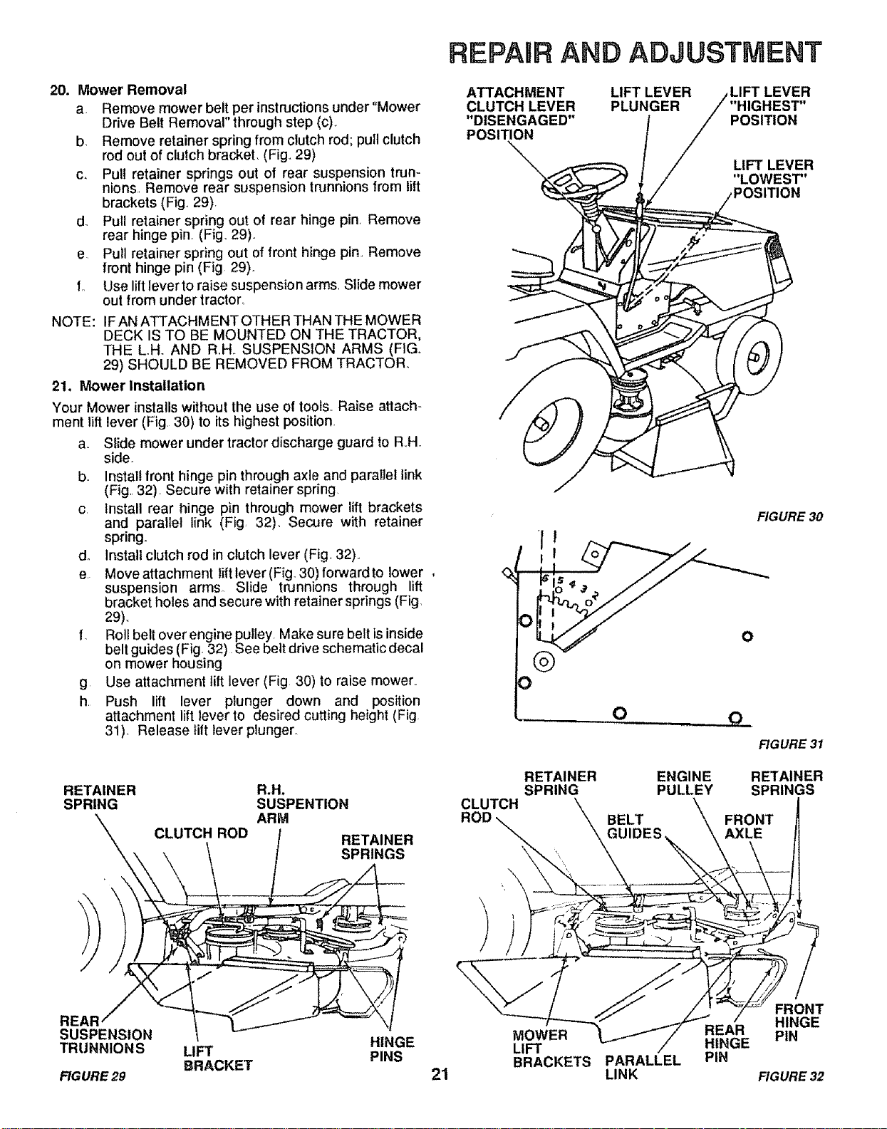
21. Mower Installation
Your Mower installs without the use of tools..Raise atlach-
ment lift lever (Fig, 30) to its highest position
a. Slide mower under tractor discharge guard to RH,
side.
bo Install front hinge pin through axle and parallel link
(Fig,, 32)Secure with retainer spring
c Install rear hinge pin through mower lift brackets
and parallel link (Fig, 32)° Secure with retainer
spring.
do Install clutch rod in clutch lever (Fig, 32).
e, Move attachment lift lever (Figo30) forward to lower
suspension arms, Slide trunnions through lift
bracket holes and secure with retainer springs (Fig,
29),,
f, Roll belt over engine pulley Make sure belt is inside
belt guides (Fig, 32) See belt drive schematic decal
on mower housing
g Use attachment lift lever (Fig 30) to raise mower,,
h Push lift lever plunger down and position
attachment lift lever to desired cutting height (Fig
31), Release lift lever plunger,
RETAINER
SPRING
CLUTCH ROD
a.H°
SUSPENTION
ARM
RETAINER
SPRINGS
REPAIR AND ADJUSTMENT
ATTACHMENT
CLUTCH LEVER
"DISENGAGED"
POSITION
LIFT LEVER
PLUNGER "HIGHEST"
POSITION
LIFT LEVER
"LOWEST"
FIGURE 30
0
CLUTCH
RETAINER
SPRING
O
ENGINE
PULLEY
BELT
GUIDES
O
FIGURE 31
RETAINER
SPRINGS
FRONT
AXLE
REAR
SUSPENSION
TRUNNIONS
FIGURE 29
LIFT
BRACKET
HINGE
PINS
21
MOWER
LIFT
BRACKETS
PARALLEL
LINK
REAR
HINGE
PIN
/
FRONT
HINGE
PIN
FIGURE 32
Loading ...
Loading ...
Loading ...