Loading ...
Loading ...
Loading ...
TO REPLACE MOTION DRIVE BELT
Park the tractor on level surface_ Engage
parking brake. For assistance, there is a
belt installation guide decal on bottom
side of left footresL
• Remove mower (See"TO REMOVE
MOWER" in this section of this manuaL)
• Disconnect clutch wire harness.
• Remove clutch Iocator.
, Remove belt from stationary idler and
clutching idler.
• Pull belt stack toward rear of tractor.
Carefully remove belt upwards from
transmission input pulley and over
cooling fan blades.
• Pull belt toward front of tractor and re-
move downwards from around electric
clutch,
• Install new belt by reversing above pro-
cedure,
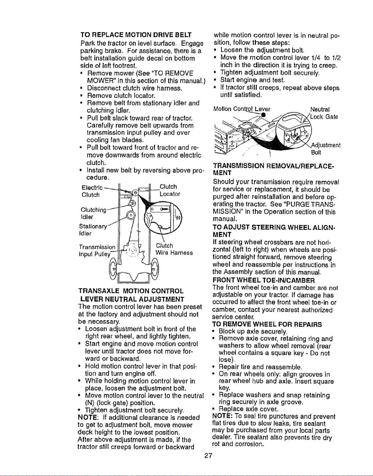
EI_ Clutch
Clutch Locator
Clutchi
Idler
Statlonar_
idler
Transmission Clutch
input Wire Harness
TRANSAXLE MOTION CONTROL
LEVER NEUTRAL ADJUSTMENT
The motion control lever has been preset
at the factory and adjustment should not
be necessary.
• Loosen adjustment bolt in front of the
right rear wheel, and lightly tighten.
, Start engine and move motion control
lever untii tractor does not move for-
ward or backward.
• Hold motion control lever in that posi-
tion and turn engine off.
• While holding motion control lever in
place, loosen the adjustment bolt.
• Move motion control lever to the neutral
(N) (lock gate) position.
- Tighten adjustment bolt securely.
NOTE: If additional clearance is needed
to get to adjustment bolt, move mower
deck height to the lowest position.
After above adjustment is made, if the
tractor still creeps forward or backward
while motion control lever is in neutral po-
sition, follow these steps:
• Loosen the adjustment boll
° Move the motion control lever 1/4 to 1/2
inch in the direction it is trying to creep.
• Tighten adjustment bolt securely.
* Start engine and test.
° If tractor still creeps, repeat above steps
until satisfied°
Motlon Laver Neutral
Gate
! Bolt
TRANSMISSION REMOVAL/REPLACE-
MENT
Should your transmission require removal
for service or replacement, it should be
purged after reinstallation and before op-
erating the tractor. See "PURGE TRANS-
MISSION" In the Operation section of this
manual.
TO ADJUST STEERING WHEEL ALIGN-
MENT
If steering wheel crossbars are not hori-
zontal (left to right) when wheels are posi-
tioned straight forward, remove steering
wheel and reassemble per instructions in
the Assembly section of this manual.
FRONT WHEEL TOE-IN/CAMBER
The front wheel toe-in and camber are not
adjustable on your tractor If damage has
occurred to affect the front wheel toe-in or
camber, contact your nearest authorized
service center.
TO REMOVE WHEEL FOR REPAIRS
° Block up axle securely,
° Remove axle cover, retaining ring and
washers to allow wheel removal (rear
wheel contains a square key - Do not
tose),
• Repair tire and reassemble.
• On rear wheels only: align grooves in
rear wheel hub and axle_ Insert square
key,
° Replace washers and snap retaining
ring securely in axle groove.
• Replace axle cover.
NOTE: To seal tire punctures and prevent
flat tires due to slow leaks, tire sealant
may be purchased from your local parts
dealer. Tire sealant also prevents tire dry
rot and corrosion.
27
Loading ...
Loading ...
Loading ...