MOUNTING OPTIONS
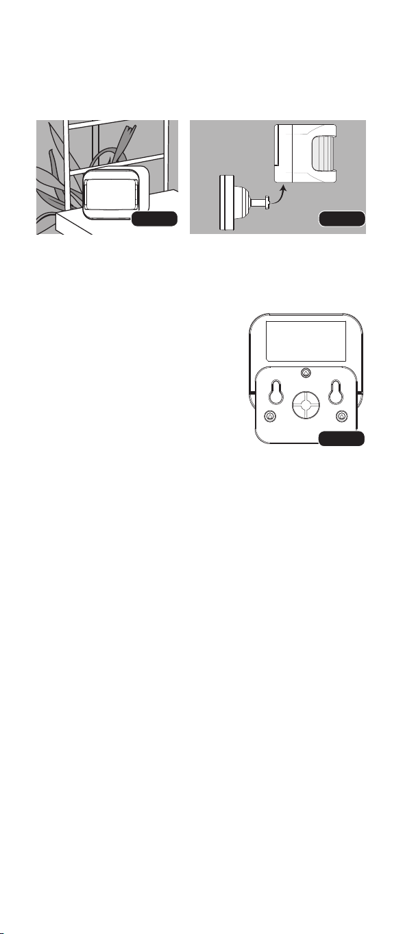
OPTION 1: USE MOTION SENSOR WITHOUT MOUNT
Place motion sensor on a shelf with the lens in the direction
that you want it to sense motion. For best results, ensure
that sensor is at desired level with no obstructions.
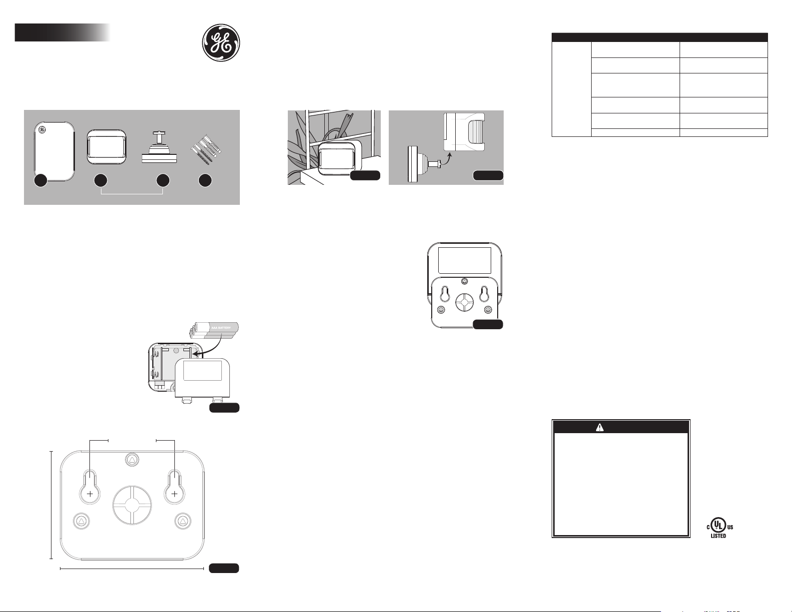
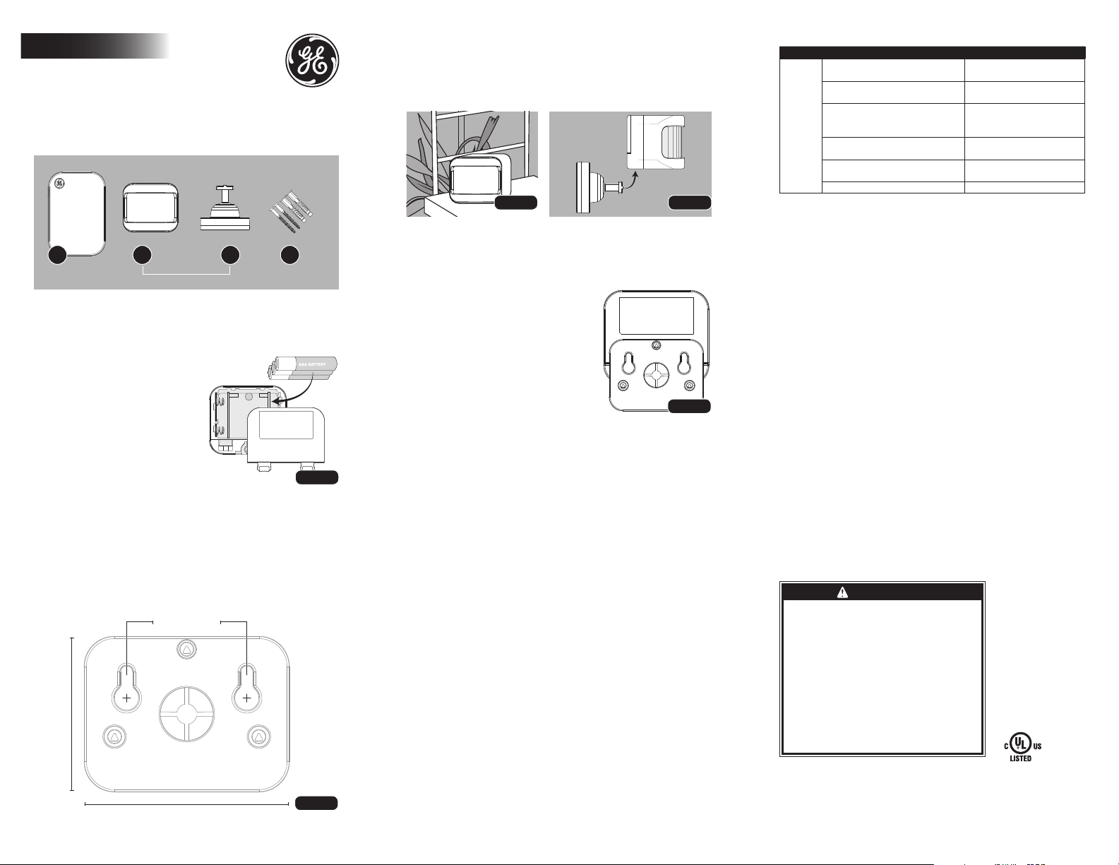
OPTION 2: WALL MOUNT WITH INCLUDED BRACKET
1. Turn motion sensor around
2. Line up mounting bracket with
slot on motion sensor.
NOTE: Mounting bracket only inserts
in one way [FIG.4] If it does not snap
together easily, turn bracket over.
3. Cut out mounting template [FIG.2].
4. Hold mounting template in desired
mounting location and mark wall where
screws will need to be installed.
5. If mounting directly to a stud, drill
holes using a 3/32” drill bit (anchors
will not be used). Be sure to leave
screw sticking 3/16” out of wall.
6. If mounting to drywall,
drill holes using a 1/4” drill bit. Gently tap in anchors. Be
sure to leave screw sticking 3/16” out of wall.
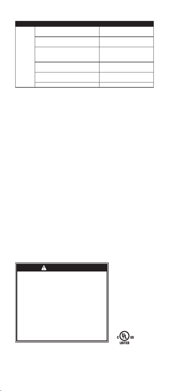
7. Hang motion sensor using keyholes on back of unit. Slightly tap into place.
8. Point motion sensor in your desired direction,
making sure there are no obstructions.
OPERATING INSTRUCTIONS
Lamp will turn on when motion is detected and turn off
after no motion is detected for 10 minutes.
PAIRING RECEIVER
(LIGHTING CONTROL COMES PAIRED IN THE PACKAGE. THIS SHOULD
ONLY BE NEEDED IF ADDING TRANSMITTERS AND/OR RECEIVERS
OR IF YOUR LIGHTING CONTROL HAS BECOME UNPAIRED.)
PAIRING — LINKING TRANSMITTER TO RECEIVER
1. Make sure receiver is unplugged.
2. Install 2 batteries and have the other one close by.
3. Plug in receiver and insert last battery into motion sensor within 8
seconds of plugging in receiver. Lamp will turn on briefly to indicate that
pairing was successful. After pairing is complete, motion sensor will go
into standard mode. Once triggered, the lamp will stay on for 10 minutes.
REPLACING BATTERIES
1. Remove motion sensor and mounting bracket from wall (if mounted).
2. Remove mounting bracket (if used).
3. Open battery door by pushing both tabs up at the same time
and pulling battery door away from product [FIG.1].
4. Insert new batteries, taking note of polarity markings on product.
5. Replace battery cover by inserting top of cover door in
notches first, then press door so that it snaps into place.
6. Re-attach mounting bracket (if mounting) [FIG.4].
7. Mount motion sensor back onto screws using
keyholes and tap into place (if mounting).
PLUG-IN RECEIVER
Functional Range ................................................................................................................ up to 150ft
Maximum Tungsten Load ..........................................................................................................360W
Maximum Resistive Load ........................................................................................................1440W
Rating .......................................................................................................................... 12A / 120V / 60Hz
TRANSMITTER
Functional Range ................................................................................................................ up to 150ft
Battery Type .......................................................................................................................................... AAA
* Functional range may be adversely affected by one or more of the
following factors: weather, radio frequency interference, low transmitter
battery and obstructions between the transmitter and receiver.
FCC STATEMENT
This device complies with Part 15 of the FCC and Industry Canada license-exempt
RSS standard(s). Operation is subject to the following two conditions: (1 this device
may not cause harmful interference, and (2) this device must accept any interference
received, including interference that may cause undesired operation.
FCC NOTE: The manufacturer is not responsible for any radio or TV
interference caused by unauthorized modifications to this equipment. Such
modifications could void the user’s authority to operate the equipment.
NOTE: This equipment has been tested and found to comply with the limits for a Class B
digital device, pursuant to Part 15 of the FCC Rules. These limits are designed to provide
reasonable protection against harmful interference in a residential installation. This
equipment generates, uses and can radiate radio frequency energy and, if not installed
and used in accordance with the instructions may cause harmful interference to radio
communications. However, there is no guarantee that interference will not occur in a
particular installation. If this equipment does cause harmful interference to radio or
television reception, which can be determined by turning the equipment off and on, the user
is encouraged to try to correct the interference by one or more of the following measures:
• Reorient or relocate the receiving antenna.
• Increase the separation between the equipment and receiver.
• Connect the equipment into an outlet on a circuit different
from that to which the receiver is connected.
• Consult the dealer or an experienced radio/TV technician for help.
CAN ICES-3(B)/NMB-3(B) | FCC: Q2I1612751 | IC 6924A-JP830771L8
ADDITIONAL RECEIVERS AND TRANSMITTERS AVAILABLE AT
MYSELECTSMART.COM
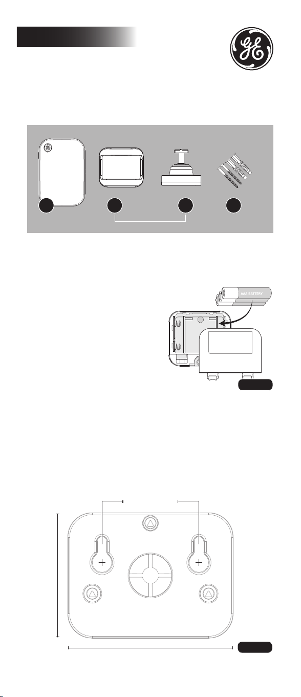
ENCLOSED YOU WILL FIND:
A. Plug-in receiver
B1. Motion-sensor
B2. Mounting bracket
C. Mounting screws and anchors
INSTALLATION INSTRUCTIONS (ON/OFF RECEIVER)
1. Plug lamp or the device to be controlled into
the outlet on the side of the receiver. Make sure
lamp or device is turned to the ON position.
2. Plug the receiver into a standard indoor outlet.
3. Wait 5 seconds for the receiver to activate.
IMPORTANT: It will take 5 seconds from the time the receiver is
plugged into the outlet before the motion sensor will be functional.
INSTALLING BATTERIES
(MOTION SENSOR) [FIG.1]
NOTE: 3 AAA type batteries required (not included).
1. Turn motion sensor around.
2. Push both tabs up at the same
time and pull battery door
away from product [FIG.1].
3. Install 3 AAA type batteries
(not included).
4. Replace battery cover by inserting
top of cover door in notches first, then
press door so that it snaps into place.
MOUNTING TEMPLATE [FIG.2]
Motion-activated Wireless
Lighting Control Manual
Indoor
A B1 B2 C
36235 V1
05/09/17 PM
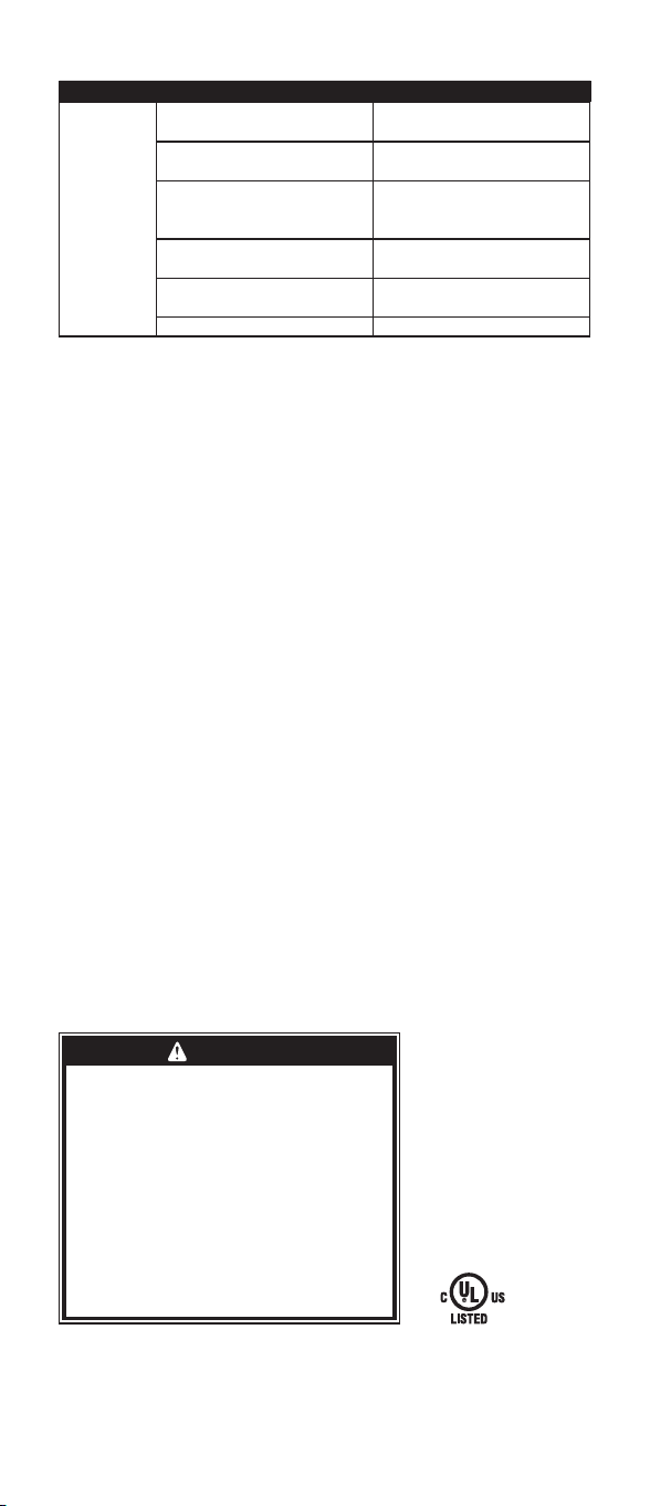
TROUBLESHOOTING
Problem Possible Cause Corrective Action
Light does
not turn ON.
Batteries in transmitter may
be installed incorrectly.
Verify the orientation of the
batteries, noting polarity.
Batteries in transmitter may
need to be replaced.
Replace all batteries
with new AAA type.
Lamp may not be turned on.
Ensure that lamp is turned
to the ON position and that
light bulb is working.
Motion sensor may have become
unpaired from receiver.
See “PAIRING RECEIVER” section.
Object may be between motion
sensor and movement.
Move object.
Receiver has become unplugged. Check the plug.
MADE IN CHINA
GE is a trademark of General Electric Company and is under license by
Jasco Products Company LLC, 10 E. Memorial Rd., Oklahoma City, OK 73114.
This Jasco product comes with a 1-year limited warranty.
Visit www.byjasco.com for warranty details.
Questions? Contact us at 1-800-654-8483 between 7:00AM—8:00PM CST.
BATTERIES MAY LEAK HARMFUL LIQUIDS OR IGNITABLE
MATERIALS OR EXPLODE CAUSING INJURY OR PRODUCT
DAMAGE.
• REPLACE FULLY DISCHARGED BATTERIES IMMEDIATELY
• REMOVE BATTERIES IF PRODUCT IS TO BE UNUSED FOR
EXTENDED PERIOD OF TIME
RISK OF ELECTRIC SHOCK
• FULLY INSERT PLUG
• KEEP CHILDREN AWAY
• USE INDOORS ONLY
• DO NOT USE IN WET LOCATIONS
• UNPLUG BEFORE CLEANING
RISK OF FIRE
• DO NOT EXCEED ELECTRICAL RATINGS
• DO NOT USE TO CONTROL MOTOR-OPERATED
APPLIANCES, TRANSFORMER-SUPPLIED APPLIANCES
OR APPLIANCES THAT CONTAIN HEATING ELEMENTS
(COOKERS, IRONS, HEATERS, ETC.)
WARNING
FIG.4FIG.3
FIG.1
FIG.5
FIG.2
1.54”
39.1mm
2.03”
51.5mm
1.18”
30mm
Patent Pending
MOUNTING OPTIONS
OPTION 1: USE MOTION SENSOR WITHOUT MOUNT
Place motion sensor on a shelf with the lens in the direction
that you want it to sense motion. For best results, ensure
that sensor is at desired level with no obstructions.
OPTION 2: WALL MOUNT WITH INCLUDED BRACKET
1. Turn motion sensor around
2. Line up mounting bracket with
slot on motion sensor.
NOTE: Mounting bracket only inserts
in one way [FIG.4] If it does not snap
together easily, turn bracket over.
3. Cut out mounting template [FIG.2].
4. Hold mounting template in desired
mounting location and mark wall where
screws will need to be installed.
5. If mounting directly to a stud, drill
holes using a 3/32” drill bit (anchors
will not be used). Be sure to leave
screw sticking 3/16” out of wall.
6. If mounting to drywall,
drill holes using a 1/4” drill bit. Gently tap in anchors. Be
sure to leave screw sticking 3/16” out of wall.
7. Hang motion sensor using keyholes on back of unit. Slightly tap into place.
8. Point motion sensor in your desired direction,
making sure there are no obstructions.
OPERATING INSTRUCTIONS
Lamp will turn on when motion is detected and turn off
after no motion is detected for 10 minutes.
PAIRING RECEIVER
(LIGHTING CONTROL COMES PAIRED IN THE PACKAGE. THIS SHOULD
ONLY BE NEEDED IF ADDING TRANSMITTERS AND/OR RECEIVERS
OR IF YOUR LIGHTING CONTROL HAS BECOME UNPAIRED.)
PAIRING — LINKING TRANSMITTER TO RECEIVER
1. Make sure receiver is unplugged.
2. Install 2 batteries and have the other one close by.
3. Plug in receiver and insert last battery into motion sensor within 8
seconds of plugging in receiver. Lamp will turn on briefly to indicate that
pairing was successful. After pairing is complete, motion sensor will go
into standard mode. Once triggered, the lamp will stay on for 10 minutes.
REPLACING BATTERIES
1. Remove motion sensor and mounting bracket from wall (if mounted).
2. Remove mounting bracket (if used).
3. Open battery door by pushing both tabs up at the same time
and pulling battery door away from product [FIG.1].
4. Insert new batteries, taking note of polarity markings on product.
5. Replace battery cover by inserting top of cover door in
notches first, then press door so that it snaps into place.
6. Re-attach mounting bracket (if mounting) [FIG.4].
7. Mount motion sensor back onto screws using
keyholes and tap into place (if mounting).
PLUG-IN RECEIVER
Functional Range ................................................................................................................ up to 150ft
Maximum Tungsten Load ..........................................................................................................360W
Maximum Resistive Load ........................................................................................................1440W
Rating .......................................................................................................................... 12A / 120V / 60Hz
TRANSMITTER
Functional Range ................................................................................................................ up to 150ft
Battery Type .......................................................................................................................................... AAA
* Functional range may be adversely affected by one or more of the
following factors: weather, radio frequency interference, low transmitter
battery and obstructions between the transmitter and receiver.
FCC STATEMENT
This device complies with Part 15 of the FCC and Industry Canada license-exempt
RSS standard(s). Operation is subject to the following two conditions: (1 this device
may not cause harmful interference, and (2) this device must accept any interference
received, including interference that may cause undesired operation.
FCC NOTE: The manufacturer is not responsible for any radio or TV
interference caused by unauthorized modifications to this equipment. Such
modifications could void the user’s authority to operate the equipment.
NOTE: This equipment has been tested and found to comply with the limits for a Class B
digital device, pursuant to Part 15 of the FCC Rules. These limits are designed to provide
reasonable protection against harmful interference in a residential installation. This
equipment generates, uses and can radiate radio frequency energy and, if not installed
and used in accordance with the instructions may cause harmful interference to radio
communications. However, there is no guarantee that interference will not occur in a
particular installation. If this equipment does cause harmful interference to radio or
television reception, which can be determined by turning the equipment off and on, the user
is encouraged to try to correct the interference by one or more of the following measures:
• Reorient or relocate the receiving antenna.
• Increase the separation between the equipment and receiver.
• Connect the equipment into an outlet on a circuit different
from that to which the receiver is connected.
• Consult the dealer or an experienced radio/TV technician for help.
CAN ICES-3(B)/NMB-3(B) | FCC: Q2I1612751 | IC 6924A-JP830771L8
ADDITIONAL RECEIVERS AND TRANSMITTERS AVAILABLE AT
MYSELECTSMART.COM
ENCLOSED YOU WILL FIND:
A. Plug-in receiver
B1. Motion-sensor
B2. Mounting bracket
C. Mounting screws and anchors
INSTALLATION INSTRUCTIONS (ON/OFF RECEIVER)
1. Plug lamp or the device to be controlled into
the outlet on the side of the receiver. Make sure
lamp or device is turned to the ON position.
2. Plug the receiver into a standard indoor outlet.
3. Wait 5 seconds for the receiver to activate.
IMPORTANT: It will take 5 seconds from the time the receiver is
plugged into the outlet before the motion sensor will be functional.
INSTALLING BATTERIES
(MOTION SENSOR) [FIG.1]
NOTE: 3 AAA type batteries required (not included).
1. Turn motion sensor around.
2. Push both tabs up at the same
time and pull battery door
away from product [FIG.1].
3. Install 3 AAA type batteries
(not included).
4. Replace battery cover by inserting
top of cover door in notches first, then
press door so that it snaps into place.
MOUNTING TEMPLATE [FIG.2]
Motion-activated Wireless
Lighting Control Manual
Indoor
A B1 B2 C
36235 V1
05/09/17 PM
TROUBLESHOOTING
Problem Possible Cause Corrective Action
Light does
not turn ON.
Batteries in transmitter may
be installed incorrectly.
Verify the orientation of the
batteries, noting polarity.
Batteries in transmitter may
need to be replaced.
Replace all batteries
with new AAA type.
Lamp may not be turned on.
Ensure that lamp is turned
to the ON position and that
light bulb is working.
Motion sensor may have become
unpaired from receiver.
See “PAIRING RECEIVER” section.
Object may be between motion
sensor and movement.
Move object.
Receiver has become unplugged. Check the plug.
MADE IN CHINA
GE is a trademark of General Electric Company and is under license by
Jasco Products Company LLC, 10 E. Memorial Rd., Oklahoma City, OK 73114.
This Jasco product comes with a 1-year limited warranty.
Visit www.byjasco.com for warranty details.
Questions? Contact us at 1-800-654-8483 between 7:00AM—8:00PM CST.
BATTERIES MAY LEAK HARMFUL LIQUIDS OR IGNITABLE
MATERIALS OR EXPLODE CAUSING INJURY OR PRODUCT
DAMAGE.
• REPLACE FULLY DISCHARGED BATTERIES IMMEDIATELY
• REMOVE BATTERIES IF PRODUCT IS TO BE UNUSED FOR
EXTENDED PERIOD OF TIME
RISK OF ELECTRIC SHOCK
• FULLY INSERT PLUG
• KEEP CHILDREN AWAY
• USE INDOORS ONLY
• DO NOT USE IN WET LOCATIONS
• UNPLUG BEFORE CLEANING
RISK OF FIRE
• DO NOT EXCEED ELECTRICAL RATINGS
• DO NOT USE TO CONTROL MOTOR-OPERATED
APPLIANCES, TRANSFORMER-SUPPLIED APPLIANCES
OR APPLIANCES THAT CONTAIN HEATING ELEMENTS
(COOKERS, IRONS, HEATERS, ETC.)
WARNING
FIG.4FIG.3
FIG.1
FIG.5
FIG.2
1.54”
39.1mm
2.03”
51.5mm
1.18”
30mm
Patent Pending
RECEPTOR PARA ENCHUFAR
Alcance operativo: .............................................................................................................hasta 150 pies (45,7 m)
Carga de tungsteno máxima: .........................................................................................................................360 W
Carga resistiva máxima: ...................................................................................................................................1440 W
Capacidad nominal: ................................................................................................................. 12 A / 120 V / 60 Hz
TRANSMISOR
Alcance operativo: .............................................................................................................hasta 150 pies (45,7 m)
Tipo de pilas: ........................................................................................................................................................................AAA
* El rango de funcionamiento podría verse afectado por uno o más de los siguientes
factores: clima, interferencia de frecuencia radial, pila baja del transmisor y
obstrucciones entre el transmisor y el receptor.
DECLARACIÓN DE LA COMISIÓN FEDERAL DE COMUNICACIONES (FCC)
Este dispositivo cumple con las especificaciones del apartado 15 de las normas de
la FCC y con las especificaciones de las normas radioeléctricas (RSS) del Ministerio
de Industria de Canadá aplicables a aparatos exentos de licencia. El funcionamiento
está sujeto a las siguientes dos condiciones: (1) este dispositivo no debe provocar
interferencia perjudicial, y (2) este dispositivo debe aceptar toda interferencia que
reciba, incluso la que pudiera causar un funcionamiento no deseado.
NOTA DE LA FCC: El fabricante no se hace responsable de ninguna interferencia radial
o televisiva ocasionada por modificaciones no autorizadas, efectuadas en este equipo.
Estas modificaciones podrían anular la autoridad del usuario para utilizar este equipo.
NOTA: Este equipo ha sido probado y cumple con los límites establecidos para dispositivos
digitales de Clase B, de conformidad con el apartado 15 de la normativa de la FCC.
Estos límites están diseñados para proveer protección razonable contra interferencias
perjudiciales en instalaciones residenciales. Este equipo genera, utiliza y puede irradiar
energía de radiofrecuencia. De no instalarse y utilizarse según las instrucciones, puede
provocar interferencia perjudicial a las radiocomunicaciones. No obstante, no es posible
garantizar que no se producirán interferencias en una determinada instalación. Si este
equipo provoca interferencia perjudicial a la recepción de radio o televisión, lo que
puede determinarse encendiendo y apagando el equipo, se recomienda al usuario
intentar corregir la interferencia a través de una o más de las siguientes medidas:
• Reorientar o reubicar la antena receptora.
• Incrementar la separación entre el equipo y el receptor.
• Conectar el equipo a un tomacorriente de un circuito diferente
del circuito al que está conectado el receptor.
• Consultar al distribuidor o a un técnico con experiencia en
radio/televisión para solicitar asistencia.
CAN ICES-3(B)/NMB-3(B) | FCC: Q2I1612751 | IC 6924A-JP830771L8
EN EL PAQUETE ENCONTRARÁ LO SIGUIENTE:
A. Receptor con enchufe
B1. Sensor de movimiento
B2. Soporte de montaje
C. Tornillos de montaje y fijaciones
INSTALAR LAS PILAS (SENSOR DE
MOVIMIENTO) [FIG.1]
NOTA: se necesitan 3 pilas tipo AAA (no incluidas).
1. Gire el sensor de movimiento.
2. Empuje ambas lengüetas hacia arriba
al mismo tiempo y retire la tapa del
compartimento de la pila [FIG.1].
3. Instale 3 pilas tipo AAA (no incluidas).
4. Reemplace la tapa del compartimento
para las pilas insertando primero
la parte superior de la tapa en las
muescas. Luego presione la puerta
para que encaje en su lugar.
INSTRUCCIONES PARA LA INSTALACIÓN (RECEPTOR ON/OFF)
1. Enchufe la lámpara o el dispositivo que desea controlar
en el tomacorriente que se encuentra en la parte
lateral del receptor. Asegúrese de que la lámpara
o el dispositivo esté encendido (posición ON).
2. Enchufe el receptor en un tomacorriente común para interiores.
3. Espere 5 segundos hasta que se active.
IMPORTANTE: Demora unos 5 segundos desde que se
enchufa el receptor en el sensor de movimiento.
PLANTILLA DE MONTAJE [FIG.2]
A B1 B2 C
FIG.2
OPCIONES DE MONTAJE
OPCIÓN 1: UTILIZAR EL SENSOR DE MOVIMIENTO SIN MONTARLO
Coloque el sensor de movimiento sobre un estante, con el objetivo en la
dirección que desea que detecte movimiento. Para obtener mejores resultados,
procure que el sensor quede ubicado en el nivel deseado, sin obstrucciones.
OPCIÓN 2: MONTAJE DE PARED CON SOPORTE INCLUIDO
1. Gire el sensor de movimiento
2. Alinee el soporte de montaje con la
ranura del sensor de movimiento.
NOTA: El soporte de montaje se inserta de una sola
manera. [FIG.4] Si no calza fácilmente, gire el soporte.
3. Recorte la plantilla de montaje [FIG.2].
4. Sujete la plantilla de montaje en la ubicación
que desee y marque en la pared los puntos
en los que se colocarán los tornillos.
5. Si la instalación se realiza directamente
en un pie derecho, haga las perforaciones
con una broca tamaño 3/32” (no
se utilizarán fijaciones). Asegúrese
de que el tornillo sobresalga 3/16” de la pared.
6. Si la instalación se realiza sobre un panel, haga las perforaciones
con una broca tamaño 1/4”. Golpee suavemente las fijaciones.
Asegúrese de que el tornillo sobresalga 3/16” de la pared.
7. Cuelgue el sensor de movimiento de los orificios con forma
de ojo de cerradura que se encuentran en la parte posterior
de la unidad. Cálcelo suavemente en su lugar.
8. Coloque el sensor de movimiento en la dirección deseada,
asegurándose de que no se produzcan obstrucciones.
INSTRUCCIONES DE FUNCIONAMIENTO
La lámpara se encenderá cuando se detecte movimiento y se
apagará si no se detecta movimiento durante 10 minutos.
ACOPLAR EL RECEPTOR
(EL CONTROL REMOTO DE LUCES YA VIENE ACOPLADO EN EL PAQUETE.
ESTE PROCEDIMIENTO SOLO SERÁ NECESARIO SI AGREGA TRANSMISORES
O RECEPTORES, O BIEN SI EL CONTROL DE LUCES SE DESACOPLA).
ACOPLAR: ENLAZAR EL TRANSMISOR CON EL RECEPTOR
1. Asegúrese de que el receptor esté desenchufado.
2. Instale dos baterías y tenga a mano la otra.
3. Conecte el receptor e inserte la última batería en el sensor de
movimiento a los ocho segundos de haber conectado el receptor. La
lámpara se encenderá brevemente para indicar que el acoplamiento
ha sido exitoso. Una vez que se haya producido el acoplamiento, el
sensor de movimiento se configurará en modo estándar. Una vez
activada, la lámpara quedará encendida durante 10 minutos.
CAMBIO DE PILAS
1. Retire el sensor de movimiento y el soporte de montaje
de la pared (en caso de que esté montado).
2. Retire el soporte de montaje (si es que se ha utilizado).
3. Abra el compartimento de la pila empujando ambas lengüetas hacia arriba
al mismo tiempo y extraiga el compartimento del producto [FIG.1].
4. Inserte las nuevas pilas, teniendo en cuenta las marcas de polaridad.
5. Reemplace la tapa del compartimento para las pilas insertando
primero la parte superior de la tapa en las muescas. Luego
presione la puerta para que encaje en su lugar.
6. Vuelva a colocar el soporte de montaje (en caso de estar montado) [FIG.4].
7. Monte el sensor de movimiento sobre los tornillos, utilizando las ranuras con
forma de ojo de cerradura y cálcelo en su lugar (en caso de que esté montado).
1.54”
39.1mm
2.03”
51.5mm
1.18”
30mm
Manual del
control remoto de luces
inalámbrico con cuenta regresiva
HECHO EN CHINA
GE es una marca comercial de General Electric Company con licencia otorgada a
Jasco Products Company LLC, 10 E. Memorial Rd., Oklahoma City, OK 73114.
Este producto de Jasco tiene una garantía limitada de 1 año.
Visite www.byjasco.com para conocer los detalles de la garantía.
¿Preguntas? Comuníquese al 1-800-654-8483 entre las 7:00
a. m. y las 8:00 p. m. CST (hora central estándar).
LAS PILAS PUEDEN PERDER LÍQUIDOS NOCIVOS O MATERIALES
INFLAMABLES, O BIEN EXPLOTAR Y CAUSAR LESIONES O DAÑAR
LOS PRODUCTOS.
• REEMPLACE LAS PILAS COMPLETAMENTE DESCARGADA DE
INMEDIATO.
• QUITE LAS PILAS SI NO USARÁ EL PRODUCTO DURANTE UN
PERÍODO PROLONGADO.
RIESGO DE DESCARGA ELÉCTRICA
• ENCHUFE COMPLETAMENTE LA CLAVIJA
• MANTENGA FUERA DEL ALCANCE DE LOS NIÑOS
• SOLO PARA USO EN INTERIORES
• NO UTILICE EN LUGARES HÚMEDOS
• DESCONECTE ANTES DE LIMPIAR
RIESGO DE INCENDIO
• NO SUPERE LOS VALORES NOMINALES ELÉCTRICOS
• NO UTILICE ESTE EQUIPO PARA CONTROLAR DISPOSITIVOS
QUE FUNCIONAN A MOTOR, ALIMENTADOS CON
TRANSFORMADOR O QUE INCLUYAN RESISTENCIA ELÉCTRICA
(COCINAS, PLANCHAS, CALEFACTORES, ETC.)
ADVERTENCIA
FIG.4FIG.3
FIG.5
FIG.1
RESOLUCIÓN DE PROBLEMAS
Problema Posibles causas Acción correctiva
La luz
no se
enciende.
Es posible que no se haya instalado
correctamente la pila en el transmisor.
Controle la orientación de las
pilas, en función de la polaridad.
Es posible que sea necesario
reemplazar la pila.
Reemplace todas las pilas
por una nueva pila AAA.
Puede ocurrir que la lámpara
no esté encendida.
Asegúrese de que la lámpara esté
ajustada en posición de encendido
y que la bombilla funcione.
Es probable que el sensor de movimiento
se haya desacoplado del receptor.
Consulte la sección
“ACOPLAR EL RECEPTOR”.
Puede haber un objeto que interfiere entre
el sensor de movimiento y el movimiento.
Mueva el objeto.
El receptor se ha desenchufado. Controle el enchufe.
Para interiores
Patente pendiente
RECEPTORES Y
TRANSMISORES
ADICIONALES DISPONIBLES
EN MYSELECTSMART.COM