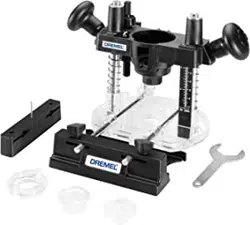
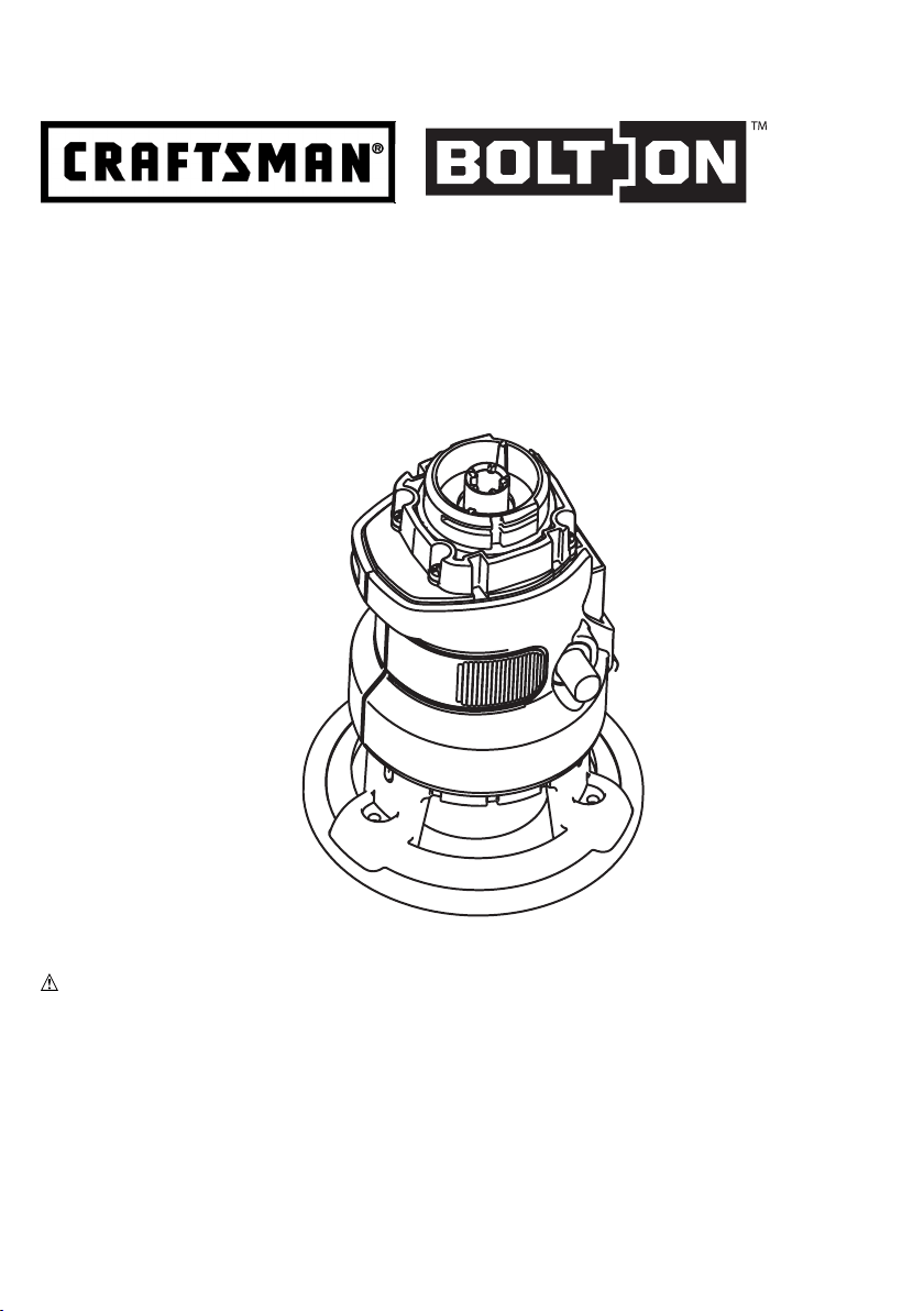
Router Attachment
Model: 34977
Sears Brands Management Corporation,
Hoffman Estates, IL 60179 U.S.A.
Read, understand and follow
all Safety Rules and Operating Instructions
in this manual before using this product.
See the full line of Craftsman
®
products
at craftsman.com
Part No. 90587571 JUNE 12
2
Read all safety warnings and all instructions. Failure to follow the
warnings and instructions may result in electric shock, re and/or serious injury.
Save all warnings and instructions for future reference.
Read all safety warnings and all instructions provided with your
Failure to follow the
warnings and instructions may result in electric shock, re and/or serious injury.
• Hold
Cutting a “live” wire may make exposed metal parts of the power tool “live” and shock the operator.
•
. Holding the
work by your hand or against the body leaves it unstable and may lead to loss of control.
• Keep handles dry, clean, and free from oil and grease. This will enable better control of the tool.
•
These
precautions will reduce the risk of personal injury.
K
uncontrolled router to lift up and out of the workpiece toward the operator.
•
cut. KICKBACK could cause the router to jump opposite the direction of the cut.
• Use sharp cutters. Dull cutters may cause the router to swerve or stall under pressure.
• It may be extremely hot.
defects in material or workmanship. With proof of purchase, a defective product will
www.craftsman.com
out from normal use within the warranty period.
services or if rented to another person.
which vary from state to state.
Sears Brands Management Corporation, Hoffman Estates, IL 60179
Indicates
May be used in conjunction with other symbols or pictographs.
Indicates hazardous situation which, if not avoided, will result in death or serious injury.
Indicates hazardous situation which, if not avoided, could result in death or
serious injury.
Indicates a haz ard ous situation which, if not avoided, could result in minor or
mod er ate injury or property damage.

3
• If the cutter head
is still spinning when the tool is laid down, it could cause injury or damage.
• If the bit is in contact
with the workpiece when the motor starts it could make the router jump, causing damage or injury.
•
•
• Use of larger than
recommended bits can result in a hazard.
•
•
•
: use safety glasses. Everyday eyeglasses are NOT safety glasses. Also use
face or dust mask if drilling operation is dusty. ALWAYS WEAR CERTIFIED SAFETY EQUIPMENT:
•ANSI Z87.1 eye protection (CAN/CPA Z94.3),
•ANSI S12.6 (S3.19) hearing protection,
•NOSH/OSHA respiratory protection.
:
construction activities contains chemicals known to the state of California to cause cancer,
•lead from lead-based paints,
• crystalline silica from bricks and cement and other masonry products, and
• arsenic and chromium from chemically-treated lumber.
Your risk from these exposures varies, depending on how often you do this type of work. To reduce
your exposure to these chemicals: work in a well ventilated area, and work with approved safety
equipment, such as those dust masks that are specially designed to lter out microscopic particles.
• Avoid prolonged contact with dust from power sanding, sawing, grinding, drilling, and other
Allowing dust to get into your mouth, eyes, or lay on the skin may promote absorption of harmful chemicals.
:
and permanent respiratory or other injury. Always use NOSH/OSHA approved respiratory
protection appropriate for the dust exposure. Direct particles away from face and body. Always
operate tool in well-ventilated area and provide for proper dust removal. Use dust collection
system wherever possible.
:
Under some conditions and duration of use, noise from this product may
contribute to hearing loss.
The label on your tool may include the following symbols. The symbols and their definitions are as follows:
V ................... volts A ................... amperes
Hz ................ hertz W .................. watts
min ............... minutes ................ alternating current
............ direct current
n
o.................. no load speed
................. Class I Construction .................. earthing terminal
(grounded) ................ safety alert symbol
................. Class II Construction .../min or rpm..... revolutions or reciprocation
(double insulated) per minute
............
Read instruction manual before use
.................. Use proper respiratory protection
................. Use proper eye protection .................. Use proper hearing protection
4
When using an extension cord, be sure to
use one heavy enough to carry the current
your product will draw. An undersized
cord will cause a drop in line voltage
resulting in loss of power and overheating.
The following table shows the correct
size to use depending on cord length and
nameplate ampere rating. If in doubt, use
the next heavier gage. The smaller the
gage number, the heavier the cord.
120V 0-25 26-50 51-100 101-150
(0-7,6m) (7,6-15,2m) (15,2-30,4m) (30,4-45,7m)
240V 0-50 51-100 101-200 201-300
(0-15,2m) (15,2-30,4m) (30,4-60,9m) (60,9-91,4m)
Ampere Rating
More Not more American Wire Gauge
Than Than
0 - 6 18 16 16 14
6 - 10 18 16 14 12
10 - 12 16 16 14 12
12 - 16 14 12 Not Recommended
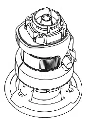
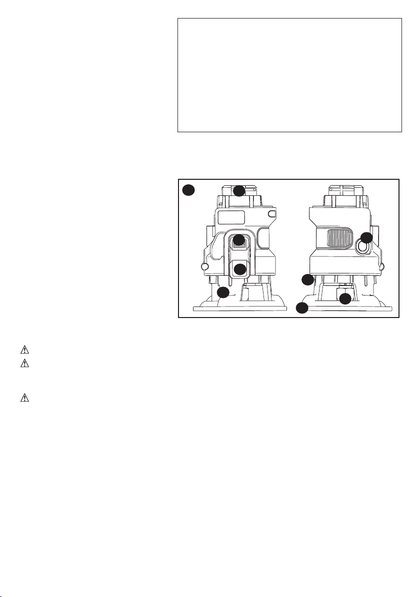
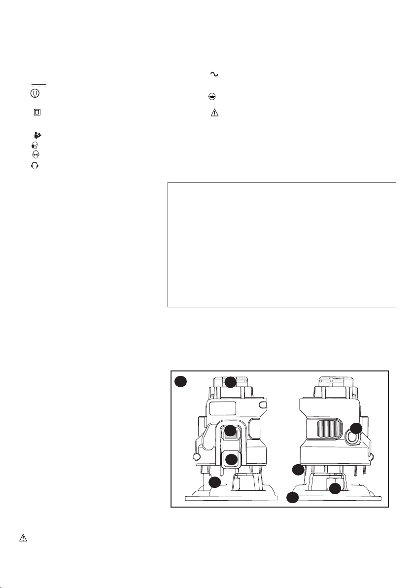
1. Router attachment
2. Spindle lock button
3. Active lock-Off button
4. Nut and Collet
5. Depth stop bar
6. Depth of cut scale
7. Chip shield
8. Base
Not shown:
Wrench
1
4
A
3
6
7
: Shock hazard. Under no circumstances should this product be used near water.
:
attachments or accessories.
: Do not touch work piece or bit immediately after
operating the tool. They can become very hot. Handle carefully. Always allow accessories and
workpiece to cool before handling.
Refer to Power Unit instruction manual before operating this tool for all safety warnings
and details on installing and removing attachments.
• Toswitchthetoolon,pressandholdtheactivelock-offbutton(3),thenfullypressthevariable
speed switch on the power unit. Once the bit begins to operate, release the active lock-off
button (3).
• Toswitchthetooloff,releasethevariablespeedswitch.
Operate the router at full speed at all times.
This attachment only operates in the forward direction, the forward/reverse slider of the
Power Unit should not be able to be switch to reverse.
5
:
•
•
•
:
:
source.
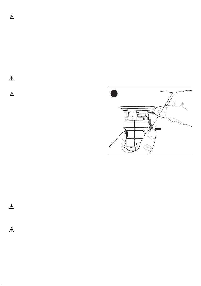
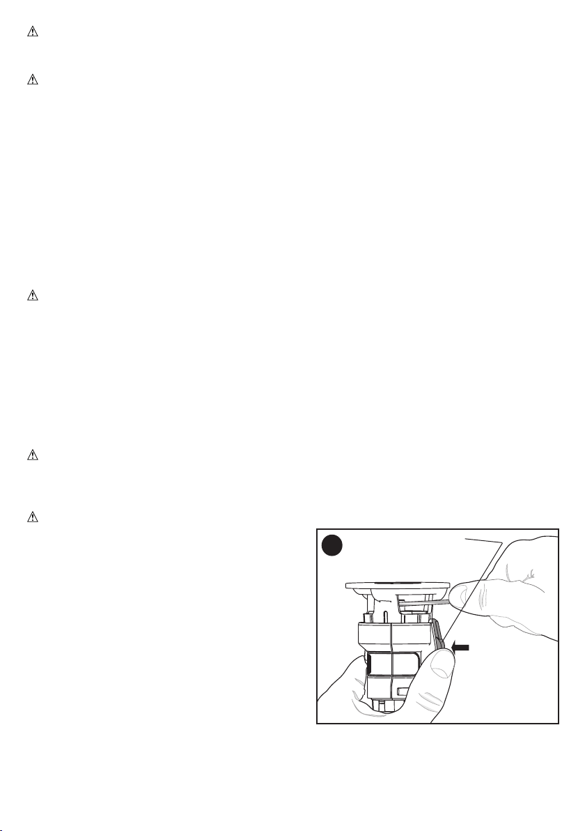
The router is equipped with a spindle lock feature
that makes changing bits easy. Lock the spindle
shaft by depressing the spindle lock button as shown
in and use the supplied wrench to loosen
(counterclockwise) the collet nut.
• Keepthespindlelockbutton(2)depressedandrotate
the spindle until the spindle lock fully engages.
• Placetherouterupsidedownonasmooth,flatsurface.
• Loosenthecolletnut(4)usingthewrenchprovided.
Insert the shank of the router bit into the collet (4).
• Wheninstallingrouterbits,besuretheyareinsertedasfaraspossibleandthenpulledoutabout
1/16” (1.5mm).
• Keepthespindlelockbutton(2)depressedandtightenthecolletnutclockwise(donotover-tighten)
using the wrench provided.
:
: Burn hazard.
• Keepthespindlelockbutton(2)depressed.
• Placetherouterupsidedownonasmooth,flatsurface.
• Loosen(counterclockwise)thecolletnut(4)usingthewrenchprovided.
• Releasebuttonandremovebit.
B

6
:
:
installing attachments or accessories.
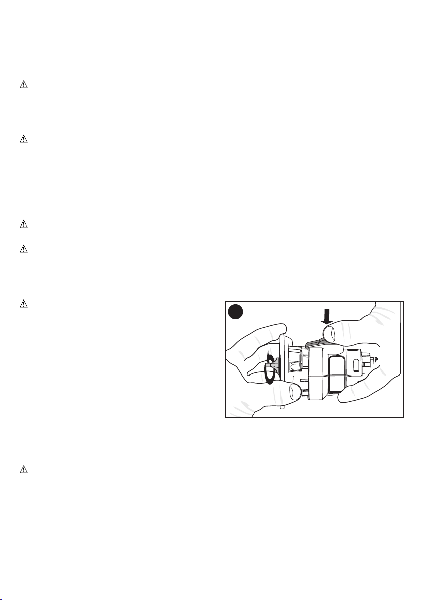
1.Keepthespindlelockbutton(2)depressedand
rotate the router base (8) as shown in .
Rotating the base clockwise will increase the routing
depth while rotating the base counterclockwise will
decrease the depth. Two complete revolutions of
the base equals about 2 millimeters.
2. After obtaining the desired routing depth, release the spindle lock button. Continue turning the
base until the notch under the spindle lock button (2) aligns with the next closest locking slot
in the depth of cut scale (6).
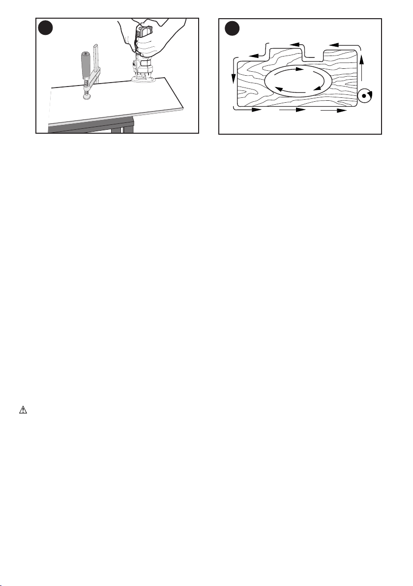
1. Make sure that the material to be cut is clamped down and is stable enough to support the
router during operation.
2. Use both hands on the power unit to control the router, and run the router at full speed at all
times. See
3. Move the router counterclockwise when cutting outside edges. Move clockwise when cutting
inside edges. See .
C
D
Router travel should follow arrows
E
Variation between materials and bit configurations dictates a wide variety of feed rates. Experience is
the best measure for determining feed rate. Become familiar with the sound and feel of the router by
making practice cuts in scrap material.
The router bit rotates at a very high speed and may heat up if the router is moved too slowly through
the wood and cause burn marks. Feeding the router too fast or trying to remove too much material in
a single pass will overload the motor. Use two or more passes for extra-large cuts (over 1/8” deep),
especially in hard woods.
7
When working on outside edges, move the tool counterclockwise (). When working on inside
edges, move the tool clockwise.
• Usepilot(ballbearing)routerbitsforedgeprofilecutting.
• UseHSS(highspeedsteel)routerbitsforsoftwood.
• UseTCT(tungstencarbidetipped)routerbitsforhardwood.
• Notrecommendedforplungecutting.
Use only mild soap and damp cloth to clean the tool. Never let any liquid get inside the tool; never
immerse any part of the tool into a liquid.
: To assure product SAFETY and RELIABILITY, repairs, maintenance, and adjustment
(other than those listed in this manual) should be performed by a qualified service dealer or other
qualified service personnel.
The use of any accessory not recommended for use with this tool could be hazardous.
Additional attachments and accessories for use with this tool are available at extra cost from your local
Sears store or Sears service center.
If you need assistance regarding accessories, please call:
.
•Attachmentwillnotstart. •Attachmentisnotsecured. •Makecertaintheattachmentisfullypushedinto
the Power Unit.
Refer to Power Unit instruction manual for troubleshooting solutions regarding operation of the
Power Unit.
8
instrucciones El incumplimiento de las advertencias e instrucciones puede
provocar descargas eléctricas, incendios o lesiones graves.
Conserve todas las advertencias e instrucciones para futuras consultas.
antes de
utilizar este accesorio. El incumplimiento de las advertencias e instrucciones
puede provocar una descarga eléctrica, un incendio y/o lesiones graves.
•
El contacto
con un cable con corriente eléctrica hará que las partes expuestas de la herramienta tengan
corriente y que el operador reciba una descarga eléctrica.
•
Sostener el trabajo con la mano o contra el cuerpo no brinda la estabilidad
requerida y puede llevar a la pérdida del control.
• Esto posibilitará un mejor
control de la herramienta.
•
Estas precauciones
reducirán el riesgo de lesiones personales.
Sears Brands Management Corporation, Hoffman Estates, IL 60179
Indica
. Se puede utilizan en conjunto con otros símbolos o pictografías.
Indica una situación de peligro, que de no evitarse, podría provocar la
muerte o lesiones graves.
Indica una situación de peligro, que de no evitarse, podría provocar
la muerte o lesiones graves.
Indica una situación de peligro, que de no evitarse, podría provocar
lesiones menores o moderadas o daños a la propiedad.

9
• Las cuchillas desafiladas pueden hacer que la sierra se desvíe o se
atasque al recibir presión.
• Puede estar
extremadamente caliente.
•
Dejar la herramienta cuando el cabezal de la cuchilla aún se encuentra girando puede causar una
lesión o un daño.
•
encender el motor. Si la broca está en contacto con la pieza de trabajo cuando se arranca el motor,
la broca podría saltar y esto ocasionaría una lesión o un daño.
•
•
•
•
herramienta en posición invertida.
•
•
caiga durante el uso.
: Los anteojos de uso diario
NO son lentes de seguridad. Utilice también máscaras faciales o para polvo si el corte produce
polvillo. UTILICE SIEMPRE EQUIPOS DE SEGURIDAD CERTIFICADOS:
•Protección para los ojos según la norma ANSI Z87.1 (CAN/CSA Z94.3)
•Protección auditiva según la norma ANSI S12.6 (S3.19)
•Protección respiratoria según las normas NIOSH/OSHA/MSHA
:
Algunos de estos productos químicos son:
•elplomodelaspinturasdebaseplomo,
•lasílicecristalinadeladrillos,elcementoyotrosproductosdemampostería,y
•elarsénicoyelcromodelamaderacontratamientoquímico.
El riesgo derivado de estas exposiciones varía según la frecuencia con la que se realice este tipo de
trabajo. Para reducir la exposición a estos productos químicos: trabaje en áreas bien ventiladas y
trabaje con equipos de seguridad aprobados, como las máscaras para polvo especialmente diseñadas
para filtrar las partículas microscópicas.
• Evite el contacto prolongado con el polvo procedente del lijado, serrado, esmerilado y taladrado
Si permite que el polvo se introduzca en la boca u ojos
o quede sobre la piel, puede favorecer la absorción de productos químicos peligrosos.
: El uso de esta herramienta puede generar o dispersar polvo lo cual
puede causar lesiones respiratorias serias y permanentes y otros tipos de lesión. Siempre use
protección respiratoria aprobada por NIOSH/OSHA para la exposición al polvo. Dirija las partículas
en dirección opuesta a su cara y cuerpo.
: Mientras use la herramienta, utilice la protección auditiva adecuada. En
10
•Laetiquetadesuherramientapuedeincluirlossiguientessímbolos.Lossímbolosy
sus definiciones son los siguientes:
V .................. voltios A ................amperios
Hz ................ hertz W ...............vatios
min .............. minutos ..............corriente alterna
............ corriente directa
n
o ...............no velocidad sin carga
................ Construcción Clase I
...............
terminal a tierra
(mis à la terre)
...............
Construcción de clase II .............simbolo de alerta
.../min .......... revoluciones o minuto seguridad
....... Lea el manual de instrucciones antes del uso
............Use protección adecuada para las vías respiratorias
............Use protección adecuada para los ojos
............Use protección adecuada para los oídos
•Cuandouseunalargador,
asegúrese de usar uno de un
calibre suficiente como para cargar
con la corriente que requerirá
su producto. Un alargador de
menor calibre causará una caída
en el voltaje de la línea lo que
resultará en pérdida de potencia y
sobrecalentamiento. El siguiente
cuadro muestra el tamaño correcto
a utilizar, dependiendo del largo del
cable y el amperaje nominal. En
caso de duda, utilice el de mayor
calibre. Mientras menor el número del calibre, mayor la capacidad del cable.
120V 0-25 26-50 51-100 101-150
(0-7,6m) (7,6-15,2m) (15,2-30,4m) (30,4-45,7m)
240V 0-50 51-100 101-200 201-300
(0-15,2m) (15,2-30,4m) (30,4-60,9m) (60,9-91,4m)
Au Au Calibre moyen des fils (AWG)
moins plus
0 - 6 18 16 16 14
6 - 10 18 16 14 12
10 - 12 16 16 14 12
12 - 16 14 12 Non recommandé
1. Aditamento de rebajadora
2. Botón de bloqueo del eje
3. Botón de bloqueo en apagado
4. Collar
5. Barra de tope de profundidad
6. Regla de profundidad de corte
7. Protector contra astillas
8. Base
1
4
A
3
6
7
: Bajo ninguna circunstancia utilice este
producto cerca de agua.
11
: Riesgo de laceraciones o quemaduras. No toque la pieza de trabajo ni la hoja
inmediatamente después de hacer funcionar la herramienta. Pueden calentarse mucho. Manipúlelas con
cuidado. Siempre espere a que los accesorios y la pieza de trabajo se enfríen antes de manipularlos.
: Para reducir el riesgo de lesiones, apague la herramienta y quítele la batería o
desconecte el enchufe de la fuente de alimentación antes de realizar cualquier ajuste o de quitar o instalar
aditamentos o accesorios. Quite todo accesorio del aditamento antes de quitar o instalar el aditamento.
Consulte el manual de instrucciones de la unidad motriz antes de utilizar esta herramienta
para conocer todas las advertencias y detalles sobre la instalación y extracción de aditamentos.
•Paraencenderlaherramienta,oprimaelinterruptordevelocidadvariable.Lavelocidaddela
herramienta depende de cuánto presione el interruptor.
•Paraapagarlaherramienta,suelteelinterruptordevelocidadvariable.
Este aditamento de la herramienta funciona únicamente en la dirección de avance; no debi-
era ser posible cambiar a reversa el interruptor deslizante de avance/reversa de la unidad motriz.
: Para reducir el riesgo de lesiones, apague la herramienta y quítele la
batería o desenchúfela de la fuente de alimentación antes de realizar cualquier ajuste o de
quitar o instalar aditamentos o cambiar brocas. De lo contrario, podría arrancar accidentalmente
y provocar lesiones.
:
:
el enchufe de la fuente de alimentación.
La rebajadora está equipada con una función de
bloqueo del eje que facilita los cambios de broca.
Sostenga el eje oprimiendo el botón de bloqueo del
ejecomosemuestraenlaguraByutilicelallave
provistaparaaojar(ensentidocontrarioalasagujas
del reloj) la tuerca del collar. Ajuste la tuerca del collar
rmementeensentidodelasagujasdelreloj.
• Mantengaoprimidoelbotóndebloqueodeleje(2)
y gire el eje hasta que el bloqueo del mismo quede
totalmente trabado.
• Coloquelarebajadoramirandohaciaarribasobre
unasupercieplanaylisa.
• Aojelatuercadelcollar(4)utilizandolallavepro-
vista. Inserte el vástago de la broca para rebajadora
en el collar (4).
• Asegúresedequeelvástagosobresalgaalmenos1,5mm(1/16pulgada)delcollar.
• Mantengaoprimidoelbotóndelbloqueodeleje(2)yajustelatuercadelcollarensentidodelas
agujas del reloj (no la ajuste en exceso) utilizando la llave provista.
B
12
A
A
• Mantengaoprimidoelbotóndelbloqueodeleje(2).
•Coloqueelrouteralrevéssobreunasupercielisayplana.
• Aoje(ensentidocontrarioalasagujasdelreloj)latuercadelcollar(4)utilizandolallaveprovista.
•Suelte el botón y quitar poco.
:
:
A
enchufe de la fuente de alimentación.
1. Oprima el botón de bloqueo del eje y gire la base
de la rebajadora como se muestra en la
C. Girar la base en sentido de las agujas del
reloj aumentará la profundidad de rebaje en tanto
que girar la base en sentido de las agujas del reloj
reducirá la profundidad. Dos giros completos de la
base equivalen a aproximadamente 2 milímetros.
2. Después de obtener la profundidad de rebaje
deseada, suelte el botón de bloqueo del eje. Siga
girando la base hasta que la muesca debajo del botón de bloqueo del eje quede alineada con la
siguiente ranura de bloqueo más cercana de la Regla de profundidad de corte (6).
:
enchufe de la fuente de alimentación.
1.Asegúresedequeelmaterialacortarestésujetormementeysucientementeestableparasoportar
la rebajadora durante el uso.
2. Utilice ambas manos sobre la unidad motriz para controlar la rebajadora y hágala funcionar a
velocidad máxima en todo momento. Consulte la .
3. Mueva la rebajadora en sentido contrario a las agujas del reloj al cortar bordes externos. Muévala
en sentido de las agujas del reloj al cortar bordes internos. Consulte la .
C
13
Lavariaciónentrematerialesylasconguracionesdelabrocaimponenunagranvariedaddeveloci-
dades de alimentación. La experiencia es la mejor medida para determinar la velocidad de aliment-
ación. Familiarícese con el sonido y sensación de la rebajadora mediante la realización de cortes de
práctica en material desechable.
La broca de la rebajadora gira a una muy alta velocidad y puede calentarse si la rebajadora se mueve
muy lentamente por la madera y podría dejar marcas de quemadura. Si se hace avanzar la rebajado-
ra muy rápidamente o si se intenta eliminar demasiado material en una sola pasada, el motor puede
sobrecargarse. Utilice dos o más pasadas para cortes extra grandes (más de (3,2 mm [1/8 pulgada]
de profundidad), especialmente en maderas duras.
Al trabajar en bordes externos, mueva la herramienta en sentido contrario a las agujas del reloj
(). Al trabajar en bordes internos, mueva la herramienta en sentido de las agujas del reloj.
• Utilicelospedacitosdelranuradordelpiloto(rodamientodebolitas)paraelcortedelperldelborde.
• Paramaderablanda,utilicebrocaspararebajadoradeacerodealtavelocidad(HSS).
• Paramaderadura,utilicebrocaspararebajadoraconpuntadecarburodetungsteno(TCT).
Utilice únicamente jabón suave y un trapo húmedo para limpiar la herramienta. Nunca permita que se
introduzcan líquidos en la herramienta; nunca sumerja ninguna parte de la herramienta en ningún líquido.
Para garantizar la SEGURIDAD y CONFIABILIDAD del producto, las reparaciones, el
mantenimiento y el ajuste (a excepción de los que no estén enumerados en este manual) deben ser
realizados por un centro de mantenimiento calificado u otro personal de mantenimiento calificado.
El uso de accesorios no recomendados para utilizar con esta herramienta
puede resultar peligroso.
Los aditamentos y accesorios adicionales para uso con esta herramienta están disponibles a un costo
adicional en la tienda local de Sears o el centro de mantenimiento local de Sears.
Si necesita ayuda con respecto a los accesorios, llame al:
.
Rotación del pedacito
E
D

14
• Launidadnoenciende. •Elaccesorionoestá
asegurado.
•Asegúresedeempujarporcompleto el
accesorio dentro de la unidad motriz.
Consulte el manual de instrucciones de la unidad motriz para conocer las soluciones a los
problemas relacionados con la operación de la unidad motriz.

15