Loading ...
Loading ...
Loading ...
888 User Guide
8
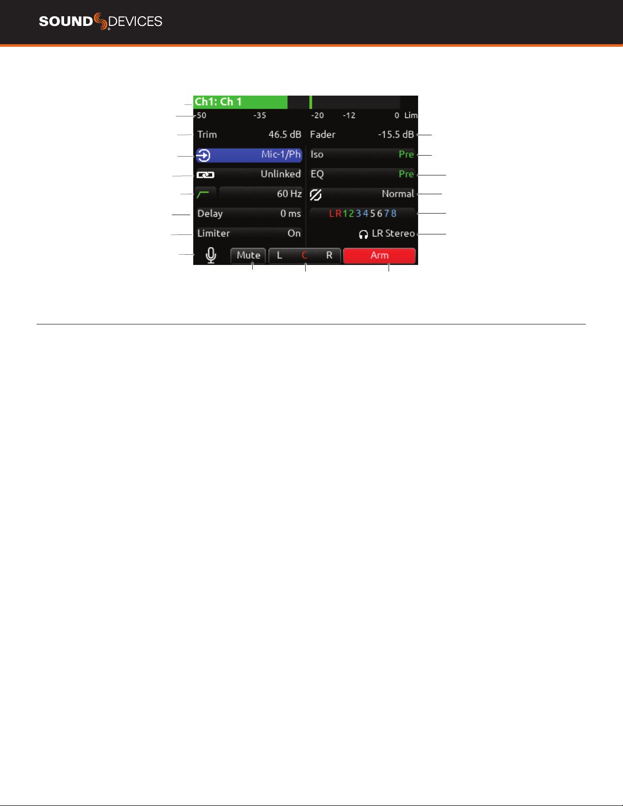
CHANNEL SCREEN
Channel designation
and user-dened name
Channel Meter view
Channel Trim value
Channel Arm
Channel to ISO routing
Channel Linking
Channel EQ
HPF (High Pass Filter) Polarity
Channel delay
Channel to Bus routing
Limiter
HP Preset
Channel Mute
L C R pan select
Channel Input selection
Slate Mic
Channel Fader Value
CHANNEL DESIGNATION AND USER-DEFINED NAME Indicates
the mixer channel designation and the user-dened name. Both are
overlaid onto the channel audio meter. When in a Channel Screen,
hold the PFL Switch for about 0.5 s to enter the virtual keyboard and
enter a user-dened name for the channel.
CHANNEL METER VIEW Indicates the audio level of the channel.
Metering follows ISO Routing selection, Pre- or Post-fade.
CHANNEL TRIM VALUE Indicates the gain of the channel trim con-
trol. The gain range depends on the type of input selected.
Mic: +12 to +76 dB
Line: -14 to +50 dB
Dante: -10 to +20 dB
AES3: -10 to +20 dB
AES42: 0 to +70 dB
Returns: -20 to +30 dB
CHANNEL FADER VALUE Indicates the level of the channel fader
control, continuously-variable from Off to +16 dB.
CHANNEL INPUT SELECTION Indicates which physical audio input
is feeding the channel.
ISO (CHANNEL->ISO) ROUTING Indicates where the isolated
track’s audio is tapped from in the audio chain. Pre-fade or Post-fade.
CHANNEL LINKING Indicates the current linking status. The linking
options are Unlinked, adjacent channels (e.g. 1,2) and adjacent chan-
nels Mid Side (e.g. 1-2MS). Linked parameters are: trims, faders, HPF,
delay, limiter, mute, ISO, Bus Send 1 and Bus Send 2. Stereo panning
is 1 to L and 2 to R. For MS linking, the pan becomes a balance con-
trol between Mid and Side.
CHANNEL EQ Indicates the EQ position in the audio chain. Pre(fade)
or Post(fade). Select to enter Channel EQ screen.
HPF (HIGH PASS FILTER) Indicates on/off status where green
icon and white value = ”On” and gray icon and value = “Off”. The HPF
frequency is variable in 10 Hz steps from 10 Hz to 320 Hz.
POLARITY REVERSE Indicates polarity status. Green icon = polarity
reversed, white icon = polarity normal.
CHANNEL INPUT DELAY Indicates input delay time. The input delay
is continuously-variable in milliseconds from 0-50 ms.
CHANNEL TO BUS ROUTING Determines to which bus or buses the
channel audio will be sent. When a channel is routed to a bus as a
Send (bus box highlighted blue), the Send Gain value is used. When
a channel is sent Pre (green) or Post (orange), the Send Gain value is
ignored.
CHANNEL LIMITER Indicates on/off status of channel limiter.
MUTE Indicates mute status of channel. Blue icon = muted. Toggle
mute on/off with the “Tone” switch.
L C R SELECT Indicates the stereo pan position of the channel’s
contribution to the L/R mix. Orange = selected. Use the */** switch
to select. Hold */** switch and rotate select knob for continuous
panning positioning. Alternatively, press and hold Select knob, then
use */** switch to pan continuously.
ARM Toggle the Rtn/Fav switch to arm or disarm isolated track for
recording.
HP PRESET Pressing in HP knob will toggle between HP preset
and PFL. Can be used to listen to channel panning while viewing the
Channel Screen by setting the HP Preset to LR Stereo.
Loading ...
Loading ...
Loading ...