888
PORTABLE PRODUCTION MIXER-RECORDER
Legal Notices
Product specications and features are subject to change without
prior notication.
Copyright
©
2019 Sound Devices, LLC. All rights reserved.
This product is subject to the terms and conditions of a
software license agreement provided with the product, and
may be used in accordance with the license agreement.
This document is protected under copyright law. An authorized
licensee of this product may reproduce this publication for the
licensee’s own personal use. This document may not be reproduced
or distributed, in whole or in part, for commercial purposes, such
as selling copies or providing educational services or support.
This document is supplied as a technical guide. Special care
has been taken in preparing the information for publication;
however, since product specications are subject to change,
this document might contain omissions and technical or
typographical inaccuracies. Sound Devices, LLC does not accept
responsibility for any losses due to the user of this guide.
Trademarks
The “wave” logo is a registered trademarks; SuperSlot, and
Wave Agent are trademarks of Sound Devices, LLC. Dante is
a registered trademark of Audinate. Windows and Microsoft
Excel are registered trademarks of Microsoft Corporation
in the U.S. and other countries. All other trademarks
herein are the property of their respective owners.
WEEE Statement
If you wish to discard a Sound Devices product in Europe,
contact Sound Devices (Germany) for further information.
Warning! This device can drive headphones to potentially
dangerous levels. Do not listen at high volume levels for
long periods.
Read and fully understand this manual before operation.
Manual Conventions
SYMBOL DESCRIPTION
>
This symbol is used to show the order in which you select menu
commands and sub-options, such as: Main Menu > Outputs
indicates you press the Menu button for the Main Menu, then
scroll to and select Outputs by pushing the Knob.
[ ] This symbol is used to convey selectable menu items.
* This symbol is used to convey factory default settings.
+
A plus sign is used to show button or keystroke combinations. For
instance, Ctrl+V means to hold the Control key down and press
the V key simultaneously. This also applies to other controls,
such as switches and knobs. For instance, MIC+HP turn means
to slide and hold the MIC/TONE switch left while turning the
Headphone (HP) knob. S+SELECT means to hold the METERS
button down as you press the SELECT knob.
Note
A
note
provides recommendations and important related
information. The text for notes appears italicized.
*
A cautionary warning about a specic action that could cause
harm to you, the device, or cause you to lose data. Follow the
guidelines in this document or on the unit itself when handling
electrical equipment. The text for cautionary notes also appears
italicized and bold in a different color.
DATE DESCRIPTION
10/25/19 v3.01 Initial release
Post Ofce Box 576
E7556 State Rd. 23 and 33
Reedsburg, Wisconsin 53959 USA
www.sounddevices.com
+1 608.524.0625 main
+1 608.524.0655 fax
800.505.0625 toll free
Included Accessories
PART NUMBER DESCRIPTION
2479.000 Cordset 6’ AC cable
9623.001 XL-WPTA4 power supply TA4 Connector
9244.003 LCD cover
9772.000 Antenna, SMA connector
5529.000 Promo Sticker (white)
5537.000 Promo sticker (black)
1312.000 Dot: Red, Yellow, Blue,Green, Purple, White (8 each)
888 User Guide | Rev 10/25/19
This document is distributed by Sound Devices, LLC in online electronic (PDF)
format only. Published in the USA.
This table provides the revision history and cross-reference
links to “what’s new” in this guide.

888 User Guide
1
Welcome to the 888
UNPRECEDENTED RECORDING POWER - ON A CART OR OVER THE SHOULDER.
Meet the 888 - the portable mixer-recorder that’s compact and light enough to use in a bag, yet has the high channel count and power required
for mobile cart productions. The 888 is the smallest portable mixer-recorder on the market that offers Dante for sending and receiving audio over
Ethernet. With 8 ultra low-noise, 8-Series microphone preampliers, 16 channels, 20 tracks, multiple powering methods, and support for multiple
USB control surfaces, the 888 can be easily tailored to your workow. An updated processing architecture and multiple FPGAs enables the 888 to
be fully routable: any physical input may be sent to any track, bus, or output.
Many features have carried over from the premium Sound Devices’ Scorpio, such as the new 8-Series preamplier design, 2 SD card slots, internal
256 GB SSD, and dual L-Mount battery charging and powering. Alternatively, power your 888 using a smart battery, NP-1 battery, or an in-line power
supply via its TA4 DC input. The ultra-accurate, fully-featured timecode generator contains its own battery to hold timecode for up to four hours after
power off.
Dedicated coms and slate allows for professional bi-directional communication with other crew members. Send customized mixes to the camera
or crew with multiple mix buses. With the ability to record to three media simultaneously, you can turn over an SD card to production, AAC les for
transcription, and keep a backup on the internal 256 GB SSD.
A built-in three band EQ may be set to either pre- or post-fade for each channel to tackle any problems directly on-set. Enable Dugan Automixing or
MixAssist to automatically attenuate unused microphones in multi-microphone applications. Up to 16 channels can be automixed at a time.
Get the perfect t on your cart with one of several supported USB control surfaces for remote fader and transport control. Download the companion
Android app, SD-Remote, to access to transport controls, metering, and sound reports on a large touch screen.
We are honored to be part of your kit.
Sincerely,
Sound Devices

888 User Guide
2
Table of Contents
FRONT PANEL 3
LEFT SIDE PANEL 4
RIGHT SIDE PANEL 5
REAR PANEL 6
TOP PANEL 6
HOME SCREEN 7
CHANNEL SCREEN 8
CHANNEL INPUT 9
VIRTUAL KEYBOARD 10
PHRASE MANAGER 11
CHANNEL EQ 12
MENUS 13
POWER MENU 14
CHANNEL SETUP 15
CHANNEL GROUPS 15
BUS MENU 16
OUTPUT MENU 17
HEADPHONE PRESETS 18
LIMITERS 18
AUTOMIXER 19
DUGAN AUTOMIX 19
MIXASSIST 20
METERS 21
TIMECODE 22
RECORD/PLAY 23
FILES 24
SLATE/COMS/RETURNS 27
SYSTEM 28
CONTROLLERS 29
TOGGLE SWITCH MENU 32
FRONT PANEL SHORTCUTS 32
TOGGLE SWITCH SHORTCUTS 33
USB KEYBOARD 34
SD REMOTE 35
QUICK SETUP 37
DANTE 38
SPECIFICATIONS 39
GLOSSARY 41
888 User Guide
3
Panel Views
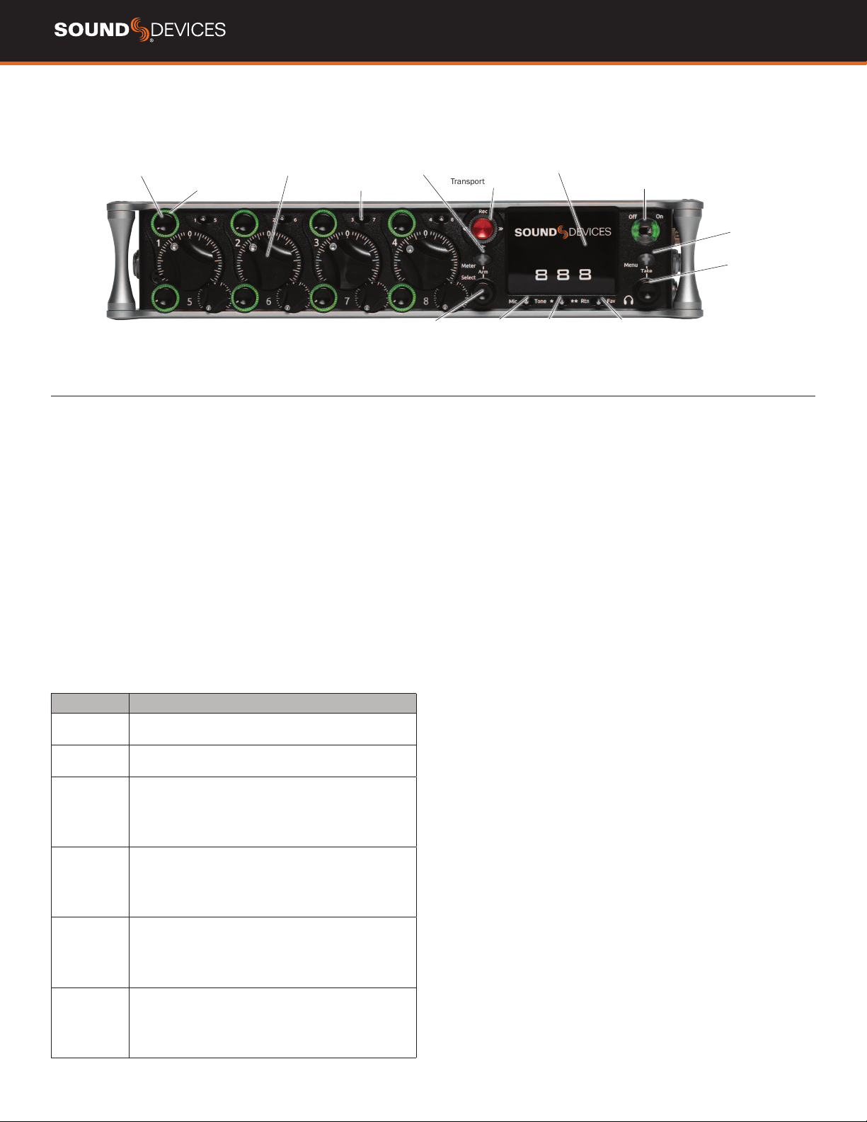
FRONT PANEL
Channel Trim
Channel Ring LED
Channel Fader
PFL Switch
Transport Control
LCD DisplayMeter Button
Select Knob
Mic/Tone Switch */** Switch Rtn/Fav Switch
Power Switch/LED Indicator
Menu Button
Headphone
Knob
CHANNEL TRIM Turns the channel on/off and sets the input sensi-
tivity for the channel. To conserve power, turn off unused channels by
rotating channel trim fully counterclockwise.
CHANNEL LED RING
Provides visual indication of channel signal
condition, solo and mute, and whether a channel is on or off.
CHANNEL FADER
Controls the audio level of the channel as it
contributes to the L/R mix and any destinations selected in routing as
“Post”.
PFL SWITCH
Pre/Post Fade Listen selects the channel in the head-
phones for Pre/Post Fade Listen while simultaneously entering the
channel screen. Also used for accessing virtual keyboard for channel
naming and various shortcuts.
TRANSPORT CONTROLS A joystick (with its illuminated LED ring)
on the front panel is used to perform various transport control func-
tions. (see table below). The ring LED will ash orange indicating post
roll while writing to media.
Function Action
Record Push up the Transport control to begin recording a new le.
The LED ring illuminates red while recording is underway.
Stop Press in the Transport control to stop recording or playback.
While in standby, press and hold to display next take name.
Play Push down on the Transport control to begin playback of the
last le recorded or le currently loaded. While in playback,
push down again to pause playback. The LED ring as well as
the active le in the display will ash to indicate that Pause
is active. Push down again to continue playback.
Rewind / Load
Previous Take
While in standby, push left to load the previous take. While
in playback, push and hold left to rewind.
When the 888 is playing back or paused, moving the joystick
to the left (<<) rewinds at 2x speed, then after holding for 5
seconds, it increases to 16x speed.
Fast Forward
/ Load Next
Take
While in standby, push right to load the next take. While in
playback, push and hold right to rewind.
When the 888 is playing back or paused, moving the joystick
to the right (>>) fast forwards at 2x speed, then after holding
for 5 seconds, it increases to 16x speed.
Scrub While playing or paused, press the headphone knob to
enter Scrub mode. Then rotate clockwise for fast forward or
counter-clockwise for rewind speeds of 0x, 1/8x, 1/4x, 1/2x,
1x, 2x, 4x, 8x, and 16x. The audio may be heard in scrub
mode up to 2x speed.
METER BUTTON Push to view and select various metering presets.
Used with Select knob. Press again to return to Home Screen. Push
with channel Select switched 1-8 for shortcut to Meters Preset 1-8.
SELECT KNOB
1. Push to view Outputs list, rotate and push to Select Output Screen.
Push Meter Button to return to Home Screen.
2. Rotate to select track in display, push both Meter and Select at
the same time to arm/disarm track. While holding the Meter Button,
multiple consecutive tracks may be armed by holding in the Select
knob and rotating.
3. Use with Meter Button to scroll through meter views then push to
Select.
4. Push with Channel Select switches 1-8 for shortcut to Bus 1-8, L,R
routing.
5. Menu navigation and push to Select.
MIC/TONE SWITCH Toggle slate mic and tone generator. Soft
button for menus.
*/** SWITCH Shortcut with PFL switch to access channels 9
through 16. Soft button for menus.
POWER SWITCH/LED INDICATOR Turns the power on and off.
Switch LED ring indicates the following:
1. Power condition: green = good, orange = warning, red = shutdown
imminent.
2. Flashing blue = power is off and holding timecode.
3. Continuous blue = booting up.
4. Flashing yellow = unit is off and charging L-mount batteries.
5. Continuous yellow = unit is off and both L-mount batteries are fully
charged.
MENU BUTTON Push to enter the Main menu. Also used to exit
menus. The Menu button will ash red to indicate clipping on the
headphones. Press with Channel Select switches 1-8 for shortcuts to
Menu Favorites 1-8.
HEADPHONE KNOB
1. Rotate to control headphone volume.
2. Press to open headphone preset menu and select.
3. Menu navigation and push to select.
4. Press Menu and HP Knob to enter Take List.
5. Press > 0.5s during playback to enter audio scrub mode.
Press with Channel Select switches 1-8 for shortcuts to HP Presets
1-8.
888 User Guide
4
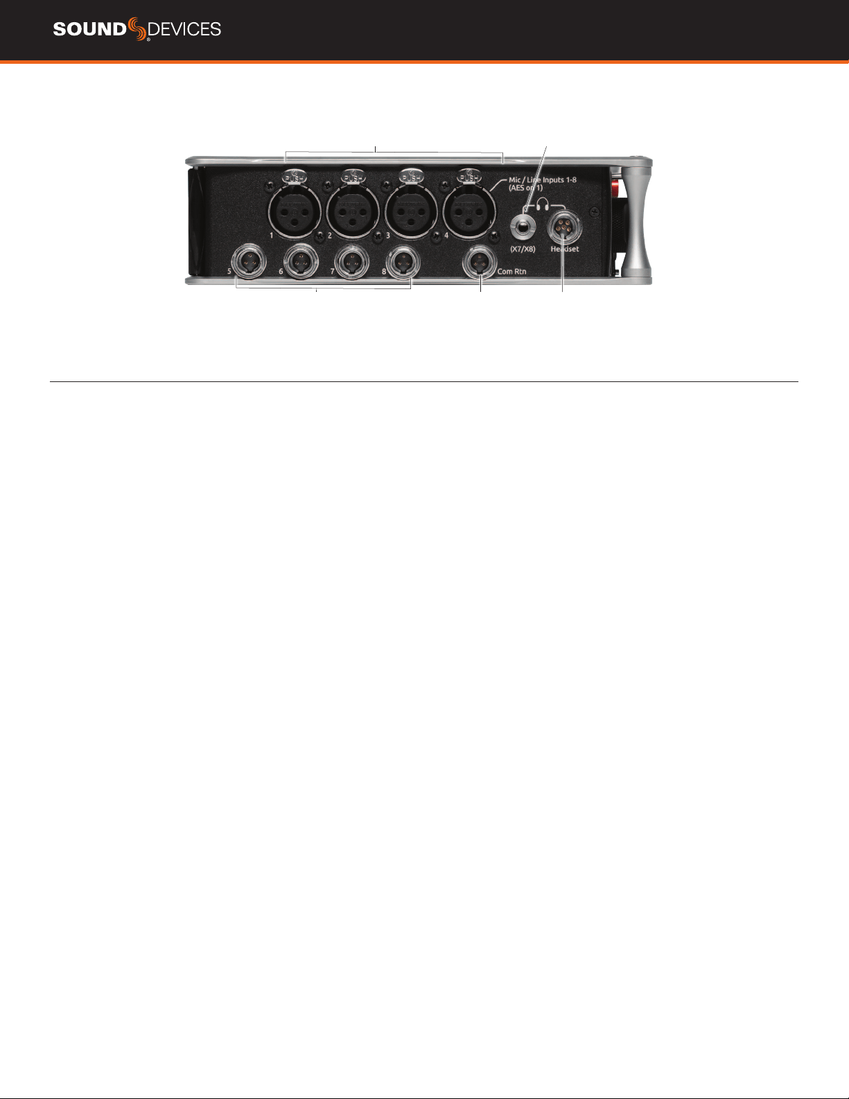
LEFT SIDE PANEL
Mic/Line Inputs 1-4 female XLR jacks
AES3/AES42 on XLR Input 1
Com Rtn TA3 jack
Headphone/(X7/X8) 3.5mm jack
Headphone/
Headset/External Slate
Mic TA5 jack
Mic/Line Inputs 5-8
TA3 jacks
INPUTS 1-4 FEMALE XLR JACKS Active-balanced analog micro-
phone or line-level inputs. Input 1 can also accept AES3 or AES42
signal. [pin-1 = ground, pin-2 = hot (+), and pin-3 = cold (-)]
MIC/LINE INPUTS 5-8 TA3 JACKS Active-balanced analog
microphone or line-level inputs. [pin-1 = ground, pin-2 = hot (+), pin 3
= cold (-)]
COM RTN TA3 JACK Balanced connection for Com Return audio
input. [pin-1 = Ground, pin-2 = hot (+), pin-3 = cold (-)]
HEADPHONE/(X7/X8) 3.5 MM JACK Unbalanced output and TRS
headphone output.
Warning! This output can drive headphones to po-
tentially dangerous levels.
Routing determined in the Outputs menu.
[Sleeve = ground, tip = left (X7), ring = right (X8)]
HEADPHONE/HEADSET TA5 JACK Headphone and slate micro-
phone connections [pin-1 = HP right, pin-2 = HP left, pin-3 = ground,
pin-4 = Mic -, pin-5 = Mic+]
888 User Guide
5
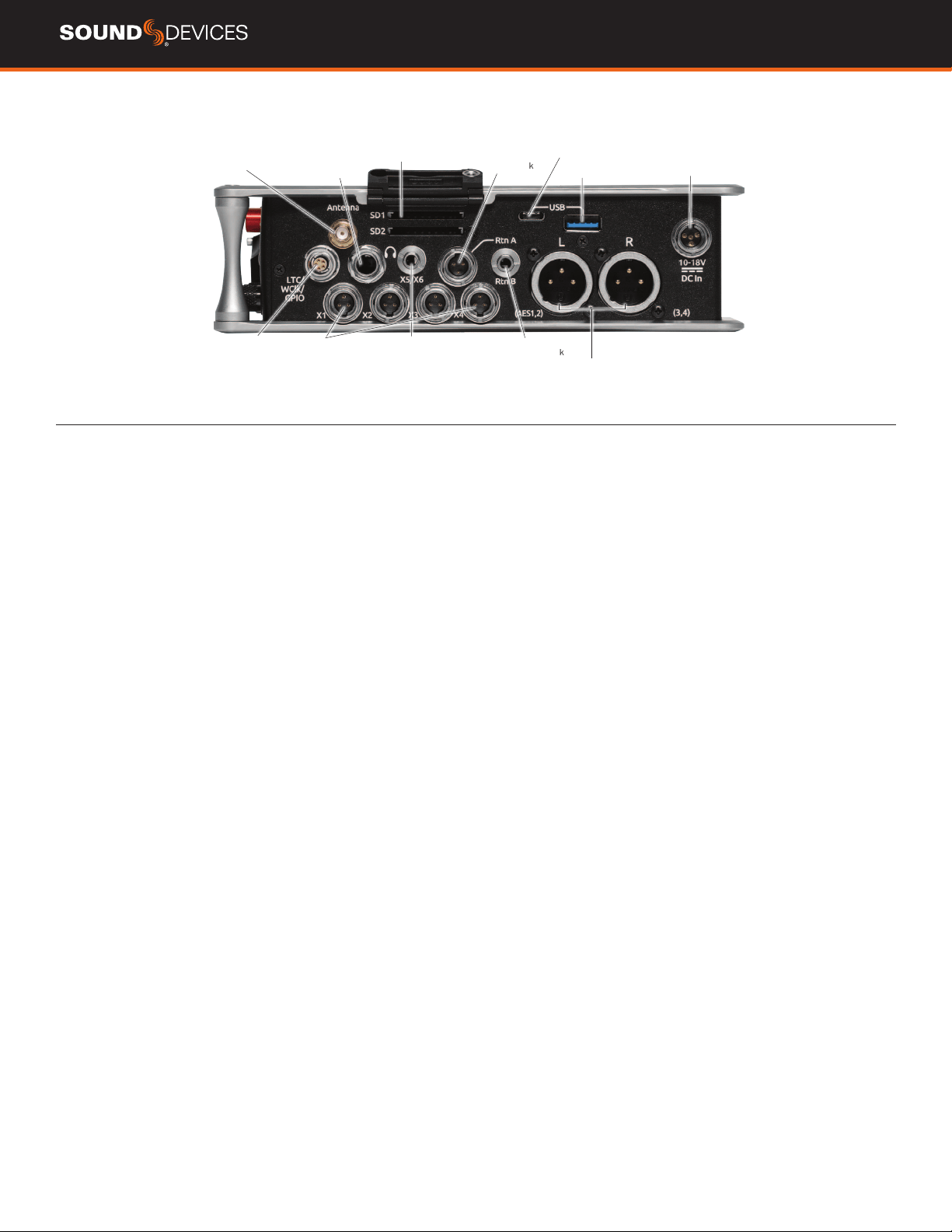
RIGHT SIDE PANEL
SD Card slots 1 & 2
Rtn A TA3 jack
USB C Port
USB A port
10-18 V DC TA4 jack
LTC/Wordclock/5-pin
LEMO jack
1/4” headphone jack
X5/X6 3.5
mm jack
Antenna SMA
connector
X1-X4
TA3 jacks
Rtn B
3.5 mm jack
Main Outputs L (AES 1,2),
R (AES 3,4) Male XLR jacks
ANTENNA RP-SMA-MALE CONNECTOR Connects to included
external antenna for Bluetooth LE.
¼” HEADPHONE JACK 1/4-inch TRS headphone output. Warning!
This output can drive headphones to potentially dangerous levels.
[Sleeve = ground, tip = left, ring = right]
SD 1 AND 2 CARD SLOTS Insert SD card media for recording.
Insert label side down.
RTN A TA3 JACK Unbalanced stereo TA3 connector for camera
return audio. [pin-1 = Ground, pin-2 = Left, pin-3 = Right]
USB C PORT
1. File transfer
USB A PORT
1. USB keyboard
2. USB to SD-Remote Android app
3. Sound Devices CL-12 Linear Fader Controller
4. USB to approved 3rd party fader controllers
10-18V DC TA4 JACK Accepts DC voltages from 10–18 V for
powering. [pin-1- GND, pin-2- Smart Battery DATA, pin-3- Smart
Battery CLOCK, pin-4- +10-18 VDC]
LTC/WORDCLOCK/5-PIN LEMO JACK Timecode I/O, Wordclock.
[pin-1- GND, pin-2- LTC or WORDCLOCK IN, pin-5- LTC or WORDCLOCK
OUT (Pins 2 and 5 are software selectable)]
X1-X4 TA3 JACKS Line, -10, or Mic level selected in Main menu
OUTPUTS section. Routing determined in the Outputs menu. [pin-1 =
Ground, pin-2 = hot (+), pin-3 = cold (-). Float pin-3 to un-balance]
X5/X6 3.5MM JACK Unbalanced stereo 3.5 mm female connector.
Routing determined in the Outputs menu. [Sleeve = ground, tip = X5,
ring = X6]
RTN B 3.5 MM JACK
Unbalanced stereo 3.5 mm female connector
for Return B audio input. [Sleeve = ground, tip = left, ring = right]
MAIN OUTPUTS L (AES 1,2), R (AES 3,4) XLR JACKS Analog
outputs on standard 3-pin XLR-3M connectors. Analog Output levels
are selected between Line, -10, and Mic levels in Main menu >
OUTPUTS. Can be set to send AES3 digital signals (1,2 and 3,4 on L
and R respectively) in Main menu > OUTPUTS. Routing determined in
the Outputs menu. [pin-1 = Ground; pin-2 = hot (+); pin-3 = cold (-).
Unbalance by oating pin-3]
888 User Guide
6
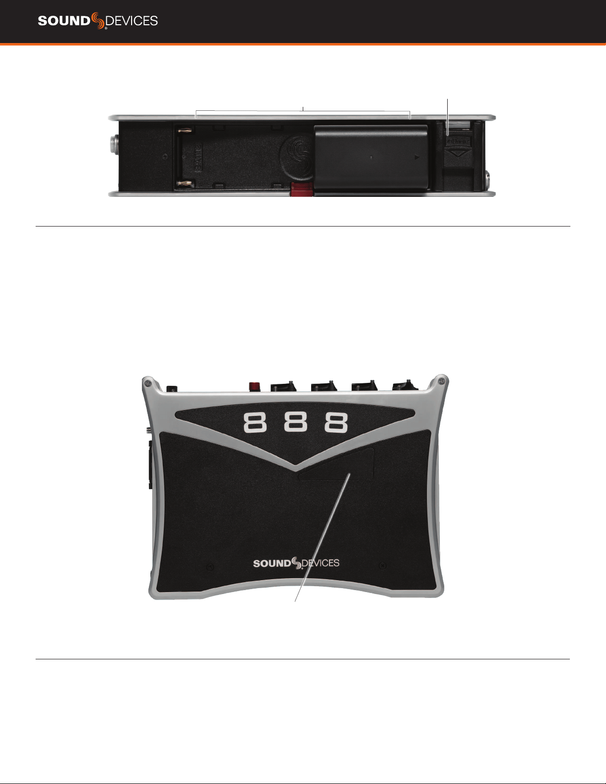
REAR PANEL
Battery 1, Battery 2 Docking
Dante /Ethernet RJ-45 jack
BATTERY 1, BATTERY 2 DOCKING Sony L-Mount type batteries
may be used. When connected to an external DC source the L-Mount
batteries can be charged if enabled in the Power menu.
DANTE RJ45 JACK 1 GbE port serving as a Dante audio network
connection. The Dante interface provides 16 inputs and 16 outputs
simultaneously. Routing is dened through the Channel Source and
Output menus. Dante Controller app on Mac/PC (from Audinate)
needed to route and use Dante.
TOP PANEL
Test connector for manufacturing
TEST CONNECTOR Used during manufacturing.
888 User Guide
7
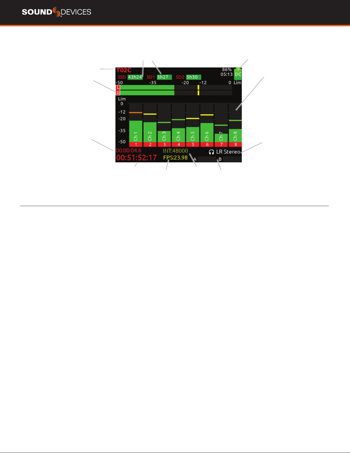
HOME SCREEN
Current take name
Media space
remaining indicators
LR mix bus meters
Individual channel
meters
File elapsed time
Selected
headphone preset
Timecode
Current frame rate
Temporary Level Display
Metering for
Returns A and B
Current sample rate
CURRENT TAKE NAME Shows the lename of the currently-
selected take.
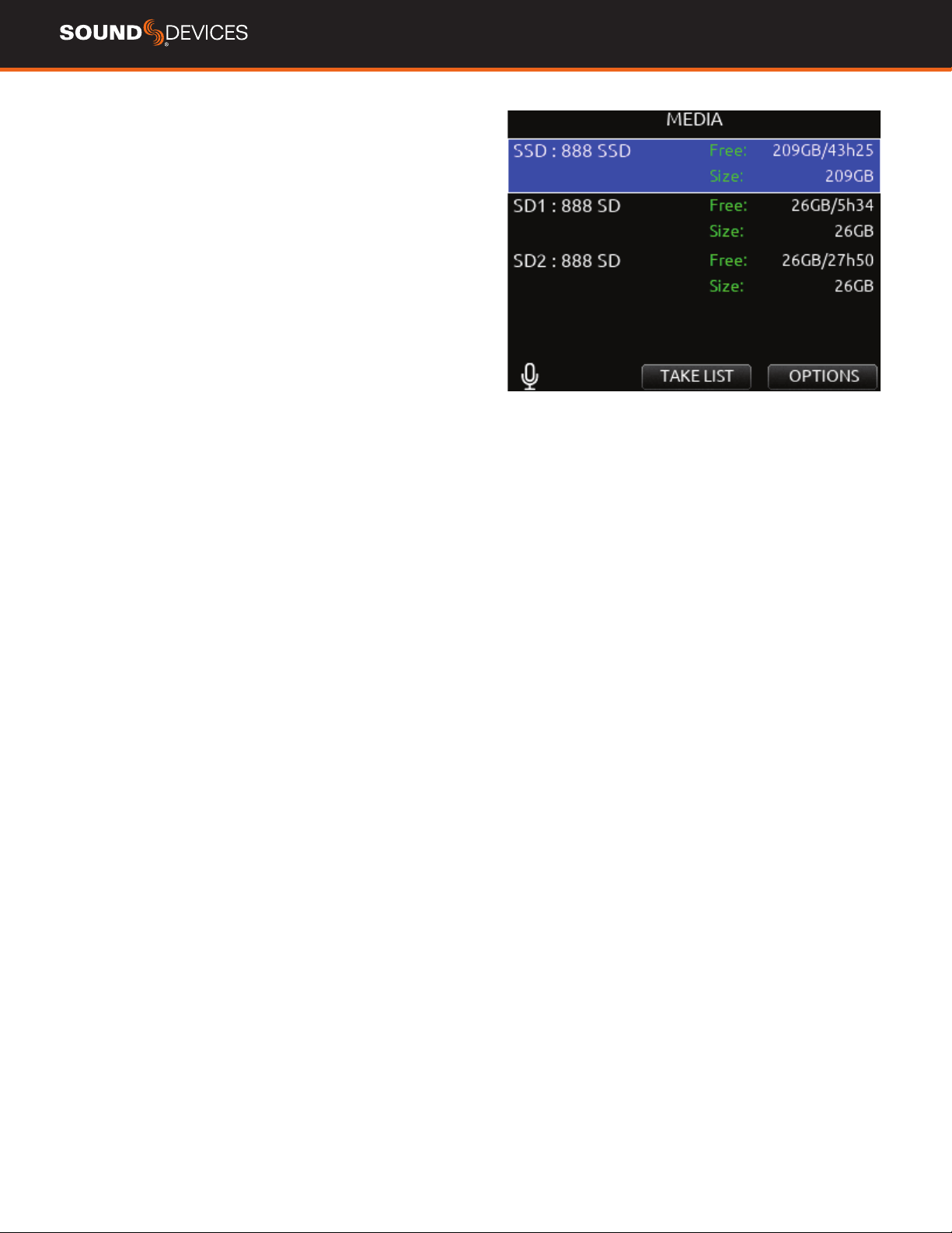
SSD, SD1, SD2 Indicates the amount of recording time available
based on current track count, sample rate, and media routing. The
internal SSD drive has a capacity of 256 GB.
POWER ICON Indicates approximate voltage condition and current
power source being used.
SMART BATTERY TELEMETRY Indicates time remaining and
percent remaining of Smart or Data Battery life. Other power sources
will show voltage.
LR MIX BUS METERS WITH ARM/DISARM INDICATION
Indicates the peak and VU audio levels of the L/R mix. The L and R
indicators turn red to indicate that the tracks are armed for record.
INDIVIDUAL CHANNEL METERS WITH ARM INDICATION Indi-
cates the peak and VU audio levels of the individual channel. May be
Pre- or Post- fade depending on Channel to ISO routing.
FILE ELAPSED/ REMAINING TIME Indicates in
Hours:Minutes:Seconds:1/10ths the elapsed time of the current le.
During playback, displays the elapsed and remaining time in hours,
minutes and seconds.
TIMECODE Indicates current SMPTE timecode value.
SAMPLE RATE / FRAME RATE/ TEMPORARY LEVEL DISPLAY
1. Indicates current sample rate.
2. Indicates current frame rate.
3. Temporarily indicates fader level of last moved fader (red text box).
4. Temporarily indicates trim level of last moved trim (green text box).
5. Temporarily indicates bus level of last adjusted bus fader (light blue
text box).
6. Temporarily indicates output level of last adjusted out gain (white
text box).
7. Temporarily indicates EQ freq and gain of last adjusted EQ (blue
text box when EQ is On, orange text box when EQ is off or band is
bypassed).
SELECTED HEADPHONE PRESET Indicates the currently-selected
headphone preset.
METERING FOR RETURNS A AND B Indicates audio level for the
returns.
Power icon and
smart battery telemetry
888 User Guide
8
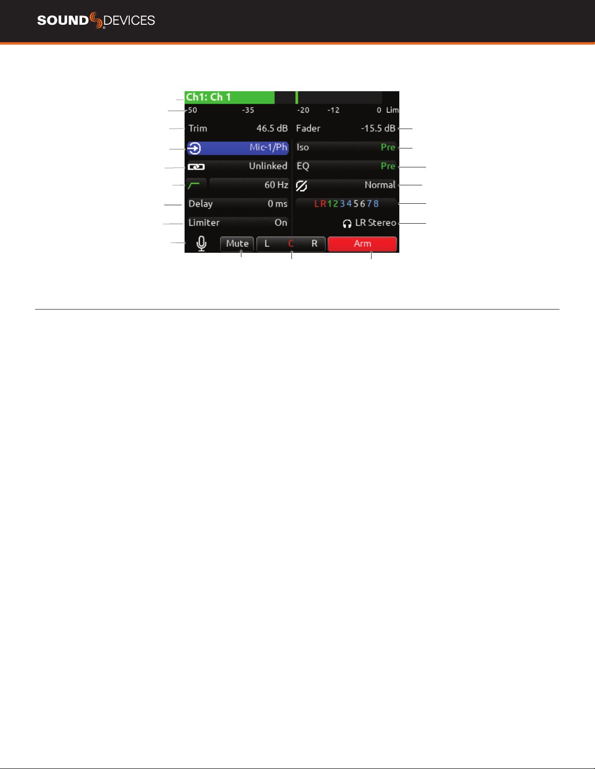
CHANNEL SCREEN
Channel designation
and user-dened name
Channel Meter view
Channel Trim value
Channel Arm
Channel to ISO routing
Channel Linking
Channel EQ
HPF (High Pass Filter) Polarity
Channel delay
Channel to Bus routing
Limiter
HP Preset
Channel Mute
L C R pan select
Channel Input selection
Slate Mic
Channel Fader Value
CHANNEL DESIGNATION AND USER-DEFINED NAME Indicates
the mixer channel designation and the user-dened name. Both are
overlaid onto the channel audio meter. When in a Channel Screen,
hold the PFL Switch for about 0.5 s to enter the virtual keyboard and
enter a user-dened name for the channel.
CHANNEL METER VIEW Indicates the audio level of the channel.
Metering follows ISO Routing selection, Pre- or Post-fade.
CHANNEL TRIM VALUE Indicates the gain of the channel trim con-
trol. The gain range depends on the type of input selected.
Mic: +12 to +76 dB
Line: -14 to +50 dB
Dante: -10 to +20 dB
AES3: -10 to +20 dB
AES42: 0 to +70 dB
Returns: -20 to +30 dB
CHANNEL FADER VALUE Indicates the level of the channel fader
control, continuously-variable from Off to +16 dB.
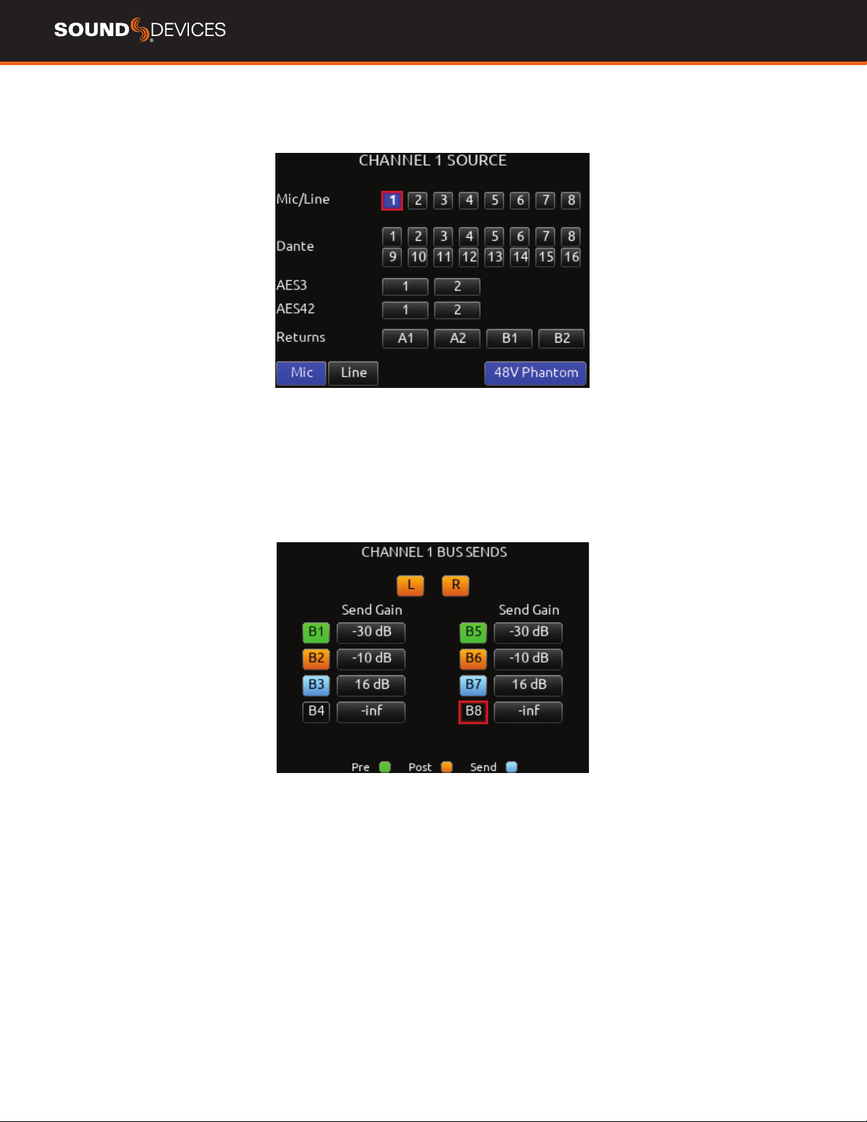
CHANNEL INPUT SELECTION Indicates which physical audio input
is feeding the channel.
ISO (CHANNEL->ISO) ROUTING Indicates where the isolated
track’s audio is tapped from in the audio chain. Pre-fade or Post-fade.
CHANNEL LINKING Indicates the current linking status. The linking
options are Unlinked, adjacent channels (e.g. 1,2) and adjacent chan-
nels Mid Side (e.g. 1-2MS). Linked parameters are: trims, faders, HPF,
delay, limiter, mute, ISO, Bus Send 1 and Bus Send 2. Stereo panning
is 1 to L and 2 to R. For MS linking, the pan becomes a balance con-
trol between Mid and Side.
CHANNEL EQ Indicates the EQ position in the audio chain. Pre(fade)
or Post(fade). Select to enter Channel EQ screen.
HPF (HIGH PASS FILTER) Indicates on/off status where green
icon and white value = ”On” and gray icon and value = “Off”. The HPF
frequency is variable in 10 Hz steps from 10 Hz to 320 Hz.
POLARITY REVERSE Indicates polarity status. Green icon = polarity
reversed, white icon = polarity normal.
CHANNEL INPUT DELAY Indicates input delay time. The input delay
is continuously-variable in milliseconds from 0-50 ms.
CHANNEL TO BUS ROUTING Determines to which bus or buses the
channel audio will be sent. When a channel is routed to a bus as a
Send (bus box highlighted blue), the Send Gain value is used. When
a channel is sent Pre (green) or Post (orange), the Send Gain value is
ignored.
CHANNEL LIMITER Indicates on/off status of channel limiter.
MUTE Indicates mute status of channel. Blue icon = muted. Toggle
mute on/off with the “Tone” switch.
L C R SELECT Indicates the stereo pan position of the channel’s
contribution to the L/R mix. Orange = selected. Use the */** switch
to select. Hold */** switch and rotate select knob for continuous
panning positioning. Alternatively, press and hold Select knob, then
use */** switch to pan continuously.
ARM Toggle the Rtn/Fav switch to arm or disarm isolated track for
recording.
HP PRESET Pressing in HP knob will toggle between HP preset
and PFL. Can be used to listen to channel panning while viewing the
Channel Screen by setting the HP Preset to LR Stereo.
888 User Guide
9
CHANNEL INPUT SOURCE
CHANNEL BUS SENDS
888 User Guide
10
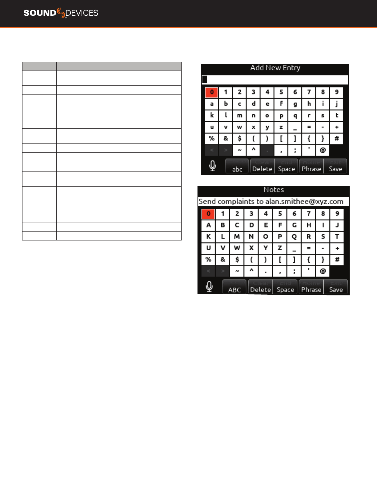
Virtual Keyboard
Action Function
Rotate HP Scrolls orange highlight through the keyboard
characters.
Press HP Inserts the highlighted character in text eld.
‘abc’ switch Quick ick toggles between A-Z and a-z in keyboard.
Hold ‘abc’
switch
Momentary selection of other case.
Delete Deletes character to the left of ashing cursor.
Hold Delete Repeatedly deletes characters to the left of ashing
cursor.
Space Inserts space at the ashing cursor position.
Hold Space Repeatedly inserts spaces.
Save switch Saves text and exits screen.
Rotate
Select
Moves the cursor to the left or right in the text eld.
Quick Press
Select
Switches to the Shifted functions: Clear, End, Home,
Exit. When shifted functions are active, their text
changes to white and the non-shifted functions
change to gray.
Clear Clears text from the text edit eld.
End/Home Moves cursor to end/start of text.
Exit Exits screen without saving text edits.
888 User Guide
11
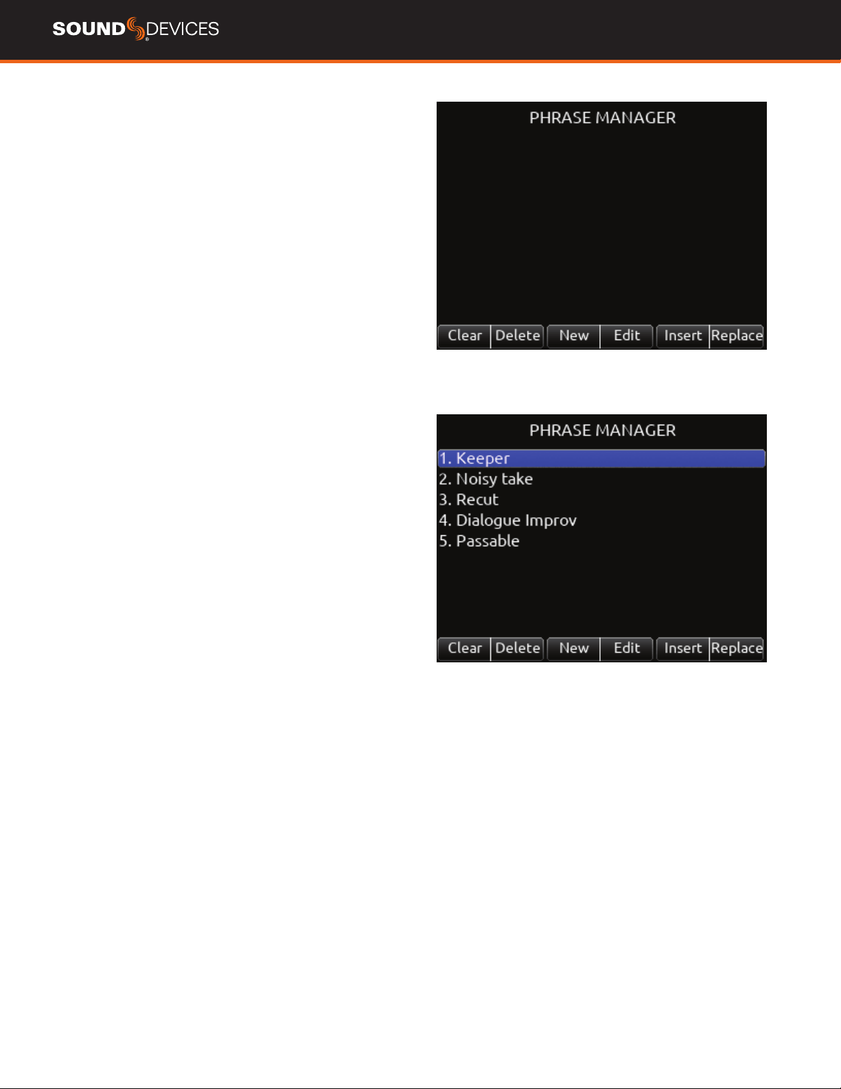
Phrase Manager
CLEAR Clears all phrases.
DELETE Deletes selected phrases.
NEW Create new phrase.
EDIT Edit selected phrase.
INSERT Inserts selected phrase into text.
REPLACE Replaces text with current selected phrase.
888 User Guide
12
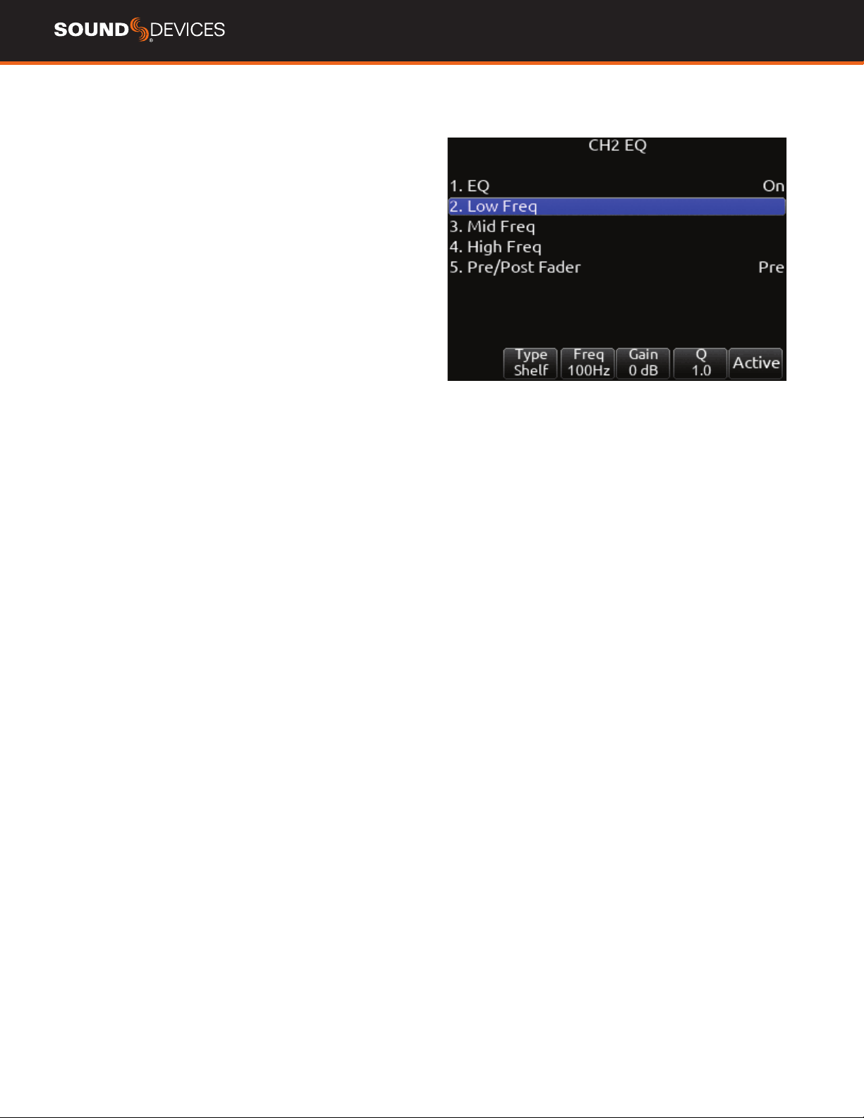
Channel EQ
1. EQ Selects channel EQ state. [Off*, On]
2. LOW FREQ Selects low frequency EQ lter parameters.
a. Type- Indicates Shelf or Peaking lter. [Shelf, Peak]
b. Freq- Indicates frequency of the lter, continuously-variable from
20 Hz to 20 kHz (100Hz*).
c. Gain- Indicates gain of the lter, continuously-variable from -15 dB
to +15 dB in 1 dB increments (0 dB*).
d. Q- Indicates “Q” or bandwidth of the lter, continuously-variable
from .5 - 10 in .1 increments (1.0*).
e. Bypass- Indicates state of the lter. [Bypass (orange ll)]*
3. MID FREQ Selects mid frequency EQ lter parameters.
a. Freq- Indicates frequency of the lter, continuously-variable from
200-20 kHz in 10 Hz increments (5000Hz*).
b. Gain- Indicates gain of the lter, continuously-variable from -15 dB
to +15 dB in 1 dB increments (0 dB*).
c. Q- Indicates “Q” or bandwidth of the lter, continuously-variable
from .5-10 in .1 increments (1.0*).
d. Bypass- Indicates state of the lter [Bypass(orange ll)]*.
4. HI FREQ Selects high frequency EQ lter parameters.
a. Type- Indicates Shelf or Peaking lter [Peak, Shelf]
b. Freq- Indicates frequency of the lter, continuously-variable from
20 Hz to 20 kHz. (100 Hz*).
c. Gain- Indicates gain of the lter, continuously-variable from -15 dB
to +15 dB in 1 dB increments. (0 dB*)
d. Q- Indicates “Q” or bandwidth of the lter, continuously-variable
from .5 - 10 in .1 increments. (1.0*)
e. Bypass- Indicates state of the lter. [Bypass (orange ll)]*
5. PRE/POST-FADER Indicates where the EQ is inserted into the
audio chain. Pre-fade or Post-fade. [Pre*, Post]
EQ will apply to bus sends when applied Pre-fade only
.
888 User Guide
13
Menus
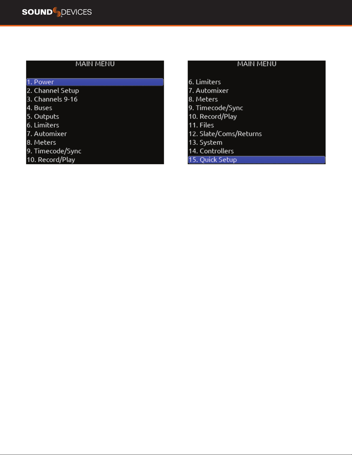
MAIN MENU
888 User Guide
14
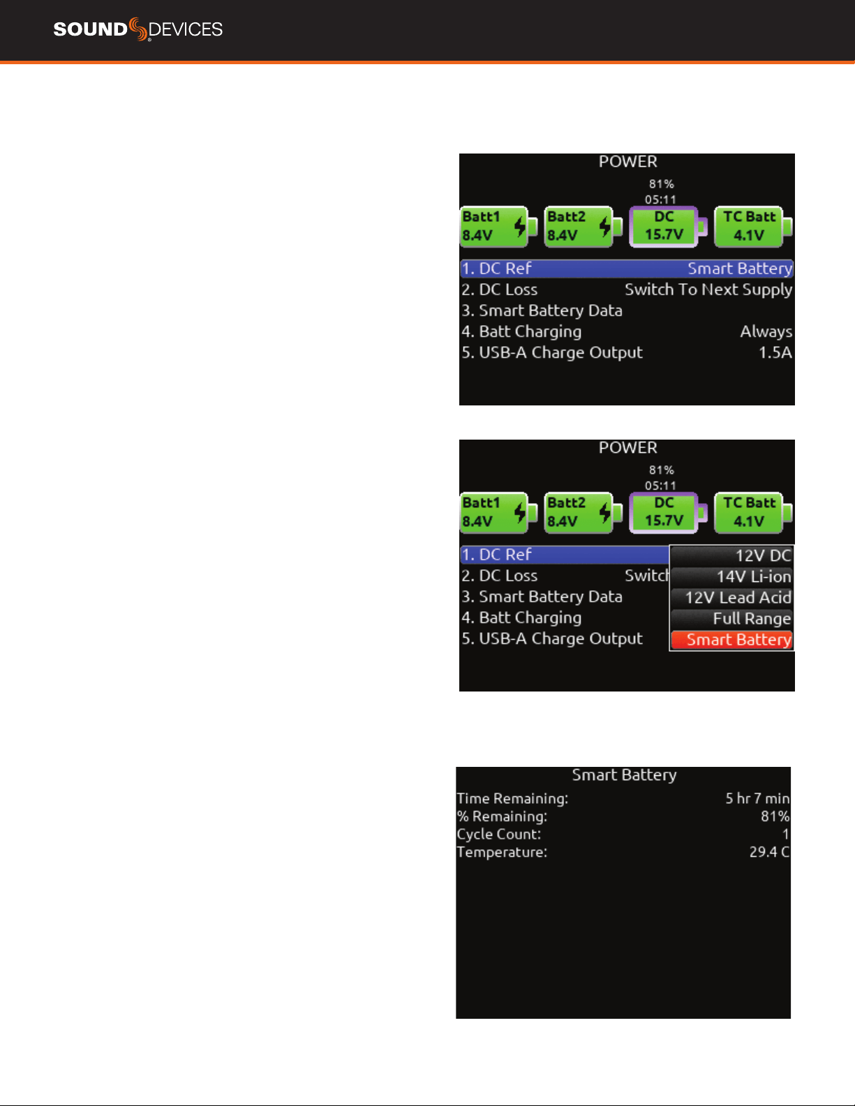
Power
Allows conguration of various power settings.
POWER SOURCE ICONS (Batt1, Batt2, DC, TC Batt) Indicates the
power condition of each power source. [Green = normal, yellow =
below normal, red = warning]
1. DC REF Allows proper power level indicator calibration based
upon the type of DC power source used. [12V DC*, 14 V Li-Ion, 12 V
Lead Acid, Full Range (10-18 V), Smart Battery]
2. DC LOSS Selects how the unit should operate when DC power is
lost. [Switch to Next Supply*, Turn Off]
3. SMART BATTERY DATA Displays Time Remaining, Percent Re-
maining, Cycle Count, and Temperature of Smart Battery.
Note: this menu is only displayed when a smart or data battery is
connected.
4. BATT CHARGING Selects battery charging mode when connected
to an external DC source. [Disabled, When Power On, When Power Off,
Always]
5. USB-A CHARGE PORT Allows charging of compatible external
USB devices such as Android tablets. Set to 500 mA or 1.5 A.
888 User Guide
15
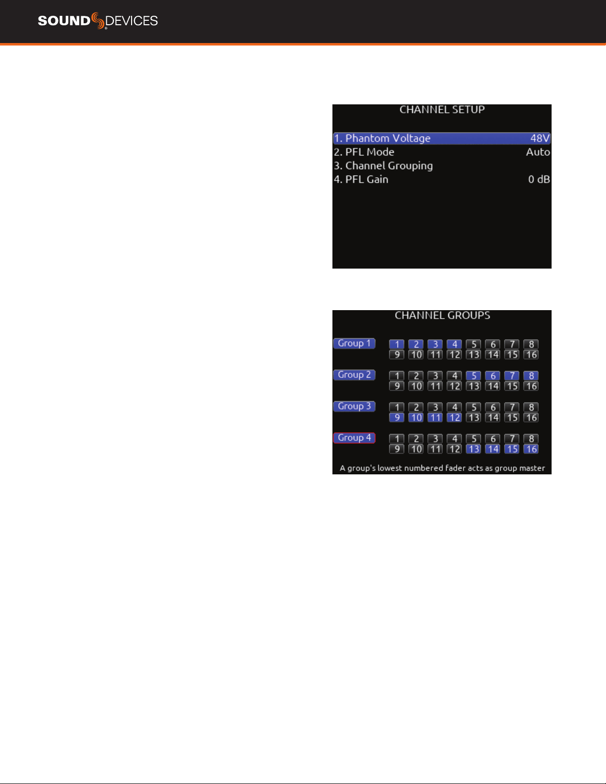
Channel Groups
CHANNEL GROUPS ENABLE/DISABLE
Provides global enable/disable for each of the four groups in the
channel grouping menu. Scroll to Group 1-4 using either knob, then
press the knob to enable or disable the group.
Channel Setup
1. PHANTOM VOLTAGE Selects phantom power voltage for all
inputs. [12 V, 48 V*]
2. PFL MODE Selects the source of the PFL feed. [Auto* Pre-fade,
Post-fade] Auto = pre-fade if channel is routed to ISO track pre-fade,
post-fade if channel is routed to the ISO track post-fade.
3. CHANNEL GROUPING Selects grouping of faders, record arming,
and mutes across channels. The lowest channel number in the group
controls the other channels grouped. Four channel groups are possi-
ble; channels grouped can only be assigned to one group.
a.
Group 1 [1-16]
b. Group 2 [1-16]
c. Group 3 [1-16]
d. Group 4 [1-16]
4. PFL GAIN A preset amount of gain that is applied to any chan-
nel(s) with active PFL.
888 User Guide
16
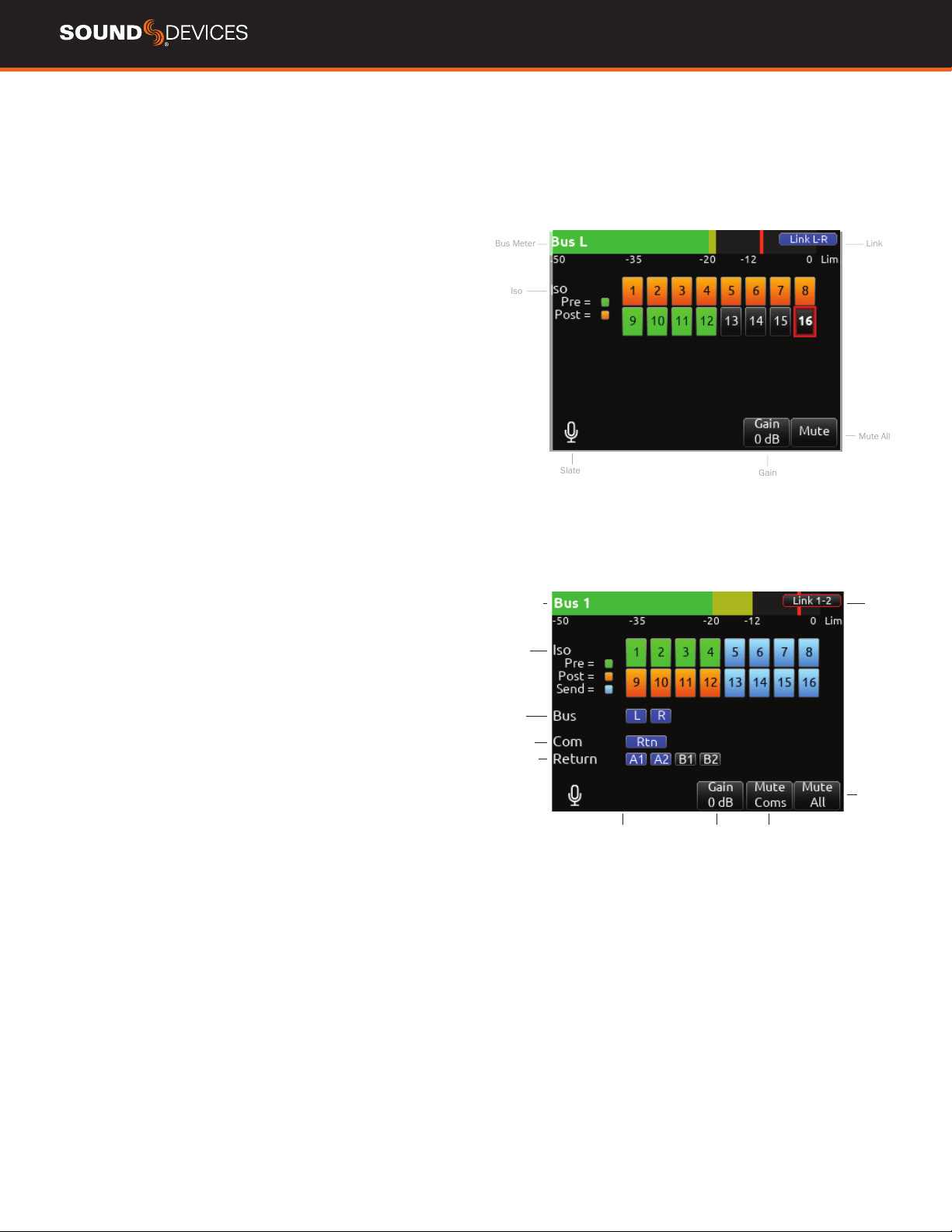
Buses
Selects routing for Buses L,R and 1-8.
1. BUS METER Audio level meter for the selected bus.
2. LINK *-* Selects linking for two odd-to-even numbered adjacent
buses. Links bus Gain, Mute, Coms, and Mute All functions.
3. ISO Any ISO channel contributes to Bus mix. [Green ll in text box
= Pre-fade, Orange ll in text box = Post-fade]
4. BUS Not available in L and R Bus Screens. Bus 1 and 2 allow rout-
ing of [Bus L or R]. Bus 3-8 allow routing of [Bus L, R, 1, or 2].
5. COM Rtn is not available on L,R buses. Bus 1-8 allow Com Rtn to
be routed.
6. RETURN Not available on L,R buses. Buses 1-8 allow routing of
[Return 1 or 2].
7. GAIN Use ** toggle to select and adjust selected bus gain in 1 dB
increments. [Off-16 dB]
8. MUTE COMS Selects muting of Com sends and returns.
9. MUTE ALL Indicates mute status of bus. Blue icon = muted. Tog-
gle Mute All On/Off with the “Fav” toggle.
Bus Meter Link
Iso
Slate
Gain
Mute All
Bus Meter
ISO
Bus
Com
Return
Link
Gain Mute
Coms
Mute All
888 User Guide
17
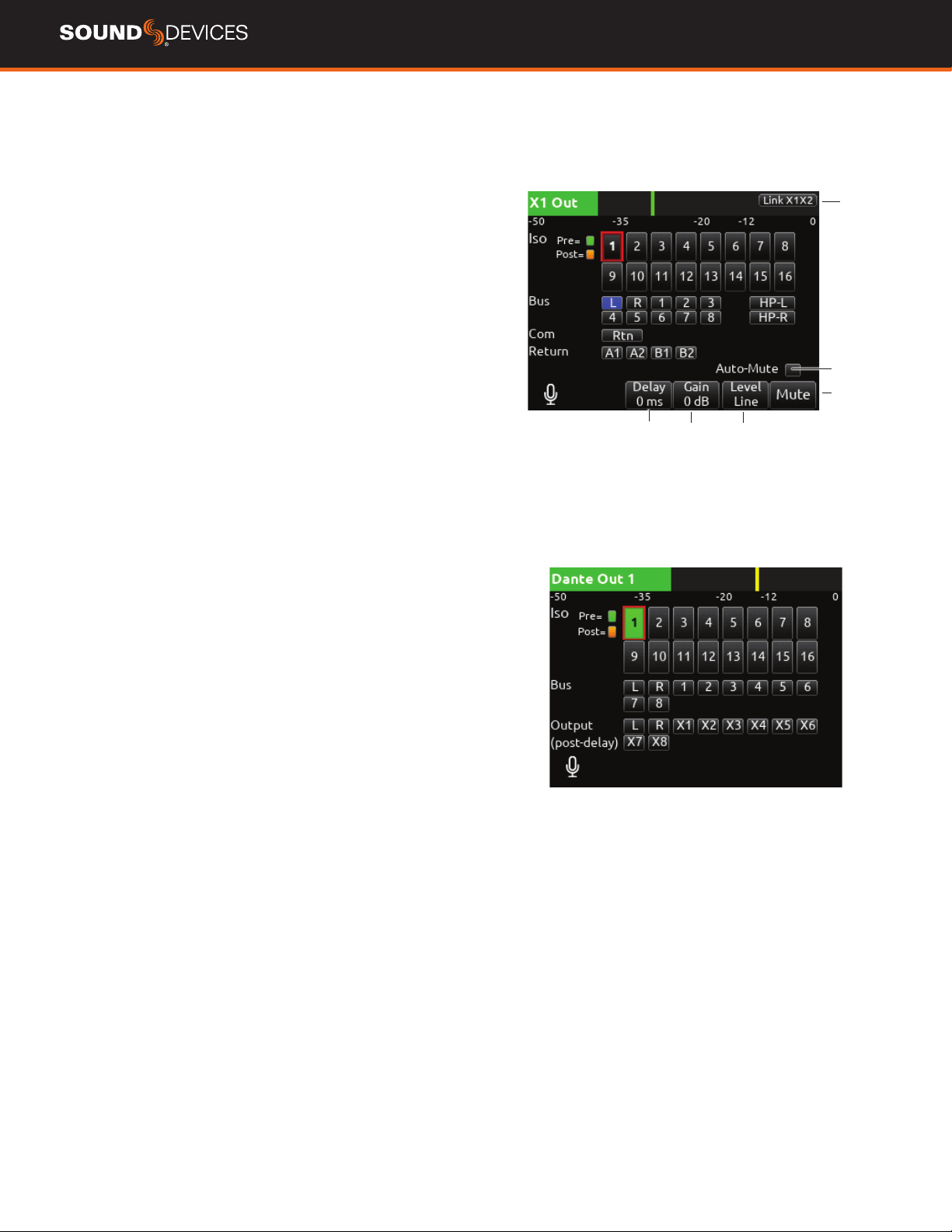
Outputs
1. LR, X1-X8 Output Routing
Selects routing for L,R and X1-X8 outputs. [L Out, R Out, X1, X2, X3,
X4, X5, X6, X7, and X8 Out]
Only a single source can be routed to an
Output. If multiple sources need to be routed, use a Bus.
A. ISO Selected source will contribute to the Output. (Green = Pre-
fade, orange = Post-fade [1-16])
B. BUS [L, R, 1-8, HP-L, HP-R]
C. COM Routes Com Return directly to the output.
D. RETURN Routes Return 1 or 2 directly to the output.
E. AUTO-MUTE Selects automatic muting of the output when in Stop
mode. Record and Playback modes are not muted.
F. DELAY The output delay is continuously-variable in milliseconds
from 0-500 ms.
G. GAIN Selects amount of attenuation applied to the output. Toggle
the ** to select. [0 dB to -50 dB and -inf]
H. LEVEL Selects output level type. [Line, -10, Mic]
J. MUTE Indicates mute status of output (Orange = muted) Toggle
Mute On/Off with the “Fav” toggle.
Link
Delay
Attn Type
Mute
Auto-Mute
4. Dante
Selects routing for Dante output.
A. ISO Any source selected will be routed to the selected Dante out-
put. (Green ll in text box = Pre-fade, Orange ll in text box = Post-fade
[1-16])
B. BUS [L,R, 1-8]
C. OUTPUT All sources are selected post-delay. [L,R, X1-X8]
888 User Guide
18
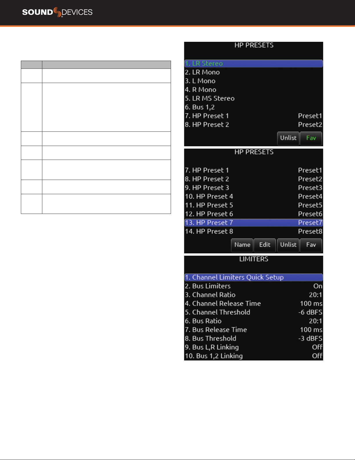
5. HP Presets
Selects the list of headphone presets available and allows for editing
and creation.
Function Description
Name Displays virtual keyboard and allows for naming of the
headphone preset.
Edit Allows selection of routed sources to both HP Left and HP
Right. Select HP LEFT or RIGHT and then select desired
source.
i. ISO- Any source selected will be routed to the selected
HP output. Green = Pre-fade, orange = Post-fade. [1-16]
ii. Bus- [L,R, 1-8]
iii. Com- [Rtn]
iv. Return- [A1, A2, B1, B2]
Mono Selects monophonic monitoring of selected HP-L/HP-R
sources.
MS Selects monophonic monitoring of selected HP-L/HP-R
sources.
Unlist De-selects a preset in the list preventing it from being
listed in the HP Preset menu (press HP knob on Home
Screen).
List Selects a preset in the list allowing it to be listed in the HP
Preset menu (press HP knob on Home Screen).
Fav Selects a favorite preset. The name turns green when
selected. The “Fav” switch recalls this HP preset when in
the Home Screen.
Limiters
CHANNEL LIMITERS QUICK SETUP Selects the channel limiters
on/off status globally. [All On*, All Off]
BUS LIMITERS Selects the bus limiters on/off status globally. [All
On*, All Off]
CHANNEL RATIO Selects the ratio of the limiter. [Inf:1, 10:1, 12:1,
14:1, 16:1, 18:1, 20:1*]
CHANNEL RELEASE TIME Selects the release time of the limiters
in 10 ms increments. 100 ms* [50-1000 ms]
CHANNEL THRESHOLD Selects the threshold at which the channel
limiters activate. -6 dBFS* [-2 to -12 dBFS]
BUS RATIO Selects the ratio of the limiter. [Inf:1, 10:1, 12:1, 14:1,
16:1, 18:1, 20:1*]
BUS RELEASE TIME Selects the release time of the limiters in 10
ms increments. 100 ms* [50-1000 ms]
BUS THRESHOLD Selects the threshold at which the bus limiters
activate. -3 dBFS* [-2 to -12 dBFS]
BUS LR LINKING Selects the linking of the L and R bus limiters.
[On, Off*]
BUS 1,2/3,4/5,6/7,8 LINKING- Selects the linking of bus pair
limiters. [On, Off*]
888 User Guide
19
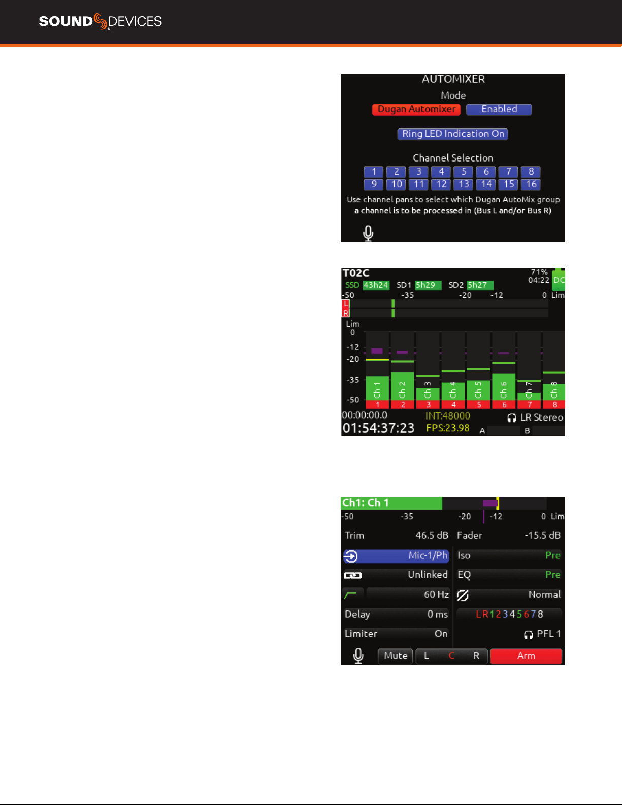
Automixer
Selects the Automixing mode and the channels included in the auto-
mixer group(s).
MODE Selects the Mode of Automix [MixAssist, Dugan Automixer]
and whether it is disabled* or enabled.
Tip:
Set a toggle shortcut or mapped controller button to enable/dis-
able the selected automixer mode to allow you to quickly compare the
effect of the automixer being on or off.
RING LED INDICATION Set to On to display automix meter levels on
the ring LEDs. Set to Off if you prefer to only see automix levels in the
LCD meter views only.
CHANNEL SELECTION Selects which of channels 1-16 are included
into the automix group(s).
Note: Automixer is only available with sample rates of 47952, 48000,
and 48048 Hz.
DUGAN AUTOMIXER MODE
Dugan gain display bars are overlaid on top of the channel signal
meters. The top 15 dB of the meter scale is shared between Dugan
gain display bars and audio signal metering. Dugan gain display bars
range from 0 dB (at the top, aligned with 0 dBFS, no attenuation) to
-15 dB (max attenuation). The -15 dB value is indicated by a purple
horizontal graticule mark to the left of a channel’s signal meter when
that channel is enabled for Dugan in Menu>Automixer.
There are two independent Dugan processing groups, Bus L and Bus
R. Channels 1-16 can be routed to Bus L, Bus R, both equally (Center),
or both unequally (L or R pan increments) by using a channel’s pan
control.
To show which Dugan group the channel is in, the Dugan gain display
bar is left-aligned for fully L, right-aligned for fully R and center-aligned
for any other pan value. When a channel is routed to both Dugan
groups (Bus L and R), the center-aligned gain display bar shows the
least attenuated value.
The Channel Screen shows the Dugan gain display bar overlaid within
the horizontal channel meter. The Dugan gain display scale and indi-
cation is the same as in the main meter screen.
The ring LEDs for ch 1-8 show Dugan gain for ch 1-8. The ring LEDs
begin to glow purple at 15 dB attenuation and increase in intensity at
0 dB attenuation.
888 User Guide
20
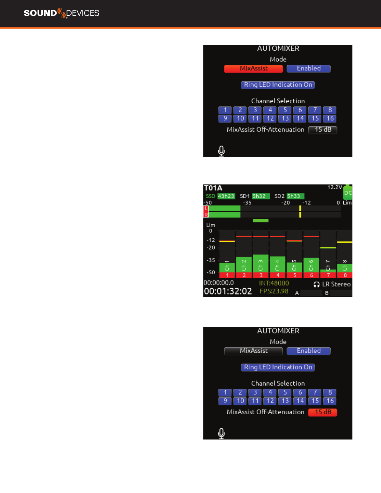
MIXASSIST MODE
MIXASSIST OFF-ATTENUATION Sets the amount of attenuation
applied to inactive input channels. Range: 6dB to 40dB. Default:
15dB
When a channel is active (not attenuated), it’s ring LED (channels 1-8
only) and LCD meter view channel indication illuminate green.
There are two independent MixAssist processing groups, Bus L and
Bus R. Channels 1-16 can be routed to Bus L, Bus R, both equally
(Center), or both unequally (L or R pan increments) by using a chan-
nel’s pan control.
888 User Guide
21
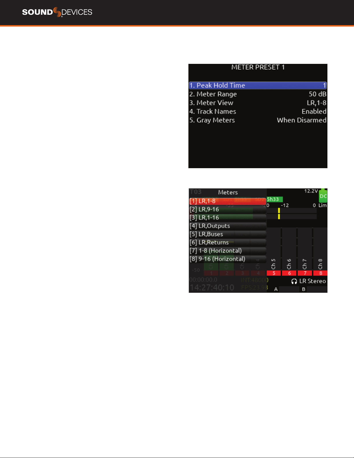
Meters
Selected Preset
METER PRESETS 1-8 (Horizontal) 9-16 (Horizontal).
A. PEAK HOLD TIME Selects the peak hold time for the meter
preset. [Off, 1*-5 s, Innity]
B. METER RANGE Selects the range of the meters from bottom to
top of scale. [50 dB*, 40 dB, 20 dB]
C. METER VIEW Selects the meters to be viewed in the current
preset. [LR,1-8, LR,9-16, LR,1-16, LR,1-12, 1-8 (Horizontal), 9-16
(Horizontal), LR,1-8 (Horizontal), LR, 9-16 (Horizontal), LR,Outputs,
LR,Buses, LR,Returns, LR Outputs (Horizontal),LR Buses (Horizontal)]
D. TRACK NAMES Selects display of track name in meters.
[Enabled*, Disabled]
E. GRAY METERS Selects gray meter when record disarmed. [When
disarmed*,Off]
Meter View Menu Shortcuts
WHEN IN LR, OUTPUTS AND LR, BUSES METER VIEWS Turn
Select knob to scroll to an output or bus. Pressing select acts as a
shortcut to that outputs or bus routing screen.
888 User Guide
22
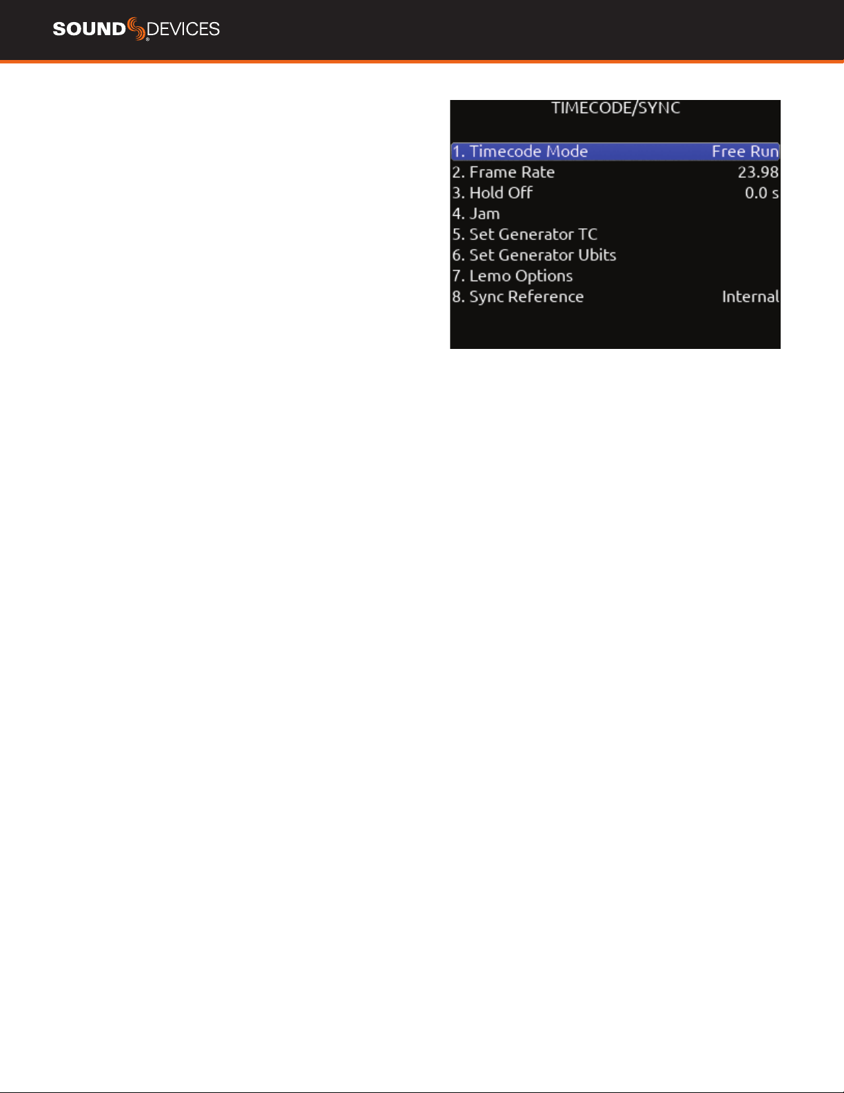
Timecode
TIMECODE MODE Selects the timecode mode of operation. [Off,
Record Run, Free Run*, Free Run Auto Mute, Free Run Jam Once, 24
Hour Run (ToD), 24 Hour Run Auto Mute, Ext TC, Ext TC - Auto Record,
Ext TC Continuous, Ext TC Cont. - Auto Record]
FRAME RATE Selects the current frame rate. [23.98*, 24, 25,
29.97 ND, 29.97 DF, 30 ND, 30 DF]
HOLD OFF Selects the amount of time incoming Timecode needs to
be valid prior to entering record when in auto-record mode. [0.0*-8.0
seconds in steps of 0.1 sec.]
JAM Indicates the Received TC, Generator TC and the calculated
difference between the two. Received and Generator UBits are shown.
Jamming to external TC and UBits is supported.
Jam TC- Toggle Rtn/Fav switch to jam to external TC.
SET GENERATOR TC Provides the ability to start rolling internal TC
from a manually entered value in the format of HH:MM:SS:ff.
SET GENERATOR UBITS Provides UBits manual and automatic
entry. [U=User entered UU:UU:UU:UU*, mm:dd:yy:UU, dd:mm:yy:UU,
Use External] Use Rtn/Fav toggle to exit.
LEMO OPTIONS Selects pin-2 and pin-5 options for TC Lemo
connector.
a. Pin-2 - [TC In*, WCK In, WCK Out]
b. Pin-5 - [TC Out, WCK Out]
SYNC REFERENCE Selects current sync reference for all transport
modes (record, stop and play). [Internal*, Word Clock, LTC In, AES 1,2]
Ring LEDs ash yellow while locking to the selected sync reference.
Once locked, the LEDs will stop ashing. Should the LEDs ash
indenitely, the selected sync reference has not been detected.
Locking can take up to 30 seconds.
The 888 will hold timecode for four hours after shutdown.
888 User Guide
23
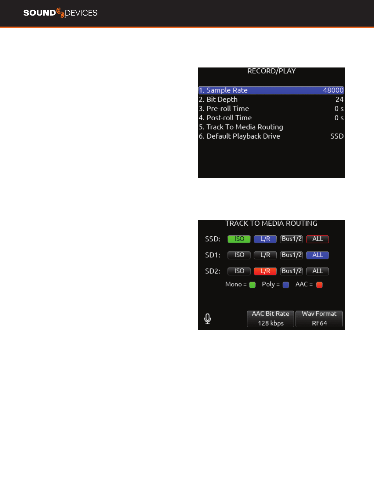
Record/Play
SAMPLE RATE Selects the current sample rate. [44100, 47952,
48000*, 48048, 96000, 192000]
BIT DEPTH Selects the current bit depth. [16, 24*]
PRE-ROLL TIME Selects the amount of Pre-roll recording. Adjustable
in 1 second increments. *0 s [0-10 s]
POST-ROLL TIME Selects the amount of Post-roll recording. Ad-
justable in 1 second increments. [0-10 s] If a recording is stopped
prematurely, press record within the post-roll time. The machine will
continue to record into the original le. Useful for when directors call
‘cut’ prematurely. During the post-roll period, the transport joystick
ring LED shows orange. Pressing stop again during the post-roll period
cancels the post-roll and stops recording.
TRACK TO MEDIA MENU Selects the sources for each recording
media as well as the WAV le type recorded. Tracks may be routed
to media to be recorded as Mono or Poly les. (Green ll in text box=
Mono le, Blue ll in text box= Poly le)
Tracks L/R and Bus1/2 can also be recorded as AAC audio les.
(Orange ll in text box). AAC les are ideal for transcription.
Select the AAC Bit Rate using the */** toggle switches. [32, 64, 128,
192, 256 kbps]
A. SSD- [ISO, L/R, Bus1/2, ALL]
B. SD1- [ISO, L/R, Bus1/2, ALL]
C. SD2- [ISO, L/R, Bus1/2, ALL]
* Up to 20 track recording supported with sampling rates 44.1- 96
kHz. Up to 18 track recording at 192 kHz.
**Monophonic le recording up to 48.048 kHz.
*** AAC le format when recording at 48 kHz.
DEFAULT PLAYBACK DRIVE Selects the drive for playback. [SSD,
SD1, SD2]
PLAYBACK TAKE FROM TAKE LIST Enter the take list and select
a take with either knob. Pressing play will playback the selected take.
ARMING/DISARMING DURING RECORDING All channels can be
armed/disarmed while recording. This creates a seamless split to a
new le or les. The split takes will be sufxed with an incrementing
alphabetic character. I.e. A, B, C...
AUTO-SPLIT Takes that are auto-split due to the 4 GB limit of BWF
format are also sufxed using the same A, B, C...incrementation.
RECORD SPLIT Takes that are split when pressing record during
recording increment the le’s take number.
888 User Guide
24
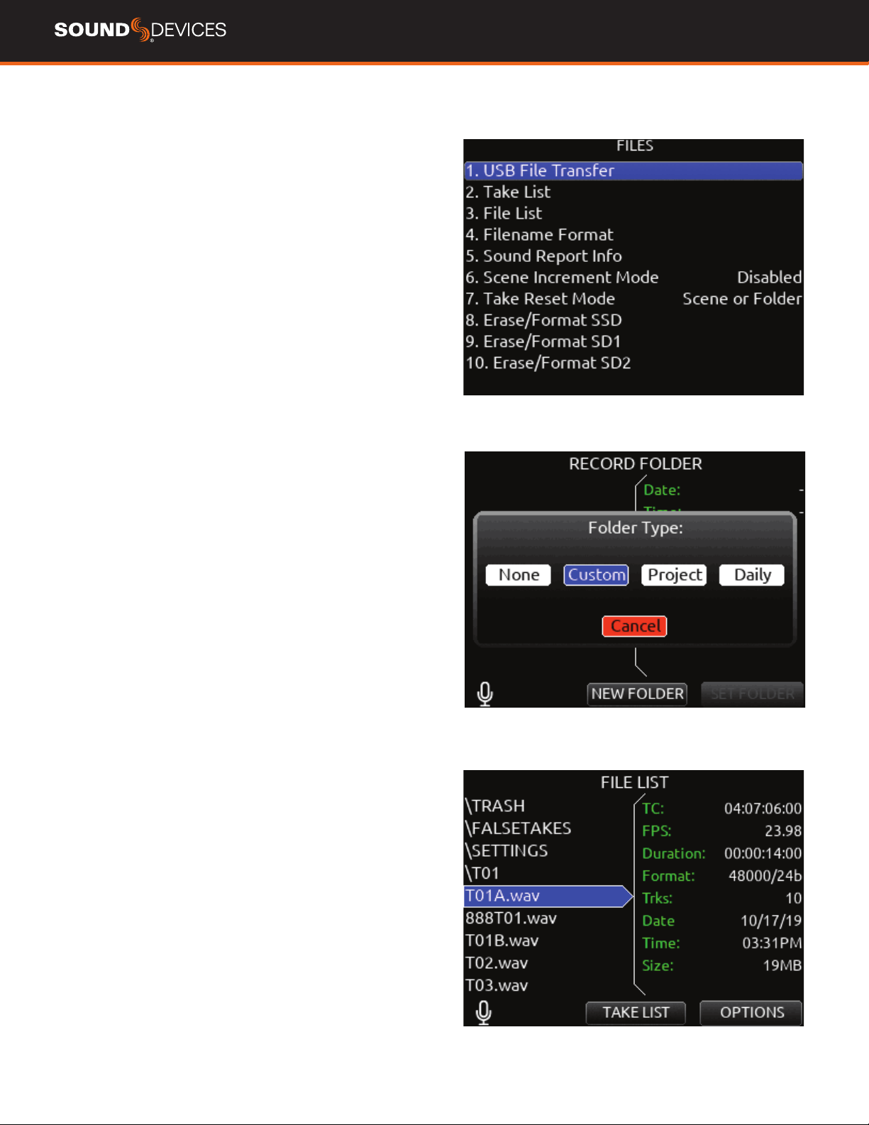
Files
USB FILE TRANSFER Enters USB le transfer mode. Files may be
transferred between a Mac or PC and the 888 via USB-C port.
When in USB le transfer mode, playback, record and controller func-
tions are suspended.
TAKE LIST Enters the Take List. The Take List shows a running list of
recorded takes in chronological order with most recent at the top. Var-
ious details of each take are indicated on the right side of the display:
TC (timecode), Duration, Media, Folder, Scene, Take, Date, and Notes.
From this list, takes may be selected for metadata editing by using the
Rtn/Fav toggle to access the Take Edit Menu.
RECORD FOLDER To select or create a Record folder, go to the Take
List > Next Take Edit Screen and select REC FOLDER using the * or
** Toggle switch. A Record Folder stores recorded takes (audio les)
and sound reports. Record Folders can be created and nested up to
three levels deep. A new or existing Record Folder can be selected for
recording into.
There are 4 types of Record Folder:
1. None- Files are stored at drive root. When ‘None’ is selected, the
Date is embedded as Tape metadata.
2. Custom- Files are stored in a custom-named folder; the Custom
folder name is embedded as Tape metadata in the recorded audio
les.
3. Project- Files are stored in a folder with a name determined by the
Project name entered in the Take List > Next take Edit Screen. The
Project folder name is embedded as Tape metadata.
4. Daily: les are stored in a folder whose name is in the format
yyYmmMdd. When a Daily folder is selected, the Date is embedded as
Tape metadata.
When the monophonic wav le format is selected (in the Record/Play
> Track to Media Routing menu), all mono les created for a take will
follow the naming of the take and be placed in a take folder within the
selected record folder.
888 User Guide
25
TAKE EDIT MENU
1. Notes: Edit notes for the selected take. Maximum 200 characters
including Sticky Notes.
2. Sticky Notes (next take only): edit sticky notes that are automatical-
ly prepended to subsequent takes. Maximum 50 characters.
3. Scene: Edit scene name. Maximum 50 characters.
4. Take: edit Take Number.
5. Circle (current or previous takes only): circle a take. Prepends “@”
symbol to take name.
6. Project Edit Project name. Maximum 20 characters. This will be-
come the record folder name if Project is selected as the Folder Type.
7. Delete (current or previous takes only): moves a selected take to a
drive’s Trash folder.
8. Track Names: edit track names. Maximum 20 characters.
FILE LIST Enters the File List. The File List displays the 888’s internal
SSD and SD cards and their contents. Various details of each drive,
folder, and WAV le are indicated on the right side of the display: TC,
FPS:, duration, format, tracks, date, time, size.
FILENAME FORMAT Selectable naming conventions for recorded
les. Selectable between Scene (Slate) T,+,- Take, or Project ;,%, =
Scene (Slate) T,+,- Take.
SOUND REPORT INFO Selects the various content for each eld of
a sound report.
SCENE INCREMENT MODE Denes whether a scene name shall be
incremented numerically or alphabetically when the scene increment
shortcut is used.
TAKE RESET MODE Selects when a Take Number shall reset to 1.
Options are: Never, Scene Change, Folder Change, Scene or Folder
Change.
ERASE/FORMAT SSD Select to erase/format the internal SSD.
ERASE/FORMAT SD1 Select to erase/format SD1.
ERASE/FORMAT SD2 Select to erase/format SD2.
All created folders will be placed on the root of the media. All mono
les created for a take will follow the naming convention of the take
and be placed in the take folder.
FOLDER NAME/TAPE METADATA
When a Project folder is selected, the Project is embedded as Tape
metadata.
When a Custom folder is selected, the Custom folder name is embed-
ded as Tape metadata.
When a Date or “None” folder is selected, the Date is embedded as
Tape metadata.
888 User Guide
26
File List
Allows navigation and management of les and folders on the SSD,
SD1 and SD2 drives.
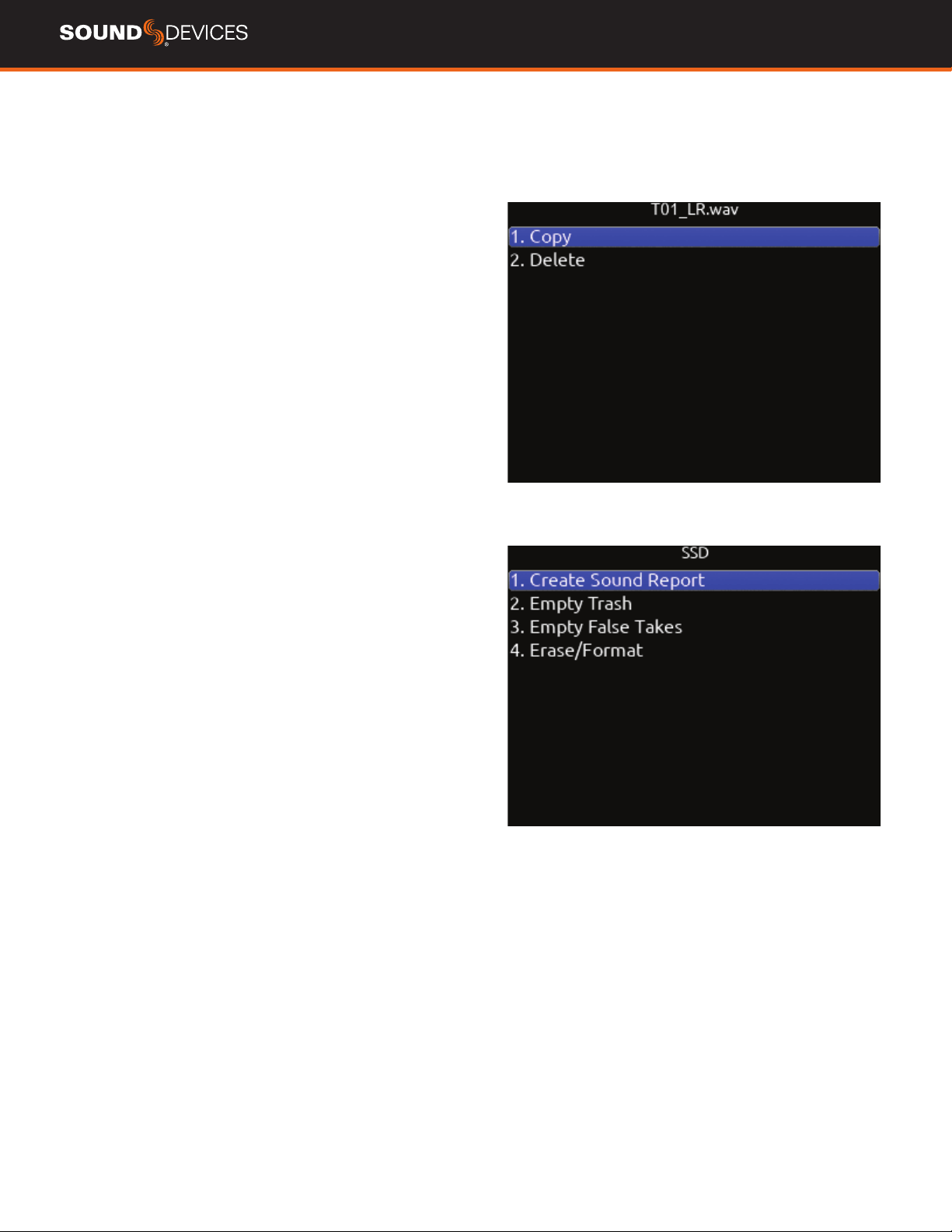
File List Options
COPY FOLDER/FILE Provides support for copying Folders and
Files between drives from the File List’s Options Menu.
DELETE FOLDER/FILE Delete Folders and Files from the File List’s
Options Menu.
CREATE SOUND REPORT Creates a CSV sound report for the
selected folder’s takes.
EMPTY TRASH Empties the trash folder.
EMPTY FALSE TAKES Empties the false takes folder.
ERASE/FORMAT Formats the selected drive.
888 User Guide
27
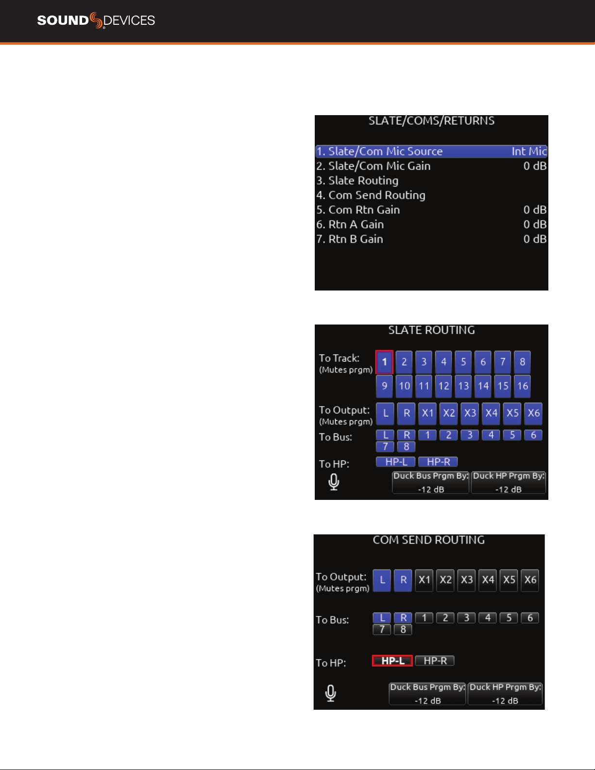
Slate/Coms/Returns
SLATE/COM MIC SOURCE Selects the slate and com mic source.
[Off, Int Mic*, Ext Mic, Ext 12 V Mic]
SLATE/COM MIC GAIN Selects the gain for the slate/com mic. [0-
20 dB in 1 dB steps for the internal mic, 0-60 dB in 1 dB steps for the
external mic].
SLATE ROUTING Selects the destination(s) for the slate mic.
a. Track- [1-16]
b. Output- [L,R, X1-X6]
c. Bus- [L,R, 1-8]
d. HP- [HP-L, HP-R]
e. Duck Bus Program (Prgm) By: [0- -40 dB, -inf]
f. Duck HP Program (Prgm) By: [0- -40 dB, -inf]
COM SEND ROUTING Selects the destination(s) for Com Send.
a. Output- [L,R, X1-X6]
b. Bus- [L,R, 1-8]
c. HP- [HP-L, HP-R]
d. Duck Bus Prgrm By: [0- -40 dB, -inf]
e. Duck HP Prgrm By: [0- -40 dB, -inf]
COM RTN GAIN Selects the gain for Com Rtn in 1 dB increments.
[0-30 dB]
RTN A GAIN Selects the gain for Rtn A in 1 dB increments. [0-30 dB]
RTN B GAIN Selects the gain for Rtn B in 1 dB increments. [0-30 dB]
DUCK BUS PROGRAM BY Ducks all audio sent to the bus by a user
dened amount.
DUCK HP PROGRAM BY Ducks all audio sent to headphones by a
user dened amount.
When sending coms or slate signal to outputs the program routed to
that output is replaced by the com or slate signal.
888 User Guide
28
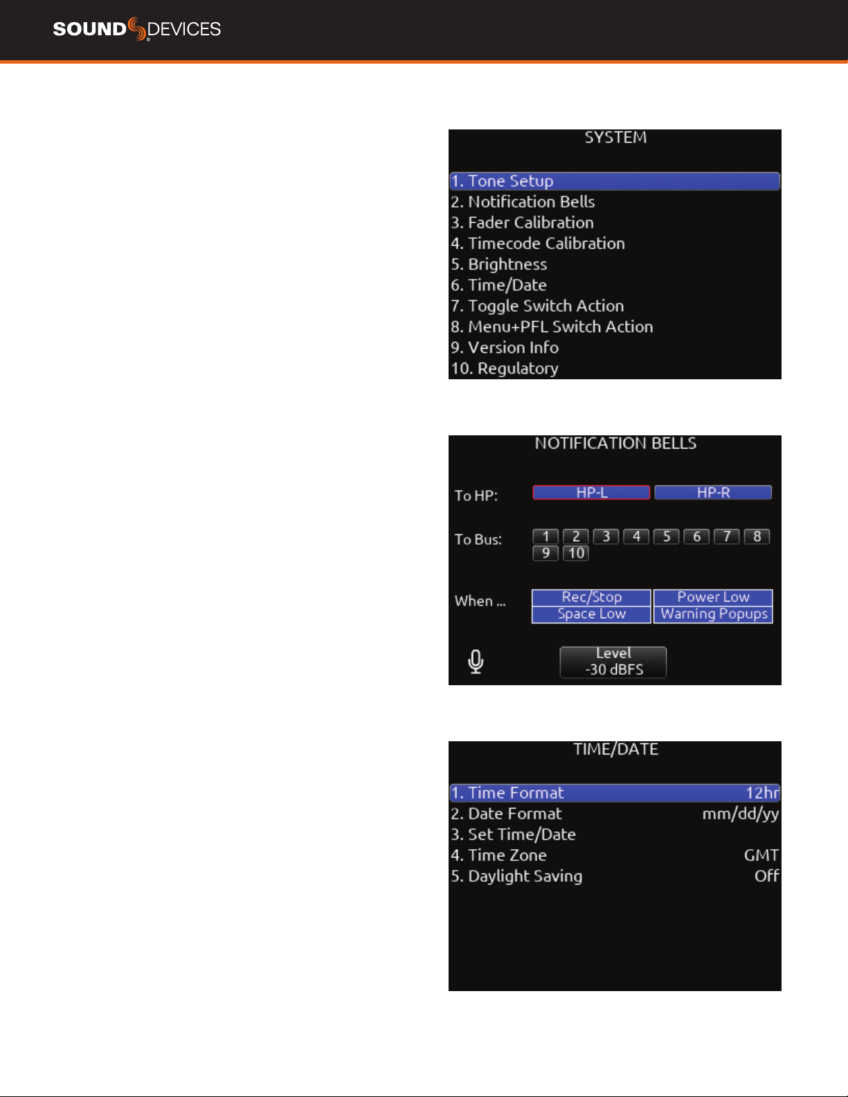
System
TONE SETUP Selects the level, frequency, and routing of the internal
tone generator.
a. Level- Selects the level of the tone generator from -20 - 0 dBFS in 1
dB increments. [-20 - 0 dBFS]
b. Frequency- Selects the frequency of the tone from 100 to 10 kHz in
10 Hz steps. [100-10 kHz]
c. Track- [1-16]
d. Output- [L,R, X1-X6]
e. Bus- [L,R, 1-8] (Use toggle Switch Action menu to select tone as
Continuous or L-ident.)
NOTIFICATION BELLS Selects settings for the notication bells.
a. To HP- Routes notication bell tones to the headphones. [HP-L,
HP-R]
b. To Bus- Routes notication bell tones to the buses. [L,R, 1-8]
c. When…- Selects when the notication bell tones are used. [Rec/
Stop, Space Low, Power Low, Warning Popup]
d. Level- Selects the level at which the notication bell tones will be
played in 1 dB increments. [Muted, -60 to -12 dBFS]
FADER CALIBRATION Selects the option to manually calibrate all
faders.
TIMECODE CALIBRATION Tunes the 888 system clock to an
external LTC signal.
BRIGHTNESS
Selects the brightness of the LED display and front
panel LEDs.
a. LED Brightness- Selects the front panel LED brightness in 10%
steps. [10%-100%]
b. Selects the front panel LCD display brightness in 10% steps. [10%-
100%]
TIME/DATE Selects the current date and time.
a. Time Format- [12*, 24 hr]
b. Date Format- [mm/dd/yy*, dd/mm/yy, yy/mm/dd]
c. Set Time/Date- Selects the current date and time.
d. Time Zone- [-12 to +13 hours GMT]
e. Daylight Saving- [On, Off*]
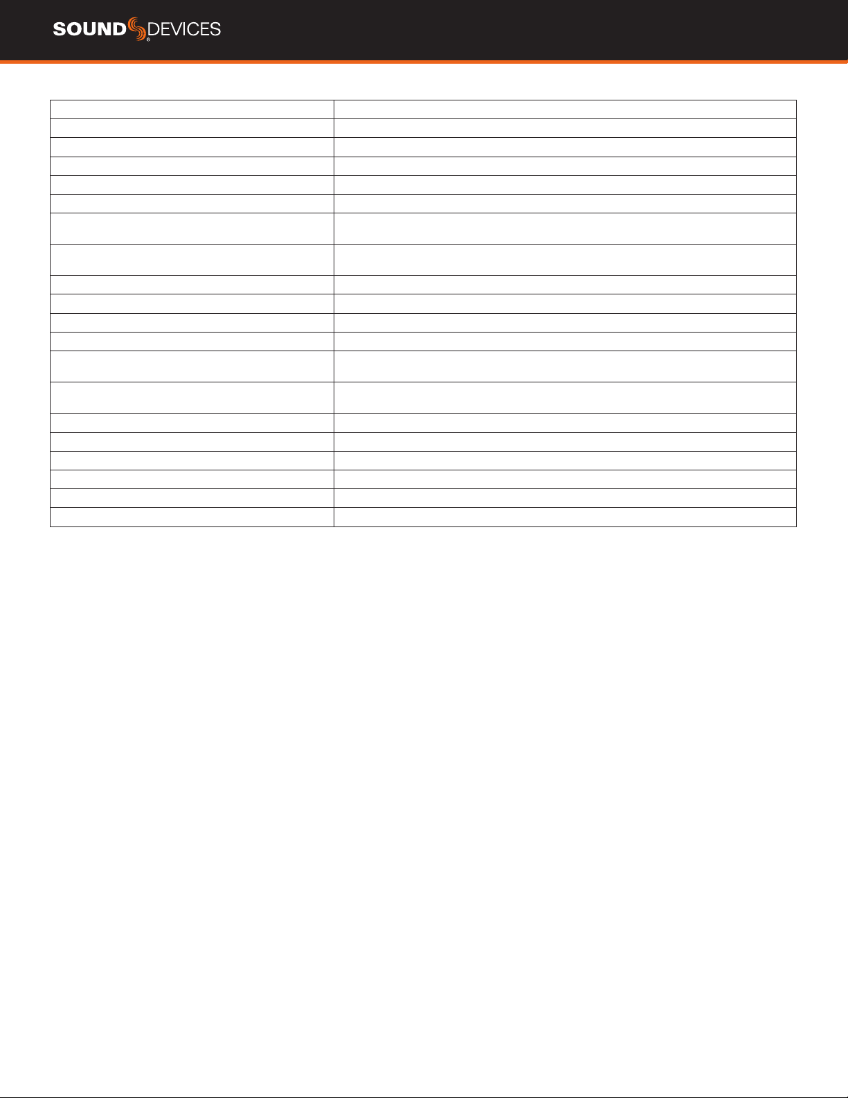
TOGGLE SWITCH ACTION
Chooses what function is assigned to
the toggle switches.
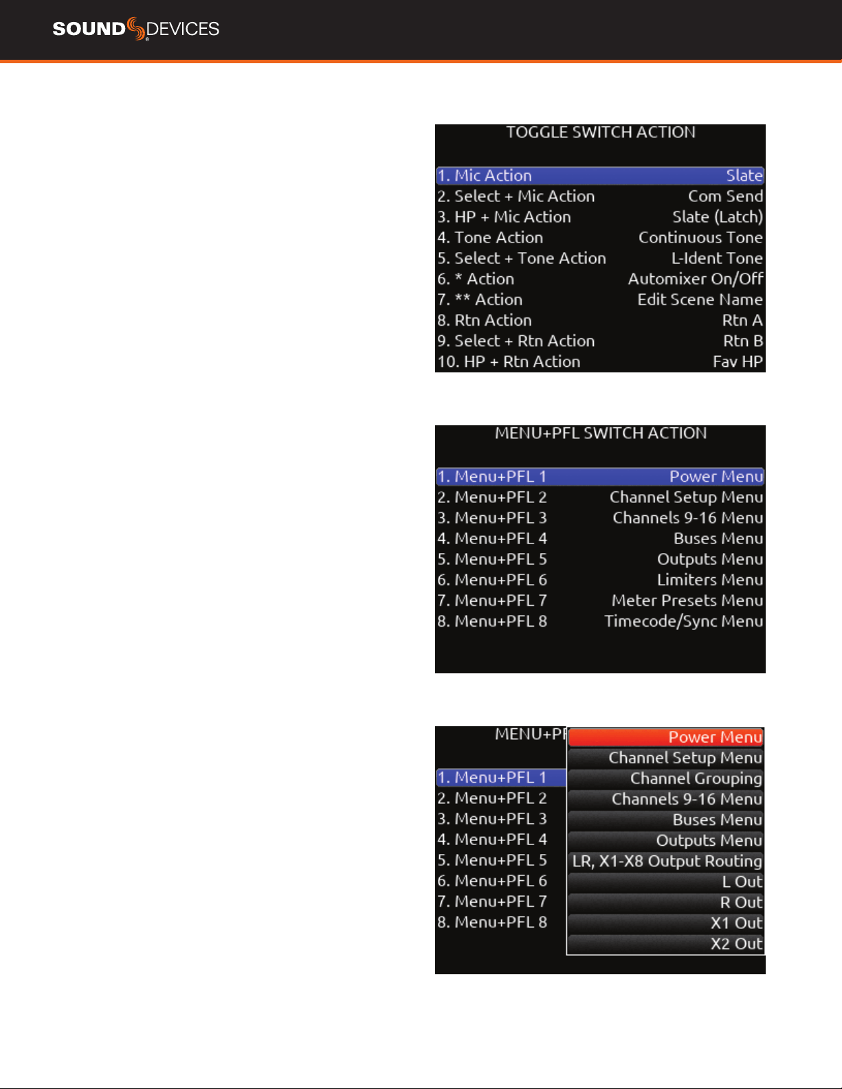
MENU + PFL SWITCH ACTION Chooses what menu is assigned to
a Menu + PFL Switch action.
VERSION INFO Indicates current rmware version.
REGULATORY Displays relevant compliance information.
FIRMWARE UPDATE Selects any PRG update les present on any
media.
888 User Guide
29
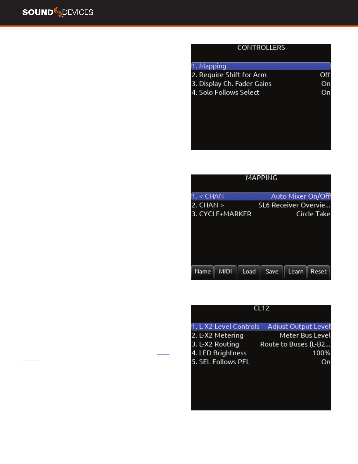
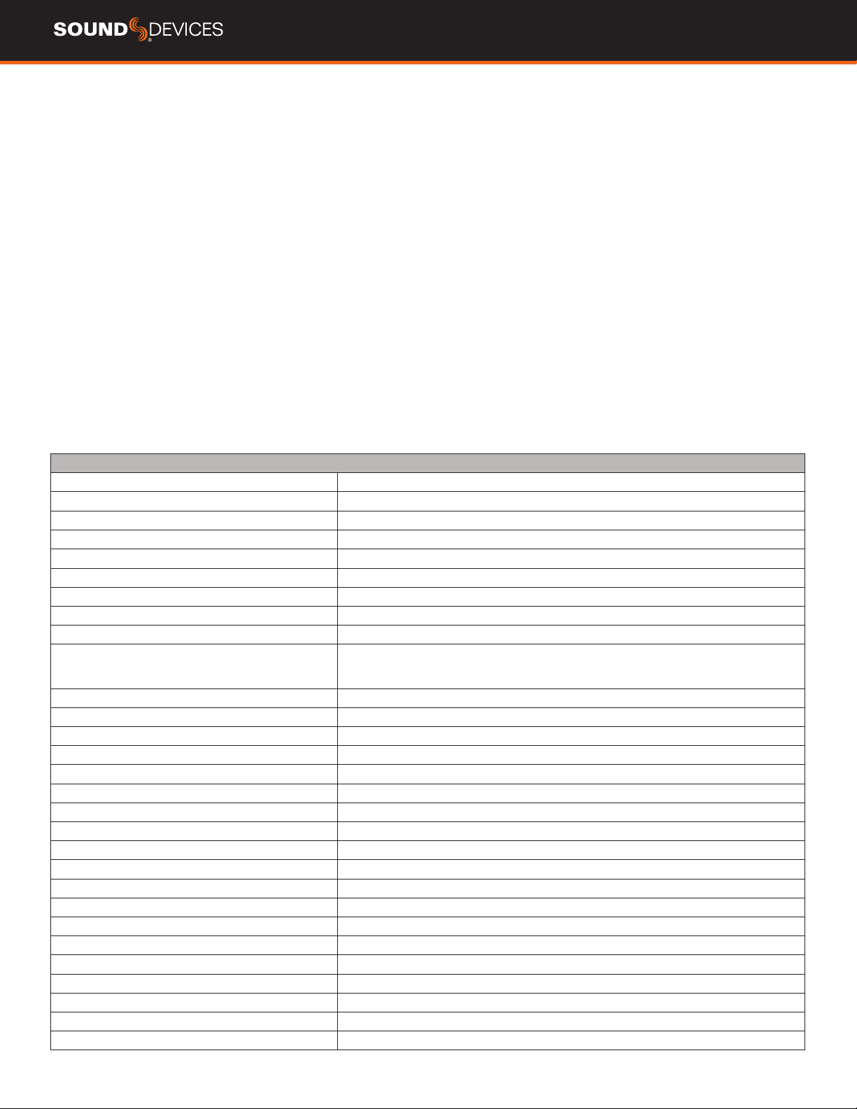
Controllers
The 888 can by controlled from the Sound Devices CL-12 linear fader
controller or supported third-party external controllers that conform to
the MCU protocol.
Controllers connect via the 888’s USB-A port either directly or via a
USB hub.
MAPPING Selects Mapping menu.
a. Name- Allows for custom naming of controller button.
b. MIDI- Toggles between the button name and MIDI code of the
selected button function.
c. Load- Loads a saved button mapping preset.
d. Save- Saves a button mapping preset to any/all media. Toggle “Fav”
after media selection to save.
e. Learn- Selects learn function. To use, toggle Learn and press the
desired button to be learned on the controller. Once the button has
been learned, press the HP knob to scroll through the possible list of
available functions (shown below) that can be assigned and select
the desired function.
f. Reset- Deletes the currently selected button mapping in the Map-
ping menu.
REQUIRE SHIFT FOR ARM When selected, “Shift” on external
control surface must be pressed simultaneously with “Rec” to arm
tracks. [Off*, On]
Applies to supported 3rd party controllers only.
DISPLAY CH. FADER GAINS Selects whether the fader gains are
displayed in the controller’s display. [Off, On*]
Solo Follows Select- Selects whether solo (PFL) mode is engaged on a
channel when pressing “Select” from the controller. [Off, On*]
Applies to supported 3rd party controllers only.
SOLO FOLLOWS SELECT Selects whether solo (PFL) mode is
engaged on a channel when pressing “Select” from the controller [Off,
On*]
Applies to supported 3rd party controllers only.
CL-12 Selects CL-12 menu.
1. L-X2 Level Controls: sets whether the L-X2 pots control bus level or
output level or whether they are disabled altogether.
2. L-X2 Metering: sets whether the L-X2 meters display bus or output
levels.
3. L-X2 Routing: sets whether L-X2 routing is to buses L-X2 or outputs
L-X2.
4. LED Brightness: sets CL-12 LED brightness.
5. SEL Follows PFL: selects whether a channel is automatically select-
ed when its PFL is engaged.
CL-12 CONTROLLER
12 channel linear fader controller with control over fader gain, PFL,
Arm, EQ, buses, outputs, coms, transport, metadata, and more. For
detailed setup and operational information, please refer to the
CL-12
User Guide.
Tips:
When CL-12 is connected to the 888, trim gains are controlled from
888.
Slate mic can be toggled on/off by pressing both COM 1 and COM 2
simultaneously.
When adjusting EQ from the CL-12, the EQ values are displayed at the
bottom of the meter view.
888 User Guide
30
Function Action
Auto Mixer On/Off Toggles the Auto Mixer on/off.
Bus Mode Bus Masters.
Channel Groups Edit Create/Edit channel groups.
Channel Sends on Faders Shortcut to put Bus sends on linear faders/toggle on/off.
Channel Source Edit Patch input to channel.
Circle Take Circle take.
Com Activates Com Send.
Com Rtn Activates Com Rtn.
Dante Out Edit Shortcut to Dante Output Routing screen.
EQ Mode Spills EQ parameters over scribble strips, Fader Bank right to view last parameter.
Push and hold V-Pot 1 to toggle EQ on/off, push each band’s amplitude V-Pot to toggle
on/off each band, push each band’s Q V-Pot to toggle eq type Shelf/Peak.
False Take Activates False Take function.
Fat Ch. Mode Spills fat channel parameters across scribble strips.
Fav HP Preset Recalls Fav HP Preset from Main Menu>Outputs>HP Presets.
Fav Toggle Emulates Fav toggle on 888.
Home Activates Home screen and Trim knobs mode.
HP Presets Menu Shortcut to Main Menu>Outputs>HP Presets.
Jog is HP Switches Jog wheel to emulate HP knob on the 888.
Jog is Select Switches Jog wheel to emulate Select knob on the 888.
Jog Wheel Press Acts as “Select” while using jog wheel.
L-ident Indenties left channel output by varying amplitude vs. right channel with constant amplitude.
LR Returns Meter Activates the returns meter view.
Menu Emulates the Menu button on the 888.
Meters Emulates the Meter button on the 888.
Mic Toggle Emulates the Mic toggle on the 888.
Mix Pan Mode Activates all V-Pots to Pan mode on every channel. Push to center pan.
Mix Trim Mode Activates all V-Pots to Trim mode on every channel. Push to enter pan mode.
Nav Down Moves the highlighted selection up one in matrix screens, emulates HP knob down in Home screen.
Nav Left Navigates back to previous screen.
Nav Right Selects the currently highlighted selection.
SUPPORTED THIRD-PARTY CONTROLLERS
The 888 supports some third-party external controllers that conform
to the MCU protocol. Two controllers may be connected simultaneous-
ly for extended control. The CL-12 Linear Fader Controller cannot be
used with another control surface.
ICON PLATFORM M+ AND D2 DISPLAY Eight channel fader bank
with control over gain, bus, sends, coms, trim and pan. Dedicated
Select, Mute, Solo and Arm buttons for each channel. Bank switch to
access 888 channels 1-16 in blocks of 8 banks.
ICON PLATFORM X+ Eight channel expansion fader bank with
single assignable knob and Select, Mute, Solo and Arm buttons.
ICON PLATFORM B+ Assignable illuminated 50 pad button surface.
BEHRINGER X-TOUCH Eight channel trim and fader panel with
master volume and additional mappable buttons. Bank switch to
access 888 channels 1-16 in blocks of 8 banks.
MACKIE MCU PRO Eight channel trim and fader panel with master
volume and additional mappable buttons. Bank switch to access 888
channels 1-16 in blocks of 8 banks.
In addition, any MCU controller may be custom-mapped to perform
any of the following actions on the 888:
888 User Guide
31
Scene Increment Brings up the Scene Increment Dialog box for incrementing Scene Name
according to the setting in Files>Scene Increment Mode.
Scene Name Brings up the Scene Name Edit virtual keyboard screen for editing the current
take’s scene during record and the next take’s scene during stop.
Edit Scene Name Edits current scene name.
Select Selects the currently highlighted selection in menus and matrix screens.
Slate Toggles Slate on/off.
Take List Brings up the Take List.
Take Notes Edit Brings up the Notes Edit virtual keyboard screen for editing the current
take’s notes during record and the next take’s notes during stop.
Take Number Edit Brings up the Take number edit screen for editing the current take
number during record and the next take number during stop.
Timecode Jam Brings up the Timecode Jam screen.
Toggle Jog is Select Toggles between Select and HP knob press on the 888.
Tone Toggles tone on/off.
Tone Toggle Emulates Tone toggle on the 888.
* Toggle Emulates * toggle on the 888.
** Toggle Emulates ** toggle on the 888.
Nav Up Moves the highlighted selection down one in matrix screens, emulates HP knob up In Home screen.
Out Mode Selects the output masters mode.
Play Remain Time Selects the remaining time in the LED timecode display.
Rtn A Selects Rtn A toggle on/off.
Rtn B Selects Rtn B toggle on/off.
Rtn Toggle Emulates the Rtn toggle on the 888.
888 User Guide
32
Toggle Switch Action
SELECT + MIC, HP + MIC, MIC Selects Slate, Slate (Latch), Slate
(Moment), Com Send, Com Send (Latch), Com Send (Moment), or No
Action.
SELECT + TONE, TONE Selects Continuous Tone, L-ident Tone or No
Action.
*/** [Jam Menu, Circle, Slate, Slate (Latch), Slate (Moment), Com
Send, Com Send Latch, Com Send Moment, Rtn A, Rtn B, Com Rtn,
Automixer On/Off, Scene Name, Take Number, Take Notes, Edit Scene
Name, No Action]
SELECT + RTN, HP + RTN, RTN [Rtn A, Rtn B, Com Rtn, Fav HP, No
Action]
SELECT + FAV, FAV + HP, FAV [Rtn A, Rtn B, Com Rtn, Fav HP, No
Action]
Menu + PFL Switch Action
MENU+PFL SWITCH [1-8] [Power Menu. Channel Setup Menu,
Channel Groupings, Channels 9-16 Menu
, Buses Menu, Outputs
Menu, (LR, X1-X8 Output Routing), L Out, R Out, X1 Out, X2 Out, X3
Out, X4 Out, X5 Out, X6 Out, X7 Out, X8 Out, Dante Output Routing,
Dante Out 1-16, HP Presets, Limiters Menu, Meter Presets Menu,
Meter Preset 1-8, Timecode/Sync Menu, Jam Timecode, Set Genera-
tor TC, Set Generator Ubits, Lemo Options, Record/Play Menu, Track
To Media, Files Menu, File List, Take List, File Name Format, Sound
Report Info, Slate/Coms/Returns Menu, Slate Routing, Com Send
Routing, System Menu, Tone Setup, Notication Bells, Brightness,
Time/Date Menu, Toggle Switch Action, Menu+PFL Switch Actions,
Controllers Menu, Automixer On/Off, Take Number, Take Notes, Scene
Name]
888 User Guide
33
Front Panel Shortcuts
The Menu + PFL Shortcuts are set by default. They can be
customized by going to System > Menu + PFL Switch Action.
Menu + PFL Shortcuts Action
Menu + PFL 1 Power Menu
Menu + PFL 2 Channel Setup Menu
Menu + PFL 3 Channels 9-16
Menu + PFL 4 Buses Menu
Menu + PFL 5 Outputs Menu
Menu + PFL 6 Limiters Menu
Menu + PFL 7 Meters Preset Menu
Menu + PFL 8 Timecode/Sync Menu
Toggle Switch Shortcuts Action
Mic Toggle As dened in the System/Toggle
Switch Action menu.*Slate
Sel + Mic Toggle As dened in the System/Toggle
Switch Action menu. *Com Send
Meter + Select or
Select + Meter
Arm or disarm Selected track.
*/** Toggle As dened in the System/Toggle
Switch Action menu. *No Action
Rtn Toggle As dened in the System/Toggle
Switch Action menu. *Rtn A
Sel + Rtn Toggle As dened in the System/Toggle
Switch Action menu. *Rtn B
Fav Toggle As dened in the System/Toggle
Switch Action menu. *Fav HP
Sel + Fav Toggle As dened in the System/Toggle
Switch Action menu. *Com Rtn
888 User Guide
34
Keystroke Description
F1 Enters Main Menu
F2 Enters Take List
F3 Toggles Meter view
F12 Returns to LR, 1-8 Meter View
Ctrl+R Record
Ctrl+S Stop
Space Bar Play/Pause
Up arrow Emulates HP knob rotating clockwise on most
screens, except channel screens where it
emulates the Select knob rotating clockwise.
Channel screen and matrix screens: navigates up.
HP volume in home screen, row selection
in menus, parameter adjust.
Down arrow Emulates HP knob rotating counterclockwise in most
screens except channel screens where it emulates
the Select knob rotating counterclockwise
Channel screen and matrix screens: navigates down
HP vol in home screen, row selection
in menus, parameter adjust.
Enter Home Screen: Emulates HP knob press
i.e. HP Monitor Source Select List
Menu screens: Emulates HP knob
press i.e. Activates selection
Channel screens: Emulates HP knob press
Virtual Keyboard: OK
Ctrl+Up arrow Emulates Select knob rotating clockwise
Ctrl+Down arrow Emulates Select knob rotating counterclockwise
Ctrl+Enter Emulates Select knob press
Ctrl+P Screenshot of current screen
USB Keyboard
A USB keyboard may be connected to the 888 via the USB-A port. The
keyboard may be used for metadata entry as well as the following
shortcuts:
888 User Guide
35
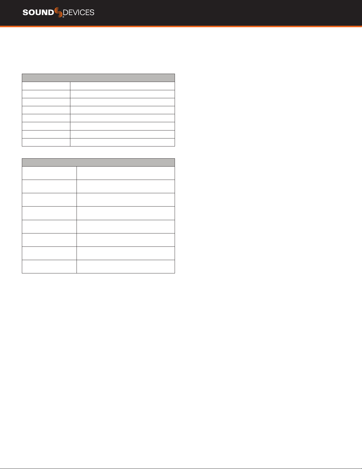
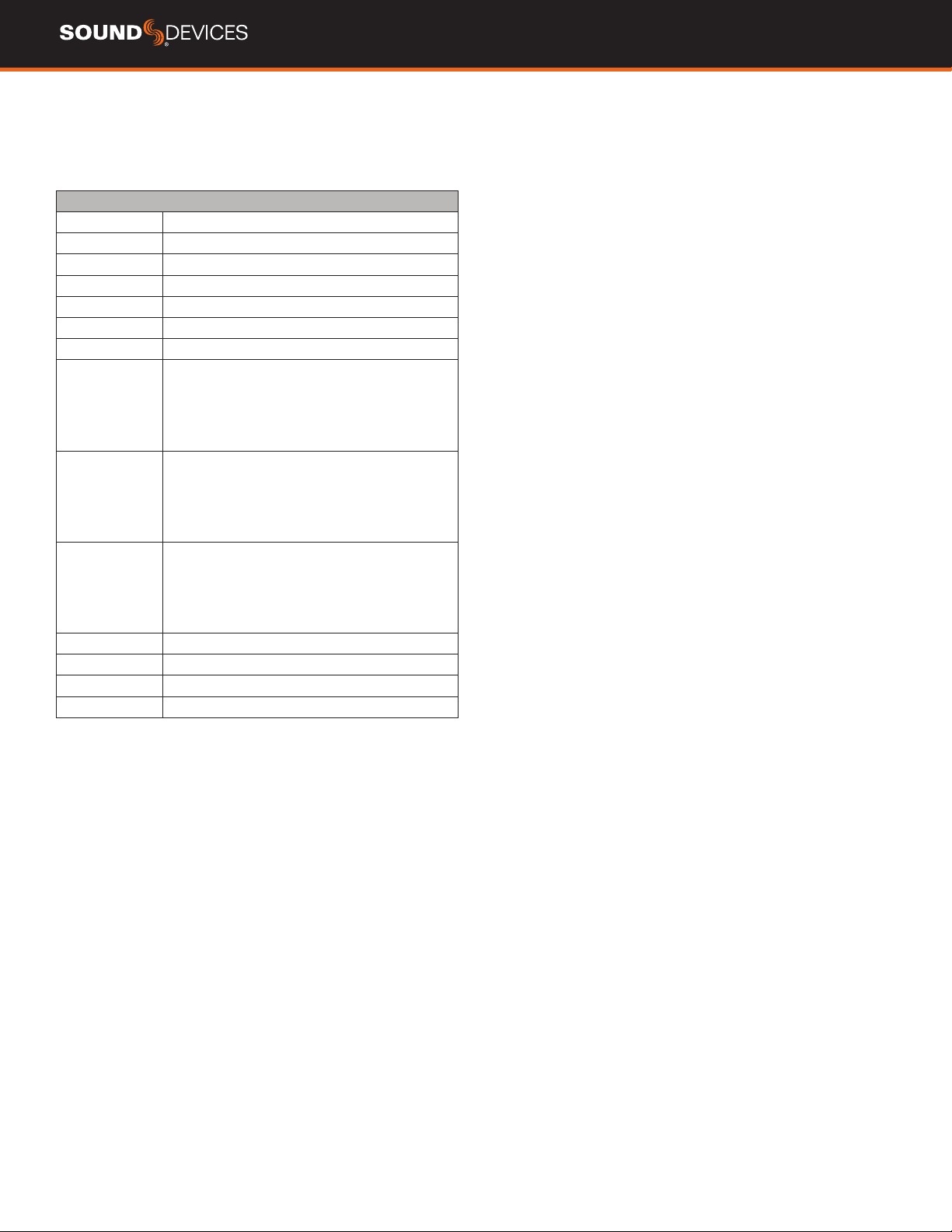
SD-Remote
SD-Remote is an Android tablet application, available in the Google
Play Store, designed to pair with the 888. SD-Remote offers control
and display parameters, including the following:
1. Channel Meters
2. L/R Meters
3. Channel Name
4. Channel Solos/Mutes
5. Channel Record Arm/Disarm
6. Transport Controls
7. Metadata Editing
8. Info
9. Timecode
10. Take List
11. Reports
SETUP PROCEDURE
1. Download and install SD-Remote from the Google Play Store.
2. Connect Android tablet to the 888 via USB-A port.
3. On the Android tablet, open the quick settings drop down menu.
4. Touch “USB Android System” twice to open “Use USB to” dialog
box.
5. Touch “Connect a MIDI device.”
6. Open SD-Remote app.
“
No USB Connection” popup will appear when
SD-Remote does not detect presence of an 888.
SD-Remote
Meter View
888 User Guide
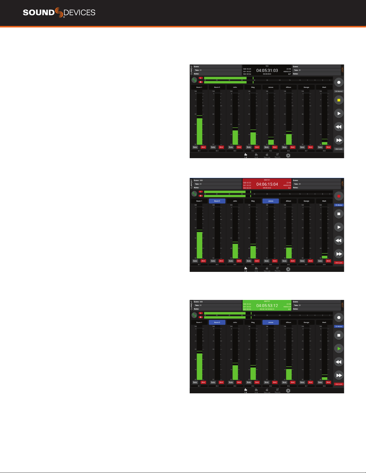
36
SD-Remote
Take List
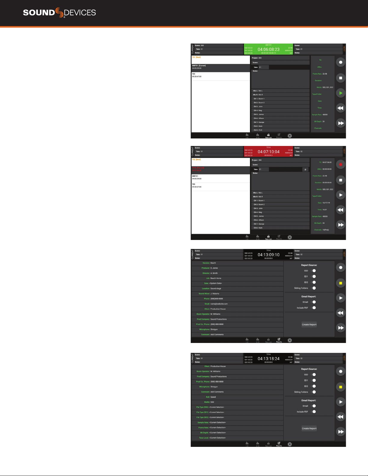
SD-Remote
Sound Report
CREATE SOUND REPORT
1. Touch “Reports” icon on the bottom of the screen.
2. Select the source(s) from which the desired info resides. Sibling
folders (folders at the same directory level) may be included in the
same report by selecting ”Sibling Folders”.
3. Select“Email” to email as CSV le. Additionally, a PDF le may be
mailed by selecting the “Include PDF” option.
4. Touch the “Create Report” button. The Sound Report(s) will be
placed into a ZIP le to be emailed while simultaneously creating the
report on the selected source drives.
888 User Guide
37
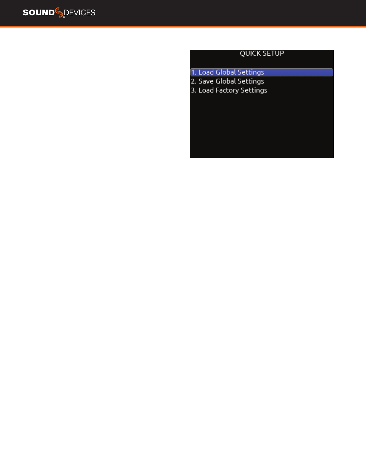
Quick Setup
LOAD GLOBAL SETTINGS Selects a saved settings le for loading.
[User-saved Global Settings]
SAVE GLOBAL SETTINGS Saves Global Settings to various
destinations. [SSD Drive (internal), INT1-4 (internal), SD1 and SD2]
LOAD FACTORY SETTINGS Selects Factory Settings to be loaded
for entire unit.

888 User Guide
38
The 888 is capable of connecting to a Dante network, simultaneously
receiving and sending up to 16 channels of audio at sample
rates from 44.1kHz up to 192 kHz. 888 channels 1-16 may be
sourced from Dante receive channels 1-16. Each Dante input
may be selected as a source in the Channel Setup menu. Each
Dante output may be sourced from ISOs (pre- or post-), Buses
and Outputs (post-delay). All network routing should be done
through Audinate’s Dante Controller application, found at www.
audinate.com. Once the initial conguration has been performed,
the 888 will keep its Dante conguration through power cycles. It
is recommended that, in most situations, the 888 is selected as
“Preferred Master” under the “Clock Status” tab of Dante Controller.
USB-A
USB-A allows multiple devices to be used to control and monitor vari-
ous functions of the 888. Should multiple devices be used simultane-
ously, the use of a USB-A type hub is required.
USB-C
USB-C allows for high-speed le transfer between a computer and any
of the 888’s media.
All other functionality is suspended in USB File Transfer mode.

888 User Guide
39
Specications
Specications are subject to change without prior notice.
For the latest information available on all Sound Devices products,
visit our website: www.sounddevices.com.
FREQUENCY RESPONSE
10 Hz to 80 kHz ± 0.5 dB (192 kHz sample rate, re 1 kHz)
THD + NOISE
0.005% max (mic in, 1 kHz, 22 Hz–22 kHz BW, trim at 20, fader at 0,
-10 dBu in)
EQUIVALENT INPUT NOISE
-131 dBV (-129 dBu) max (mic in, A-weighting, 76 dB gain, 150 ohm
source impedance)
PROCESSING ENGINE
Highly extensible, full FPGA-based audio processing, 3 FPGAs
Six-way ARM multiprocessor system
64-bit audio processing precision
AUDIO OVER ETHERNET
Dante, AES67 compatible
16 channels in, 16 channels out (up to 192 kHz)
1 Gb/s Ethernet, 1 port, transformer-balanced
INPUTS
Mic/Line inputs: 8 total, all fully featured; 4 on full-size XLR, 4 on TA3
Mic-level inputs: (XLR, TA3): Class-A, discrete differential long-tail pair,
4k ohm input impedance
Line-level inputs: (XLR, TA3): active-balanced, 4k ohm input
impedance
48V phantom: full 10 mA to all 8 inputs simultaneously
AES3 or AES42 available on XLR input 1
AES42: +10 V, 250 mA available, mode-1, auto-ASRC
Rtn A (TA3): unbalanced 2-channel, 4k ohm input impedance
Rtn B (3.5 mm): unbalanced 2-channel, 4k ohm input impedance
Com Rtn (TA3) balanced, 1-channel, 8k ohm input impedance
External Slate Mic (TA5): balanced, 8k ohm input impedance, menu-
selectable 12 V phantom
MAXIMUM INPUT LEVEL
Mic: +8 dBu (2.0 Vrms)
Line: +28 dBu (19.5 Vrms)
Rtn A, B: +18 dBu (6.2 Vrms)
Com Rtn: +24 dBu (12.3 Vrms)
External Slate Mic: +12 dBu (3.2 Vrms)
HIGH-PASS FILTERS
Adjustable 10 Hz to 320 Hz, 18 dB/oct. 1st stage analog (before
preamp), 2nd stage digital.
LIMITERS
Limiters available at all channels, buses, headphones, for all sample
rates
Analog rst stage, all subsequent stages digital
Attack time: 1 ms
Release time: adjustable, 50 ms to 1000 ms
Threshold: adjustable, -2 dBFS to -12 dBFS
Selectable ratio: inf:1, 20:1, 18:1, 16:1, 14:1, 12:1, 10:1
DELAY
Channel Adjustable 0-50 ms
Output Adjustable 0-500 ms
MAXIMUM GAIN
Trim stage (mic input): 76 dB
Trim stage (line input): 50 dB
Fader stage: 16 dB
Bus stage: 16 dB
Headphone stage: 20 dB
Mic-to-Line: 108 dB
Mic-to-Headphone: 112 dB
TA5 (along with mic input pins) for single connection to headset + mic
High output, 4 ohm output impedance, 400 mW + 400 mW at each
connector, all individually driven
Compatible with headphones of any impedance
OUTPUTS
XLR (L, R) active-balanced, 250/3.2k/120 ohms (mic/-10/line)
TA3 (X1-X4) active-balanced, 250/3.2k/120 ohms (mic/-10/line)
3.5mm (X5, X6, X7, X8): unbalanced, stereo, 1.8k ohms
HEADPHONE OUTPUTS
¼”, 3.5 mm
TA5 (along with mic input pins) for single connection to headset + mic
High output, 4 ohm output impedance, 400 mW + 400 mW at each
connector, all individually driven
Compatible with headphones of any impedance
MAXIMUM OUTPUT LEVEL
(all into 10k load)
Line: +20 dBu (7.8 Vrms)
“-10”: +6 dBu (1.5 Vrms)
Mic: -20 dBu (0.078 Vrms)
X5/X6 Out: +6 dBu (1.5 Vrms)
Headphone outputs (¼”, TA5, X7/X8): +14 dBu (4.0 Vrms)
A/D CONVERTERS
32-bit, 120 dB, A-weighted dynamic range typical
Sampling rates 44.1 kHz, 47.952 kHz, 48 kHz, 48.048 kHz, 88.2 kHz,
96 kHz, 192 kHz
DIGITAL OUTPUTS
AES3 transformer-balanced, in pairs; 1-2 (XLR-L), 3-4 (XLR-R)
110 ohm, 2 V p-p, AES and S/PDIF compatible
RECORDING
Internal 256 GB SSD, two removable SD Cards
10% over-provisioned for optimum performance
Simultaneous recording to internal SSD and the two SD cards
exFAT formatting
20 tracks (16 ISO channels, 4 buses)
Broadcast WAV monophonic and polyphonic le format
64-bit WAV (RF64) monophonic and polyphonic; support for les > 4 G
AAC 2 track at 48 kHz, selectable bit rate 32, 64, 128, 192, 256 kbps
AUTOMATIC MIXING
Dugan Automixer up to 16-channels on left and right mix bus
MixAssist up to 16-channels on Left and Right bus
USB
USB-C (USB 3.1 type 1) for le transfer of internal SSD, both SD Cards
USB-A host for keyboard, external controller, external USB hubs
supported for connecting multiple devices

888 User Guide
40
TIMECODE AND SYNC
Modes Supported: Off, Rec Run, Free Run, 24h Run, External,
including External Auto-Record and Continuous modes.
Frame Rates: 23.98*, 24, 25, 29.97 DF, 29.97 ND, 30 DF, 30 ND
Sample/Timecode Accuracy: 0.1 ppm (0.25 frames per 24 hours)
Timecode Input: 20k ohm impedance, 0.3 V - 3.0 V p-p (–17 dBu - +3
dBu)
Timecode Output: 75 ohm impedance, 5 V p-p (+12 dBu)
Word Clock Input: 10k/75 ohm selectable impedance, 1-5 V p-p input
sensitivity
Word Clock Output: 75 ohm impedance, 5 V p-p output, at SR
REMOTE CONTROL
Sound Devices CL-12 Linear Fader Controller
USB MIDI MCU Control - supported 3rd party fader controllers
SD-Remote Android app
USB Keyboard
External Timecode Record Trigger
LCD
320x240, transective, excellent sunlight visibility
Larger touchscreen display available via USB-connected SD-Remote
app
POWER
External: 10-18 V input on locking TA4 connector, pin-4 = (+), pin-1 =
(-)
Dual rear-mount Sony-style L-mount batteries with chargers
Current Draw, at 12 V no battery charging:
All mic preamps off: 0.90 A
All mic preamps on: 1.12 A
All mic preamps on, 192 kHz sample rate, recording to 2 SD Cards:
1.29 A
All mic preamps on, 192 kHz sample rate, recording to 2 SD Cards,
Dante enabled: 1.56 A
Intelligent power-down of unused mic preamps and other internal
circuits
Smart Battery telemetry supported via DC Input
ENVIRONMENTAL
Operating: -20° C to 60° C, 0 to 90% relative humidity (non-condens-
ing)
Storage: -40° C to 85° C
DIMENSIONS (H X W X D)
5.1 cm x 24.5 cm x 18.5 cm
2.0 in. x 10.0 in. x 7.3 in
WEIGHT
4.0 lbs (unpackaged, without batteries)
1.83 kg (unpackaged, without batteries)

888 User Guide
41
Glossary
¼-inch jack
Common analog audio connector used as both an audio input and
output. When a ¼-inch jack is described as TRS (tip-ring-sleeve) it
can be wired as either a balanced connection or as a two-channel
connection. ¼-inch headphone jacks are typically wired as TRS stereo
jacks.
3.5 mm jack
Common small-format audio connector. Often used for headphones
and -10 dBV signals for portable audio devices.
AES3
A standard for the exchange of digital audio signals between
professional audio devices. An AES3 signal can carry two channels of
PCM audio over balanced, 110 ohm interconnections. AES3 is most
commonly interconnected with XLR-3 cables.
AES42
A digital interface protocol for microphones and microphone inputs.
Microphones conforming to this standard directly output digital audio
through an XLR or XLD male connector, rather than producing an
analog output. AES42 microphones require powering.
Attenuation
A reduction in the level of an audio signal. Attenuation can be
applied to both analog and digital signals. A fader is used primarily
to attenuate signals, though a small amount of positive gain is often
available on a fader.
Bext chunk
Broadcast WAV extension data added to the audio data in a WAV le.
The bext chunk includes timecode and user bit data. For systems that
do not recognize the bext chunk this additional information is ignored.
Bit depth
When converting between analog and PCM digital audio the
amplitude of an analog signal is measured in nite steps, measured
in bits. Higher bit rates result in greater resolution of amplitudes,
resulting in higher dynamic range. 24-bit audio, with a theoretical
maximum dynamic range of 144 dB, is the standard bit depth used
throughout the audio chain for production.
Broadcast WAV, BWAV
Broadcast WAV les are WAV les with additional, non-audio data,
such as bEXT chunk data. Broadcast WAV les offer timecode
support.
Bus
An audio path that is the destination of one or multiple (mixed)
channels. A bus is typically routed to an output, a record track, or
both.
Camera return
An audio input on a mixer designed to receive the output, typically the
headphone output, of a camera. Camera return inputs allow the user
to monitor the level and quality of the signal received at the camera.
On the 888, the camera returns can be used as a source for any
channel.
Channel
A “slot” of a mixer that is controllable and routable. A given input
feeds the channel and the channel’s settings process and route the
audio as required. It can also be thought of as the path its selected
input signal takes on its way to its record track, a bus, or an output.
Channel grouping
With the 888, any of the 16 channels can be grouped together so
that their faders, record arming state mute states can be controlled
together. Channel grouping can be used as an alternative to sending
channels to a bus.
Circled take
An identifying character, the @ symbol, which is placed in the le
name to highlight a take. Circled takes can either be used to identify
good takes or to identify tracks or takes that will be ignored.
Com return
A dedicated audio input designed to receive signals from a PL, or
private line communications circuit. The com return on the 888 can
routed to an output or a bus.
Com send
A dedicated output designed to send signal to a PL (private line,
talkback) communications circuit. The com send is toggled by a front
panel switch.
Dante
A combination of software, hardware, and network protocols that
deliver uncompressed, multi-channel, low-latency digital audio over a
standard Ethernet network using Layer 3 IP packets.
dBFS
A measurement of the signal level of a digital signal in dB increments,
dB relative to full scale signal. The maximum signal in dBFS is 0
dBFS, with signals expressed with a negative sign. dBFS signal
strength is an internal measurement and does not correspond to
analog signals unless the relationship between analog signal and
digital signal is known.
Delay (channel)
Time delay that can be applied to an individual channel. Channel
delay, typically set in milliseconds, is often used to compensate for
different acoustical or electrical arrival times of signals between
channels.

888 User Guide
42
Ethernet
A family of computer networking technologies. Ethernet commonly
refers to the physical interconnection of the network typically using
twisted-pair copper connections on CAT cable with RJ-45 connectors.
Common Ethernet data speeds include 10 Mbs, 100 Mbs, and 1000
Mbs.
exFAT
A storage volume format that can be read and written from current
versions of MacOS and Windows. exFat supports volume sizes up to
128 PB (gigantic), and individual les can have a maximum size of 16
EB (even more gigantic, bigger than the maximum volume size).
Fader
A physical control on a mixing console, either a rotary or sliding
potentiometer, that controls the level of a channel to a bus. Most
faders have more attenuation than gain available and a unity gain
position where the input trim level established the level to the bus.
False take
A recorded take that was either erroneously recorded, or a take that
needs to be repeated. It can be labeled after recording. An identied
false take is moved to the trash bin and the auto-incrementing take
number is reset to the value prior to the false take.
File list
Every le recorded by a recorder is visible in the le list. It can be
viewed either on a recorder or from a computer when the recording
volume is mounted. The le list shows all the individual les recorded
by a recorder.
Frame rate
The rate at which video or motion picture images are recorded or
played back, measured in frames-per second (FPS). All audio and
video devices must be running at the same frame rate to keep audio
and video synchronized. Timecode frame rates are either an integer
or non-integer value. Integer values include 24, 25, and 30 FPS. Non-
integer frame rates include 23.976 and 29.97, and 29.97 drop FPS.
Frequency
The period at which a wave oscillates, measured in hertz (Hz).
Frequencies audible to humans range from 20 Hz for very low
frequency signals to 20 kHz for very high frequency signals.
Gain
An increase (or decrease with negative gain) in the level of an audio
signal. Gain can be applied in several locations, to both analog
and digital signals. In a eld mixer the microphone preamplier
provides a substantial amount of gain at the trim to raise the low
level microphone signal to a usable signal in the mixer. Gain is also
available at the fader. Gain of digital signals or line level analog
signals is often limited. Unity gain is gain stage that neither adds or
subtracts level from a signal.
Headphone monitor
Often a separate bus with a dedicated headphone volume control,
the headphone monitor typically is normalled to the main left/right
output bus of a mixer. Headphone sources can often be selected
among soloed tracks or buses. In some products complex headphone
monitoring of MS Stereo, LR stereo, and ambisonic sources is
available.
High pass lter (audio)
Also referred to as a low-cut lter, this circuit reduces the amount of
low frequency content in an audio signal. A HPF is particularly useful
when recording speech since the human voice does not generate
appreciable energy at low frequencies. The HPF reduces non-speech
signals such as environmental noise, wind noise, and microphone
handling noise, improving the intelligibility of speech and reducing low
frequencies from overloading the input. The high pass lter is placed
in the circuit close to the microphone preamplier.
High pass lters are often frequency selectable, ranging from 20 Hz to
200 Hz. HPF also have a slope, generally from 3 dB/octave to 18 dB/
octave. Greater/steeper slopes offer more attenuation of frequencies
just below the set lter frequency.
Input
The physical connection and associated signal type from external
sources connected to a device. Inputs can include microphone inputs
on XLR connectors, Dante inputs on audio-over-Ethernet, and USB
audio inputs from a computer. Depending on the architecture of the
mixing console its inputs may be hardwired to channels or channels
can be selected from different inputs.
Input limiter
A limiter circuit reduces the peak signal levels of audio, generally to
prevent signal overload. Analog inputs have a maximum input signal
level that can be reached before overload/distortion is introduced.
Setting the input gain correctly so that input signals do not reach this
maximum level prevents most overload conditions. In the presence of
very high, unexpected signals an input limiter changes the gain of the
incoming signal and prevents it from overloading. Input limiters are
sometimes compressor-type circuits with a ratio of innity:1, meaning
that any increase to the input signal into the limiter at the limiter
threshold does not increase the output signal of the limiter.
Several parameters may be available in a limiter, including knee, ratio,
release, and threshold.
Isolated track
A recorded track of an individual microphone or sound source. “ISO”
recordings allow for post-record mixing of individual sound elements.
iXML
An extensible data schema for audio and related metadata stored
in broadcast WAV les. Manufacturer-specic data generated during
recording is stored in iXML.
Line level
An analog audio signal used to interconnect audio equipment. Line
level may be balanced or unbalanced, referenced to +4 dBu or -10
dBV, professional or consumer respectively.
Low cut lter
See high pass lter.
Microphone level
The audio signal generated by a microphone. Mic level signals are
very low level, requiring a microphone preamplier to bring them to
usable, line levels. Interconnects with microphone level signals can be
subject to noise and interference.

888 User Guide
43
Mid-side linking (inputs)
When mid-side (MS) stereo inputs are used and the inputs are set to
MS linking and MS decoder is activated for those inputs. This yields
a stereo signal with one fader controlling overall input level and the
other fader controlling the “width”, or amount of the side signal
added. With an MS matrix at the input, the signal is sent to an output
bus as left/right stereo. Mixers with MS matrices often allow for
discrete mid and side signal recording. In that case the MS decoder
can be activated at the headphone selection to monitor left/right
stereo.
Mix track
A recorded track that is a sum of multiple tracks. In production sound
the mix track is often a single summed track of all production dialog
elements. Mix tracks can also be sub-mixes of like microphones, such
as a sub mix of just lavalier microphones or just boom microphones.
Monophonic WAV
A WAV le that is comprised of a single track of audio. When recording
multi-track audio with monophonic WAV les each track is recorded
to its own WAV le, with a le name indicating the track number. All
associated monophonic les that are part of a multi-track recording
will be identical lengths.
Mute
A mute control is a convenient on/off switch for a channel and an
easy way to remove a channel from appearing in downstream buses.
Mute an input or channel does not change levels or settings; when
channels are muted and unmuted, their settings remain.
Notes (metadata)
A metadata eld that is saved along with audio data in a recorded
sound le, useful for sound report generation. Some workstation
software recognizes the notes eld and presents it when viewing the
sound le.
Output
The physical connection and associated signal type sent from a
device. Outputs can be source from inputs, buses, record tracks, and
other auxiliary signals.
Output auto-mute
When set, an output signal is muted when recording is stopped,
restricting program audio from being sent to listeners “between
takes”.
Output delay
A digital delay applied at the output. Signal delay is often set at an
output to compensate for the delay introduced by digital imaging
systems so that picture and sound remain in correct “lip sync”. Output
delay is set in either frames or milliseconds.
Pan
When a channel is routed to a stereo-linked bus the level it appears at
each bus is adjusted by a pan control. A channel with its pan control
“straight up the center”, or “centered” sends signal at the same level
to each bus. A channel that is panned left or right sends the signal to
the left or right bus, respectively.
PFL, pre-fade listen
When an input or channel is selected for monitoring/solo with a PFL,
the channel is routed to the headphone output before the channel
fader so that the fader position has no effect on the headphone level.
Trim/gain changes to the input will change the headphone output.
Phantom power
Condenser (capacitor) microphones require power for operation. They
use power to charge the diaphragm backplate (for true condensers)
and power the impedance convert located adjacent to the
microphone capsule. Phantom power is the method for microphone
inputs to supply DC power to the microphone through the same
connection used for the audio signals from the microphone.
Phantom power provides a positive voltage, typically between 11-52
VDC, with 48 V being the most common, on both pin-2 and pin-3 with
pin-1 used as ground. The DC voltage appears as a common-mode
signal on the balanced connection and is rejected by the connection’s
differential amplier. Phantom power has no effect on dynamic
microphones.
Phase
The relationship one audio signal has in time with respect to another
audio signal, dened in degrees of phase. When audio signals are
generated at identical times, they are “in phase” with each other.
When one audio signal is time-delayed with respect to another the
signals are “out of phase”. Differing phase relationships can be
introduced several ways, including when microphones are placed at
varying distances from a sound source, or electrical/digital delay is
introduced to one signal with respect to another.
Phrase
A pre-set text string which can be used to quickly ll out the notes
eld.
Pre-fader routing
The signal from a channel is routed to a bus before the fader in the
signal path. The input trim, if available, controls the channel level sent
to the bus. Isolated tracks are typically recorded pre-fader so that any
level changes made to the faders don’t affect the recorded signal.
Pre-roll
A continuous buffer that is always writing to memory offering a
recording that begins prior to when the record button is activated.
Pre-roll is set in seconds, and the recording begins the set number
of seconds prior to the button being pressed. This is helpful in
applications where an operator missed a cue to begin recording.
Polarity (audio)
The direction of the current ow of an audio signal is dened as
polarity. The polarity of a signal can reversed when a balanced audio
signal connection has its pin-2 and pin-3 connections reversed.
Single-ended signals can have their polarity reversed when going
through an “inverting” gain stage. It is best practice to have all
incoming and outgoing signals with the same polarity relationship.
Polyphonic WAV
An individual WAV le that contains multiple audio tracks. When
recording multi-track audio with polyphonic WAV les all recorded
tracks are contained within a single WAV le.
Post-fader routing (after fade routing, AFL)
The signal from a channel is routed to a bus after the fader in the
signal path. The fader controls the level of the channel at the bus.
Channels sent to a master bus, such as the left/right bus, are
typically sent post-fader.

888 User Guide
44
Post-roll
An extra period of time that is appended to the end of a recording
when stop is pressed. If record is pressed during this period of
time, recording will resume within the same le with no audio lost.
This is particularly useful should a Director call ‘cut’ prematurely or
accidentally.
Project
An option available for le organization on Sound Devices recorders.
Projects are the highest level of le folder organization. The project
folder can contain sub-folders of scene les or recorded les directly.
Record bell
A tone generated in headphones to alert the listener that recording
has started. The bell is also produced when recording has ended with
the stop button, when the recording volume is full, or when power is in
a critical state.
Sampling rate
When converting between analog and PCM digital audio the analog
signal is measured (sampled) in unique steps at a data rate specied
in kHz. Higher sampling rates allow for representing higher frequency
analog audio. 48 kHz is the standard sampling rate for production,
worldwide. Higher sampling rates including 96 kHz and 192 kHz are
used for high-precision applications where the representation of audio
above 20 kHz is required. A general rule is that the maximum analog
audio frequency is ½ the sampling rate.
Scene
On Sound Devices recorders the scene becomes part of the le
name for a take. Scene names can be pre-loaded to quickly change
between scenes.
Slate microphone
A microphone, built-in or external microphone, on an audio mixer used
to notate takes or communicate with sound team members by the
mixer’s user speaking into the microphone. Slate microphones are
often routable to buses or tracks.
Stereo linking (inputs)
When active for stereo sources such as stereo microphones, linked
inputs are hard panned to the left and right bus. Controls including
gain (trim), fader, high pass lter, delay, limiter, mute, and routing are
controlled together.
Sticky Notes
Notes that persist to subsequent takes.
Solo
A control on a mixer to route a channel to headphones while muting
all others. Solo and PFL are related controls and in many consoles are
the same. Solo circuits can be exclusive—only one channel is sent to
headphones at a time—or non-exclusive—any number of channels can
be sent to the solo circuit and appear in headphones.
TA-type connector (TA3, TA4, TA5, TA6)
Miniature XLR-type, locking connectors. TA3 connectors are used
by Sound Devices for various inputs, outputs, and as balanced and
unbalanced connections. TA4 connectors are used by Sound Devices
for DC power connections to the 888 mixer-recorder. TA4 is also used
for audio connections from lavalier microphones to some wireless
transmitters. Ta5 connectors are used for Mic/Line inputs and the
headset on the 888. TA6 connectors are presently not used by
Sound Devices though they are used for audio connections by other
manufacturers.
Take
A recorded take is an individual recorded le (or les when recording
monophonic WAV les) generated by a recorder. Take numbers are
auto-incrementing. Take numbers are added to the end of the le
name.
Take list
Separate from a le list, a take list consolidates related les such
as a group of monophonic WAV les generated by a single take and
presents them as a single take.
Test tone
See tone oscillator.
Timecode
A numerical clock value expressed in hours:minutes:seconds:frames,
i.e. 04:59:39:05, used to synchronize cameras, video decks,
and audio recorders. Timecode requires clocks on devices to be
synchronized, either through a wired or wireless connection between
devices, or through a process called “jam sync” where each device,
which requires a high-precision clock, runs independently after their
clocks are synchronized.
Timecode mode
Sound Devices recorders offer multiple timecode modes. Different
modes correspond to different timecode workows. Common modes
available in Sound Devices recorders include:
Record run - timecode advances only when recording is engaged.
Free run - timecode run continuously, typically with the start of
production being at 0 hour.
24 hour - similar to free run except the start time corresponds to time-
of-day.
Ext TC - the recorder applies the value of an external timecode source.
Tone oscillator
A sound generator producing a sine wave tone at a given frequency at
a given output level. With its known output level tone oscillators are
helpful to set gain structure between audio equipment.
Track
A single recorded audio signal. Common recorded tracks are the main
left/right master audio bus and isolated (ISO) channel recordings. ISO
tracks are typically identied by the channel of the same number, e.g.
channel 1 is sent to track 1, channel 2 is sent to track 2, etc.
Track arm
Tracks that are active and ready for recording are said to be “armed”.
When recording begins all armed tracks begin recording. Depending
on the production is may be advantageous to arm and disarm tracks,
especially to disarm unused tracks.
Track name
Individual tracks of a multi-track recording can be named to indicate
microphone type or character name.
Trim
Also dened in mixers as “gain”, the trim adjustment is the rst
stage of gain of a microphone or line level input. Typical microphone
trim values range from 10 dB to 50 dB, depending on microphone
sensitivity and volume of the sound source.

888 User Guide
45
User bits
Static, numeric data that is available as part of a timecode signal.
User bits are often used to indicate the date of a le. User bits are
four sets of two-digit hexadecimal numbers from 00 to ff.
WAV File
A universal, well-supported le type for sound le recordings. WAV les
can contain one or more (up to 65,535) tracks of PCM audio data at
any sampling rate and bit depth. A standard WAV le is limited to a
maximum le size of 4 GB. Sound Devices uses the WAV extension for
recorded les, including for les with Broadcast WAV metadata and
WAV RF64 les.
WAV RF64
An extension of the WAV le type that supports le sizes larger than 4
GB. When recording high track count, high sampling rate polyphonic
WAV les, the 4 GB size limitation of WAV can be reached quickly.
RF64 les larger than 4 GB require recording to a volume type than
can support le sizes larger than 4 GB.
Word clock
A reference signal used to synchronize the sampling rate of multiple
digital devices.
XLR female
Industry-standard 3-pin locking audio connector for microphone and
line-level sources. Predominantly used as an input. Also shown as
XLR-F
XLR male
Industry-standard 3-pin locking audio connector for microphone and
line-level sources. Predominantly used as an output. Also shown as
XLR-M

888 User Guide
46
FCC & ISED Compliance Statements
This device complies with part 15 of the FCC Rules. Operation is subject to the following two conditions: (1)
This device may not cause harmful interference, and (2) this device must accept any interference received,
including interference that may cause undesired operation.
Changes or modications not expressly approved by the manufacturer could void the user’s authority to
operate the equipment.
This device contains transmitter module FCC ID: XF6-M7DB6
This device contains transmitter module IC: 8407A-M7DB6
FCC Interference Statement
This equipment has been tested and found to comply with the limits for a Class B digital device, pursuant to
part 15 of the FCC Rules. These limits are designed to provide reasonable protection against harmful inter-
ference in a residential installation. This equipment generates, uses and can radiate radio frequency energy
and, if not installed and used in accordance with the instructions, may cause harmful interference to radio
communications. However, there is no guarantee that interference will not occur in a particular installation.
If this equipment does cause harmful interference to radio or television reception, which can be determined
by turning the equipment off and on, the user is encouraged to try to correct the interference by one or
more of the following measures:
—Reorient or relocate the receiving antenna.
—Increase the separation between the equipment and receiver.
—Connect the equipment into an outlet on a circuit different from that to which the receiver is connected.
—Consult the dealer or an experienced radio/TV technician for help.
FCC & ISED User Statement
This device complies with FCC and ISED RF exposure limits for general population / uncontrolled environments.
Cet appareil est conforme à la norme FCC et ISED les limites d’exposition pour la population
générale / l’exposition incontrôlée.
A separation distance of at least 20cm must be maintained between the antenna and all persons. This device
must not be co-located with any other antenna or transmitter.
This device (containing FCC ID: XF6-M7DB6, IC: 8407A-M7DB6) has been approved to operate with the
antenna type listed below:
Model: GW.71.5153 Type: 2.4/5.8GHz Dipole Antenna
Manufacturer: Taoglas Max. Gain: 3.8dBi (2.4GHz), 5.5dBi (5.8GHz)
No change to the antenna type is permitted. Any change to the antenna could result in the device exceeding
the RF exposure requirements and void the user’s authority to operate the device.
This Device complies with Industry Canada License-exempt RSS standard(s). Operation is subject to the
following two conditions: 1) this device may not cause interference, and 2) this device must accept any in-
terference, including interference that may cause undesired operation of the device.
Cet appareil est conforme avec Industrie Canada, exempts de licence standard RSS (s). Son fonctionne-
ment est soumis aux deux conditions suivantes: 1) ce dispositif ne peut pas causer d’interférences, et 2)
ce dispositif doit accepter toute interférence, y compris les interférences qui peuvent causer un mauvais
fonctionnement de l’appareil.
Incorrect use of batteries poses a danger of explosion. Replace only with the same or equivalent type.
Properly recycle batteries. Do not crush, disassemble, incinerate, dispose in a re or expose batteries to high
temperatures.
888 User Guide
47
Declaration of Conformity
Manufacturer’s Name: Sound Devices, LLC
Manufacturer’s Address: E7556 State Road 23 and 33
Reedsburg, WI 53959 USA
Declares under sole responsibility that the product as delivered
Product Name: 888
Model Number: 888
Description: Portable Mixer-Recorder
Product Options: This declaration covers all options of the above product.
Complies with the essential requirements of the following applicable European Directives,
and carries the CE marking accordingly:
Radio Equipment Directive (2014/53/EU)
Article 3.1b:
ETSI EN 301 489-17 v3.1.1
EN 55032:2012
EN 55032:2/AC:2013
CISPR 32:2012
EN 55103-2:2009
Article 3.2:
ETSI EN 300 328 v2.1.1
This Declaration of Conformity applies to the above-listed product(s) placed on the EU market
after:
October 7, 2019
Date Matt Anderson - Sound Devices, LLC President

888 User Guide
48
This product incorporates software subject to the BSD license:
Copyright 2001-2010 Georges Menie (www.menie.org)
All rights reserved. Redistribution and use in source and
binary forms, with or without modication, are permitted
provided that the following conditions are met
* Redistributions of source code must retain the above copyright
notice, this list of conditions and the following disclaimer.
* Redistributions in binary form must reproduce the above copyright
notice, this list of conditions and the following disclaimer in the
documentation and/or other materials provided with the distribution.
* Neither the name of the University of California,
Berkeley nor the names of its contributors may be
used to endorse or promote products derived from this
software without specic prior written permission.
* THIS SOFTWARE IS PROVIDED BY THE REGENTS AND
CONTRIBUTORS ``AS IS’’ AND ANY EXPRESS OR IMPLIED
WARRANTIES, INCLUDING, BUT NOT LIMITED TO, THE IMPLIED
WARRANTIES OF MERCHANTABILITY AND FITNESS FOR A
PARTICULAR PURPOSE ARE DISCLAIMED. IN NO EVENT SHALL
THE REGENTS AND CONTRIBUTORS BE LIABLE FOR ANY DIRECT,
INDIRECT, INCIDENTAL, SPECIAL, EXEMPLARY, OR CONSEQUENTIAL
DAMAGES (INCLUDING, BUT NOT LIMITED TO, PROCUREMENT
OF SUBSTITUTE GOODS OR SERVICES; LOSS OF USE, DATA, OR
PROFITS; OR BUSINESS INTERRUPTION) HOWEVER CAUSED AND
ON ANY THEORY OF LIABILITY, WHETHER IN CONTRACT, STRICT
LIABILITY, OR TORT (INCLUDING NEGLIGENCE OR OTHERWISE)
ARISING IN ANY WAY OUT OF THE USE OF THIS SOFTWARE,
EVEN IF ADVISED OF THE POSSIBILITY OF SUCH DAMAGE.
Two Level Segregated Fit memory allocator, version 3.1.
Written by Matthew Conte
Http://tlsf.baisoku.org
Based on the original documentation by Miguel Masmano:
http://www.gii.upv.es/tlsf/main/docs
This implementation was written to the specication of
the document, therefore no GPL restrictions apply.
Copyright (c) 2006-2016, Matthew Conte All rights reserved.
Redistribution and use in source and binary forms,
with or without modication, are permitted provided
that the following conditions are met:
* Redistributions of source code must retain the above copyright
notice, this list of conditions and the following disclaimer.
* Redistributions in binary form must reproduce the above copyright
notice, this list of conditions and the following disclaimer in the
documentation and/or other materials provided with the distribution.
* Neither the name of the copyright holder nor the names of its
contributors may be used to endorse or promote products derived
from this software without specic prior written permission.
** THIS SOFTWARE IS PROVIDED BY THE COPYRIGHT
HOLDERS AND CONTRIBUTORS “AS IS” AND
ANY EXPRESS OR IMPLIED WARRANTIES, INCLUDING,
BUT NOT LIMITED TO, THE IMPLIED
WARRANTIES OF MERCHANTABILITY AND FITNESS FOR A PARTICULAR
PURPOSE ARE DISCLAIMED. IN NO EVENT SHALL MATTHEW CONTE
BE LIABLE FOR ANY DIRECT, INDIRECT, INCIDENTAL, SPECIAL,
EXEMPLARY, OR CONSEQUENTIAL DAMAGE (INCLUDING, BUT NOT
LIMITED TO, PROCUREMENT OF SUBSTITUTE GOODS OR SERVICES;
LOSS OF USE, DATA, OR PROFITS; OR BUSINESS INTERRUPTION)
HOWEVER CAUSED AND ON ANY THEORY OF LIABILITY, WHETHER
IN CONTRACT, STRICT LIABILITY, OR TORT (INCLUDING NEGLIGENCE
OR OTHERWISE) ARISING IN ANY WAY OUT OF THE USE OF THIS
SOFTWARE, EVEN IF ADVISED OF THE POSSIBILITY OF SUCH DAMAGE.

Post Ofce Box 576
E7556 State Rd. 23 and 33
Reedsburg, Wisconsin 53959 USA
+1 608.524.0625 main
+1 608.524.0655 fax
800.505.0625 toll free
www.
sounddevices.com