Loading ...
Loading ...
Loading ...
16
E
7.
Where the beam appears on the left wall, mark point A, and where the beam
appears on the right wall mark point B.
8.
Turn the laser unit 180º so that the Y-axis points directly toward the
opposite wall (Figure
M
2
).
9.
Allow the laser unit to self-level.
10.
Where the beam appears on the left wall, mark point AA, and where the beam
appears on the right wall mark point BB.
11.
Calculate the Total Error using the following equation:
Total Error = (AA-A) - (BB-B)
12.
If your Total Error measurement is greater than the Allowable Error for
the corresponding Distance Between Walls in the following table, the laser
must be serviced at an authorized service center.
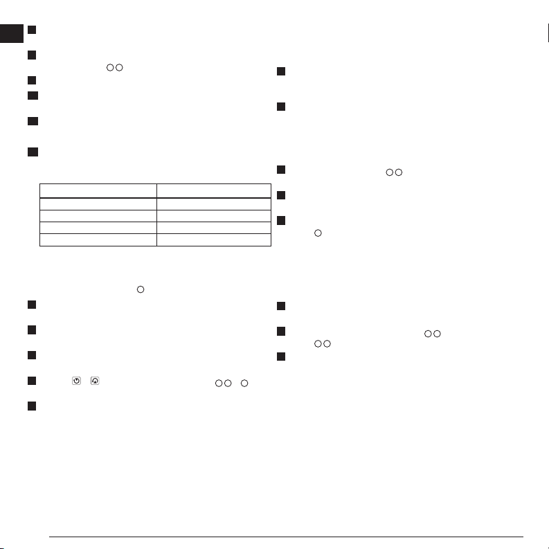
L (Distance Between Walls) Allowable Error
40′ (15m) 3/64” (1.5mm)
50′ (20m) 1/16” (2mm)
70′ (25m) 3/32” (2.5mm)
100′ (30m) 1/8” (3mm)
Plumb Error Check
Perform this check using a wall that is no shorter than the tallest wall for which
this rotary laser will be used (Figure
N
).
1.
Using a standard plumb bob as a reference, mark the top and bottom of a
wall. (Be sure to mark the wall and not the oor or ceiling).
2.
Position the rotary laser securely on the oor approximately 3” (1m) from
the wall.
3.
Turn the laser on and point the laser dot at the mark on the bottom of
the wall.
4.
Using the or arrow on the Remote Control (Figure
B
6
or
7
),
rotate the dot upwards.
5.
If the center of the dot scans over the mark on the top of the wall, the laser
is properly calibrated.
Using the Laser
Using the Laser on a Tripod
1.
Position a tripod securely and set it to the desired height. Make sure that
the tripod has a 5/8”-11 threaded screw to ensure secure mounting of the
laser unit.
2.
Make sure that the top of the tripod is roughly level.
• The laser will self-level only if the top of the tripod is within ± 5˚ of level.
• If the laser is set up too far out of level, it will beep when it reaches the
limit of its leveling range. No damage will be done to the laser, but it will
not operate in an “out of level” condition.
3.
Attach a tripod adapter (Figure
G
1
) to the laser unit. The adapter may be
assembled to the bottom for level mode or to the side for plumb mode.
4.
Place the laser with the attached adapter on the tripod and screw the
threaded knob on the tripod into the female thread on the tripod adapter.
5.
Turn the laser on and adjust the rotation speed and controls, as desired
(Figure
O
).
Using the Laser on a Floor
The laser level can be positioned directly on the floor for leveling and plumbing
applications such as framing walls.
1.
Place the laser on a relatively smooth and level surface where it will not be
disturbed or exposed to vibration.
2.
Position the laser for a level setting (Figure
H
1
) or a plumb sertting
(Figure
H
2
).
3.
Turn the laser on and adjust the rotation speed and controls, as desired.
NOTE:
The laser will be easier to set up for wall applications if the rotation speed
is set to 0RPMs and the remote control is used to line up the laser with
control marks. The remote allows one person to set up the laser.
Loading ...
Loading ...
Loading ...