PoulanPi O !
Instruction Manual
Manual de Instrucciones
Manuel d'lnstructions
PPB150E
For Occasional Use Only
WARNING:
Read and foIIow all Safety Rules and Operating Instructbns before
using this product. Failure to do so can result in serious injury.
ADVERTENOIA:
Lea et manual de instrucciones y siga todas Ias advertencias e
instrucciones de seguridad. Et no hacerlo puede resuttar en Ie-
siones graves.
AVERTISSEMENT:
Lire le manuel d'instructions et bien respecter tous tes avertisse-
ments et routes les instructions de securit& Tout defaut de le
faire pourrait entra_ner des blessures graves,
Poutan PRO
1030 Stevens Creek Road
Augusta, GA 30907
545186744 Rev, 2 5/5/08 BRW
These attachments used in combination with the specified powerhead have been evaluated to
ANSI B1753-2003, "Grass Trimmers and Brushcutters - Safety Requirements".
Powerhead including trimmer attachment .............................. PPB150E
Brusbeutter attachment ............................................. PPB4000C
These attachments used in combination with the specified powerhead have been evaluated to
applicable ISO and EN safety requirement standards by the Swedish Machinery Testing _nsfltute:
Edger attachment .................................................. PPB1000E
Culflvator attachment ............................................... PPB2000T
Blower attachment ................................................. PPB3000B
Pruner attachment ................................................. PPB5000P
dDiWARNING: When using gardening
appliances, basic safety precautions must al-
ways be foJlowed to reduce the risk of fire and
serious injury. Read and follow all instruc-
tions
This power unit can be dangerous] Operator is
responsible for following instructions and warn-
ings on unit and in manual Read entire insfruc-
tJon manual before using unit! Be thoroughly fa-
miliar with the controis and the proper use o{ the
unit. Restbet the use of this unitto persons who
have read, understand, and w*ll folfew the
insbuctions and warnings on the unit and in the
manual Never allow children to operate this
un*t.
INSTRUCTION SAFETY INFORMATION
MANUAL ON THE UNIT
'_ DANGER: Never use blades with line
trimmer attachment. Never use flailing de-
vices with any attachment. This unit (when
used with supplied line trimmer attachment) is
designed for line trimmer use onIy. Use of any
other accessories with Iine trimmer attach-
ment will increase the risk of injury.
Q©©
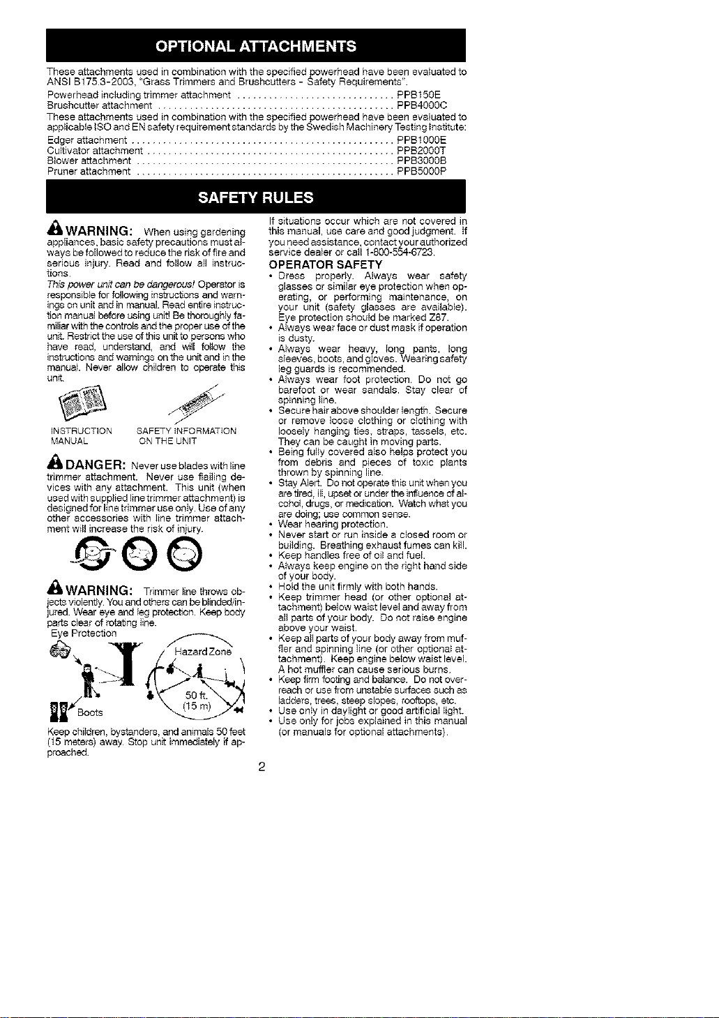
ill WARNING: Trimmer line throws ob-
jects vlolenfly You and others can be blioded4n-
jured Wear eye and leg protec_on. Keep body
parts clear of rotating Iine.
Eye Protection
Keep children, bystanders, and animals 50 feet
(t5 meters) away Stop unit immediately _ ap-
proached.
If situations occur which are not covered in
this manual, use care and good judgment. If
you need assistance, contact you rauthorized
service dealer or call 1-800-554-6723
OPERATOR SAFETY
• Dress properly. Always wear safety
glasses or similar eye protection when op-
erating, or performing matntenance, on
your unit (safety glasses are available).
Eye protection should be marked Z87.
• Always wear face or dust mask if operaflon
is dusty.
• Always wear heavy, Song pants, long
sleeves, boots, and gloves. Wearing safety
leg guards is recommended.
• Always wear foot protection Do not go
barefoot or wear sandals. Stay clear of
spinning line.
• Secure hair above shoulder length Secure
or remove loose clothing or clothing with
loosely hanging ties, straps, tassels, etc.
They can be caught in moving parts.
• Being fully covered aIso helps protect you
from debris and pieces of toxic plants
thrown by spinning line.
• Stay Alert. Do not operate this unit when you
are tired, ilI, upset or under the influence of al-
cohol, drugs, or medication. Watch what you
are doing; use comrqon sense.
• Wear hearing protection.
• Never start or run inside a closed room or
building. Breathing exhaust fumes can kill.
• Keep handles free of oil and fuel.
• A}ways keep engine on the right hand side
of your body.
• Hold the unit firmly with both hands.
• Keep trimmer head (or other optional at-
tachment) below waist level and away from
all parts of your body. Do not raise engine
above your waist.
• Keep all parts of your body away from muf-
fler and spinning Sine (or other opbena_ at-
tachment) Keep engine below waist level.
A hot muffler can cause serious burns
• Keep firm footing and balance. Do not over-
reach or use from unstabfe surfaces such as
ladders, trees, steep slobes, rooftops, etc.
• Use onIy in daylight or good artiflciaI Sight.
• Use only for jobs explained in this manuaI
(or manuals for optional attachments)
UNIT/ MAINTENANCE SAFETY
• Disconnect the spark plug before perform-
ing maintenance except carburetor adjust-
ments.
• Look for and replace damaged or loose
parts before each use Look for and repair
fuel leaks before use. Keep ingood working
condition.
• Replace tbmmer head parts that are
chipped, cracked, broken, or damaged in
any other way before using the unit.
• Maintain unit according to recommended pro-
cedures. Keep cutting line at proper Iength.
• Use only 0.080" (2 mm) diameter Poulan
PRO brand line. Never use wire, rope, string,
etc.
• kTstall required shield propedy before using
the unit. Use only specified trimmer head:
make sure it is propedy installed and se-
curely fastened.
• Make sure unit is assembled correcfly as
shown in this manual.
• Make carburetor adjustments with lower
end supported to prevent line from contact-
ing any object.
• Keep others away when making carburetor
adjustments.
• Use only recommended Poulan PRO ac-
cessories and replacement parts
• Have nil maintenance and service not ex-
plained in this manual performed by an au-
thorized service dealer.
FUEL SAFETY
• Mix and pour fuel outdoors.
• Keep away from sparks or flames.
• Use a container approved for fuel
• Do not smoke or allow smoking near fuel or
the unit.
• Avoid spilling fuel or oil Wipe up ali fuel
spills
• Move at Ieast 10 feet (3 meters) away from
fueling site before starting engine.
• Stop engine and aliow to cool before re-
moving fuel cap.
• Always store gasoIine in a container ap-
proved for flammabIe }iquids.
TRANSPORTING AND STORAGE
• Allow engine to cool before stodng or trans-
porting in vehicle.
• Empty the fuel tank before storing or trans-
porting the unit. Use up fuel ]eft in the carbu-
retor by starting the engine and letting it run
until it stops.
• Store unit and fuel in area where fuel vapors
cannot reach sparks or open flames from wa-
ter heaters, e]ectY{c motors or sw_tches, fur-
naces, etc.
• Store unit so line limiter blade cannot acci-
dentalIy cause injury The unit can be hung
by the shaft.
• Store unit out of reach of children
_WAftll%llNr_: The engine exhaust
from this product contains chemicals known
to the State of California to cause cancer, birth
defects or other reproductive harm.
SAFETY NOTICE: Exposure to vibrations
through prolonged use of gasoline powered
hand tools could cause blood vesset or nerve
damage in the fingers, hands and joints of
people prone to circulation disorders or ab-
normal swellings. Prolonged use in cold
weather has been linked to blood vessel dam-
age in otherwise healthy people. Ifsymptoms
occur such as numbness, pain, loss of
strength, change in skin color or texture, or
loss of feeling in the fingers, hands, or joints,
discontinue the use of this tool and seek med-
icaI attention. An anti-vibration system does
not guarantee the avoidance of these prob-
lems. Users who operate power tools on a
continuaI and regular basis must monitor
closely their physical condition and the condi-
tion of this took
SPECIAL NOTICE: This unit is equipped
with a temperature limiting muffler and spark
arresting screen which meets the require-
ments of California Codes 4-442 and 4443. All
U.S. forest land and the states of California,
Idaho, Maine, Minnesota. New Jersey, Ore-
gon, and Washington require by law that
many internal combustion engines be
equipped with aspark arresting screen. Ifyou
operate in a Iocale where such regulations ex-
ist, you are IegaIly responsible for maintaining
the operating condition ofthese parts. Failure
to do so is a violation of the law. For normal
homeowner use, the muffler and spark arrest-
ing screen will not require any service After
50 hours of use, we recommend that your
muffler be serviced or replaced by an autho-
rized service dealer.
LINE TRIMMER SAFETY
'_&WARNING: Inspect the area to be
trimmed before each use Remove objects
(recks, broken glass, nails, wire, etc.) which
can be thrown by or become entangled in line.
Hard objects can damage the trimmer head
and be thrown causing serious injury.
• Use only for trimming, scalping, mowing and
sweeping. Do not use for edging, pruning or
hedge trimming
• Cut from your right to your left. Cutting on
left side of the shield will throw debris away
from the operator.
ADDITIONAL SAFETY RULES
FOR OPTIONAL ATTACHMENTS
_WAftINII%I(_: For each optional at-
tachment used, read entire instruction manu-
aI before use and follow all warnings and in-
structions in manual and on attachment.
_,WARNING: Ensure handlebar is
installed when using brushcutter attachment.
Attach handlebar above arrow on safety labeI
on the upper shaft (engine end of unit). Ifyour
brushcutter attachment does not inctude a
handlebar, a handlebar accessory kit
(#53007145t) is available from your autho-
rized service dealer.
EDGER SAFETY
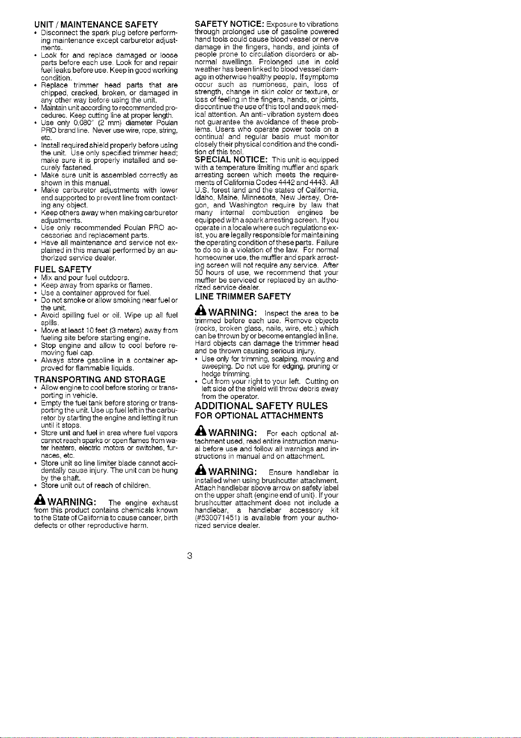
WARNING: Inspect the area to be
edged before each use. Remove objects
(rocks, broken glass, nails, wire, etc) which
can be thrown by the blade or can wrap
around the shaft.
• Blade rotates momentarily after the trigger
is released. The blade can seriousty cut
you or others.
• Allow blade to stop before removing it from
the cut.
Blade rotates
after the
• Throw away blades that are bent, warped,
cracked, broken or damaged in any other
way. Replace parts that are cracked,
chipped, or damaged before using the unit.
• Do not attempt to remove cut material nor
hold material to be cut when the engine is
running or when cutting blade is moving.
• Always keep the wheel and depth adjusting
skid in contact with the ground.
• Always push the unit slowIy over the
ground. Stay alert for uneven sidewalks,
holes in the terrain, _arge roots, etc.
BLOWER/VACUUM SAFETY
dI_kWARNING: Inspect area before
starting unit. Remove all debris and hard ob-
jects such as rocks, glass, wire, etc. that can
ricochet, be thrown, or otherwise cause injury
or damage during operation.
• Do not set unit on any surface except a
clean, hard area while engine is running.
Debris such as gravel, sand, dust, grass,
etc, couid be picked up by the air intake
and thrown out through discharge opening,
damaging unit property, or causing serious
injury to bystanders or operator
• Never place objects inside the blower
tubes, vacuum tubes or blower outlet. AI-
ways direct the blowing debris away from
people animals, glass, and solid objects
such as trees, automobiles, wa_ls, etc. The
force of air can cause rocks, dirt, or sticks to
be thrown or to ricochet which can hurt
peopIe or animals, break glass, or cause
other damage.
• Never run unit without the proper equip-
ment attached. When using your unit as a
blower, aIways install blower tubes.
• Check air intake opening, blower tubes or
vacuum tubes frequently, always with en-
gine stopped and spark plug disconnected.
Keep vents and discharge tubes free of de-
bris which can accumuIate and restrict
proper air flow.
• Never place any obiect in air intake opening
as this could restrict proper air flow aRd
cause damage to the unit.
• Never use for spreading chemicals, fertiliz-
ers, or other substances which may contain
toxic matedais.
• To avoid spreading fire, do not use near Ieaf
or brush fires, fireplaces, barbecue pits,
ashtrays, etc
BRUSHCUTTER SAFETY
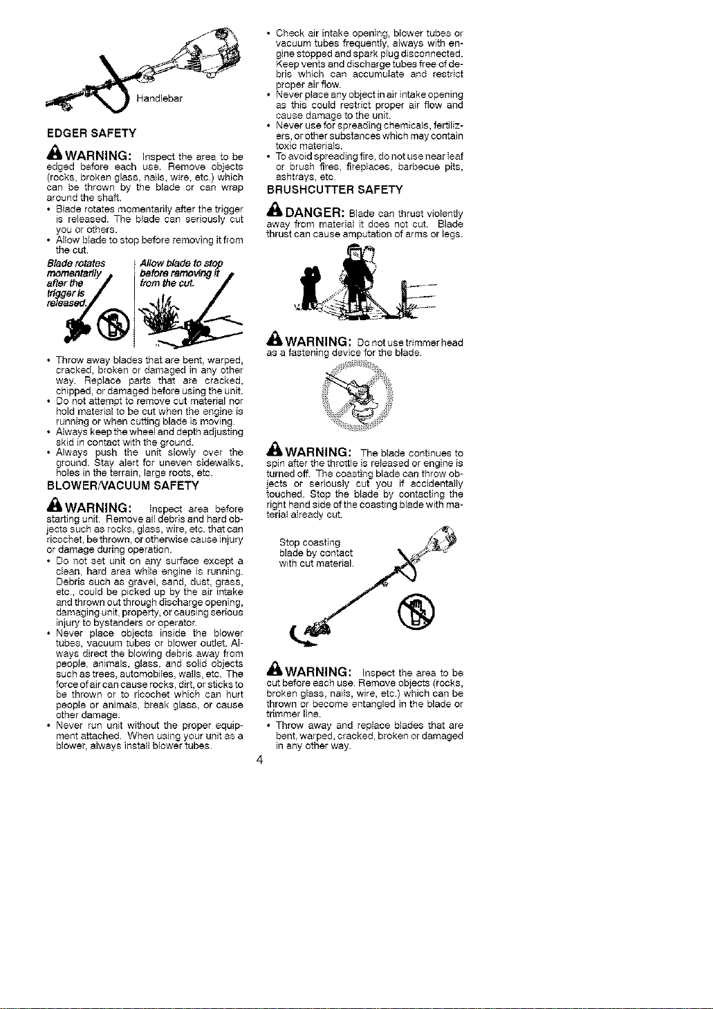
DANGER: Blade can thrust violently
away from matedal it does not cut. Blade
thrust can cause amputation of arms or legs.
_L WARNING: Do notuse trimmer head
as a fastening device for the blade
£, ------.....A
4_WAtdNINr_: The blade continues to
spin after the throttle is released or engine is
turned off. The coasting blade can throw ob-
jects or seriously cut you if accidentally
touched. Stop the blade by contacting the
right hand side of the coasting blade with ma-
teria_ aIready cut.
Stop coasting
blade by contact
with cut material
®
,CA
DWARNING: Inspect the area to be
cut before each use. Remove objects (rocks,
broken glass, nails, wire, etc.) which can be
thrown or become entangled in the blade or
trimmer line.
• Throw away and replace blades that are
bent, warped, cracked, broken or damaged
in any other way.
4
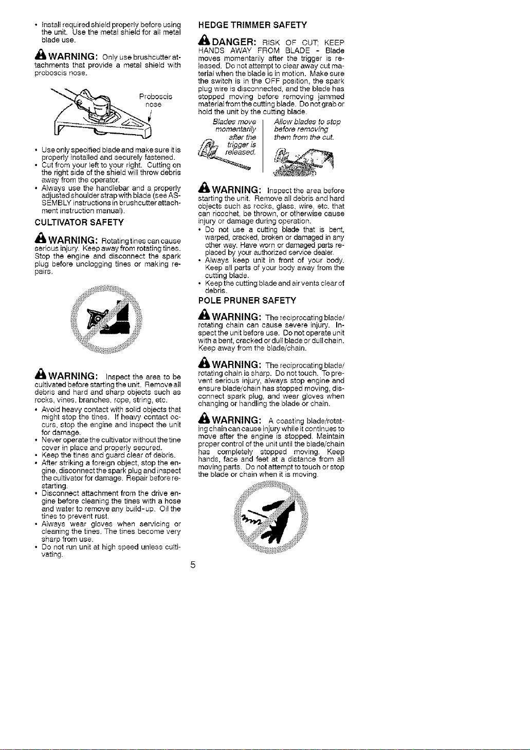
• thstallrequiredshieldproperlybeforeusing
theunit.UsethemetalshieIdforaIImetal
bladeuse.
_;i, WARNING: Onlyusebrushcutterat-
tachmentsthat provide a metal shield with
proboscis nose.
Proboscis
n_se
• Use only specified blade and make sure it is
properly installed and securely fastened.
• Cutfromyourlefttoyourdght Cuttingon
the right side of the shield will throw debris
away from the operator.
• Always use the handlebar and a property
adjusted shoulder strap with blade (see AS-
SEMBLY instructions in brushcutter attach-
ment instruction manual).
CULTIVATOR SAFETY
_ WARNING: Rotatingtines can cause
serious injury Keep away from rotating tines.
Stop the engine and disconnect the spark
plug before uncIogging tines or making re-
pairs.
ilWAI-iNIN_: Inspect the area to be
cultivated before starting the unit. Remove all
debris and hard and sharp objects such as
rocks, vines, branches, rope, string, etc.
• Avoid heavy contact with solid objects that
might stop the tines. If heavy contact oc-
curs, stop the engine and inspect the unit
for damage.
• Never operate the cultivator without thetine
cover in place and properly secured.
• Keep the tines and guard clear of debris.
• After striking a foreign object, stop the en-
gine, disconnect the spark plug and inspect
the cultivator for damage. Repair before re-
starting.
• Disconnect attachment from the drive en-
gine before cleaning the tines with a hose
and water to remove any build-up OiI the
tines to prevent rust.
• Always wear gloves when servicing or
cleaning the tines The tines become very
sharp from use
• Do not run unit at high speed unless eutti-
vating.
HEDGE TRIMMER SAFETY
dI_UANLiI::I'{: RiSK OF CUT; KEEP
HANDS AWAY PROM BLADE - Blade
moves momentarily after the trigger is re-
leased. Do not attempt to ciear away cut ma-
teda_ when the blade is in motion. Make sure
the switch is in the OFF position, the spark
plug wire is disconnected, and the blade has
stopped moving before removing jammed
material from the cutting blade. Do not grab or
hotd the unit by the cutting blade
Blades move Allow blades to stop
momentarily before removing
after the them from the cut.
trigger is
WARNING: Inspect the area before
starting the unit Remove all debris and hard
objects such as rocks g_ass, wire, etc. that
can ricochet, be thrown, or otherwise cause
injury or damage during operation.
• Do not use a cutting blade that is bent,
warped, cracked, broken or damaged in any
other way Rave worn or damaged parts re-
placed by your authorized service dealer.
• Always keep unit in front of your body.
Keep a_l parts of your body away from the
cutting blade.
• Keep the cutting blade and air vents clear of
debris
POLE PRUNER SAFETY
_L WARNING: The reciprocating blade/
rotating chain can cause severe injury. In-
spect the unit before use. Do not operate unit
with a bent, cracked or duII blade or dull chain.
Keep away from the blade/chain.
_,WARNING: The reciprocating blade/
rotating chain is sharp. Do not touch. To pre-
vent serious injury, always stop engine and
ensure blade!chain has stopped moving, dis-
connect spark plug, and wear gioves when
changing or handling the blade or chain.
_ WARNING: A coasting blede/rotat-
ing chain can cause injury whileit continues to
move after the engine is stopped. Maintain
proper control of the unit until the blade/chain
has completely stopped moving. Keep
hands, face and feet at a distance from all
moving parts. Do not attempt to touch or stop
the blade or chain when it is moving
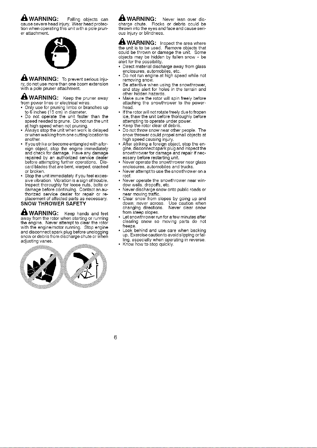
4111WAHNINLi: FalIing objects can
cause severe head injury. Wear head protec-
tion when operating this unit with a pole prun-
er attachment.
_11,WARNING: Topreventsedousinju-
ry,do not use more than one boom extension
with a pole pruner attachment.
_I_WARNING: Keep the pruner away
from power lines or electrical wires
• Only use for pruning limbs or branches up
to 6 inches (15 cm) in diameter
• Do not operate the unit faster than the
speed needed to prune. Do not run the unit
at high speed when not pruning.
• Always stop the unit when work is delayed
or when walking from one cutting Iocation to
another
• {fyou stdke or become entangled with afor-
eign object, stop the engine immediately
and check for damage. Have any damage
repaired by an authorized service dealer
before attempting further operations. Dis-
card blades that are bent. warped, cracked
or broken.
• Stop the unit immediately if you feel exces-
sive vibration Vibration is a sign of trouble.
inspect thoroughly for loose nuts, bolts or
damage before continuing. Contact an au-
thorized service dealer for repair or re-
placement of affected parts as necessary.
SNOW THROWER SAFETY
_{I_WARNING: Keep hands and feet
away from the rotor when starting or running
the engine. Never attempt to clear the rotor
with the engine!motor running. Stop engine
and disconnect spark plug before unclogging
snow or debris from discharge chute or when
adjusting vanes.
41_WAHNINr_: Never _ean over dis-
charge chute Rocks or debris could be
thrown into the eyes and face and cause seri-
ous injury or bIindness
_ WARNING: Inspecttheareawhere
the unit is to be used. Remove objects that
could be thrown or damage the unit. Some
objects may be hidden by fallen snow - be
alert for the possibility.
• Direct matedal discharge away from glass
enclosures, automobiles, etc.
• Do not run engine at high speed while not
removing snow.
• Be attentive when using the snowthrower,
and stay alert for holes in the terrain and
other hidden hazards.
• Make sure the rotor will spin freely before
attaching the snowthrower to the power-
head.
• tf the rotor will not rotate freely due to frozen
ice, thaw the unit before thoroughIy before
attempting to operate under power.
• Keep the rotor clear of debds.
• Do not throw snow near other people. The
snow thrower could propel small objects at
high speed causing injury.
• After striking a foreign object, stop the en-
gine, disconnect spark plug and inspect the
snowthrower for damage and repair if nec-
essary before restarting unit.
• Never operate the snowthrower near glass
enclosures, automobiles and trucks.
• Never attempt to use the snowthrower on a
roof.
• Never operate the snowthrower near win-
dow wells dropoffs, etc.
• Never discharge snow onto public roads or
near moving traffic.
• Clear snow from slopes by going up and
down; never across. Use caution when
changing directions Never clear snow
from steep s}opes.
• Let snowthrower run for a few minutes after
cleadng snow so moving parts do not
freeze.
• Look behind and use care when backing
up. Exercise caution to avoid slipping or fal-
ling, especialIy when operating in reverse.
• Know how to stop quickly.
_k WARNING: If received assembled,
repeat all steps to ensure your unit is properly
assembled and al_fasteners are secure.
Examine parts for damage. Do not use dam-
aged parts
NOTE: If you need assistance or find parts
missing or damaged, call f-800-554-6723.
It is normal for the fue_ fi_ter to raft]e h_the
empty fuel tank.
Finding fuel or oil residue on muffler is normal
due to carburetor adjustments and testing
done by the manufacturer
INSTALLING TRIMMER ATTACH-
MENT
CAUTION: When installing trimmer attach-
ment, place the unit on a fiat surface for stabil-
ity.
1. Loosen the coupler by turning the knob
counterc$ockwise.
Coupler
Shipping
protector
Knob
TIGHTEN
2. Remove shipping protector fromcoupler.
3. Remove the shaft cap from the trimmer
attachment (if present).
g. Position Iocking/reIease button of attach-
ment into guide recess of coupler
5. Push the attachment intothe coupler until
the locking/release button snaps into the
primary hole.
6. Before using the unit, tighten the knob se-
curely by turning clockwise
Coupler Primary Hole
i_uide Recess
Button
_ WARNING: Make sure the locking/
release button is Iocked in the primary hole
and the knob is securely tightened before op-
erating the unit. All attachments are designed
to be used in the primary hole unless otherwise
stated in the applicable attachment instruction
manual. Using the wrong hole could lead to seri-
ous injury or damage to the unit.
Secondary Hole
Locking/Release
Button in Primary Hole
For optional attachments, see the AS-
SEMBLY section of the applicable attach-
ment instruction manual
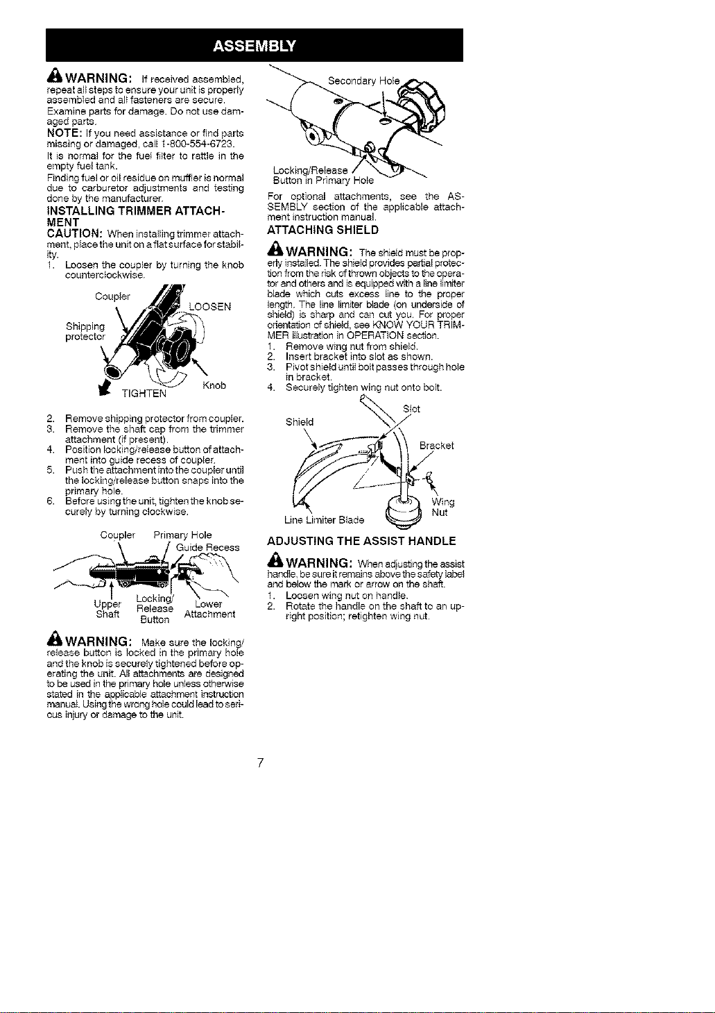
ATTACHING SHIELD
,_ WARNING: Theshieldmustbeprop-
erlyinstalled. The sNeld provides pertial protec-
tion from the risk of thrown objects to the opera-
tor and others and is equipped with a line limiter
blade which cuts excess Iine to the proper
length. The line limitsr blade (on underside of
shield) is sharp and can cut you. For proper
orientation of shield, see KNOW YOUR TRIM-
MER illustration in OPERATION section.
1. Remove wing nut from shield.
2. Insert bracket into slot as shown.
3. Pivot shield until bolt passes through hoie
in bracket.
g. Securely tighten wing nut onto bolt.
Shield yot
Bracket
Une Limiter Blade ( _ NW_g
ADJUSTING THE ASSIST HANDLE
Jl_ WARNING: Whenadjustingtheassist
handIe, be sure itremains above the safety lapel
and below the mark or arrow on the shaft.
1. Loosen wing nut on handle.
2. Rotate the handle on the shaft to an Lip-
right position; retighten wing nut.
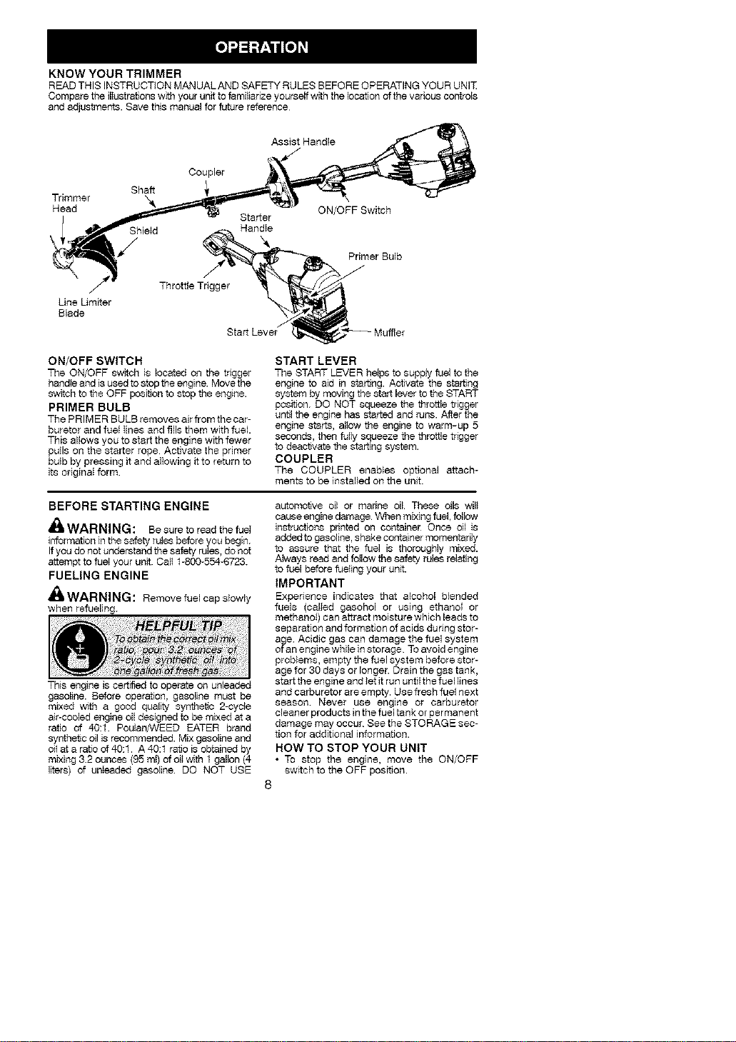
KNOW YOUR TRIMMER
READTHIS INSTRUCTION MANUALAND SAFETY RULES BEFOREOPERATINGYOUR UNIT
Compare the illustrefions with your unit to femilJedze yourself with the location of the various controls
and adjustments. Save this manual for future reference
Assist Handle
Shaft
Trimmer X&
Head
Shield
/
Coupler
Starter
Handfe
ON/OFF Switch
Primer Bulb
Throttle Trigger
Line Umiter
Blade
Start Lever
ON/OFF SWITCH
The ON/OFF switch is located on the tagger
beodfe and is used to stop the engine. Move the
switch to the OFF position to stop the engfne.
PRIMER BULB
The PRIMER BULB removes air from the car-
buretor and fuet Iines and fills them with fuel.
This allows you to start the engine with fewer
putls on the starter rope Activate the primer
butb by pressing it and alfewing it to return to
its edginaI form.
START LEVER
The START LEVER he_ps to supply fuel to the
engine to aid in starting. Activate the starting
system by moving the start lever to the START
position. DO NOT squeeze the throttle trigger
until the engine has started and runs. After the
engine starts, aifew the engine to warm-up 5
seconds, then fully squeeze the throttle trigger
to deactivate timestarting system.
COUPLER
The COUPLER enables optional attach-
meats to be installed on the unit.
BEFORE STARTING ENGINE
_lt WARNING: Be sure to read the fuef
information in the safety rules before you begin.
Ifyou do not understand the safety rufes, do not
attempt to fuel your unit. Call 1-800-554-672g.
FUELING ENGINE
WARNING: Remove fuel cap slowly
when refueling.
This engine is certified to operate on unleaded
gasoline. Before operation, gasoline must be
mixed wr_h a good quality synthetic 2-cycle
air-cooled engine oil designed to be mixed at a
ratio of 40:1. PoulanfCTEED EATER brand
syrrthet_c oil is recommended. Mix gasoline and
oi_at a ratio of 40:1. A 40:1 ratio is obtained by
mixing 3.2 ounces (95 rot) of oil with 1 gallon (4
liters) of unIeaded gasoline DO NOT USE
automotive oil or marine oil These oils will
cause engine damage When mixing fuel follow
instructions printed on container Once oil is
added to gasoline, shake container momentarily
to assure that the fuel is thoroughly mixed.
Always read and feflow the safety rules relating
to fuel before fuefing your unit.
IMPORTANT
Expenence indicates that alcohol blended
fuels (called gasobel or using ethanol or
methanef) can attract moisture which leads to
separation and formation of acids du ring stor-
age Acidic gas can damage the fuel system
of an engine while in storage To avoid engine
problems, empty the fuel system before stor-
age for 30 days or longer. Drain the gas tank,
start the engine and let Jtrun until the fuel lines
and carburetor are empty. Use fresh fuel next
season. Never use engine or carburetor
cleaner products inthe fuel tank or permanent
damage may occur See the STORAGE sec-
tion for additional information.
HOW TO STOP YOUR UNIT
• To stop the engine, move the ON/OFF
switch to the OFF position.
8
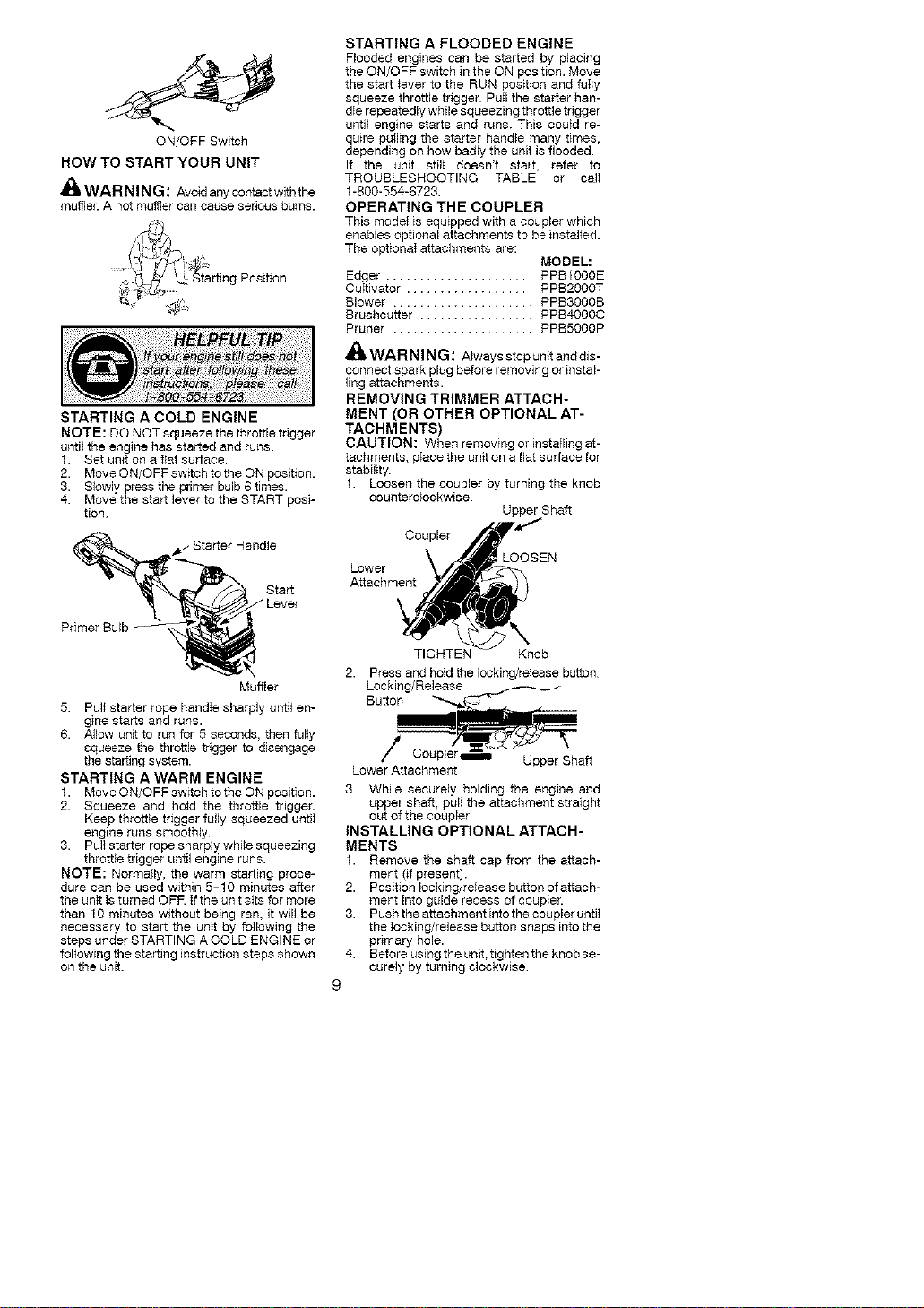
ON/OFFSwitch
HOWTOSTART YOUR UNIT
_ik WARNING: Avoidanycontactwiththe
muffle£ A hot muffler can cause serious burns.
Position
STARTING A COLD ENGINE
NOTE: DO NOT squeeze the throttle trigger
untiI the engine has started and runs.
1. Set unit on a flat surface.
2. Move ON/OFF switch to the ON position.
3. Slowly press the primer bulb 6 times.
4. Move the start lever to the START posi-
tion
_f- Starter Handle
Start
STARTING A FLOODED ENGINE
Flooded engines can be started by placing
the ON/OFF switch in the ON position. Move
the start _ever to the RUN position and fuIly
squeeze throttle trigger PuII the starter hun-
die repeatedly while squeezing throttle trigger
until engine starts and runs. This coutd re-
quire pulling the starter handle many times,
depending on how badly the unit is flooded.
If the unit stilI doesn't start, refer to
TROUBLESHOOTING TABLE or calI
1-800-554-6723.
OPERATING THE COUPLER
This model is equipped with a coupler which
enables optional attachments to be instalIed.
The optionaI attachments are:
MODEL:
Edger ...................... PPB1OOOE
CuItivator ................... PPB2000T
Blower ..................... PPB3000B
Brushcutter ................. PPB4.0O0C
Pruner ..................... PPB50OOP
_WARNING: A_ways stop unit and dis-
connect spark plug before removing or instal-
ling attachments.
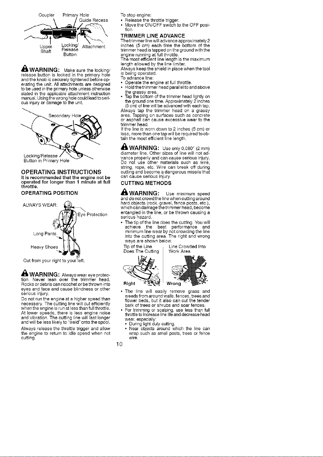
REMOVING TRIMMER ATTACH-
MENT (OR OTHER OPTIONAL AT-
TACHMENTS)
CAUTION: When removing or instaIling at-
tachments, piece the unit on a flat surface for
stability.
1. Loosen the coupler by turning the knob
counterclockwise.
Upper Shaft
Coupler
Lower
Attachment
Muffler
5. Puli starter rope handIe sharply untiI en-
gine starts and runs.
6. Allow unit to run for 5 seconds, then fully
squeeze the throttle trigger to disengage
tile starting system.
STARTING A WARM ENGINE
1. Move ON/OFF switch to the ON position.
2. Squeeze and hoId the throttle trigger.
Keep throttle trigger fully squeezed untiI
engine runs smoothly.
3. Pull starter rope sharply while squeezing
throttle trigger until engine runs.
NOTE: Normally, the warm starfing proce-
dure can be used within 5-10 minutes after
the unit is turned OFR If the unit sits for more
than 10 minutes without being ran, it will be
necessary to start the unit by following the
steps under STARTING A COLD ENGINE or
folIowing the starting instruction steps shown
on the unit.
TIGHTEN Knob
2. Press and hold the Iockthg/release button
Locking/Release
Button
/ P _ Upper Shaft
Lower Attachment
3. While securely holding the engine and
upper shaft, pull the attachment straight
out of the coupler
INSTALLING OPTIONAL ATTACH-
MENTS
1. Remove the shaft cap from the attach-
ment (if present).
2. Position locking/release button of attach-
meat into guide recess of coupler.
3. Push the attachment into the coupler until
the locking/release button snaps into the
primary hole.
4-. Before using the unit, tighten the knob se-
curely by turning clockwise
9
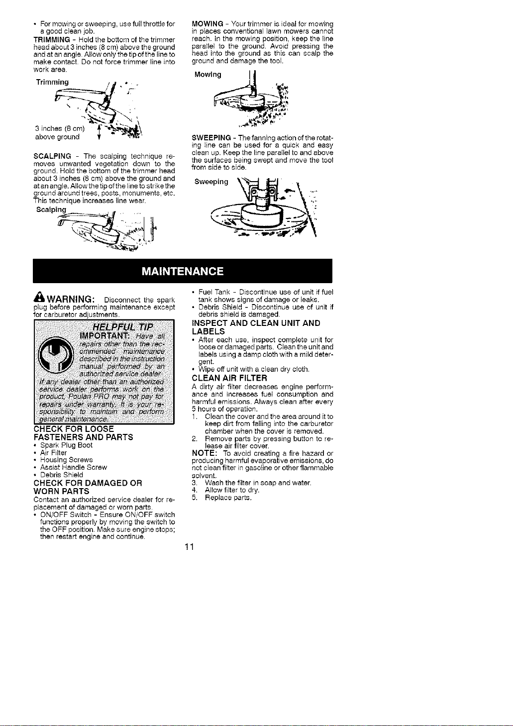
Coupler Pdmary Hole
Upper Locking/ Attachment
Shaft Release
Button
_k WARNING: Make sure the locking/
release button is _ocked in the primary hole
and the knob is securely tightened before op-
erating the unit. All attachments are designed
to be used in the pdmary hole unless otherwise
stated in the applicable attachment instruction
manual Using the wrong hoie could lead to seri-
ous injury or damage to the unit.
Secondary Hole
Locking
Button in Primary Hote
OPERATING INSTRUCTIONS
It is recommended that the engine not be
operated for longer than 1 minute at full
throttle.
OPERATING POSITION
ALWAYS WEAR:
Eye Protection
Long Pants ._.
Heavy Shoes !
Cut from your right to you_ ft
_l WARNING: Always wear eye protec-
tion. Never lean over the trimmer head.
Rocks or debris can ricochet or be thrown into
eyes and face and cause blindness or other
sedous injury.
Do not run the engine at a higher speed than
necessary. The cutting line wil_ cut efficienfly
when the engine is run at less than full throttle.
At lower speeds, there is less engine noise
and vibration. The cutting line will last longer
and wilI be less likely to 'weld" onto the spool.
Always release the throttle trigger and allow
the engine to return to idle speed when not
cutting.
To stop engine:
• Release the throttle trigger
• Move the ON/OFF switch to the OFF posi-
tion.
TRIMMER LINE ADVANCE
The trimmer line will advance approximately 2
inches (5 cm) each time the bottom of the
trimmer head is tapped on the ground with the
engine running at futl throttle.
The most efficient line length isthe maximum
length allowed by the line limiter.
Always keep the shield in place when the tool
is being operated
To advance Iine:
• Operate the engine at full throttle.
• Hold the tdmmer head parallelto and above
the grassy area.
• Tap the bottom of the trimmer head IJghtly on
the ground one time. Approximately 2 inches
(5 cm) of line will be advanced with each tap.
Always tap the trimmer head on a grassy
area. Tapping on surfaces such as concrete
or asphalt can cause excessive wear to the
trimmer head.
If the Iine is worn down to 2 inches (5 cm) or
less, more than one tap will be required to ob-
tain the most efficient Iine length.
_WARNING: Useonty0.O80" (2mm)
diameter Iine. Other sizes of line will not ad-
vance properly and can cause serious injury.
Do not use other materials such as wire,
string, rope, etc. Wire can break off during
cutting and become a dangerous missile that
can cause serfous injury.
CUTTING METHODS
iIWAI'ININLi: Use minimum speed
and do not crowd the line when cutting around
hard objects (rock, gravel, fence posts, etc),
which can damage the trimmer head, become
entangled in the _ine, or be thrown causing a
serious hazard.
• The tip of the line does the cutting. You wilI
achieve the best performance and
minimum Iine wear by not crowding the line
into the cutting area. The right and wrong
ways are shown below.
Tip of the Une Line Crowded into
Does The Cutting Work Area
• The line wilI easily remove grass and
weeds from around walls, fences, trees and
flower beds, but it also can cut the tender
bark of trees or shrubs and scar fences.
• For trimming or scalping, use less than fulI
throttle to increase line life and decrease head
wear, especially:
• During light duty cutting.
• Near objects around which the line can
wrap such as sma}l posts, trees or fence
wire.
10
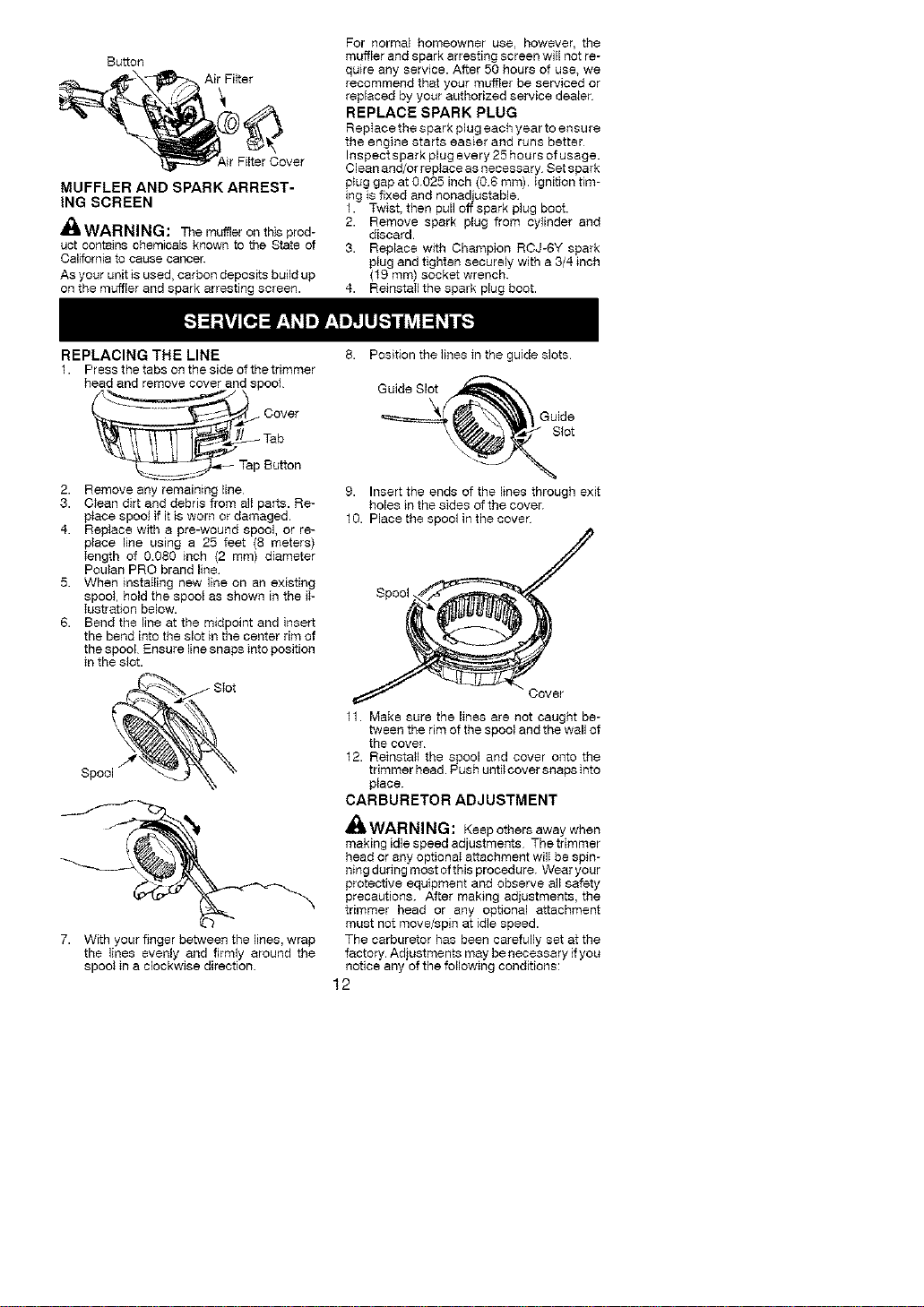
• For mowingor sweeping, use fulIthrottlefor
a good clean job.
TRIMMING - Hold the bottom of the trimmer
head about 3 inches (8 cm) above the ground
and at an angIe Allow only the tip of the line to
make contact• Do not force trimmer line into
work area•
Trimming / . * .
above ground ¥ - _'
SCALPING - The scalping technique re-
moves unwanted vegetation down to the
ground Hold the bottom of the trimmer head
about 3 inches (8 cm) above the ground and
atan angle. Allowthe fip ofthe line to strike the
ground around trees, posts, rqonuments, etc.
This technique increases line wear•
Scalping ,
MOWING - Your trimmer is ideal for mowing
in places conventional lawn mowers cannot
reach. In the mowing position, keep the line
para}lel to the ground• Avoid pressing the
head into the ground as this can scalp the
ground and damage the tool•
Mowin_
-- :_
SWEEPING - The fanning action of the rotat-
ing Iine can be used for a quick and easy
clean up. Keep the line para{lel to and above
the surfaces being swept and move the toot
from side to side•
Sweeping_
/nhWAItNINLi: Disconnect the spark
pIug before performing maintenance except
for carburetor adjustments.
CHECK FOR LOOSE
FASTENERS AND PARTS
• Spark Plug Boot
• Air Filter
• Housing Screws
• Assist Handle Screw
• Debris Shield
CHECK FOR DAMAGED OR
WORN PARTS
Contact an authorized service dealer for re-
placement of damaged or worn parts
• ON/OFF Switch - Ensure ON/OFF switch
functions properly by moving the switch to
the OFF position. Make sure engine stops;
then restart engine and continue
• Fuel Tank - Discontinue use of unit if fuel
tank shows signs of damage or leaks
• Debris Shield - Discontinue use of unit if
debris shield is damaged
INSPECT AND CLEAN UNIT AND
LABELS
• After each use, inspect complete unit for
loose or damaged parts• Clean the unit and
labels using a damp cloth with a mild deter-
gent.
• Wipe off unit w_th a clean dry cloth.
CLEAN AIR FILTER
A dirty air filter decreases engine perform-
ance and increases fuel consumption and
harmful emissions. Always clean after every
5 hours of operation•
1. Clean the cover and the area around it to
keep dirt from falling into the carburetor
chamber when the cover is removed.
2. Remove parts by pressing button to re-
lease air filter cover
NOTE: To avoid creating afire hazard or
producing harmful evaporative emissions, do
not clean fi_ter in gasoline or other flammable
solvent.
3. Wash the filter in soap and water•
4-. Allow filter to dry.
5. Replace parts
11
Button
MUFFLER AND SPARK ARREST-
ING SCREEN
,_kWARNING: The muffler on this prod-
uct contains chemicals known to the State of
California to cause cancer.
As your unit is used, carbon deposits build up
on the muffler and spark arresting screen.
For normal homeowner use, however, the
muffler and spark arresting screen will not re-
quire any service. After 50 hours of use, we
recommend that your muffler be serviced or
replaced by your authorized service dealer
REPLACE SPARK PLUG
RepIace the spark plug each year to ensure
the engine starts easier and runs better
Inspectspark plug every 25 hours of usage.
Clean and!or replace as necessary Set spark
p_ug gap at 0.025 inch (08 mm). Ignition tim-
ing is fixed and nonadjustable
1. Twist, then pull off spark plug boot.
2. Remove spark plug from cylinder and
discard.
3. Replace w_th Champion RcJ-eY spark
plug and tighten securely with a 3/4 inch
(f9 ram) socket wrench.
4. ReinstaIIthe spark plug boot.
REPLACING THE LINE
1. Press the tabs on the side of the trimmer
head and remove cover and spool
....... _ Cover
Tab
_-=_ Tap Button
2. Remove any remaining line
3. Ctean dirt and debris from all parts. Re-
piece spool ff it is worn or damaged.
4. Replace with a pre-wound spool, or re-
place line using a 25 feet (8 meters)
Iength of 0.080 inch (2 mm) diameter
Poulan PRO brand line
5. When instaIling new line on an existing
spool, hold the spool as shown in the iI-
Iustrafion below.
6. Bend the line at the midpoint and insert
the bend into the slot in the center rim of
the spool Ensure line snaps into position
in the slot.
7. With your finger between the lines, wrap
the lines evenly and firmly around the
spool in a clockwise direction.
8. Position the lines in the guide slots
Guide Sl__
9. Insert the ends of the lines through exit
holes in the sides of the cove_
10. Place the spool in the cove_
11. Make sure the lines are not caught be-
tween the rim of the spool and the wall of
the covei
12. Reinstall the spool and cover onto the
trimmer head. Push until cover snaps into
piece.
CARBURETOR ADJUSTMENT
_WARNING: Keepothersawaywhen
making idle speed adjustments The trimmer
head or any optionaI attachment wilI be spin-
ning during most of this procedure. Wear your
protective equipment and observe all safety
precautions. After making adjustments, the
trimmer head or any optional attachment
must not move/spin at idle speed.
The carburetor has been carefully set at the
factory. Adjustments may be necessary if you
notice any of the following conditions:
12
• Engine w*ll not idle when the throttIets
released.
• The trimmer head or any optional
attachment moves/spins at idle.
Make adjustments with the unit supported so
the cutting attachment is off the ground and
wiII not make contact with any object. Hold
the unit by hand while running and making ad-
justments. Keep a_lparts of your body away
from the cutting attachment and muft}er
Idle Speed Adjuetment
Allow engine to idle. Adjust speed until engine
runs without trimmer head or any optional at-
tachment moving or spinning (idle too fast) or
engine stalling (idle speed too slow).
• Turn idle speed screw clockwise to
increase engine speed if engine stalls or
dies.
• Turn idle speed screw counterclockwise to
decrease engine speed if trimmer head or
any optional attachment moves or spins at
idie.
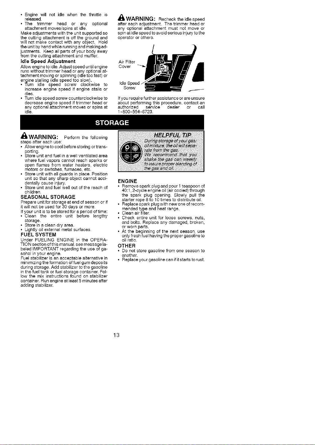
_WARNING: Rechecktheidlespeed
after each adjustment. The trimmer head or
any optional attachment must not move or
spin at idle speed to avoid serious injury to the
operator or others.
Air Filter
Cover
If you require further assistance or are unsure
about performing this procedure, contact an
authorized service dealer or calI
1-800-554-6723.
£', ...----.....A
tlIWAtrfNINS: Perform the following
steps after each use:
• Allow engine to cool before stodng or trans-
porting.
• Store unit and fuel in a well ventilated area
where fuel vapors cannot reach sparks or
open flames from water heaters, electbc
motors or switches, furnaces, etc.
• Store unit with all guards in place. Position
unit so that any sharp object cannot acci-
dentally cause injury.
• Store unit and fuel well out of the reach of
children.
SEASONAL STORAGE
Prepare unit for storage at end of season or if
it will not be used for 30 days or more
If your unit is to be stored for a period of time:
• Clean the entire unit before lengthy
storage.
• Store in a clean dry area.
• Lightly oil external metal surfaces
FUEL SYSTEM
Under FUELING ENGINE in the OPERA-
TION section of this manual, see message la-
beled iMPORTANT regarding the use of ga-
sohol in your engine
Fuel stabilizer is an acceptable aIternative in
minimizing the formation of fuel gum deposits
during storage. Add stabilizer to the gasotine
in the fuet tank or fuel storage container. Pol-
low the mix instructions found on stabilizer
container. Run engine at least 5 minutes after
adding stabilizer
ENGINE
• Remove spark pIug and pour 1teaspoon of
40:1,2-cycle engine oil (air cooled} through
the spark plug opening. Slowly pull the
starter rope 8 to 10 times to distribute oil.
• Replace spark plug with new one of recom-
mended type and heat range.
• Clean air tiger
• Check entire unit for loose screws, nuts,
and bolts. Repiace any damaged, broken,
or worn par_.
• At the beginning of the next season, use
only fresh fuel having the proper gasoline to
oi_ratio.
OTHER
• O0 not store gasoline from one season to
another.
• Replace your gasoiine can ifit starts to rust.
13

TROUBLESHOOTING TABLE
,_I, WAR : Always stop unit and disconnect spark plug before performing all of the
NING
recommended remedies below except remedies that require operation of the unit.
TROUBLE
Engine will not
start.
CAUSE REMEDY
1.ON/OFF switch in
OFF position.
2 Engine flooded.
3. Fuel tank empty.
4. Spark plug not firing.
5 Fuel not reaching
carburetor
t Move ON/OFF switch to the ON
position.
2 See "Starting a Flooded Engine" in
Operation Section.
3 Fill tank with correct fuel mixture
4 tnstail new spark plug.
5 Check for dirty fuel filter; replace
Check for kinked or split fuel line;
repair or replace
6 Contact an authorized service dealer.6 Carburetor requires
adjustment.
Engine will 1. Carburetor requires t See "Carburetor Adjustment" in
not idle adjustment. Service and Adjustments Section.
properly 2 Crankshaft seals worn. 2 Contact an authorized service dealer.
3. Compression low. 3 Contact an authorized service dealer.
Engine will not 1. Air filter dirty f Clean or replace air filter
acce}erate, 2 Spark plug fouled 2 Clean or replace plug
lacks power, and regap.
or dies under 3. Carburetor requires 3 Contact an authorized service dealer.
a load adjustment.
4. Carbon build-up on 4 Contact an authorized service dealer.
muffler outlet screen.
5 Compression low. 5 Contact an authorized service dealer.
Engine 1. Fuel mixture incorrect 1. Empty fuel tank and refiII with
smokes correct fuel mixture
excessively. 2 Air filter dirty. 2. C]eanorrep]aceairfilter.
3. Carburetor requires 3. Contact an authorized service dealer
adjustment.
Engine runs t. Fuel mixture incorrect. 1. See "Fueling Engine" in Operation
hot. section.
2. Spark plug incorrect. 2. Replace with correct spark plug.
3. Carburetor requires 3. Contact an authorized service dealer
adjustment
4. Carbon build-up on 4. Contact an authorized service dealer
muffler outlet screen
14

Poulan PRO, a division of Husqvama Outdoor
Products Inc., warrants to the original consumer
purchaser that each new Poulan PRO brand
gasoline tool or attachment is free from defects
in material and workmanship and agrees to re-
pair or replace under this warranty any defective
gasoline product or attachment as foIIows from
the original date of purchase.
2 YEARS - Parts and LaborT when used for
household purposes.
90 DAYS - Parts and Labor, when used for
commercial, professional, or income producing
purposes.
30 DAYS - Parts and Labor, if used for rental
purposes.
This warranty is not transferable and does not
cover damage or liability caused by improper
handling, improper maintenance or alteration, or
the use of accessories and/or attachments not
specifically recommended by Poulan PRO for
this tool Th_swarranty does not cover tune-up,
spark plugs, filters, starter ropes, cutting line, or
rotating head parts that will wear and require re-
placement w_th reasonable use during the war-
ranty period. This warranty does not cover pre-
delivery setup or normal adjustments explained
in the instruction manual This warranty does
not cover transportation costs
Inthe event you have a claim under this warran-
ty, you must return the product to an authorized
service dealer.
Should you have any unanswered questions
concerning this warranty, please contact:
Poulan PRO, a dlvision of
Husqvama Outdoor Products Inc
1030 Stevens Creek Road
Augusta, GA 30907
1-800-554-8723
YOUR WARRANTY RIGHTS AND OB-
In Canada. contact:
Poulan FRO
5855 Terry Pox Way
Mississauga,Ontar_o L5V3E4
Giving the modet number, seriat number and
date of purchase of your product and the name
and address of the authorized dea_er from
whom it was purchased.
THIS WARRANTY GIVES YOU SPECIFIC
LEGAL RIGHTS, AND YOU MAY HAVE OTH-
ER RIGHTS WHICH VARY FROM STATE TO
STATE.
NO CLAIMS FOR CONSEQUENTIAL OR
OTHER DAMAGES WILL BE ALLOWED,
AND THERE ARE NO OTHER EXPRESS
WARRANTIES EXCEPT THOSE EX-
PRESSLY STIPULATED HEREIN.
SOME STATES DO NOT ALLOW LIMITA-
TIONS ON HOW LONG AN iMPLIED WAR-
RANT'/ LASTS OR THE EXCLUSION OR
UMtTATIQNS OF INCIDENTAL OR CONSE-
QUENTIAL DAMAGES, SO THE ABOVE LIM-
ITATIONS OR EXCLUSION MAY NOT APPLY
TO YOU.
This is a limr_edwarranty within the meaning of
that term as defined in the Magnuson-Moss Act
of 1975.
The policy of Poulan PRO is to continuously
improve its products. Therefore, Poulan
PRO reserves the right to change, modify, or
discontinue models, designs, specifications,
and accessories of a}l products at any time
without notice or obligation to any purchaser.
LtGATIONS: The U.S. Environmenta_
Protection Agency, California Air Resources
Board, Environment Canada and Poulan
PRO are pleased to explain the emissions
control system warranty on your year 2007
and later small off-road engine In California,
all small off-road engines must be designed,
built and equipped to meet the State's strin-
gent anti-smog standards. Poulan PRO must
warrant the emission control system on your
small off-road engine for the periods of time
listed below provided there has been no
abuse, neglect, or improper maintenance of
your smali off-road engine. Your emission
control system includes parts such as the
carburetor, the ignition system and the fuet
tank (California only). Where a warrantable
condition exists, Poulan PRO will repair your
small off-roeq engine at no cost to you. Ex-
penses covered under warranty include diag-
nosis, parts and labor.
MANUFACTURER'S WARRANTY COV-
ERAG E: ifany emissions related part on your
engine (as listed under Emissions Control
Warranty Parts List) is defective or a defect in
the materials or workmanship of the engine
causes the failure of such an emission related
part, the part will be repaired or rep}aced by
Poulan PRO. OWNER'S WARRANTY RE-
SPONSIBILITIES: As the small off-road en-
gine owner, you are responsible for the per-
formance of the required maintenance listed
in your instruction manual. Poulan PRO rec-
ommends that you retain all receipts covering
maintenance on your smalt off-road engine,
but Pouian PRO cannot deny warranty sotely
for the lack of receipts or for your failure to en-
sure the performance of all scheduled main-
tenance. As the sma{I off-road engine owner,
you should be aware that Poulan PRO may
deny you warranty coverage if your small off-
road engine or a part of it has failed due to
abuse, neglect, improper maintenance, un-
15
approvedmodifications,ortheuseofparts
notmadeorapprovedbytheoriginalequip-
mentmanufacturerYouareresponsiblefor
presentingyoursmal_off-roadenginetoan
PoulanPROauthorizedrepaircenterassoon
asaproblemexists.Warrantyrepairsshould
becompletedinareasonableamountoftime,
nottoexceed30days.Ifyouhaveanyques-
tionsregardingyourwarrantyrightsandre-
sponsibilities,youshouldcontactyournear-
estauthorizedservicecenterorcallPoulan
PROat f-800-554-6723WARRANTY
COMMENCEMENTDATE:Thewarrantype-
riodbeginsonthedatethesmaIIoff-roaden-
gineispurchased.LENGTHOFCOVER-
AGE:Thiswarrantyshallbeforaperiodof
twoyearsfromtheinitialdateofpurchase.
WHATtSCOVERED: REPAIR OR RE-
PLACEMENT OF PARTS. Repair or re-
placement of any warranted part will be per-
formed at no charge to the owner at an
approved Poulan PRO servicing center. If
you have any questions regarding your war-
ranty rights and responsibilities, you should
contact your nearest authorized service cen-
ter or call Poulan PRO at 1-800-554-6723.
WARRANTY PERIOD: Any warranted part
which is not scheduled for replacement as re-
quired maintenance, or which is scheduled
onIy for regular inspection to the effect of "re-
pair or replace as necessary" shall be war-
ranted for 2 years. Any warranted part which
is scheduled for repiacement as required
maintenance shaII be warranted for the period
of time up to the first scheduled replacement
point for that part. DIAGNOSIS: The owner
shall not be charged for diagnostic labor
which Ieads to the determination that a war-
ranted part is defective if the diagnostic work
is performed at an approved Poulan PRO
servicing center. CONSEQUENTIAL DAM-
AGES: Poulan PRO may be liable for dam-
ages to other engine components caused by
the failure of a warranted part still under war-
ranty. WHAT IS NOT COVERED: All failures
caused by abuse, neglect, or improper main-
tenance are not covered. ADD-ON OR MO-
DIFIED PARTS: The use of add-on or modi-
fied parts can be grounds for disallowing a
warranty c_aim. PouIan PRO is not liable to
cover failures of warranted parts caused by the
use of add-on or modified parts. HOW TO FILE
A CLAIM: If you have any questions regarding
your warranty rights and responsibilities, you
should contact your nearest authorized service
center or ca_l Poulan PRO at
1-800-554-6723. WHERE TO GET WAR-
RANTY SERVICE: Warranty services or re-
pairs shall be provided at all Poulan PRO ser-
vice centers Call: 1-800-554-6723.
MAINTENANCE, REPLACEMENT AND
REPAIR OF EMISSION RELATED PARTS:
Any Poulan PRO approved replacement part
used in the performance of any warranty
maintenance or repair on emission related
parts will be provided without charge to the
owner if the part is under warranty. EMIS-
SION CONTROL WARRANTY PARTS
LIST: Carburetor, Ignition System: Spark
Plug (covered up to maintenance schedule),
Ignition Module, Muffler including catalyst,
Fuel Tank (California onty) MAINTENANCE
STATEMENT: The owner is responsible for
the performance of nit required maintenance
as defined in the instruction manual
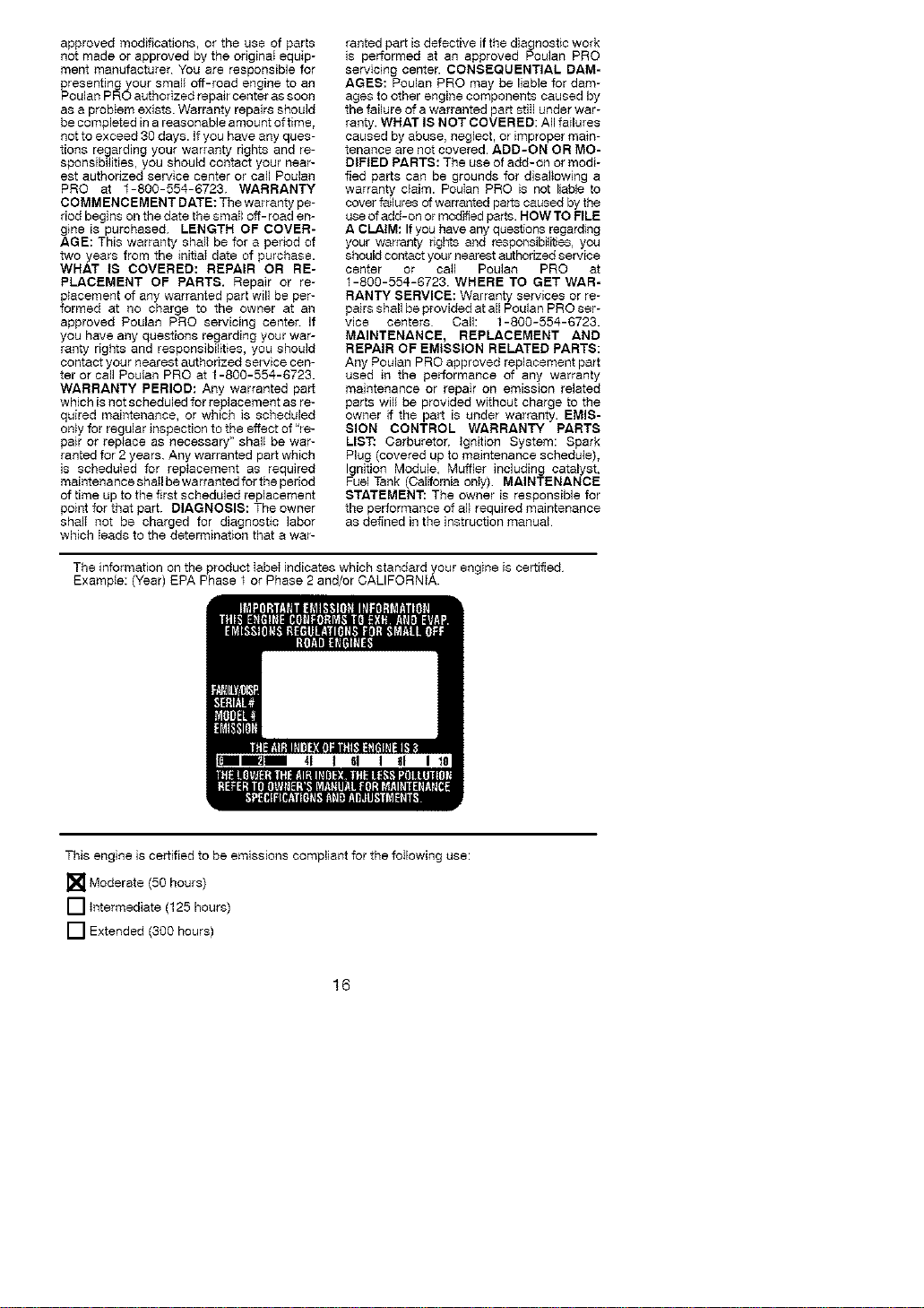
The information on the product label indicates which standard your engine is certified
Example: (Year) EPA Phase f or Phase 2 and/or CALIFORNIA.
This engine is certified to be emissions compliant for the following use:
[]Moderate (50 hours)
[] Intermediate (125 hours)
[] Extended (300 hours)
16