Loading ...
Loading ...
Loading ...

GB
- 22 -
Caution!
Residual risks
Even if you use this electric power tool in
accordance with instructions, certain resi-
dual risks cannot be rules out. The following
hazards may arise in connection with the
equipment’s construction and layout:
1. Damage to hearing if no suitable ear protec-
tion is used.
2. Health damage caused by hand-arm vib-
rations if the equipment is used over a pro-
longed period or is not properly guided and
maintained.
Danger!
The electric power tool generates an electro-
magnetic fi eld during operation. Under certain
circumstances this fi eld may actively or passively
impede medical implants. To reduce the risk of
serious or fatal injuries, we recommend persons
with medical implants to consult their doctor and
the manufacturer of the medical implant prior to
using the equipment.
5. Before starting the equipment
Warning!
Always pull out the safety plug before performing
any adjusting, repair, maintenance or cleaning
work on the equipment.
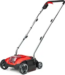
The scarifi er is delivered unassembled. The com-
plete push bar must be assembled and mounted
before using the scarifi er.
Follow the operating instructions step-by-step
and use the pictures provided as a visual guide to
easily assemble the machine.
Important! Required assembly parts (screws,
cable guides, etc.) or functional parts (e.g. plugs,
wrenches, etc.) can be found in the shaped parts
of the packaging or on the equipment.
Fitting the push bar holders and cable clips
(Fig. 3 - 6)
1. Screw the left push bar holder (Item 5) secu-
rely on the housing. Make sure that the em-
bossing (Fig. 2 / Item A) faces inwards. Then
screw on the right-hand push bar holder (Fig.
2 / Item 12) securely.
2. Use the fastening screws (Item 14) and the
wing nuts (Item 13) to screw one tube (Item
4) securely on each push bar holder (Item 5 /
12).
3. Screw the upper push bar (Item 3) on each
tube (Item 4). Use the push bar fastening
screws (Item 14) and the wing nuts (Item 13)
similarly for this purpose.
4. Fasten the power cable to the push bar tubes
using the supplied cable clips (Item 11). Make
sure that the cable and cable clips do not
obstruct the push bar when it is fl ipped over
(see section 8).
Important! There are 2 assembly holes so that
the height of the push bar can be adjusted to spe-
cifi c user requirements at any time. Use the hole
which is best suited for you, making sure that you
use the same hole on both sides.
Please ensure that the ejector fl ap can be opened
and closed easily!
Fitting the optional catch basket
(see Fig. 7-8)
The basic version of the equipment does not in-
clude a catch basket. This is available separately
(Art. No. 34.059.40).
•
To hang the grass basket on the scarifier you
must lift the ejector flap (Item 10) with one
hand and with the other hand take hold of the
grass bag by the handle and hook it onto the
scarifier from above.
Danger!
Before you ever hook the grass basket to the sca-
rifi er you must ensure that the motor is switched
off and the cutting unit is not rotating.
Adjusting the working depth (see Fig. 9)
The scarifi er depth is adjusted at the two front
wheels using the adjustment mechanism. For this,
pull out the adjusting screw and turn the wheel to
the left or right into one of the available positions
(0/I/II/III).
The scarifi er depth must always be identically set
on both sides!
0 = drive/transport position
I = scarifi er depth 2 mm
II = scarifi er depth 4 mm
III = scarifi er depth 6 mm
Anl_GC_SC_18_28_Li_Solo_SPK13.indb 22Anl_GC_SC_18_28_Li_Solo_SPK13.indb 22 07.09.2021 16:13:1307.09.2021 16:13:13
Loading ...
Loading ...
Loading ...
