Loading ...
Loading ...
Loading ...
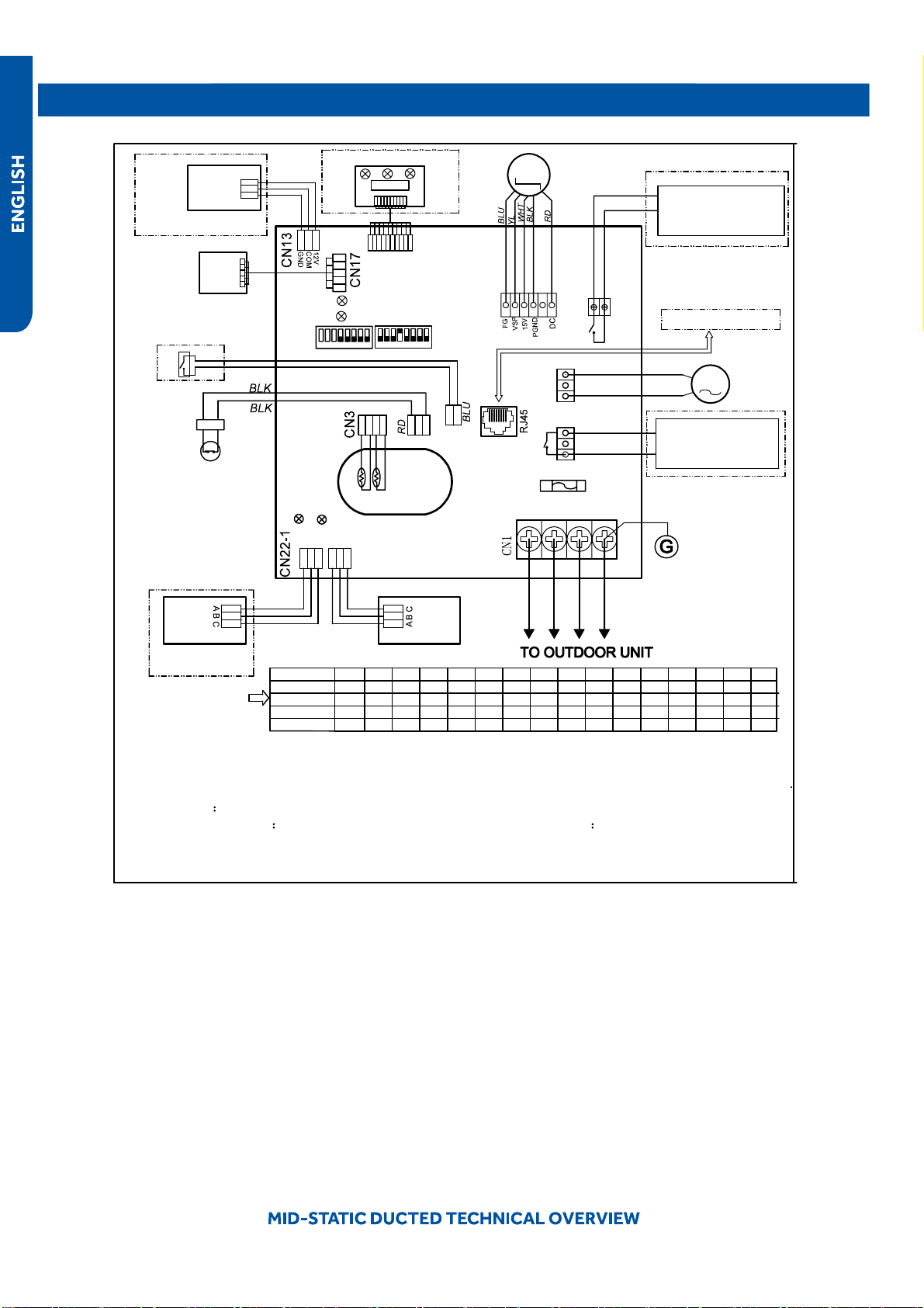
Wiring Diagram
FRELAY FOR FRESH AIR
●
MOTOR(dry Contact
,rating-230VAC,3A) /E.A.0
FUSE
T250V 5A
1(L1)
G
AC PUMP
MOTOR
DC FAN
MOTOR
A B
C
A B
C
Tp
Tr
CN16
ROOM CARD
FLOAT SWITCH
ON ON
YCJ-A002
INFRARED SIGNAL RECEIVER
TO RJ 45 device
CN22
LED2
LED1
SW01
SW03
CN21
CN6
CN20
LED3
LED4
Y/G
YL
YL
CN19
CN9
CN10
REMOTE
CENTRAL
CONTROL
ADAPTOR
2(L2) 3
NOTE:
1.Dashed parts are optional.
2.Please refer to service manual to get details of the DIP switches definition .
3.Do not change the DIP switches setting without technical support.
4.Get details from trouble shooting list about LED indication.
5.Abbreviation
●
RD -red, W -withe, BLK -black,BLU-blue,GRN-green,YL-yellow,Y/G -yellow/green
,
E.A.O:
external alarm output,Tr
indoor unit ambient(room) temperature sensor,Tp indoor unit pipe(coil)
temperature sensor.
6.The port CN4&CN10are dry contact output port for particular use,do not connect other device without
technical person suppo
●
rt.
M
M
WIRED
CONTROLLER
WIRED
CONTROLLER
1 2 3
4 5
6
7
8
1 2 3
4 5
6
7
8
CN4
P1 P2
RELAY FOR AUXILIARY
(dry contact port,contact
rating 230VAC,3A
BLU
GRN
BLU
W
BLK
W
W
Factory default setting
of the DIP switches
SW1-1 SW1-2 SW1-3 SW1-4 SW1-5 SW1-6 SW1-7 SW1-8 SW3-1 SW3-2 SW3-3 SW3-4 SW3-5 SW3-6 SW3-7 SW3-8
USYM
09UCDSA1
USYM
12UCDSA1
USYM
18UCDSA1
USYM
24UCDSA1
MODEL
OFF OFF OFF OFF OFF OFF OFF OFF OFF OFF OFF OFF OFF OFF OFF
ON
12V
COM
GND
W
W
WiFi MODULE
W
ON OFF OFF OFF OFF OFF OFF OFF OFF OFF OFF OFF OFF OFF OFF
ON
OFF OFF OFF OFF OFF OFF OFF OFF OFF OFF OFF OFF OFFOFF ON
ON ON
OFF OFF OFF OFF OFF OFF OFF OFF OFF OFF OFF OFF OFF
ON
ON
0151539442
●
PAGE 49
Loading ...
Loading ...
Loading ...