Loading ...
Loading ...
Loading ...
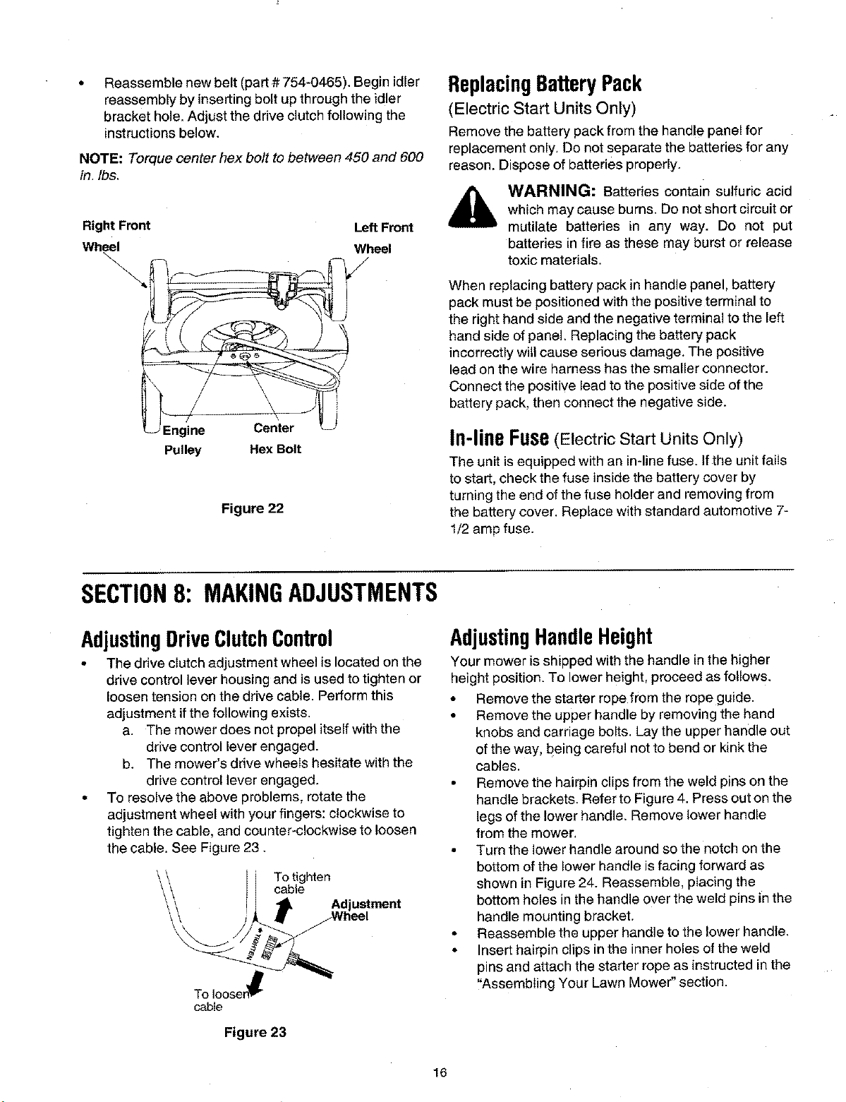
Reassemble new belt (part # 754-0465). Begin idler
reassembly by inserting bolt up through the idler
bracket hole. Adjust the drive clutch following the
instructions below.
NOTE" Torque center hex bolt to between 450 and 600
in. Ibs,
Right Front Left Front
Wheel Wheel
\
Engine Center
Pulley Hex Bolt
Figure 22
ReplacingBatteryPack
(Electric Start Units Only)
Remove the battery pack from the handle panel for
replacement only, Do not separate the batteries for any
reason. Dispose of batteries properly.
WARNING: Batteries contain sulfuric acid
which may cause burns. Do not short circuit or
mutilate batteries in any way. Do not put
batteries in fire as these may burst or release
toxic materials.
When replacing battery pack in handle panel, battery
pack must be positionedwith the positive terminal to
the right hand side and the negative terminal to the left
hand side of panel, Replacing the battery pack
incorrectly will cause serious damage. The positive
lead on the wire harness has the smaller connector.
Connect the positive lead to the positive side of the
battery pack, then connect the negative side.
In-lineFuse(Electric Start Units Only)
The unit is equipped with an in-line fuse. If the unit fails
to start, check the fuse inside the battery cover by
turning the end of the fuse holder and removing from
the battery cover. Replace with standard automotive 7-
1/2 amp fuse.
SECTION8: MAKINGADJUSTMENTS
AdjustingDriveClutchControl
• The drive clutch adjustment wheel is located on the
drive control lever housing and is used to tighten or
loosen tension on the drive cable. Perform this
adjustment if the following exists.
a. The mower does not propel itself with the
drive control lever engaged.
b. The mower's drive wheels hesitate with the
drive control lever engaged.
• To resolvethe above problems, rotate the
adjustment wheel with your fingers: clockwise to
tighten the cable, and counter-clockwise to loosen
the cable. See Figure 23.
To tighten
cable
To Iooser_
cable
Figure 23
AdjustingHandleHeight
Your mower isshipped with the handle in the higher
height position. To lower height, proceed as follows.
• Remove the starter rope from the rope guide.
• Remove the upper handle by removing the hand
knobs and carriage bolts. Lay the upper handle out
of the way, being careful net to bend or kink the
cables.
• Remove the hairpin clips from the weld pins on the
handle brackets. Refer to Figure 4. Press out on the
legs of the lower handle. Remove lower handle
from the mower,
• Turn the lower handle around so the notch on the
bottom of the lower handle is facing forward as
shown in Figure 24. Reassemble, placing the
bottom holes in the handle over the weld pins in the
handle mounting bracket.
• Reassemble the upper handle to the lower handle,
• Insert hairpin clips in the inner holes of the weld
pins and attach the starter rope as instructed in the
"Assembling Your Lawn Mower" section.
16
Loading ...
Loading ...
Loading ...