Loading ...
Loading ...
Loading ...
• Remove the two bolts and lock nuts from the blade
assembly,
• Remove the blade from blade adapter and pulley.
To ReplaceBlade:
• Before reinstalling the blade-pulley assembly to the
unit, lubricate the engine crankshaft and the inner
surface of the blade adapter with light oil.
• Also lubricate the bolt holes, bolt and the inner
surface of the nuts.
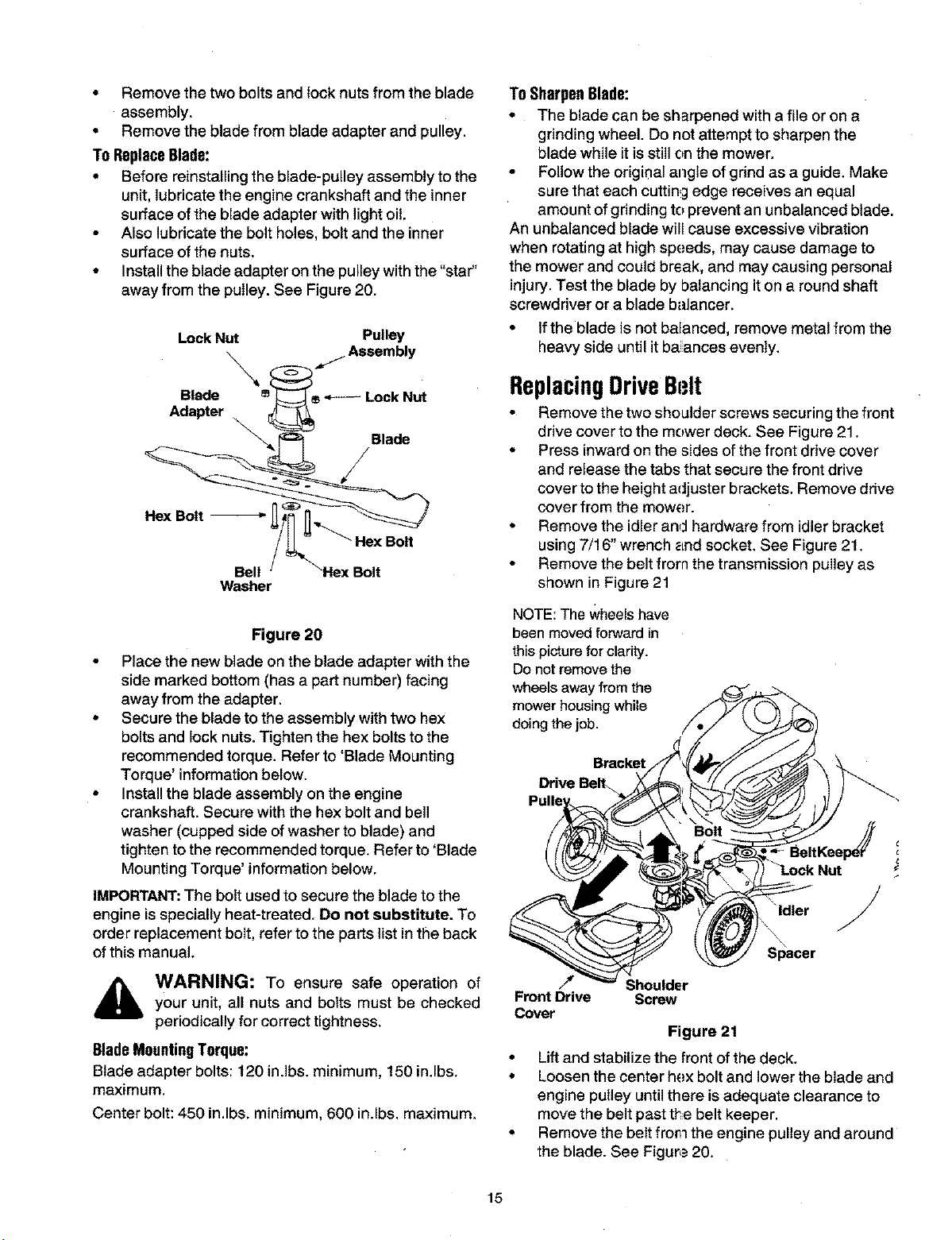
• Install the blade adapter on the pulley with the "star"
away from the pulley. See Figure 20.
Lock Nut Pulley
Washer
Figure 20
• Place the new blade on the blade adapter with the
side marked bottom (has a part number) facing
away from the adapter.
• Secure the blade to the assembly with two hex
bolts and lock nuts. Tighten the hex bolts to the
recommended torque. Refer to 'Blade Mounting
Torque' information below.
• Install the blade assembly on the engine
crankshaft. Secure with the hex bolt and bell
washer (cupped side of washer to blade) and
tighten to the recommended torque. Refer to 'Blade
Mounting Torque' information below,
IMPORTANT:The bolt used to secure the blade to the
engine is specially heat-treated. Do not substitute. To
order replacement bolt, refer to the parts list in the back
of this manual.
_ WARNING: To ensure safe operation ofyour unit, all nuts and bolts must be checked
periodically for correct tightness.
BladeMountingTorque:
Blade adapter bolts: 120 in.lbs, minimum, 150 in.lbs.
maximum,
Center bolt: 450 in.lbs, minimum, 600 in.lbs, maximum,
To SharpenBlade:
• The blade can be sharpened with a file or on a
grinding wheel. Do not attempt to sharpen the
blade while it is still on the mower.
• Follow the origir_al angle of grind as a guide. Make
sure that each cutting edge receives an equal
amount of grinding to prevent an unbalanced blade.
An unbalanced blade will cause excessive vibration
when rotating at high speeds, may cause damage to
the mower and could break, and may causing personal
injury. Test the blade by balancing it on a round shaft
screwdriver or a blade balancer.
• Ifthe blade is not balanced, remove metal from the
heavy side until it ba ances evenly.
ReplacingDriveBt;It
• Remove the two shoulder screws securing the front
drive cover to the mower deck. See Figure 21.
• Press inward on the sides of the front drive cover
and release the tabs that secure the front drive
cover to the height adjuster brackets. Remove drive
cover from the mower.
• Remove the idler and hardware from idler bracket
using 7/16" wrench _=ndsocket. See Figure 21.
• Remove the belt from the transmission pulley as
shown in Figure 21
NOTE:The Wheelshave
been moved forward in
this picturefor clarity.
Donot remove the
wheels away from the
mower housing while
doing the job.
Bracket
Drive BeE
"_ldler /
\
Sl_acer
/_ Shoulder
Front Drive Screw
Cover
Figure 21
• Lift and stabilize the front of the deck.
• Loosen the center hex bolt and lower the blade and
engine pulley until there isadequate clearance to
move the belt past the belt keeper,
• Remove the belt from the engine pulley and around
the blade. See Figure 20.
15
Loading ...
Loading ...
Loading ...