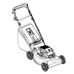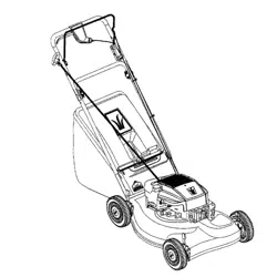

Operator's Manual
21" Rear-Discharge
Lawn Mower
Model Series
440 Thru E459
IMPORTANT: Read safety rules and instructions carefully before operating equipment.
"Warning: This unit is equipped with an intemaI combustion engine and should not be used on or near any unimproved forest-
covered, brush-covered or grass-covered land unless the engine's exhaust system is equipped with a spark arrester meeting
applicable local or state laws (if any). If a spark arrester is used, it should be maintained in effective working order by the operator.
In the State of California the above is required by law (Section 4442 of the California Public Resources C,ode). Other states may have
similar laws. Federal laws apply on federal lands. A spark arrester for the muffler is available through your nearest engine authorized
service dealer or contact the service department, P,O. Box 368022 Cleveland, Ohio 44136-9722.
MTD PRODUCTS INC. P.O. BOX 368022 CLEVELAND, OHIO 44136-9722
ECO # 2844
PRINTED IN U.S.A. FORM NO. 770-10134B
(11/2000)

TABLEOFCONTENTS
Content Page
Important Safe Operation Practices ................................................................... 3
Slope Gauge ...................................................................................................... 6
Assembling Your Lawn Mower ........................................................................... 7
Know Your Lawn Mower .................................................................................... 11
Operating Your Lawn Mower ............................................................................. 12
Maintaining Your Lawn Mower ........................................................................... 13
Service ............................................................................................................... 14
Making Adjustments .......................................................................................... 16
Off- Season Storage .......................................................................................... 17
Troubleshooting ................................................................................................. 18
Parts List ............................................................................................... _............ 19
FINDINGMODELNUMBER
This Operator's Manual is an important part of your new Lawn Mower. It will help you assemble, prepare
and maintain the unit for best performance. Please read and understand what it says.
Before you start assembling your new equipment, please locate the model plate on the
equipment and copy the information from it inthe space provided below. The information on
the model plate is very important if you need help from our Customer Support Department or
an authorized dealer.
You can locate the model number by standing behind the unit in the operating position and looking
down at the rear of the deck. A sample model plate is explained below. For future reference, please
copy the model number and the serial number of the equipment in the space below.
r
(Model Number)
(Serial Number)
MTD / .TDP.ooucTs,NC
CLEVELAND, OHIO 44136
111/ ,,
Copy the model number here:
Copy the serial number here:
CALLINGCUSTOMERSUPPORT
If you have difficulty assembling this product or have any questions regarding the controls, operation or
maintenance of this unit, please ca]] the Customer Support Department.
Call 1- (330) 220-4MTD (4683) or 1- (800)-800-7310 to reach a Customer Support
representative. Please have your unit's model number and serial number ready when you
call. See previous section to locate this information. You will be asked to enter the serial
number in order to process your call.
SECTION1: IMPORTANTSAFEOPERATIONPRACTICES
WARNING: This symbol points out important safety instructions which, ifnot followed, could endanger
the personal safety and/or property of yourself and others. Read and follow all instructions in this manual
before attempting to operate this machine. Failure to comply with these instructions may result in personal
injury. When you see this symbol--HEED ITS WARNING.
WARNING: Engine exhaust, some of its constituents, and certain vehicle components contain or emit
chemicals known to State of California to cause cancer and birth defects or other reproductive harm.
WARNING: This machine was built to be operated according to the rules for safe operation in this manual. As with
any type of power equipment, carelessness or error on the part of the operator can result in serious injury. This
machine is capable of amputating hands and feet and throwing objects. Failure to observe the following safety
instructions could result in serious injury or death.
GeneralOperation
1. Read this operator's manual carefully in its entirety
before attempting to assemble this machine. Read,
understand, and follow all instructions on the machine
and in the manual(s) before operation, Be completely
familiar with the controls and the proper use of this
machine before operating it. Keep this manual in a safe
place for future and regular reference and for ordering
replacement parts.
2. This machine is a precision piece of power equipment,
not a plaything. Therefore, exercise extreme caution at all
times. Your unithas been designed to perform one job: to
mow grass. Do not use it for any other purpose.
3. Never allow children under 14 years old to operate this
machine. Children 14 years old and over should read and
understand the operation instructions and safety rules in
this manual and should be trained and supervised by a
parent. Only responsible individuals who are familiar with
these safe operation rules should use this machine.
4. Thoroughly inspect the area where the equipment isto
be used. Remove all stones, sticks, wire, bones, toys and
other foreign objects which could be tripped over or
picked up and thrown by the blade. Thrown objects can
cause serious personal injury. Plan your mowing pattern
to avoid discharge of material toward roads, sidewalks,
bystanders and the like. Also, avoid discharging material
against a wall or obstruction which may cause discharged
material to ricochet back toward the operator.
5. To help avoid blade contact or a thrown object injury, stay
in the operator zone behind the handles and keep
bystanders, helpers, children and pets at least 75 feet
from the machine white it is in operation. Stop machine if
anyone enters the area.
6._ Always wear safety glasses or safety goggles during
operation and while performing an adjustment or repair to
protect your eyes. Thrown objects which ricochet can
cause serious injury to the eyes.
7. Wear sturdy, rough-soled work shoes and close-fitting
slacks and shirts. Shirts and pants that cover the arms
and legs and steel-toed shoes are recommended. Never
operate this machine in bare feet, sandals, slippery or
light weight (e.g, canvas) shoes.
8. Do not put hands or feet near rotating parts or under the
cuffing deck. Contact with the blade can amputate hands
and feet,
9. A missing or damaged discharge cover can cause blade
contact or thrown object injuries.
10. Many injuries occur as _result of the mower being puffed
over the foot during a f_LIIcaused by slipping or tripping.
Do not hold on to the mswer if you are falling; release the
handle immediately.
11. Never pull the mower back toward you while you are
walking. Ifyou must baok the mower away from a wall or
obstruction first look down and behind to avoid tdpping
and then follow these s!eps:
a. Step back from ':he mower to fully extend your
arms.
b. Be sure you are well balanced with sure footing.
c. Pull the mower back slowly, no more than half way
toward you.
d. Repeat these steps as needed.
12. Do not operate the mo\ver while under the influenoe of
alcohol or drugs.
13. Do not engage the self-propelled mechanism on units
so equipped while starting engine.
14, The blade control handle is a safety device. Never
attempt to bypass its operation. Doing so makes the
safety device inoperative and may result in personal
injurythrough contact with the rotating blade. The blade
control handle must operate easily in both directions and
automatically return to the disengaged position when
released.
15. Never operate the mower in wet grass. Always be sure of
your footing. A slip and fall can cause serious personal
injury. Ifyou feel you are losing your footing, release the
blade control handle immediately and the blade will stop
rotating within three se_nds.
16. Mow in daylight or good artificial light.Walk, never run.
17. Stop the blade when crossing gravel drives, walkways
or roads.
18. ifthe equipment should statt to vibrate abnormally, stop
the engine and check immediately for the cause.
Vibration is generally a warning of trouble.
19. Shut the engine off and wait until the blade comes to a
complete stop before removing the grass catcher or
unclogging the chute. "_he cutting blade continues to
rotate for a few seconds after the engine is shut off.
Never place any part of the body in the blade area until
you are sure the blade has stopped rotating.
20. Never operate mower without proper trail shield,
discharge cover, grass catcher, blade control handle or
3
other safety protective devices in place and working.
Never operate mower with damaged safety devices.
Failure to do so, can result in personal injury.
21. Muffler and engine become hot and can cause a burn. Do
not touch.
22. Only use parts and accessories made for this machine by
the original equipment manufacturer (O.EM). Failure to
do so can result in personal injury.
23. If situations occur which are not covered in this manual,
use care and good judgment. Contact your dealer for
assistance. Telephone 1-800-800-7310 for the name of
your nearest dealer.
SlopeOperation
Slopes are a major factor related to slip and fall accidents
which can result in severe injury. Operation on slopes
requires extra caution. If you feel uneasy on a slope, do not
mow it. Before operating this unit on a slope or hilly area, use
the slope gauge on page 6 to measure slopes. If the slope is
greater than 15 degrees, do not mow it.
Do:
1. Mow across the face of slopes; never up and down.
Exercise extreme caution when changing direction on
slopes.
2. Watch for holes, ruts, rocks, hidden objects, or bumps
which can cause you to slip or trip, Tall grass can hide
obstacles.
3. Always be sure of your footing. A slip and fall can cause
serious personal injury. Ifyou feel you are losing your
balance, release the blade control handle immediately,
and the blade will stop rotating within 3 seconds.
DoNot:
1. Do not mow near drop-offs, ditches or embankments,
you could lose your footing or balance.
2. Do not mow slopes greater than 15 degrees as shown on
the slope gauge.
3. Do not mow on wet grass. Unstable footing could cause
slipping.
Children
Tragic accidents can occur if the operator is not alert to the
presence of children. Children are often attracted to the
mower and the mowing activity. They do not understand the
dangers. Never assume that children will remain where you
last saw them.
1. Keep children out of the mowing area and under the
watchful care of a responsible adult other than the
operator,
2. Be alert and turn mower off if a child enters the area.
3. Before and while moving backwards, look behind and
down for small children.
4. Use extreme care when approaching blind corners,
doorways, shrubs, trees, or other objects that may
obscure your vision of a chiZdwho may run into the
mower.
5. Keep children away from hot or running engines. They
can suffer burns from a hot muffler.
6. Never allow children under 14 years old to operate a
power mower. Children 14 years old and over should
read and understand the operation instructions and
safety rules in this manual and should be trained and
supervised by a parent,
Service
Safe Handlingof Gasoline:
1. To avoid personal injury or property damage use extreme
care in handling gasoline. Gasoline is extremely
flammable and the vapors are explosive Serious
personal injury can occur when gasoline is spi!led on
yourself or your clothes which can ignite.
2. Wash your skin and change clothes immediately.
3. Use only an approved gasoline container.
4. Never fill containers inside a vehicle or on a truck or
trailer bed with a plastic liner. Always place containers on
the ground away from your vehicle before filling.
5. If possible, remove gas-powered equipment from the
truck or trailer and refuel it on the ground. If this is not
possible, then refuel such equipment on atrailer with a
portable container, rather than from a gasoline dispenser
nozzle.
6. Keep the nozzle in contact with the rim of the fuel tank or
container opening at all times until fueling is complete. Do
not use a nozzle lock-open device.
7. Extinguish all cigarettes, cigars, pipes and other sources
of ignition.
8. Never fuel machine indoors because flammable vapors
will accumulate in the area.
9. Never remove gas cap or add fuel while the engine is hot
or running. Allow engine to cool at least two minutes
before refueling.
10. Neverover fillfueltank. FilltanktonomorethanY2inch
below bottom of filler neck to provide space for fuel
expansion.
11. Replace gasoline cap and tighten securely.
12. If gasoline is spilled, wipe it off the engine and
equipment. Move unit to another area. Wait 5 minutes
before starting the engine.
13. Never store the machine or fuel container inside where
there is an open flame, spark or pilot light as on a water
heater, space heater, furnace, clothes dryer or other gas
appliances.
14. To reduce fire hazard, keep mower free of grass, leaves,
or other debris build-up. Clean up oil or fuel spillage and
remove any fuel soaked debris.
15. Allow a mower to cool at least 5 minutes before storing.
GeneralService:
1. Never run an engine indoors or in a poorly ventilated
area. Engine exhaust contains carbon monoxide, an
odorless and deadly gas.
2. Before cleaning, repairing, or inspecting, make certain
the blade and all moving parts have stopped. Disconnect
the spark plug wire and ground against the engine to
prevent unintended starting.
3. Check the blade and engine mounting bolts at frequent
intervals for proper tightness. Also, visually inspect blade
for damage (e.g., bent, cracked, worn) Replace blade
with the original equipment manufacture's (O,E.M.) blade
only, listed in this manual "Use of parts which do not
meettheoriginalequipmentspecificationsmayleadto
improperperformanceandcompromisesafety!"
4. Mowerbladesaresharpandcancut.Wrapthebladeor
weargloves,anduseextra caution when servicing them.
5. Keep al! nuts, bolts, and screws tight to be sure the
equipment is in safe working condition;
6. Never tamper with safety devices. Checktheir proper
operation regularly.
7. After striking a foreign object, stop the engine, disconnect
the spark plug wire and ground against the engine.
Thoroughly inspect the mower for any damage. Repair
the damage before starting and operating the mower.
8. Never attempt to make awheel or cutting height
adjustment while the engine is running,
9, Grass catcher components, discharge cover, and trail
shield are subject to wear and damage which could
expose moving parts el' allow objects to be thrown. For
safety protection, frequently check components and
replace immediately with original equipment
manufacturer's (O.E.M,) parts only, listed in this manual.
"Use of parts which do not meet the original equipment
specifications may lead to improper performance and
compromise safety!"
10. Do not change the eng ne governor setting or overspeed
the engine. The governor controls the maximum safe
operating speed of the engine.
11. Maintain or replaos safety and instruction labels, as
necessary.
12. Observe proper disposal laws and regulations. Improper
disposal of fluids and materials can harm the
environment.
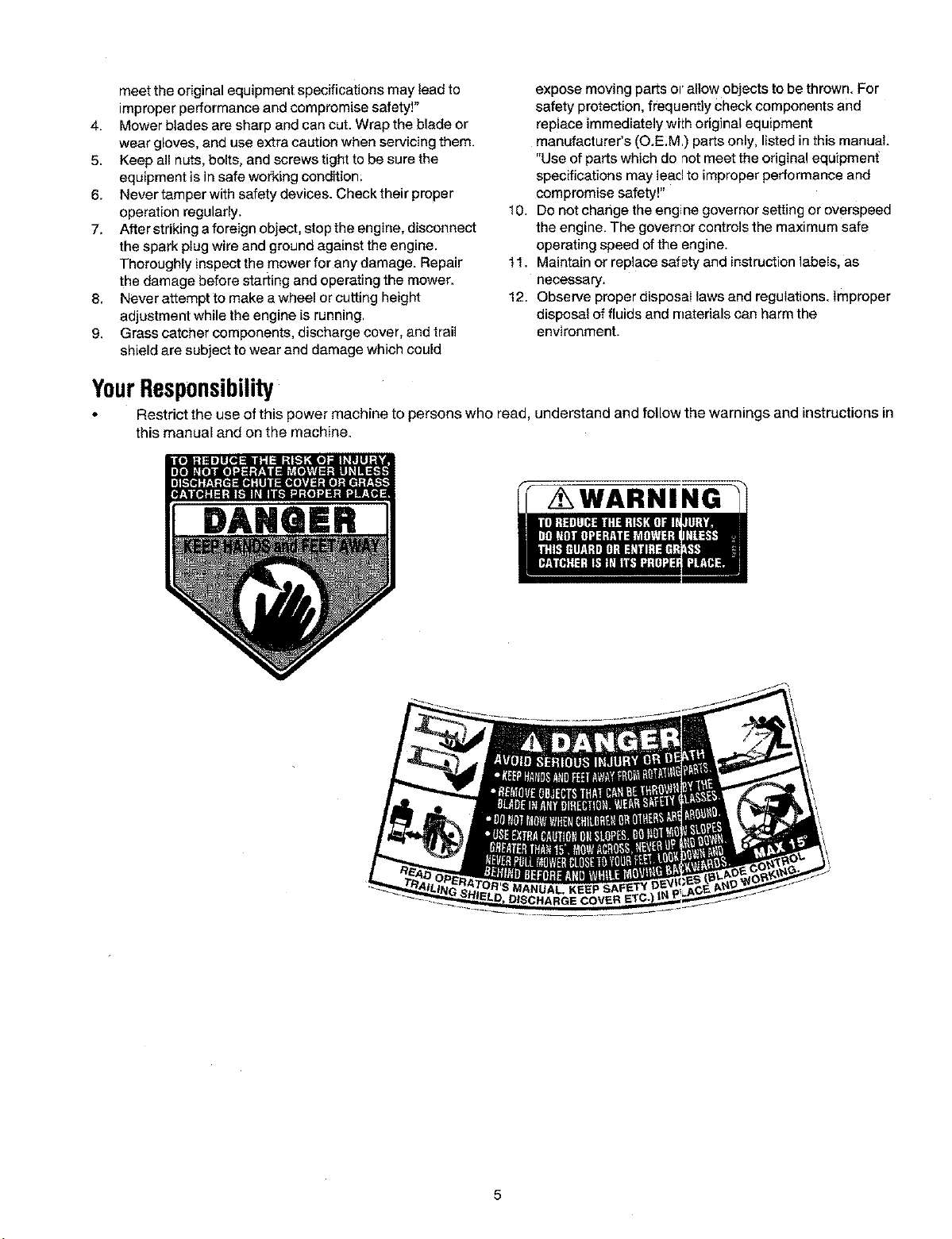
YourResponsibility
Restrict the use of this power machine to persons who read, understand and follow the warnings and instructions in
this manual and on the machine.
DANGER
/ WARNING
=,
==
.II
I
I
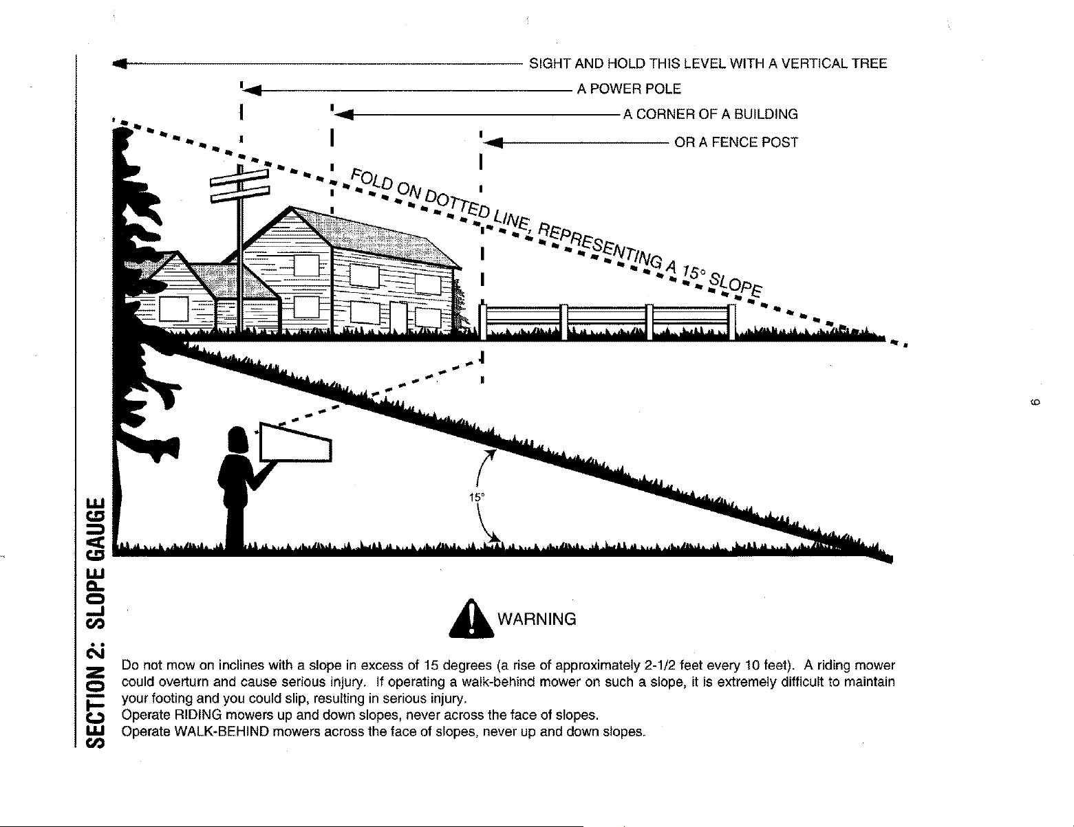
SIGHT AND HOLD THIS LEVEL WITH A VERTICAL TREE
A POWER POLE
A CORNER OF A BUILDING
OR A FENCE POST
Do not mow on inclines with a slope in excess of 15 degrees (a rise of approximately 2-1/2 feet every 10 feet). A riding mower
could overturn and cause serious injury, if operating a walk-behind mower on such a slope, it is extremely difficult to maintain
your footing and you could slip, resulting in serious injury.
Operate RIDING mowers up and down slopes, never across the face of slopes.
Operate WALK-BEHIND mowers across the face of slopes, never up and down slopes.
{.o
SECTION3: ASSEMBLINGYOURLAWNMOWER
RemovingUnitFromCarton
• Remove staples, break glue on top flaps or cut tape
at carton end and peel along top flap to open
carton.
• Remove loose parts ifincluded with unit (i.e.,
operator's manual, hardware pack etc.).
• Cut corners and lay carton down flat. Remove
packing matedaL
• Roll or slide unit out of carton. Check carton
thoroughly for loose parts.
NOTE: Make sure not to crimp the cables while
removing the loose parts or the entire unit from the
carton.
NOTE: Reference to right or left hand side of the mower
is observed from the operating position.
ToolsRequired
• Pair of Pliers
• Funnel
• Set of adjustable wrenches
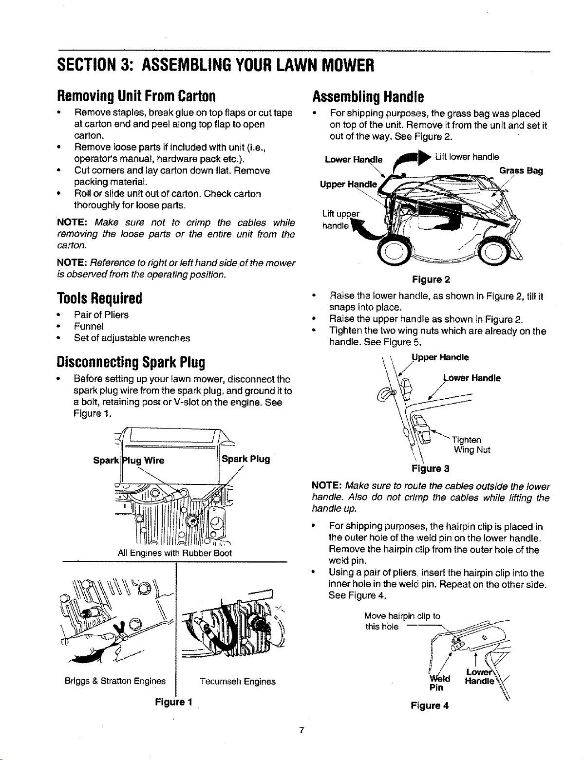
DisconnectingSparkPlug
• Before setting up your lawn mower, disconnect the
spark plug wire from the spark plug, and ground it to
a bolt, retaining post or V-slot on the engine. See
Figure 1.
t Iftltl tfjl/lt
All Engines with Rubber Boot
Spark Plug
,/
Briggs & Stratton Engines
Tecumseh Engines
Figure 1
AssemblingHandle
• For shipping purposes, the grass bag was placed
on top of the unit. Remove itfrom the unit and set it
out of the way. See Figure 2.
Lower Liftlower handle
Grass Bag
f
Upper
Lift
handl_
Figure 2
• Raise the lower handle, as shown in Figure 2, till it
snaps into place.
• Raise the upper handle as shown in Figure 2.
• Tighten the two wing nuts which are already on the
handle. See Figure 5.
_/U Pper HLotlwdle_Harldle
Figure 3
NOTE: Make sure to route the cables outside the lower
handle. Also do not crimp the cables while lifting the
handle up.
• For shipping purposes, the hairpin clip is placed in
the outer hole of the weld pin on the lower handle.
Remove the hairpin (:lip from the outer hole of the
weld pin.
° Using a pair of pliers insert the hairpin clip intothe
inner hole in the wels pin. Repeat on the other side.
See Figure 4.
Move hairpin _,lipto
this h01e
Weld Handle
Pin
Figure 4
7
Insert post of cable ties that are on lower handle
into the holes provided on the lower handle. The
holes may be on the inside or outside. Pull cable
ties tight and cut off the extra, See Figure 5 below,
Cable Tie
\
Poston
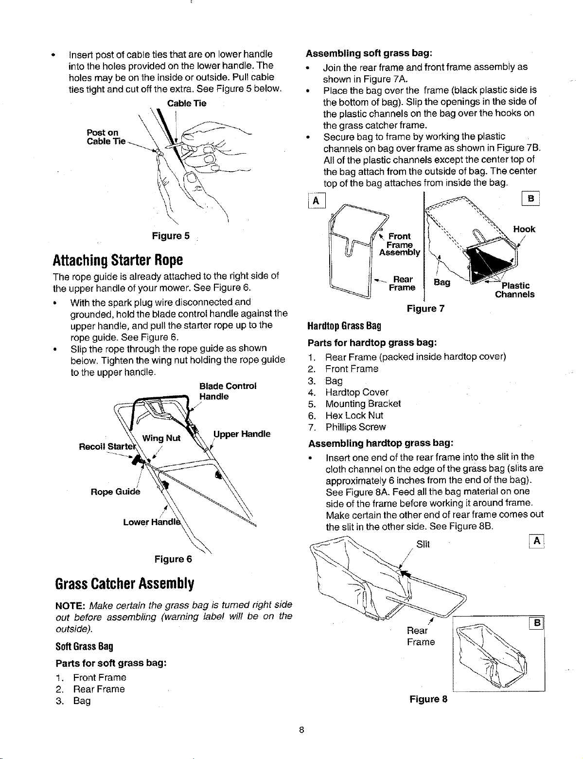
Assembling soft grass bag:
• Join the rear frame and front frame assembly as
shown in Figure 7A.
• Place the bag over the frame (black plastic side is
the bottom of bag). Slip the openings in the side of
the plastic channels on the bag over the hooks on
the grass catcher frame.
• Secure bag to frame by working the plastic
channets on bag over frame as shown in Figure 7B.
All of the plastic channels except the center top of
the bag attach from the outside of bag. The center
top of the bag attaches from inside the bag.
Figure 5
AttachingStarterRope
The rope guide is already attached to the right side of
the upper handle of your mower. See Figure 6,
• With the spark plug wire disconnected and
grounded, hold the blade control handle against the
upper handle, and pull the starter rope up to the
rope guide. See Figure 6.
• Slip the rope through the rope guide as shown
below, Tighten the wing nut holding the rope guide
to the upper handle.
BladeControl
Handle
Upper Handle
/
/
Rope Guide
/
Figure 6
GrassCatcherAssembly
NOTE: Make certain the grass bag is turned right side
out before assembling (warning label will be on the
outside).
SoftGrassBag
Parts for soft grass bag:
1. Front Frame
2. Rear Frame
3. Bag
Frame
Assembly
Hook
Rear
Frame
Plastic
Channels
Figure 7
HardtopGrassBag
Parts for hardtop grass bag:
1, Rear Frame (packed inside hardtop cover)
2. Front Frame
3. Bag
4. Hardtop Cover
5. Mounting Bracket
6. Hex LockNut
7. Phillips Screw
Assembling hardtop grass bag:
• insert one end of the rear frame into the slit in the
cloth channel on the edge of the grass bag (slits are
approximately 6 inches from the end of the bag).
See Figure 8A. Feed all the bag material on one
side of the frame before working it around frame.
Make certain the other end of rear frame comes out
the slit in the other side. See Figure 8B,
Slit
/
Rear []
Frame
Figure 8
8
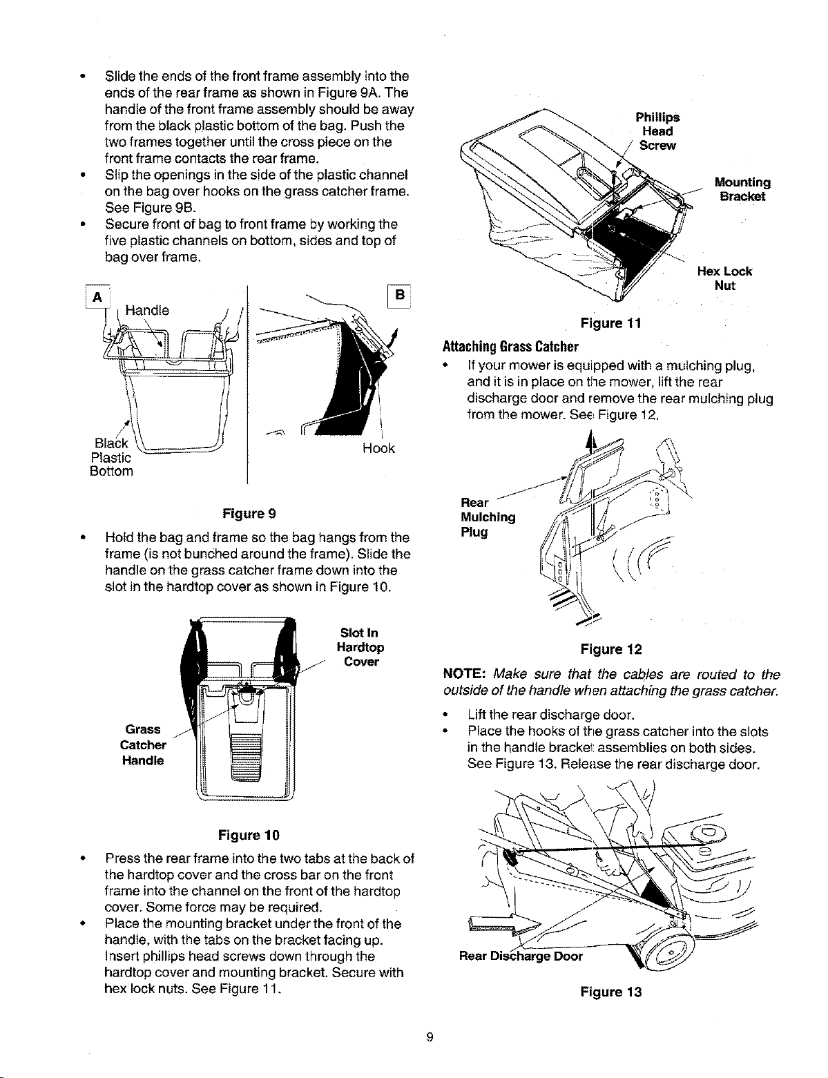
• Slide the ends of the front frame assembly into the
ends of the rear frame as shown in Figure 9A. The
handle of the front frame assembly should be away
from the black plastic bottom of the bag. Push the
two frames together until the cross piece on the
front frame contacts the rear frame.
• Slip the openings in the side of the plastic channel
on the bag over hooks on the grass catcher frame.
See Figure 9B.
• Secure front of bag to front frame by working the
five plastic channels on bottom, sides and top of
bag over frame.
A
Plastic
Bottom
Handle
L
Hook
Figure 9
Hold the bag and frame so the bag hangs from the
frame (is not bunched around the frame). Slide the
handle on the grass catcher frame down into the
slot in the hardtop cover as shown in Figure 10,
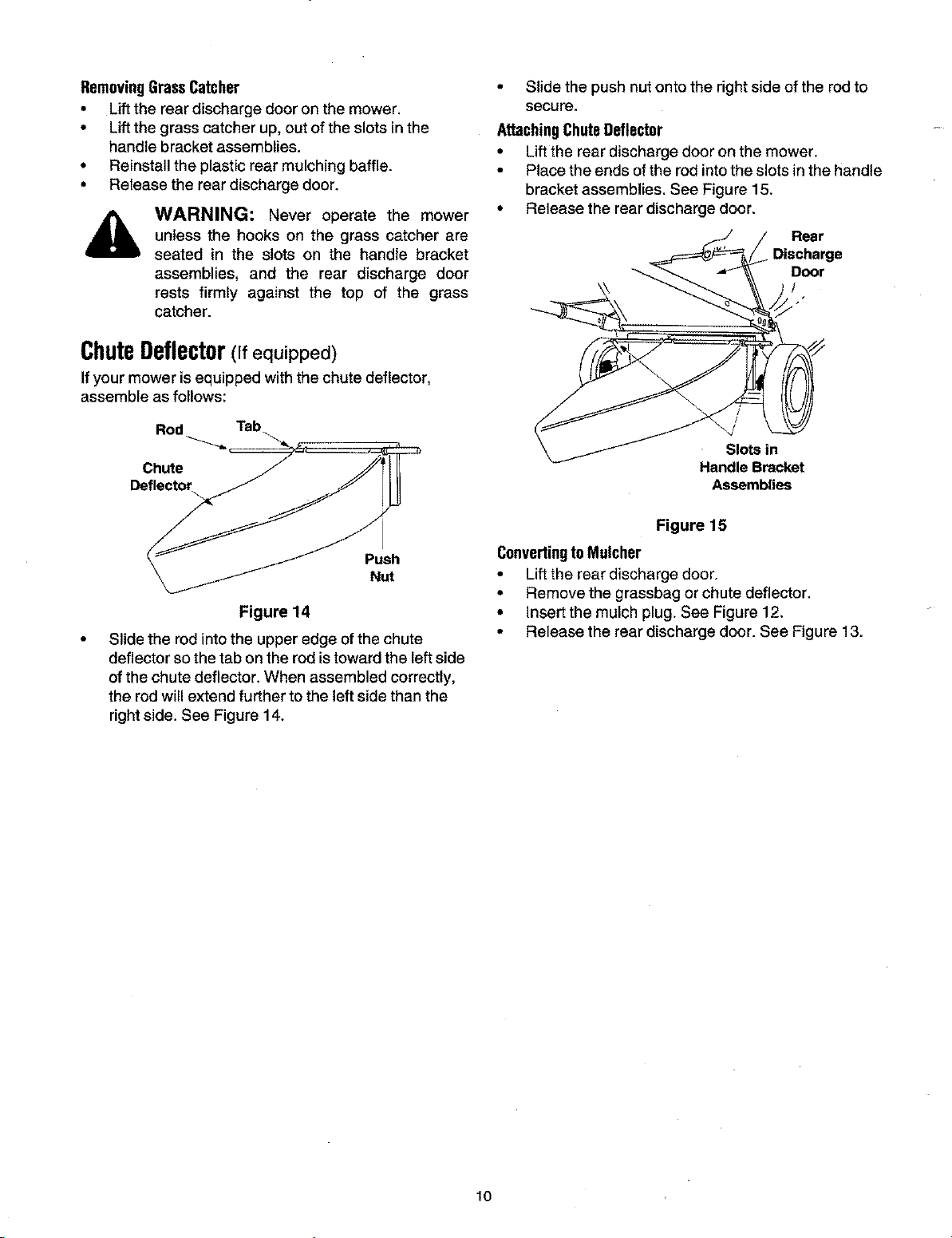
Phillips
Heed
Screw
Mounting
Bracket
Hex Lock
Nut
Figure 11
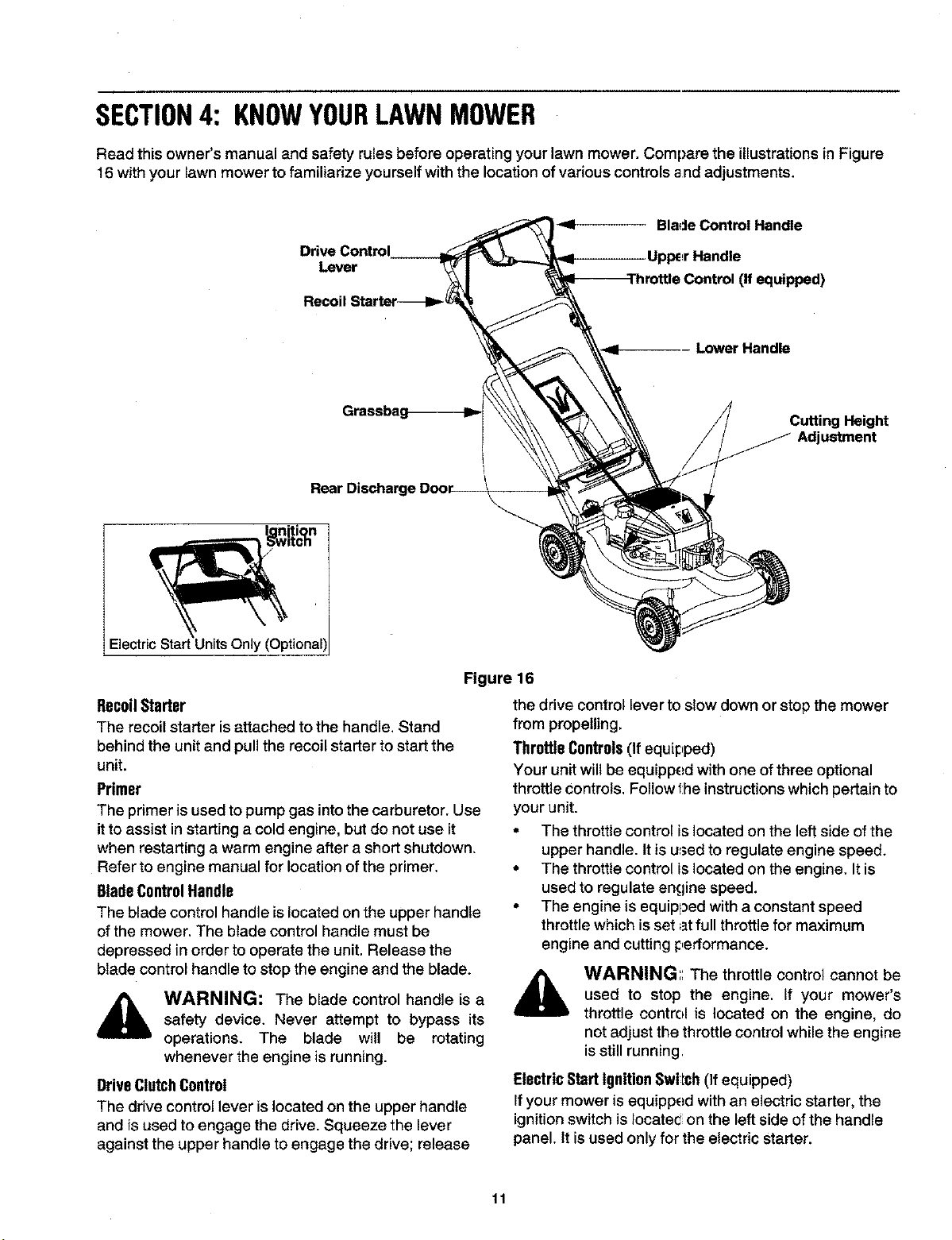
AttachingGrassCatcher
• If your mower is equipped with a muIching plug,
and it is in place on tl3emower, lift the rear
discharge door and remove the rear mulching plug
from the mower. See Figure 12.
Rear
Mulching
Plug
Grass
Catcher
Handle
Slot ln
Hardtop
Cover
Figure 12
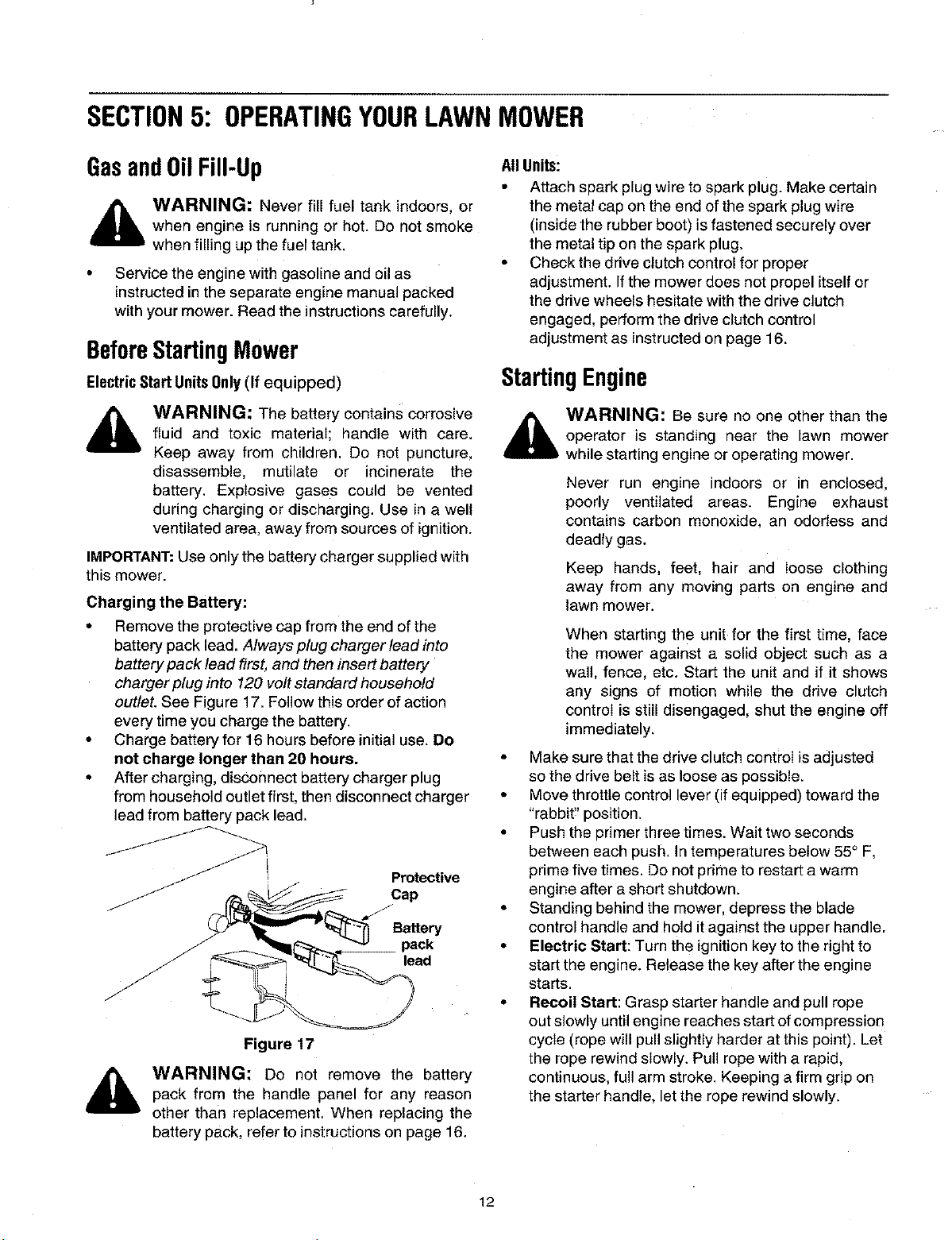
NOTE: Make sum that the cables are routed to the
outside of the handle when attaching the grass catcher.
• Lift the rear discharge door.
• Place the hooks of the grass catcher into the slots
in the handle bracket assemblies on both sides.
See Figure 13, Release the rear discharge door.
Figure 10
Press the rear frame intothe two tabs at the back of
the hardtop cover and the cross bar on the front
frame into the channel on the front of the hardtop
cover. Some force may be required.
Place the mounting bracket under the front of the
handle, with the tabs on the bracket facing up.
Insert phillips head screws down through the
hardtop cover and mounting bracket. Secure with
hex lock nuts. See Figure 11,
harge Door
Figure 13
RemovingGrassCatcher
• Liftthe rear discharge door on the mower.
,, Lift the grass catcher up, out of the slots in the
handle bracket assemblies.
• Reinstall the plastic rear mulching baffle.
• Release the rear discharge door.
WARNING: Never operate the mower
unless the hooks on the grass catcher are
seated in the slots on the handle bracket
assemblies, and the rear discharge door
rests firmly against the top of the grass
catcher.
• Slide the push nut onto the right side of the rod to
secure.
AttachingChuteDeflector
• Lift the rear discharge door on the mower.
• Place the ends of the rod into the slots in the handle
bracket assemblies. See Figure 15.
• Release the rear discharge door.
ChuteDeflector(Ifequipped)
If your mower is equipped with the chute deflector,
assemble as follows:
Rod Tab
Chute
Deflector
Rear
Discharge
Door
/
Slots in
Handle Bracket
Assemblies
Push
Nut
Figure 14
Slide the rod intothe upper edge of the chute
deflector sothe tab on the rod istoward the leftside
ofthe chute deflector. When assembled correctly,
the rod willextend further tothe left side than the
right side. See Figure 14.
Figure 15
Convertingto Mulcher
• Lift the rear discharge door.
• Remove the grassbag or chute deflector.
• Insert the mulch plug. See Figure 12.
• Release the rear discharge door. See Figure 13.
10
SECTION4: KNOWYOURLAWNMOWER
Read this owner's manual and safety rules before operating your lawn mower. Compare the illustrations in Figure
16 with your lawn mower to familiarize yourself with the location of various controls and adjustments.
Blade Control Handle
Drive Control Upper Handle
Lever
(If equipped)
Recoil Star ter---I_
Lower Handle
Rear Discharge DOOr
I_itiqn
itcn
\
Cutting Height
Adjustment
(Optional',
RecoilStarter
The recoil starter is attached to the handle. Stand
behind the unit and pull the recoil starter to start the
unit.
Primer
The primer is used to pump gas into the carburetor, Use
it to assist in starting a cold engine, but do not use it
when restarting a warm engine after a short shutdown.
Refer to engine manual for location of the primer.
BladeControlHandle
The blade control handle islocated on the upper handle
of the mower. The blade control handle must be
depressed in order to operate the unit. Release the
blade control handle to stop the engine and the blade.
WARNING: The blade control handle is a
safety device. Never attempt to bypass its
operations. The blade will be rotating
whenever the engine is running.
DriveClutchControl
The drive control lever islocated on the upper handle
and is used to engage the drive. Squeeze the lever
against the upper handle to engage the drive; release
Figure 16
the drive control lever to slow down or stop the mower
from propelling.
ThrottleControls(If equipped)
Your unitwillbe equipped with one ofthree optional
throttle controls, Followthe instructions which pertain to
your unit.
• The throttle control is located on the left side of the
upper handle. It is used to regulate engine speed.
• The throttle control is located on the engine. It is
used to regulate engine speed.
• The engine is equipped with a constant speed
throttle which is set at full throttle for maximum
engine and cutting performance.
WARNING:: The throttle control cannot be
used to stop the engine. If your mower's
throttle centrel is located on the engine, do
not adjust the throttle control while the engine
isstill running.
ElectricStartIgnition Swllch (If equipped)
If your mower is equipped with an electric starter, the
ignitionswitch is Iocatec_on the left side of the handle
panel. It isused only for the electric starter.
11
SECTION5: OPERATINGYOURLAWNMOWER
GasandOilFill-Up
,_ WARNING: Never fill fuel tank indoors, or
when engine is running or hot. Do not smoke
when filling up the fuel tank.
• Service the engine with gasoline and oil as
instructed in the separate engine manual packed
with your mower. Read the instructions carefully.
BeforeStartingMower
ElectricStart UnitsOnly(If equipped)
WARNING: The battery contains corrosive
fluid and toxic material; handle with care.
Keep away from children. Do not puncture,
disassemble, mutilate or incinerate the
battery. Explosive gases could be vented
during charging or discharging. Use in a well
ventilated area, away from sources of ignition.
IMPORTANT:Use only the battery charger supplied with
this mower.
Charging the Battery:
• Remove the protective cap from the end of the
battery pack lead. Always plug charger lead into
battery pack lead first, and then insert battery
charger plug into 120 volt standard household
outlet. See Figure 17. Follow this order of action
every time you charge the battery.
• Charge battery for 16 hours before initial use. Do
not charge longer than 20 hours.
• After charging, disconnect battery charger plug
from household outlet first, then disconnect charger
lead from battery pack lead.
Protective
Cap
Battery
__ pack
lead
Figure 17
WARNING: Do not remove the battery
pack from the handle panel for any reason
other than replacement. When replacing the
battery pack, refer to instructions on page 16.
AllUnits:
Attach spark plug wire to spark plug. Make certain
the metal cap on the end of the spark plug wire
(inside the rubber boot) is fastened securely over
the metal tip on the spark plug.
Check the drive clutch control for proper
adjustment. Ifthe mower does not propel itself or
the drive wheels hesitate with the drive clutch
engaged, perform the drive clutch control
adjustment as instructed on page 16.
StartingEngine
_ WARNING: Be sure no one other than the
operator is standing near the lawn mower
while starting engine or operating mower.
Never run engine indoors or in enclosed,
poorly ventilated areas. Engine exhaust
contains carbon monoxide, an odorless and
deadly gas.
Keep hands, feet, hair and loose clothing
away from any moving parts on engine and
lawn mower.
When starting the unit for the first time, face
the mower against a solid object such as a
wall, fence, etc. Start the unit and if it shows
any signs of motion while the drive clutch
control is still disengaged, shut the engine off
immediately.
• Make sure that the drive clutch control is adjusted
so the drive belt is as loose as possible.
• Move throttle control lever (if equipped) toward the
"rabbit_'position.
• Push the primer three times. Wait two seconds
between each push. In temperatures below 55° F,
prime five times. Do not prime to restart a warm
engine after a short shutdown.
• Standing behind the mower, depress the blade
control handle and hold it against the upper handle.
• Electric Start: Turn the ignition key to the right to
start the engine. Release the key after the engine
starts.
• Recoil Start: Grasp starter handle and pull rope
out slowly until engine reaches start of compression
cycle (rope will pull slightly harder at this point). Let
the rope rewind slowly. Pull rope with a rapid,
continuous, full arm stroke. Keeping a firm grip on
the starter handle, let the rope rewind slowly.
12
StoppingEngine
• Release blade control handle to stop the engine
and the blade.
• Disconnect spark plug wire and move away from
spark plug to prevent accidental starting.
UsingYourLawnMower
• Do not operate the mower without the mulching
cover, the grass catcher bag, or the discharge
chute properly installed.
• Be sure that the lawn is clear of stones, sticks, wire,
or other objects which could damage lawn mower
or engine. Such objects could be accidently thrown
by the mower in any direction and cause serious
personal injury to the operator and others.
• Forbestresults, donotcutwetgrassbecauseit
tends to stick to the underside of the mower,
preventing proper discharge of grass clippings,
poor mulching conditions, and could cause you to
slip and fall. New grass, thick grass, or wet grass
may require a narrower cut.
• For a healthy lawn, always cut off one-third or less
of the total length of the grass. Lawn should be
trimmed in fall as long as there is growth.
• Always operate your mower with the engine in the
full throttle (rabbit) position for the most effective
mulching or bagging of the cut grass.
WARNING: If you strike a foreign object,
stop the engine. Remove spark plug wire from
spark plug, thoroughly inspect the mower for
any damage. Repair the damage before
restarting and operating the mower. Extensive
vibration of the mower during operation is an
indication of damage. The unit should be
promptly inspected and repaired.
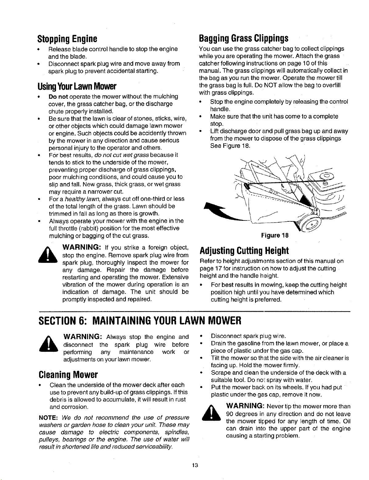
BaggingGrassClippings
You can use the grass catcher bag to collect clippings
while you are operating the mower. Attach the grass
catcher following instructions on page 10 of this
manual. The grass clippings will automatically collect in
the bag as you run the mower. Operate the mower till
the grass bag is full. Do NOT allow the bag to overfill
with grass clippings.
• Stop the engine completely by releasing the control
handle.
• Make sure that the unit has come to a complete
stop.
• Lift discharge door and pull grass bag up and away
from the mower to dispose of the grass clippings
See Figure 18.
Figure 18
AdjustingCuttingHeight
Refer to height adjustments section of this manual on
page 17 for instruction on how to adjust the cutting
height and the handle height.
• For best results in mowing, keep the cutting height
position high until you have determined which
cutting height is preferred.
SECTION6: MAINTAININGYOURLAWNMOWER
,_ WARNING: Always stop the engine and
disconnect the spark plug wire before
performing any maintenance work or
adjustments on your lawn mower.
CleaningMower
• Clean the underside of the mower deck after each
use to prevent any build-up of grass clippings. If this
debris is allowed to accumulate, it will result in rust
and corrosion.
NOTE: We do not recommend the use of pressure
washers or garden hose to clean your unit. These may
cause damage to electric components, spindles,
pulleys, bearings or the engine. The use of water will
result in shortened life and reduced serviceability_
A
• Disconnect spark plug wire.
• Drain the gasoline from the lawn mower, or place a
piece of plastic under the gas cap.
• Tilt the mower so that the side with the air cleaner is
facing up. Hold the mower firmly.
• Scrape and clean the underside of the deck with a
suitable tool. Do no".spray with water.
• Put the mower back on its wheels. Ifyou had put
plastic under the gas cap, remove it now.
WARNING:: Never tip the mower more than
90 degrees in any direction and do not leave
the mower tipped for any length of time. Oil
can drain into the upper part of the engine
causing a starting problem.
13
EngineMaintenance
A listof key maintenance jobs required for good
performance by the mower is given below. Follow the
accompanying engine manual for detailed list and
instructions.
• Change engine oil after the first two operating
hours and every 25 operating hours thereafter.
Check the oil level before starting the engine every
time.
• Service foam filter in the air cleaner every 25 hours
of use and replace the paper filter component every
100 hours. You may have to service the air filter
more frequently ifyou are operating the mower
under extremely dusty conditions.
• Clean engine periodically. Remo_e dirt and debris
with a cloth or brush.
• Clean the spark plug and reset the gap to.030" at
least once a season or every 50 hours of operation.
Spark plug replacement is recommended at the
start of each season.
• Inspect muffler periodically, and replace if
necessary. Damaged mufflers or spark arresters
can create a fire hazard. Make sure to avoid muffler
and surrounding areas while the mower engine is
hot because temperature of these areas of the
engine may exceed 150 °F.
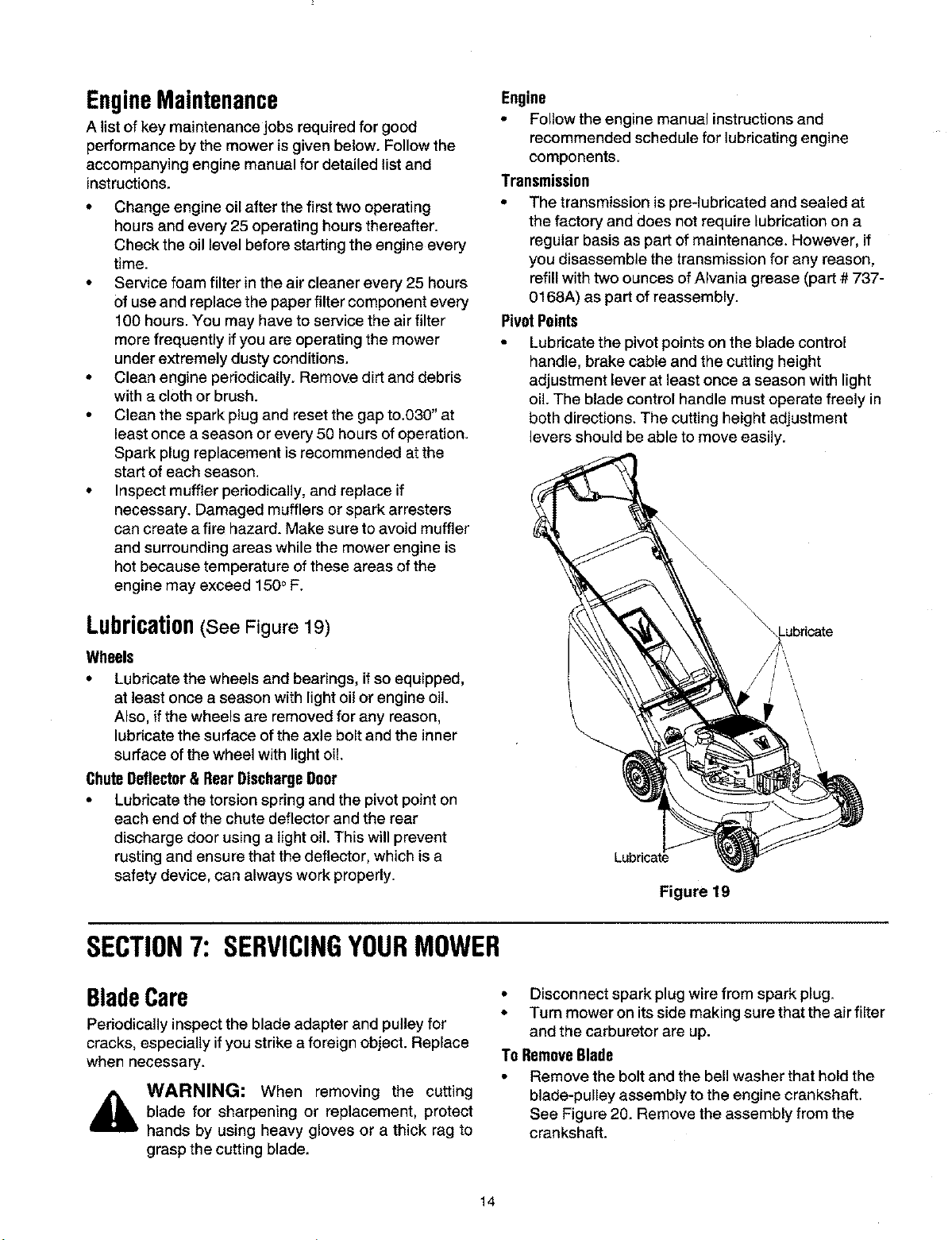
Lubrication(See Figure 19)
Wheels
• Lubricate the wheels and bearings, if so equipped,
at least once a season with light oil or engine oil.
Also, if the wheels are removed for any reason,
lubricate the surface of the axle bolt and the inner
surface of the wheel with light oil.
ChuteDeflector& RearDischargeDoor
• Lubricate the torsion spring and the pivot point on
each end of the chute deflector and the rear
discharge door using a light oil. This will prevent
rusting and ensure that the deflector, which is a
safety device, can always work properly.
Engine
• Follow the engine manual instructions and
recommended schedule for lubricating engine
components.
Transmission
• The transmission is pre4ubricated and sealed at
the factory and does not require lubrication on a
regular basis as part of maintenance. However, if
you disassemble the transmission for any reason,
refill with two ounces of Alvania grease (part # 737-
0168A) as part of reassembly.
PivotPoints
• Lubricate the pivot points on the blade control
handle, brake cable and the cutting height
adjustment lever at least once a season with light
oil. The blade control handle must operate freely in
both directions. The cutting height adjustment
levers should be able to move easily.
\
/ \
Figure 19
SECTION7: SERVICINGYOURMOWER
BladeCare
Pedodically inspect the blade adapter and pulley for
cracks, especially ifyou strike a foreign object. Replace
when necessary.
WARNING: When removing the cutting
blade for sharpening or replacement, protect
hands by using heavy gloves or a thick rag to
grasp the cutting blade.
• Disconnect spark plug wire from spark plug.
• Turn mower on its side making sure that the air filter
and the carburetor are up.
To RemoveBlade
Remove the bolt and the bell washer that hold the
blade-pulley assembly to the engine crankshaft.
See Figure 20. Remove the assembly from the
crankshaft.
14
• Remove the two bolts and lock nuts from the blade
assembly,
• Remove the blade from blade adapter and pulley.
To ReplaceBlade:
• Before reinstalling the blade-pulley assembly to the
unit, lubricate the engine crankshaft and the inner
surface of the blade adapter with light oil.
• Also lubricate the bolt holes, bolt and the inner
surface of the nuts.
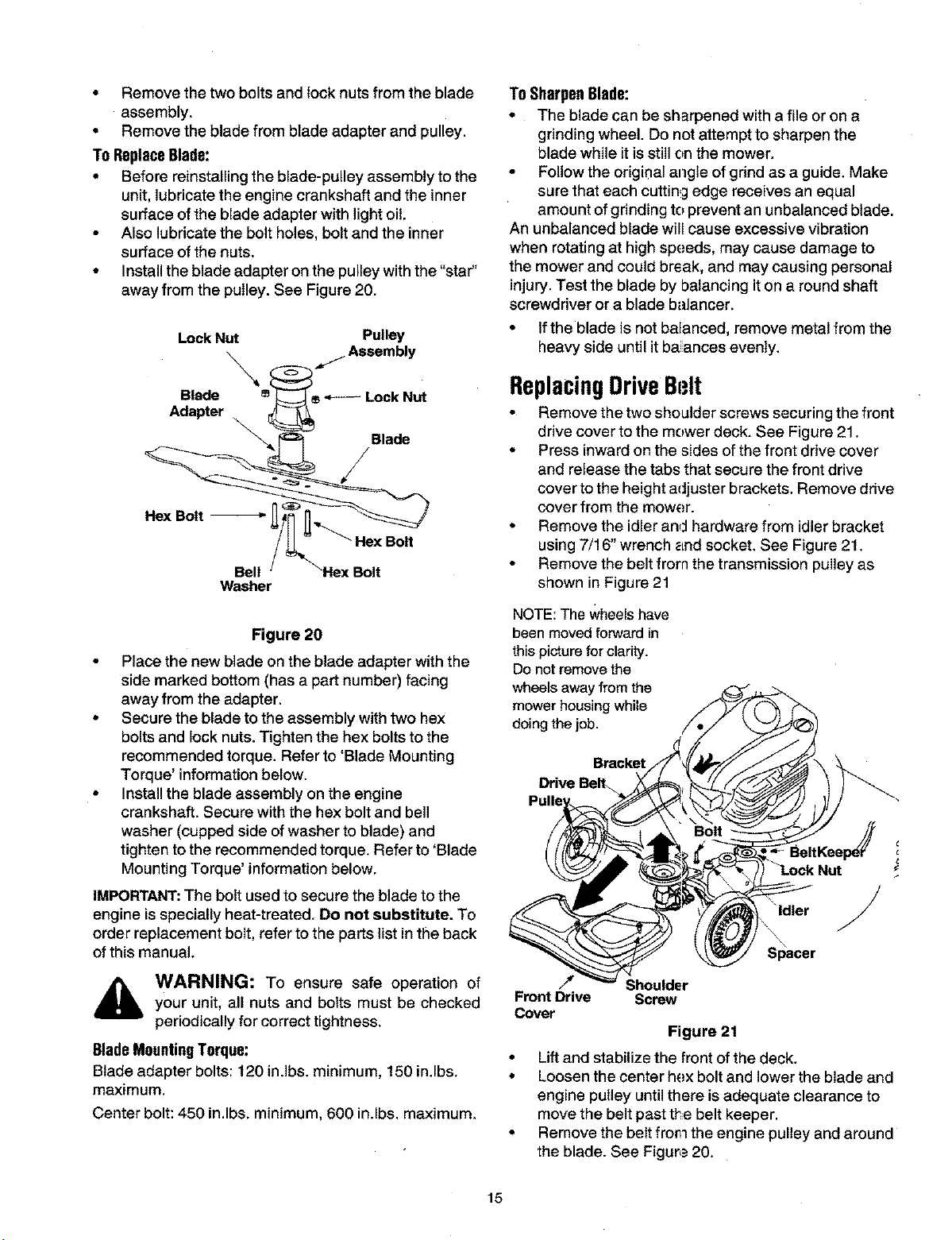
• Install the blade adapter on the pulley with the "star"
away from the pulley. See Figure 20.
Lock Nut Pulley
Washer
Figure 20
• Place the new blade on the blade adapter with the
side marked bottom (has a part number) facing
away from the adapter.
• Secure the blade to the assembly with two hex
bolts and lock nuts. Tighten the hex bolts to the
recommended torque. Refer to 'Blade Mounting
Torque' information below.
• Install the blade assembly on the engine
crankshaft. Secure with the hex bolt and bell
washer (cupped side of washer to blade) and
tighten to the recommended torque. Refer to 'Blade
Mounting Torque' information below,
IMPORTANT:The bolt used to secure the blade to the
engine is specially heat-treated. Do not substitute. To
order replacement bolt, refer to the parts list in the back
of this manual.
_ WARNING: To ensure safe operation ofyour unit, all nuts and bolts must be checked
periodically for correct tightness.
BladeMountingTorque:
Blade adapter bolts: 120 in.lbs, minimum, 150 in.lbs.
maximum,
Center bolt: 450 in.lbs, minimum, 600 in.lbs, maximum,
To SharpenBlade:
• The blade can be sharpened with a file or on a
grinding wheel. Do not attempt to sharpen the
blade while it is still on the mower.
• Follow the origir_al angle of grind as a guide. Make
sure that each cutting edge receives an equal
amount of grinding to prevent an unbalanced blade.
An unbalanced blade will cause excessive vibration
when rotating at high speeds, may cause damage to
the mower and could break, and may causing personal
injury. Test the blade by balancing it on a round shaft
screwdriver or a blade balancer.
• Ifthe blade is not balanced, remove metal from the
heavy side until it ba ances evenly.
ReplacingDriveBt;It
• Remove the two shoulder screws securing the front
drive cover to the mower deck. See Figure 21.
• Press inward on the sides of the front drive cover
and release the tabs that secure the front drive
cover to the height adjuster brackets. Remove drive
cover from the mower.
• Remove the idler and hardware from idler bracket
using 7/16" wrench _=ndsocket. See Figure 21.
• Remove the belt from the transmission pulley as
shown in Figure 21
NOTE:The Wheelshave
been moved forward in
this picturefor clarity.
Donot remove the
wheels away from the
mower housing while
doing the job.
Bracket
Drive BeE
"_ldler /
\
Sl_acer
/_ Shoulder
Front Drive Screw
Cover
Figure 21
• Lift and stabilize the front of the deck.
• Loosen the center hex bolt and lower the blade and
engine pulley until there isadequate clearance to
move the belt past the belt keeper,
• Remove the belt from the engine pulley and around
the blade. See Figure 20.
15
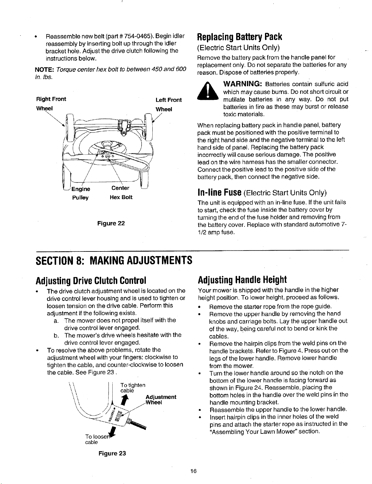
Reassemble new belt (part # 754-0465). Begin idler
reassembly by inserting bolt up through the idler
bracket hole. Adjust the drive clutch following the
instructions below.
NOTE" Torque center hex bolt to between 450 and 600
in. Ibs,
Right Front Left Front
Wheel Wheel
\
Engine Center
Pulley Hex Bolt
Figure 22
ReplacingBatteryPack
(Electric Start Units Only)
Remove the battery pack from the handle panel for
replacement only, Do not separate the batteries for any
reason. Dispose of batteries properly.
WARNING: Batteries contain sulfuric acid
which may cause burns. Do not short circuit or
mutilate batteries in any way. Do not put
batteries in fire as these may burst or release
toxic materials.
When replacing battery pack in handle panel, battery
pack must be positionedwith the positive terminal to
the right hand side and the negative terminal to the left
hand side of panel, Replacing the battery pack
incorrectly will cause serious damage. The positive
lead on the wire harness has the smaller connector.
Connect the positive lead to the positive side of the
battery pack, then connect the negative side.
In-lineFuse(Electric Start Units Only)
The unit is equipped with an in-line fuse. If the unit fails
to start, check the fuse inside the battery cover by
turning the end of the fuse holder and removing from
the battery cover. Replace with standard automotive 7-
1/2 amp fuse.
SECTION8: MAKINGADJUSTMENTS
AdjustingDriveClutchControl
• The drive clutch adjustment wheel is located on the
drive control lever housing and is used to tighten or
loosen tension on the drive cable. Perform this
adjustment if the following exists.
a. The mower does not propel itself with the
drive control lever engaged.
b. The mower's drive wheels hesitate with the
drive control lever engaged.
• To resolvethe above problems, rotate the
adjustment wheel with your fingers: clockwise to
tighten the cable, and counter-clockwise to loosen
the cable. See Figure 23.
To tighten
cable
To Iooser_
cable
Figure 23
AdjustingHandleHeight
Your mower isshipped with the handle in the higher
height position. To lower height, proceed as follows.
• Remove the starter rope from the rope guide.
• Remove the upper handle by removing the hand
knobs and carriage bolts. Lay the upper handle out
of the way, being careful net to bend or kink the
cables.
• Remove the hairpin clips from the weld pins on the
handle brackets. Refer to Figure 4. Press out on the
legs of the lower handle. Remove lower handle
from the mower,
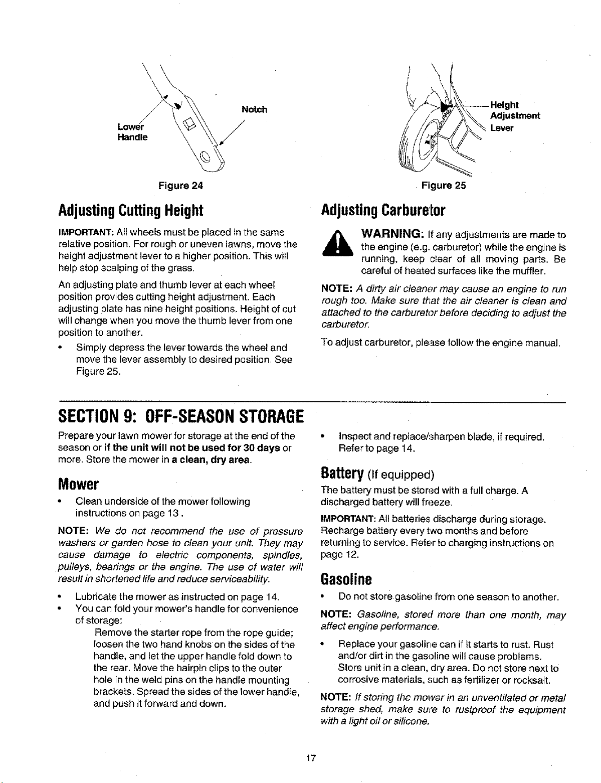
• Turn the lower handle around so the notch on the
bottom of the lower handle is facing forward as
shown in Figure 24. Reassemble, placing the
bottom holes in the handle over the weld pins in the
handle mounting bracket.
• Reassemble the upper handle to the lower handle,
• Insert hairpin clips in the inner holes of the weld
pins and attach the starter rope as instructed in the
"Assembling Your Lawn Mower" section.
16
\
Notch
Lower //Handle
Figure 24
AdjustingCuttingHeight
IMPORTANT:All wheels must be placed in the same
relative position. For rough or uneven lawns, move the
height adjustment lever to a higher position. This will
help stop scalping of the grass.
An adjusting plate and thumb lever at each wheel
position provides cutting height adjustment. Each
adjusting plate has nine height positions. Height of cut
will change when you move the thumb lever from one
position to another.
• Simply depress the lever towards the wheel and
move the lever assembly to desired position. See
Figure 25.
_-- Height
_ _._ Adjustment
Figure 25
AdjustingCarburetor
WARNING: If any adjustments are made to
the engine (e.g. carburetor) while the engine is
running, keep clear of all moving parts. Be
careful of heated surfaces like the muffler.
NOTE: A dirty air cleaner may cause an engine to run
rough too. Make sure that the air cleaner is clean and
attached to the carburetor before deciding to adjust the
carburetor.
To adjust carburetor, please follow the engine manual.
SECTION9: OFF-SEASONSTORAGE
Prepare your lawn mower for storage at the end of the
season or if the unit will not be used for 30 days or
more. Store the mower in a clean, dry area.
Mower
• Clean underside of the mower following
instructionson page 13.
NOTE: We do not recommend the use of pressure
washers or garden hose to clean your unit. They may
cause damage to electric components, spindles,
pulleys, bearings or the engine. The use of water will
result in shortened life and reduce serviceability.
Lubricate the mower as instructedon page 14.
You can fold your mower's handle for convenience
of storage:
Remove the starter rope from the rope guide;
loosen the two hand knobs on the sides of the
handle, and let the upper handle fold down to
the rear, Move the hairpin clips to the outer
hole in the weld pins on the handle mounting
brackets. Spread the sides of the lower handle,
and push it forward and down.
• Inspect and repIace/sharpen blade, if required.
Refer to page 14.
Battery(If equipped)
The battery must be ston.=dwith a full charge. A
discharged battery will freeze.
IMPORTANT:All batteries discharge during storage.
Recharge battery every two months and before
returning to service. Refer to charging instructions on
page 12.
Gasoline
• Do not store gasoline from one season to another.
NOTE: Gasoline, stored more than one month, may
affect engine performance,
Replace your gasoline can ifitstarts to rust, Rust
and/or dirt in the gasoline will cause problems.
Store unit in a clean, dry area. Do not store next to
corrosive materials, such as fertilizer or rocksalt.
NOTE: If storing the mower in an unventilated or metal
storage shed, make sure to rustproof the equipment
with a light off or silicone,
17
Engine
• Clean engine and remove any grass clippings, dirt,
and debris from the cooling fins, air intake screen,
levers, linkage and the exterior of the engine.
• Follow recommendations in the accompanying
engine manual for off-season storage of the
engine.
• Change oil as stated in the engine manual.
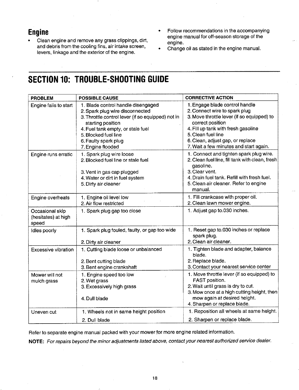
SECTION10: TROUBLE-SHOOTINGGUIDE
PROBLEM
Engine fails to start
Engine runs erratic
POSSIBLE CAUSE
1. Blade control handle disengaged
2. Spark plug wire disconnected
3.Throttle control lever (if so equipped) not in
starting position
4. Fuel tank empty, or stale fuel
5. Blocked fuel line
6. Faulty spark plug
7. Engine flooded
1. Spark plug wire loose
2. Blocked fuel line or stale fuel
3. Vent in gas cap plugged
4. Water or dirt in fuel system
5. Dirty air cleaner
CORRECTIVE ACTION
1.Engage blade control handle
2.Connect wire to spark plug
3. Move throttle lever (if so equipped) to
correct position
4. Fill up tank with fresh gasoline
5.Clean fuel line
6. Clean, adjust gap, or replace
7.Wait a few minutes and start again.
1. Connect and tighten spark plug wire.
2. Clean fuel line, fill tank with clean, fresh
gasoline.
3.Clear vent.
4. Drain fuel tank. Refill with fresh fuel.
5.Clean air cleaner. Refer to engine
manual.
Engine overheats 1. Engine oil level low 1. Fill crankcase with proper oil.
2. Air flow restricted 2.Clean lawn mower engine.
Occasional skip 1. Spark plug gap too close 1. Adjust gap to:030 inches,
(hesitates) at high
speed
Idles poorly 1. Spark plug fouled, faulty, or gap too wide 1. Reset gap to.030 inches or replace
spark plug.
2. Dirty air cleaner 2. Clean air cleaner.
Excessive vibration 1. Cutting blade loose or unbalanced 1. Tighten blade and adapter, balance
blade.
2. Bent cutting blade 2. Replace blade.
3,Bent engine crankshaft 3. Contact your nearest service center
Mower will not 1. Engine speed too low 1. Move throttle lever (if so equipped) to
mulch grass 2.Wet grass FAST position.
3.Excessively high grass 2. Wait until grass is dry to cut.
3. Mow once at a high cutting height, then
4.Dull blade mow again at desired height.
4. Sharpen or replace blade.
Uneven cut 1. Wheels not in same height position 1. Reposition all wheels at same height,
2. Dull blade 2, Sharpen or replace blade.
Refer to separate engine manual packed with your mower for more engine related information,
NOTE: For repairs beyond the minor adjustments listed above, contact your nearest authorized service dealer,
18
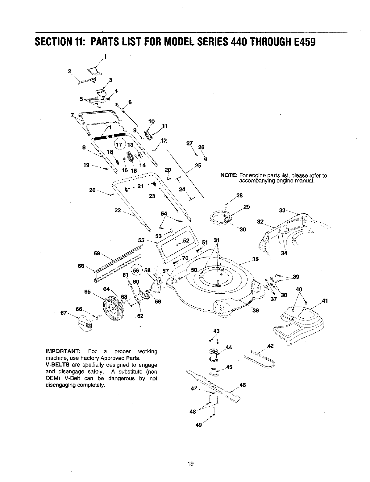
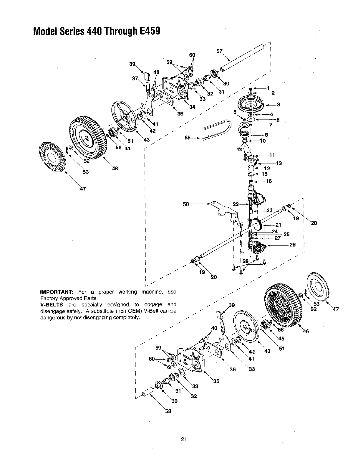
SECTION11: PARTSLISTFORMODELSERIES440 THROUGHE459
jl
2
7
20_
27
'\ 26
25
NOTE: For engine parts lis:t, please refer to
accompanying engine manual.
67_
65
62
59
36
40
38
IMPORTANT: For a proper working
machine, use Factory Approved Parts,
V-BELTS are specially designed to engage
and disengage safely. A substitute (non
OEM) V-Belt can be dangerous by not
disengaging completely.
.42
19
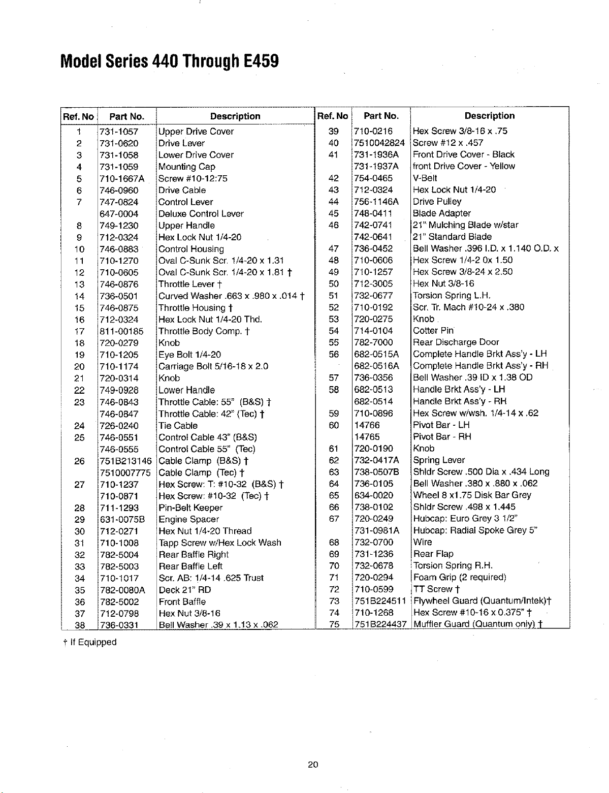
ModelSeries440 ThroughE459
Ref. No PaN No.
1 731-1057
2 731-0620
3 731-1058
4 731-1059
5 710-1667A
6 746-0960
7 747-0824
647-0004
8 749-1230
9 712-0324
10 746-0883
11 710-1270
12 710-0605
13 746-0876
14 736-0501
15 746-0875
16 712-0324
17 811-00185
18 720-0279
19 710-1205
20 710-1174
21 720-0314
22 749-0928
23 746-0843
746-0847
24 726-0240
25 746-0551
746-0555
26 751B213146
7510007775
27 710-1237
710-0871
28 711-1293
29 631-0075B
30 712-0271
31 710-1008
32 782-5004
33 782-5003
34 710-1017
35 782-0080A
36 782-5002
37 712-0798
38 736-0331
t If Equipped
Description
Upper Drive Cover
Drive Lever
Lower Drive Cover
Mounting Cap
Screw #10-12:75
Drive Cable
Control Lever
Deluxe Control Lever
Upper Handle
Hex Lock Nut 1/4-20
Control Housing
Oval C-Sunk Scr. 1/4-20 x 1,31
Oval C-Sunk Scr. 1/4-20 x 1,81 1"
Throttle Lever 1"
Curved Washer .663 x .980 x .0t4 1
Throttle Housing 1"
Hex Lock Nut 1/4-20 Thd.
Throttle Body Comp. t
Knob
Eye Bolt 1/4-20
Carriage Bolt 5/16-18 x 2_0
Knob
Lower Handle
Throttle Cable: 55" (B&S) 1
Throttle Cable: 42" (Tec) 1"
Tie Cable
Control Cable 43" (B&S)
Control Cable 55" (Tec)
Cable Clamp (B&S) l-
Cable Clamp (Tec) 1"
Hex Screw: T: #10-32 (B&S) t
Hex Screw: #10-32 (Tec) l
Pin-Belt Keeper
Engine Spacer
Hex Nut 1/4-20 Thread
Tapp Screw w/Hex Lock Wash
Rear Baffle Right
Rear Baffle Left
Scr. AB: 1/4-14.625 Trust
Deck 21" RD
Front Baffle
Hex Nut 3/8-16
Bell Washer .39 x 1,13 x .062
Ref. No
39
4O
4!
42
43
44
45
46
47
48
49
5O
51
52
53
54
55
56
57
58
59
60
61
62
63
64
65
66
67
68
69
70
71
72
73
74
75
Part No.
710-0216
751OO42824
731-1936A
731-1937A
754-0465
712-0324
756-1146A
748-0411
742-0741
742-0641
736-0452
710-0606
710-1257
712-3005
732-0677
710-0192
720-0275
714-0104
782-7000
682-0515A
682-0516A
736-0356
682-0513
682-0514
710-0896
14766
14765
720-0190
732-0417A
738-0507B
736-0105
634-0020
738-0102
720-0249
731-0981A
732-0700
731-1236
732-0678
720-0294
710-0599
751B224511
710-1268
751B224437
Description
Hex Screw 3/8-16 x .75
Screw #12 x .457
Front Drive Cover - Black
front Drive Cover - Yellow
V-Belt
Hex Lock Nut 1/4-20
Drive Pulley
Blade Adapter
21" Mulching Blade w/star
21" Standard Blade
Bell Washer .396 I.D. x 1.140 O.D. x
Hex Screw 1/4-2 0x 1.50
Hex Screw 3/8-24 x 2,50
Hex Nut 3/8-16
Torsion Spring L.H,
Scr. Tr. Mach #10-24 x ,380
Knob
Cotter Pin
Rear Discharge Door
Complete Handle Brkt Ass'y - LH
Complete Handle Brkt Ass'y - RH
Bell Washer .39 ID x 1.38 OD
Handle Brkt Ass'y - LH
Handle Brkt Ass'y - RH
Hex Screw w/wsh. 1/4-14 x .62
Pivot Bar - LH
Pivot Bar - RH
Knob
Spring Lever
Shldr Screw .500 Dia x .434 Long
Bell Washer .380 x .880 x .062
Wheel 8 x1.75 Disk Bar Grey
Shldr Screw .498 x 1.445
Hubcap: Euro Grey 3 1/2"
Hubcap: Radial Spoke Grey 5"
Wire
Rear Flap
Torsion Spring R.H.
!Foam Grip (2 required)
]TT Screw 1.
iFlywheel Guard (Quantum!lntek)t
Hex Screw #10-16 x 0.375 1.
Muffler Guard (Quantum on y) 1
2O
ModelSeries440 ThroughE459
40
37\
\
46
44
J
J
J
J
7
IMPORTANT: For a proper working machine, use
Factory Approved Parts,
V-BELTS are specially designed to engage and
disengage safely. A substitute (non OEM) V-Belt can be
dangerous by not disengaging completely. .f
J
/,
59
I
i
I
57
50_--_<
2O
4O
25
43 51
52
21

ModelSeries440 ThroughE459
Rs_ No PaR No.
1. 712-3025
2. 736-O425
3. 756-1042
4. 736-0425
5. 712-0896
6. 736-0406
7. 782-7598
8. 741-0124
9. 721-0457
10. 750-1050 .
11. 682-0028
12. 741-0682A
13. 732-0849A
14. 710-0299
15. 736-0570
16. 741-0699
17. 721-0325
18. 618-0300A
19. 721-0329
20. 741-0673
21. 611-0105
22. 736-0520
23. 717-1492
24. 736-0314
25. 736-0569
26. 618-0299A
27. 741-0672
28. 710-1276
29. 618-0298B
30. 732-O7O8
Description
Hex Jam Nut 5/16-24
Bell Washer .325 x .930 x .045
Pulley, 3.82 x .313 x .68
Bell Washer .325 x .930 x .045
Lock Nut 1/4-28
Flat Washer .442 x 1.38 x .060
Belt Keeper
Ball Bearing
Oil Seal
Flange Spacer
Idler Bracket Assembly
Bearing Sleeve
Flat Washer .504 x .700 x.030
Hex Cap Screw 1/4-28 x 1.00
Flat Washer .865 x 1.145 x .030
Needle Bearing .438 x .625 x .500
Plug 1/4x .437
Upper Housing
Oil Seal .500 x .687 x .094
Flange Bearing
Output Shaft
Flat Washer .504 x .700 x .030
Pinion Shaft 10T
Thrust Washer .375 x .70 x .030
Thrust Washer .388 x .625 x .062
Lower Housing
Flange Bearing .378 x .531 x .370
Hex Screw w/Washer 1/4-20 x .750
Transmission Assembly
(includes Ref. # 1to Ref. #30)
Bearing Retainer
Ref.No
31.
32.
33.
34.
35.
36,
37.
38.
39.
40,
41.
42.
43,
44.
45.
46.
47.
48,
49.
50,
51.
52.
53,
54,
55.
56.
57.
58.
59,
60.
Part No.
!741-0604
i748-0355
736-0447
782-0512B
782-0511A
682-0509
732-0706
732-0707
720-0190
710-0216
736-0474
716-0102
782-7551
717-1762
717-1761
634-0021A
731-0981A
720-0249
682-0512A
682-0511A
682-0030
715-0221
786-3013
714-0101
738-1002
754-0465
716-0865
750-1165
750-1166
736-0331-
712-0798
Description
Bearing Sleeve .50 I.D.
Bearing Support
Wave Washer 1.5 x 1.0 x .029
RH Height Adj. Plate
LH Height Adj. Plate
Pivot Plate Assembly
RH Front Lever
LH Front Lever
Knob
Hex Cap Screw 3/8-16 x .75
Washer DD 1.5"O.D.
Snap Ring 1.0 die.
Wheel Dust Cap
Gear 14T R.H.
Gear 14T L.H.
Wheel, 8x2 x 1.75
Hubcap: Gray
!Hubcap: Euro Gray
RH Height Adj. Complete
LH Height Adj. Complete
Cable Idler Bracket
Dowel Pin
Flat Washer 1/2 x 1.00 x .063
Cotter Pin .08 x 1.42
Screw
Belt
Snap Ring
Slev. Spacer
Slev. Spacer
Bell Washer
Hex Nut 3/8-16
22
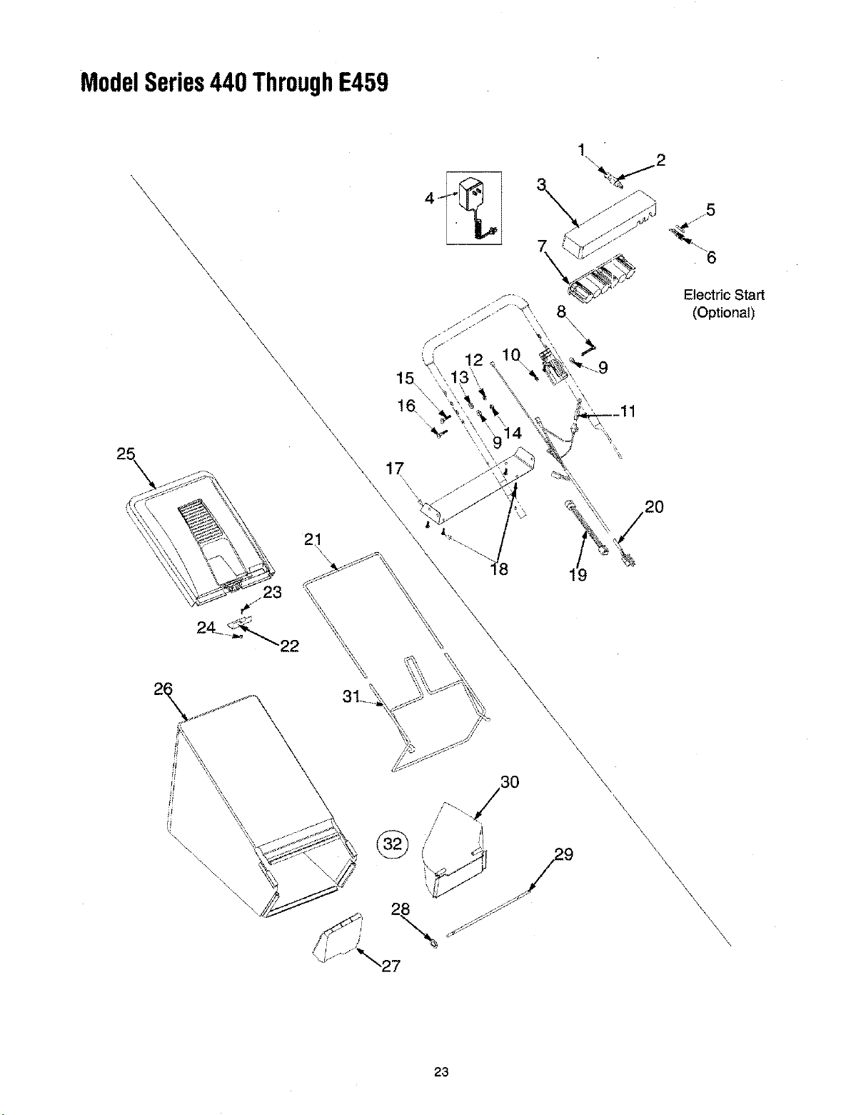
ModelSeries440 ThroughE459
\
\
\
\
\
\
\
\
\
\
\
\
\
\
\
\
\
\
\ 21_
\
\
\
X
\
j5
"6
Electric Start
(Optional)
\
\
\\
"\\\ \\
\
\
\
\,
\
\
\
\
\
\
23
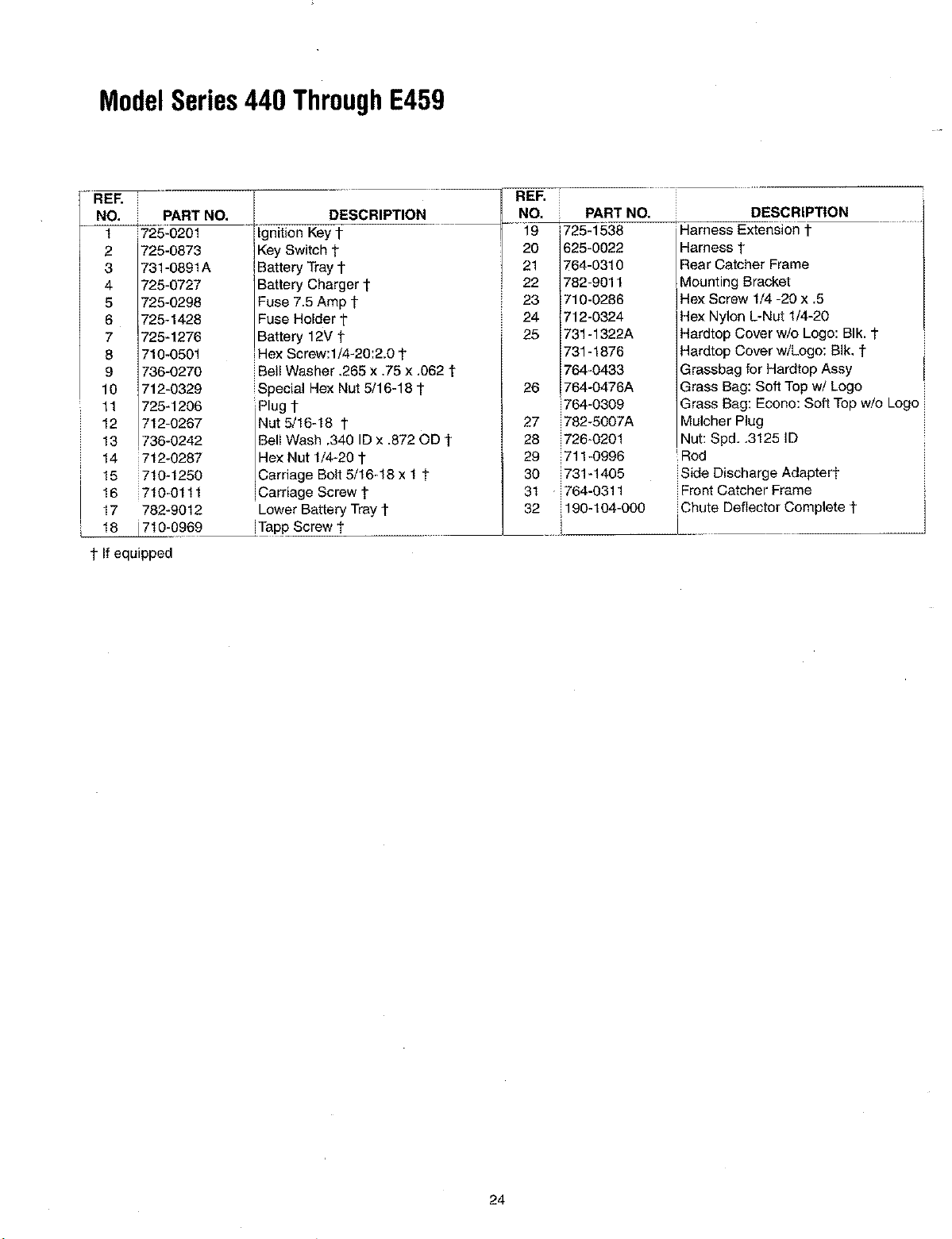
ModelSeries440 ThroughE459
REF.
NO. PART NO.
t 725-0201
2 725-0873
3 731-0891A
4 725-0727
5 725-0298
6 725-1428
7 725-1276
8 710-0501
9 736-0270
10 712-0329
11 725-1208
12 712-0267
13 736-0242
14 712-0287
i 15 710-1250
16 710-0111
17 782-9012
_710-0969
t If equipped
DESCRIPTION
gnton KeYt
Key Switch 1-
Battery Tray t
Battery Charger 1"
Fuse 7.5 Amp t
Fuse Holder t
IBattery 12V t
Hex Screw:l/4-20:2.0 t
Bell Washer ,265 x #5 x .062 t
Special Hex Nut 5ll 6-18 1
Plug l-
Nut 5/16-18 1-
Bell Wash 340 ID x .872 OD t
Hex Nut 1/4-20 1-
Carriage Bolt 5/16-18 x ! t
Carriage Screw t
Lower Battery Tray t
!Tapp Screw t
REF,
NO,
19
20
21
22
23
24
25
26
27
28
29
30
31
32
PART NO.
725-1538
625-0022
764-0310
782-9011
710-0286
712-0324
731 -1322A
731 -1876
764-0433
764-0476A
764-0309
782-5007A
726-020!
711-0996
731-1405
764-0311
190-104-000
DESCRIPTION
Harness Extension t
Harness 1"
Rear Catcher Frame
Mounting Bracket
Hex Screw 1/4 -20 x .5
Hex Nylon L-Nut 1/4-20
Hardtop Cover wio Logo: BIk. t
Hardtop Cover w/Logo: BIk, 1
I
Grassbag for Hardtop Assy I
Grass Bag: Soft Top w/Logo
Grass Bag: Econo: Soft Top wio Logo
Mulcher Plug
Nut: Spd..3125 ID
Rod
Side Discharge Adaptert
Front Catcher Frame
Chute Deflector Complete t
24
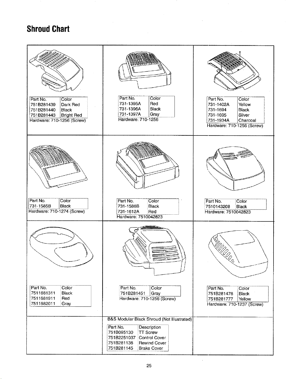
ShroudChart
Part No. Color
751B281439 Dark Red
i
751B281440 Black
751B261443 Bright Red
Hardware: 710-1256 (Screw)
Part No. Color
731-1585B Black
Hardware: 710-1274 (Screw)
Part No. iColor
7511681311 iBlack
7511681911 iRed
7511682011 iGray
iPart No, Color
i73!-1395A Red
i731-1396A Black
_3111397A Gray
Hardware:710-1256
Part No. Color
731-1566B Black
731-1612A Red
Hardware: 7510042823
Part No. Color
751B281451 Gray
Hardware: 710-1256 (Screw)
B&S Modular Black Shroud (Not Illustrated
Part No. _Description
751B095130 ITT Screw
751B2251037 Control Cover
[751B281136 Rewind Cover
L751B281145 Brake Cover
Part No, Color q
731-1402A Yellow
731-1694 Black
731-1695 Silver
731-1934A Charcoal E
J
Hardware: 710-1256 (Screw)
_Part No. _loT
7510143208 Black
Hardware: 7510042823
Part No. Color
751B281476 Black
751B281777 Yellow i
14ardware: 710-1237 (Screw)
25

Date
YOURNOTES
Comments
26

Date
Your Notes (Contd.)
Comments
27
MANUFACTURER'S LIMITED WARRANTY FOR:
The limited warranty set forth below is given by MTD
PRODUCTS INC ("MTD") with respect to new merchandise
purchased and used in the United States, its possessions
and territories.
MTD warrants this product against defects in material and
workmanship for a period of two (2) years commencing on
the date of original purchase and will, at its option, repair or
replace, free of charge, any part found to be defective in
material or workmanship. This limited warranty shall only
apply if this product has been operated and maintained in
accordance with the Operator's Manual furnished with the
product, and has not been subject to misuse, abuse, com-
mercial use, neglect, accident, improper maintenance,
alteration, vandalism, theft, fire, water or damage because
of other peril or natural disaster. Damage resulting from the
installation or use of any accessory or attachment not
approved by MTD Products Inc. for use with,the product(s)
covered by this manual will void your warranty as to any
resulting damages.
Normal wear parts or components thereof are subject to
separate terms as follows: All normal wear part or compo-
nent failures will be covered on the product for a period of
90 days regardless of cause. After 90 days, but within the
two year period, normal wear part failures will be covered
ONLY IF caused by defects in material or workmanship of
OTHER component parts. Normal wear parts and compo-
nents include, but are not limited to, belts, blades, blade
adapters, grass bags, rider deck wheels, seats, snow
thrower skid shoes, shave plates and tires. Batteries are
covered by a 90-day limited replacement warranty.
HOW TO OBTAIN SERVICE: Warranty service is available,
WITH PROOF OF PURCHASE THROUGH YOUR LOCAL
AUTHORIZED SERVICE DEALER. To locate the dealer in
your area, please check for a listing in the Yellow Pages or
contact the Customer Service Department of MTD PROD-
UCTS INC by calling 1-800-800-7310 or writing to RO. Box
368022, Cleveland, Ohio 44136-9722.
This limited warranty does not provide coverage in the
following eases:
a. The engine or component parts thereof. These items
carry a separate manufacturer's warranty. Please refer
to the applicable manufacturer's warranty on these
items.
b. Log splitter pumps, valves and cylinders have a sepa-
rate one year warranty.
c. Routine maintenance items such as lubricants, filters,
blade sharpening and tune-ups, or adjustments such
as brake adjustments, clutch adjustments or deck
adjustments; and normal deterioration of the exterior
finish due to use or exposure.
d. MTD does not extend any warranty for products sold
or exported outside of the United States of America,
its possessions and territories, except those sold
through MTD's authorized channels of export distribu-
tion.
No implied warranty, including any implied warranty of
merchantability or fitness for a particular purpose,
applies after the applicable period of express written
warranty above as to the parts as identified. No other
express warranty or guaranty, whether written or oral,
except as mentioned above, given by any person or
entity, including a dealer or retailer, with respect to any
product shall bind MTD. During the period of the War-
ranty, the exclusive remedy is repair or replacement of
the product as set forth above. (Some states do not
allow limitations on how long an implied warranty lasts, so
the above limitation may not apply to you.)
The provisions as set forth in this Warranty provide the
sole and exclusive remedy arising from the sales. MTD
shall not be liable for incidental or consequential loss
or damages including, without limitation, expenses
incurred for substitute or replacement lawn care ser-
vices, for transportation or for related expenses, or for
rental expenses to temporarily replace a warranted
product. (Some states do not allow the exclusion or limita-
tion of incidental or consequential damages, so the above
exclusion or limitation may not apply to you.)
In no event shall recovery of any kind be greater than the
amount of the purchase price of the product sold. Alteration
of the safety features of the product shaiI void this War-
ranty. You assume the risk and liability for loss, damage, or
injury to you and your property and/or to others and their
property arising out of the use or misuse or inability to use
the product.
This limited warranty shall not extend to anyone other than
the original purchaser, original lessee or the person for
whom it was purchased as a gift.
How State Law Relates to this Warranty: This limited
warranty gives you specific legal rights, and you may also
have other rights which vary from state to state.