perator's Manual
£RnFrSMRN°
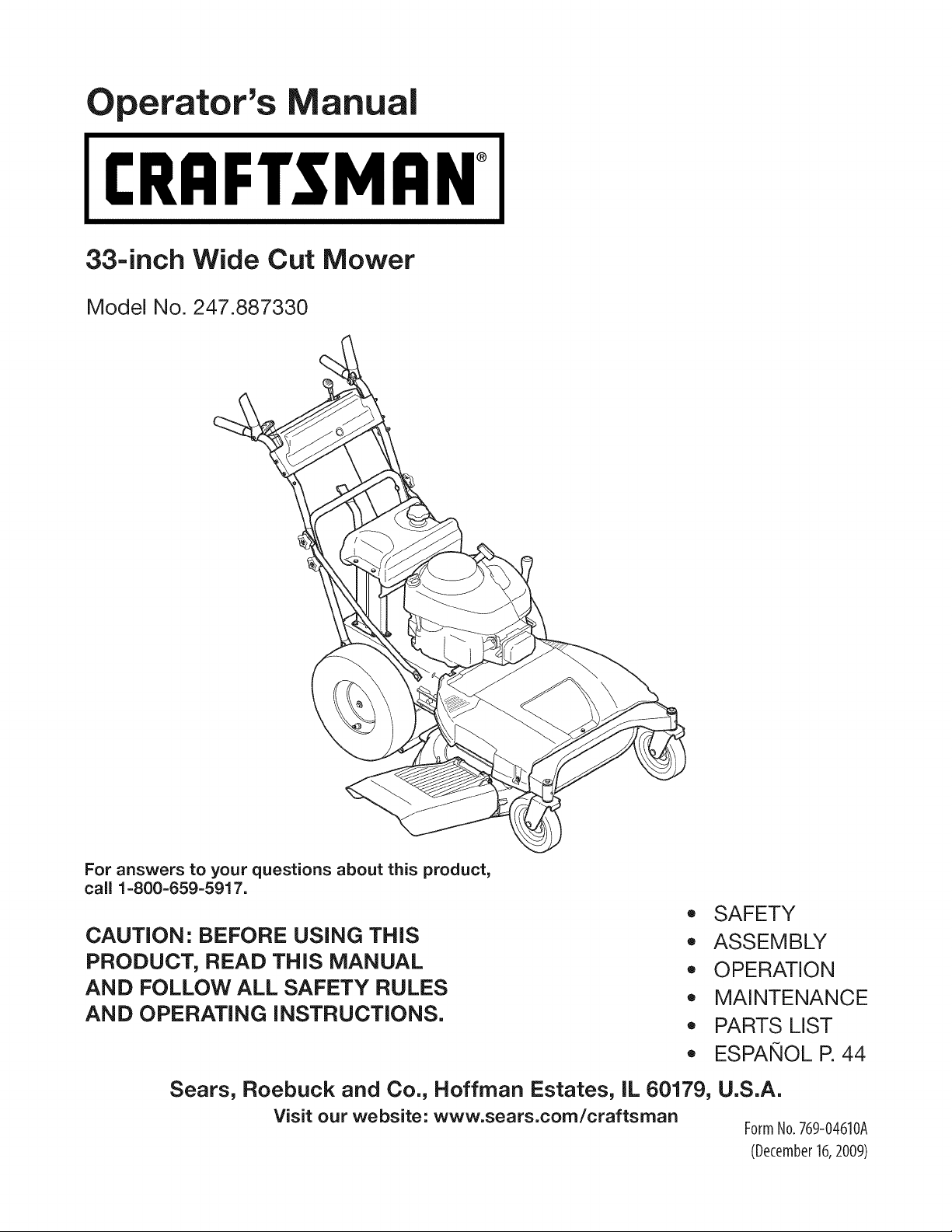
33-inch Wide Cut Mower
Model No. 247.887330
For answers to your questions about this product,
call 1-800-659-5917.
CAUTION: BEFORE USING THiS
PRODUCT, READ THiS MANUAL
AND FOLLOW ALL SAFETY RULES
AND OPERATING iNSTRUCTiONS.
,, SAFETY
,, ASSEMBLY
,, OPERATION
,, MAINTENANCE
,, PARTS LIST
,, ESPAIf,IOL R 44
Sears, Roebuck and Co., Hoffman Estates, IL 60179, U.S.A.
Visit our website: www.sears.com/craftsman
FormNo.769-04610A
(December16,2009)
Warranty Statement .......................................................... 2
Safety Instructions ............................................................ 3
Slope Guide ....................................................................... 5
Safety Labels .................................................................... 6
Assembly ........................................................................... 8
Know your Lawn Mower .................................................. 10
Operation ........................................................................ 12
CRAFTSMAN FULL WARRANTY
Whenoperatedand maintainedaccordingto allsuppliedinstructions,if this Craftsmanproductfailsdueto a defectin materialor workmanship
withintwoyearsfromthe date orpurchase,call 1-800-4-MY-HOME®to arrangefor free repair(or replacementif repairprovesimpossible).
Thiswarrantyappliesfor only90 daysfromthe dateof purchaseif this productis everusedfor commercialor rentalpurposes.
ThiswarrantycoversONLYdefectsin materialand workmanship.Searswill NOT payfor:
• Expendableitemsthatbecomewornduringnormaluse,includingbutnot limitedto blades,sparkplugs,aircleaners,belts,andoil filters.
Standardmaintenanceservicing,oilchanges,or tune-ups.
Tire replacementor repaircausedby puncturesfromoutsideobjects,suchas nails,thorns,stumps,or glass.
Tireor wheelreplacementor repairresultingfrom normalwear,accident,or improperoperationor maintenance.
Repairsnecessarybecauseof operatorabuse,includingbutnot limitedto damagecausedby impactingobjectsthat bendthe frameor
crankshaft,or over-speedingtheengine.
Repairsnecessarybecauseof operatornegligence,includingbut not limitedto,electricalandmechanicaldamagecausedby improper
storage,failureto usethe propergradeandamountof engineoil, failureto keepthe deckclearof flammabledebris,orfailureto maintainthe
equipmentaccordingto the instructionscontainedinthe operator'smanual.
Engine(fuelsystem)cleaningor repairscausedbyfuel determinedto becontaminatedoroxidized(stale).In general,fuel shouldbeused
within30 daysof itspurchasedate.
Normaldeteriorationandwearof the exteriorfinishes,or productlabel replacement.
Thiswarrantyappliesonly whilethisproductis withinthe UnitedStates.
Thiswarrantygivesyou specificlegalrights,andyou mayalso haveotherrightswhichvaryfromstateto state.
Sears, Roebuck and Co., Hoffman Estates, IL 60179
GrossHP: 10.5
EngineOil: SAE30
Fuel: UnleadedGasoline
SparkPlug: Champion®RC12YC
Engine: Briggs& StrattonPowerBuiltTM
Model Number
Serial Number
Dateof Purchase
Recordthe modelnumber,serialnumber,
anddateof purchaseabove.
© SearsBrands,LLC 2

__IL his symbolpointsout importantsafetyinstructions
which,ifnot followed,couldendangerthe personal
safetyand/or propertyof yourselfandothers.Read
andfollowall instructionsinthismanualbefore
attemptingto operatethis machine.Failureto complywith these
instructionsmayresultinpersonalinjury.Whenyou seethissymbol,
HEEDITSWARNING!
Your Responsibility: Restrictthe useof this powermachineto
personswhoread,understand,andfollowthe warningsand instruc-
tionsinthis manualandonthe machine.
Thismachinewasbuiltto beoperatedaccordingto the rulesfor
safeoperationinthis manual.As with anytype of powerequipment,
carelessnessorerroronthe partof the operatorcan resultin serious
injury.Thismachineis capableof amputatinghandsandfeetand
throwingobjects.Failureto observethefollowingsafetyinstructions
could resultin seriousinjury or death.
__ate of Californiato I
causecancerandbirthdefectsor otherreproductiveharm.
CHILDREN
Tragicaccidentscan occur if operatoris notalert to presenceof children.Chil-
dren areoften attractedto mowerandmowingactivity.Theydo notunderstand
thedangers.Neverassumethat childrenwillremainwhereyou lastsawthem.
,, Keepchildrenoutof the mowingarea and underwatchfulcare of a
responsibleadult otherthanthe operator.
,, Be alert andturn moweroff if a child entersthe area.
,, Beforeandwhile movingbackwards,look behindanddownfor small
children.
,, Useextremecare whenapproachingblind corners,doorways,shrubs,
trees, orotherobjectsthat mayobscureyourvisionof a childwho may
run into themower.
,, Keepchildrenawayfrom hotor runningengines.They can suffer burns
from a hot muffler.
,, Neverallow childrenunder 14yearsold to operatea power mower.
Children14years old and overshouldreadand understandoperation
instructionsand safetyrulesin this manualand shouldbe trainedand
supervisedbya parent.
GENERAL OPERATION
,, Readthis operator'smanualcarefullyin its entirety beforeattempting
to assemblethis machine.Read,understand,andfollow all instructions
on the machineand in the manual(s)beforeoperation.Be completely
familiarwith the controlsand the properuse of this machinebefore
operatingit. Keepthis manualin a safe placeforfuture andregular
referenceand for orderingreplacementparts.
,, Thismachineis a precisionpieceof powerequipment,not a plaything.
Therefore,exerciseextremecautionat all times.Your unit has been
designedto performonejob: to mowgrass. Do notuse itfor anyother
purpose.
,, Neverallow childrenunder 14yearsold to operatethis machine.
Children14years old and overshouldreadand understandthe instruc-
tions inthis manualand shouldbe trainedandsupervisedby a parent.
Onlyresponsibleindividualswho arefamiliar withthese rulesof safe
operationshouldbe allowedto usethis machine.
,, Thoroughlyinspectthe area wherethe equipmentis to be used.Remove
all stones,sticks,wire, bones,toysand otherforeignobjectswhichcould
be trippedoveror pickedup and thrownbythe blade.Thrownobjects
can causeseriouspersonalinjury.Plan yourmowingpatternto avoid
dischargeof materialtoward roads,sidewalks,bystandersandthe like.
Also,avoid dischargingmaterialagainst a wall orobstructionwhich may
causedischargedmaterialto ricochetback towardthe operator.
,, To helpavoid bladecontactor a thrownobject injury,stay in operator
zone behindhandlesand keepchildren, bystanders,helpers,and pets at
least75 feet from mowerwhile it is inoperation.Stopmachineif anyone
entersarea.
,, Alwayswearsafetyglassesor safetygoggles duringoperationand while
performingan adjustmentor repairto protectyoureyes.Thrownobjects
which ricochetcan causeserious injuryto theeyes.
,, Wearsturdy,rough-soledwork shoesandclose-fittingslacksandshirts.
Shirts and pantsthat coverthe armsand legs andsteel-toedshoes
are recommended.Neveroperatethis machinein barefeet, sandals,
slipperyor light weight(e.g.canvas) shoes.
,, Donot puthandsor feetnear rotating partsor undercutting deck.
Contactwith bladecan amputatehandsandfeet.
,, A missingor damageddischargecover can causebladecontact or
thrown objectinjuries.
,, Manyinjuriesoccur as a resultof the mowerbeingpulledoverthe foot
duringa fall causedby slippingor tripping.Do nothold on to the mowerif
you are falling;releasethe handleimmediately.
,, Neverpull the mowerbacktoward you whileyou are walking.If youmust
backthe mowerawayfrom a wall or obstructionfirst look downand
behindto avoidtripping andthenfollow thesesteps:
a. Step backfrom mowerto fully extendyourarms.
b.Be sureyou are wellbalancedwithsure footing.
c. Pull backslowly,nomorethan halfway towardsyou.
d. Repeatthese steps as needed.
,, Donot operatethe mowerwhile underthe influenceof alcoholor drugs.
,, Donot engagethe self-propelledmechanismon units so equippedwhile
startingengine.
,, The blade control handleis a safety device.Neverattemptto bypassits
operation.Doingso makesthe safetydeviceinoperativeand may result
inpersonalinjurythroughcontactwiththe rotatingblade.The blade
control handle mustoperateeasily inboth directionsand automatically
returnto the disengagedpositionwhen released.
,, Neveroperatethe mowerin wet grass.Alwaysbe sureof yourfooting. A
slip andfall can causeseriouspersonalinjury.If you feel youare losing
yourfooting, releasethe bladecontrol handleimmediatelyandthe blade
will stop rotatingwithinthreeseconds.
,, Mowonly in daylightor good artificiallight. Walk,neverrun.
,, Stopthe bladewhen crossing graveldrives,walksor roads.
3
• If theequipmentshould startto vibrateabnormally,stoptheengine and
check immediatelyfor the cause.Vibrationis generallya warningof
trouble.
• Shutthe engineoff andwait untilthe bladecomesto a completestop
beforeremovingthe grass catcheror uncloggingthe chute.
The cuttingblade continuesto rotatefor a fewseconds afterthe engine
is shut off.Neverplace any part of the bodyinthe bladearea untilyou
aresure the bladehas stoppedrotating.
• Neveroperatemowerwithoutpropertrailshield,dischargecover,grass
catcher,bladecontrol handle, orothersafety protectivedevicesin place
andworking.Neveroperatemowerwithdamagedsafetydevices.Failure
to doso can resultin personalinjury.
• Mufflerandengine becomehot and can causea burn.Do not touch.
• Only use partsand accessoriesmadefor this machineby manufacturer.
Failureto do so canresult in personalinjury. For recommendedacces-
sories,call 1-800-659-5917.
• If situationsoccurwhich are not coveredinthis manual,use careand
goodjudgment. ContactyourSears ServiceCenterfor assistance.
SLOPE OPERATION
Slopesare a major factorrelatedto slip andfall accidentswhichcan resultin
severeinjury.Operationon slopesrequiresextracaution.Ifyoufeel uneasyon
a slope,do notmow it.For yoursafety,usethe slopeguideincludedas part of
thismanualto measureslopesbeforeoperatingthis unit ona slopedor hilly
area.If theslope is greaterthan 15 degrees,do notmowit.
Do:
• Mow acrossthe faceof slopes; never up anddown. Exerciseextreme
cautionwhen changingdirectionon slopes.
• Watchfor holes,ruts,rocks, hiddenobjects,or bumpswhich cancause
youto slip or trip.Tall grasscan hideobstacles.
• Alwaysbe sureof your footing.A slip andfall can causeseriouspersonal
injury.If you feelyou are losingyour balance,releasethe bladecontrol
handleimmediately,andthe bladewill stoprotatingwithin3 seconds.
Do Not:
• Do not mow neardrop-offs, ditchesorembankments,whereyou could
lose yourfootingor balance.
• Do not mow slopesgreaterthan 15degreesasshown on the
slopegauge.
• Do not mow on wetgrass. Unstablefooting couldcauseslipping.
SERVICE
Safe Handling Of Gasoline:
• Toavoidpersonalinjuryor propertydamage useextreme care in
handlinggasoline.Gasolineis extremelyflammableandthe vapors are
explosive.Seriouspersonalinjurycan occurwhengasolineis spilledon
yourselfor yourclotheswhichcan ignite.
• Washyourskin andchangeclothesimmediately.
• Useonly an approvedgasolinecontainer.
• Neverfill containersinsidea vehicle oron a truckor trailerbedwith a
plastic liner.Alwaysplace containerson the groundawayfromyour
vehiclebeforefilling.
• Removegas-poweredequipmentfromthe truck or trailer and refuel it on
theground. If this is not possible,then refuelsuch equipmenton a trailer
witha portablecontainer,ratherthan from a gasolinedispensernozzle.
• Keepthe nozzlein contact with the rim of thefuel tank or container
openingat alltimes until fueling is complete.Donot usea nozzle
lock-opendevice.
• Extinguishallcigarettes,cigars, pipesand othersources
of ignition.
• Neverfuel machineindoors becauseflammablevapors will accumulate
inthe area.
• Neverremovegas cap or addfuel while engineis hot or running.
Allowengineto cool at least two minutesbeforerefueling.
• Neveroverfill fuel tank.Fill tank to no morethan V2inch belowbottom
of filler neckto provideforfuel expansion.
• Replacegasolinecap andtighten securely.
• If gasolineis spilled,wipe it off the engineand equipment.Moveunit
to anotherarea. Wait 5 minutesbeforestarting engine.
• Neverstorethe machineorfuel containernearan openflame,spark
or pilot light ason a waterheater,spaceheater,furnace,clothesdryer,
or othergas appliances.
• To reducefire hazard,keepmowerfree of grass, leaves,or other
debris build-up.Clean up oilor fuel spillageandremoveany fuel
soakeddebris.
• Allowa mowerto cool at least 5 minutesbeforestoring.
General Service:
• Neverrun an engine indoors or in a poorlyventilatedarea.Engine
exhaustcontainscarbon monoxide,an odorlessand deadlygas.
• Beforecleaning,repairing,or inspecting,makecertainthe bladeand
all movingparts havestopped.Disconnectthe sparkplugwire and
ground againsttheengine to preventunintendedstarting.
• Checkthe bladeand enginemountingboltsat frequentintervalsfor
propertightness.Also, visuallyinspectbladefor damage(e.g.,bent,
cracked,worn) Replacebladewith the original equipmentmanufac-
ture's(O.E.M.)bladeonly, listedin this manual.Use of parts whichdo
notmeetthe originalequipmentspecificationsmaylead to improper
performanceandcompromisesafety!
• Mowerbladesare sharpand can cut. Wrapthe bladeor weargloves,
and use extra cautionwhen servicingthem.
• Keepallnuts, bolts,andscrewstight to be surethe equipmentis in
safeworkingcondition.
• Nevertamperwith safetydevices.Checktheir proper
operationregularly.
• Afterstrikinga foreignobject, stoptheengine, disconnectthe spark
plugwire and groundagainstthe engine.Thoroughlyinspectthe
mowerfor any damage. Repairthe damagebeforestartingand
operatingthe mower.
• Neverattemptto makea wheelor cutting heightadjustmentwhilethe
engineis running.
• Grasscatchercomponents,dischargecover,andtrailshieldare
subjectto wear anddamagewhichcould exposemovingparts or
allowobjectsto be thrown.For safetyprotection,frequentlycheck
componentsand replaceimmediatelywithoriginalequipment
manufacturer's(O.E.M.)parts only, listedin this manual.Use of parts
which do not meet theoriginal equipmentspecificationsmayleadto
improperperformanceand compromisesafety!
• Donotchangethe engine governorsetting oroverspeedthe engine.
The governorcontrolsthe maximumsafeoperatingspeedof the
engine.
• Maintainor replacesafetylabels, as necessary.
• Observeproper disposallawsand regulations.Improperdisposalof
fluids and materialscan harmthe environment.
4
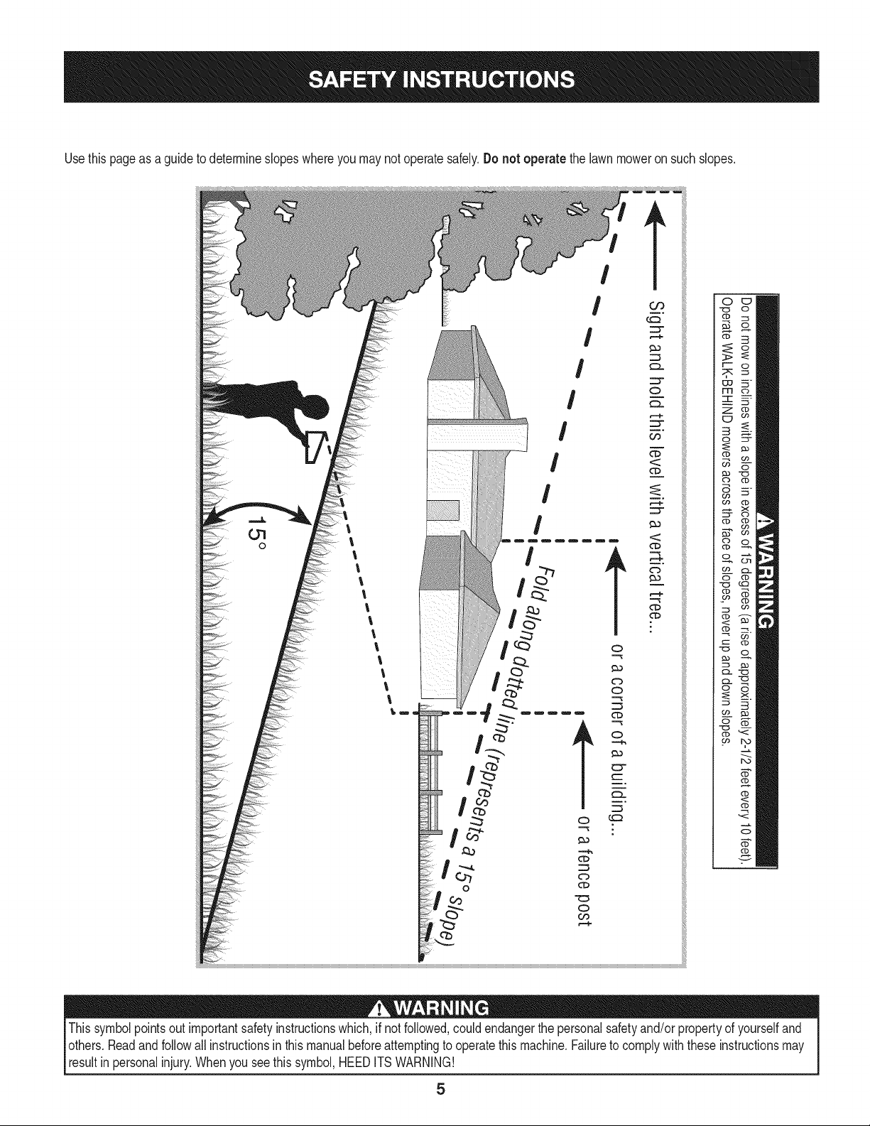
Usethis pageas a guideto determineslopeswhereyoumay not operatesafely.Do not operate the lawnmoweron suchslopes.
!
l
I
I
!
!
!
Thissymbolpointsoutimportantsafetyinstructionswhich,ifnot followed,could endangerthe personalsafetyand/or propertyof yourselfand
others.Readandfollow all instructionsinthis manualbeforeattemptingto operatethis machine.Failureto complywith these instructionsmay
resultinpersonalinjury.Whenyou seethis symbol,HEEDITSWARNING!

WARNING
This symbol points out important safety instructions
which, if not followed, could endanger the personal
safety and/or property of yourself and others. Read and
follow all instructions in this manual before attempting
to operatethis machine. Failureto comply with these
instructions may result in personal injury. When you see
this symbol HEED ITS WARNING!
Your Responsibility
Restrictthe use of this power machine to persons who
read, understand, and follow the warnings and instruc-
tions in this manualand on the machine.
6

Thispageleftintentionallyblank.
7
IMPORTANT:Thisunitis shippedwithoilin the engine.After
assembly,see page12for fuelandoil details.
IMPORTANT:Referenceto rightor leftside of the moweris observed
fromthe operatingposition.
The mowingdeck is capableof throwingobjects.Failureto operate
the mowerwithoutthe dischargechute in the properoperatingposi-
tion couldresultinseriouspersonalinjuryand/or propertydamage.
Disconnectthe sparkplugwire andgroundit againstthe engineto
preventunintendedstarting.
LOOSE PARTS IN CARTON
Thefollowingitemsare packagedin a bag:
Operator'sManual,Oildrain hose,Waterhosecoupler,EngineManual
TOOLS NEEDED FOR ASSEMBLY
A setof adjustablewrenchesand tiregauge
REMOVING THE UNIT FROM THE CRATE
1. Cut straps,if present,securingunit to pallet.Leaveuniton pallet
duringhandleassembly.
2. Removeany protectivepackagingand plastictie straps.
3. Use thedeck heightlever(see "Knowyour Mower"section)to
raisethe cuttingdeckto itshighestposition.
ASSEMBLING THE HANDLE
1. Removelowerstar knobsand carriagescrewsfrom lowerhandle,
Figure1.
Figure1
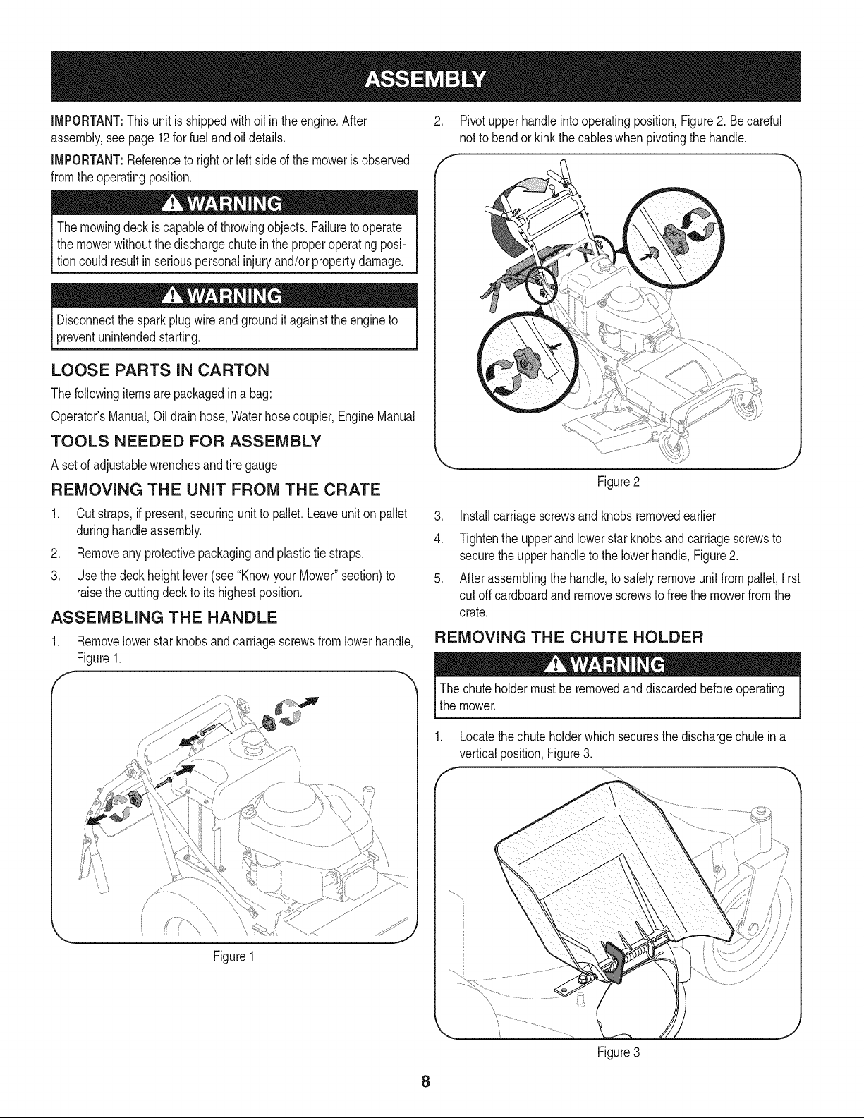
2. Pivotupperhandleinto operatingposition,Figure2. Be careful
not to bendorkinkthe cableswhen pivotingthe handle.
J
Figure2
3. Installcarriagescrewsand knobsremovedearlier.
4. Tightenthe upperand lowerstar knobs and carriagescrewsto
securethe upperhandleto the lowerhandle,Figure2.
5. After assemblingthe handle,to safelyremoveunitfrompallet,first
cut offcardboardand removescrewsto free the mowerfromthe
crate.
REMOVING THE CHUTE HOLDER
The chuteholdermustbe removedanddiscardedbeforeoperating
the mower.
1. Locatethe chuteholderwhich securesthe dischargechutein a
verticalposition,Figure3.
f
8
Figure3
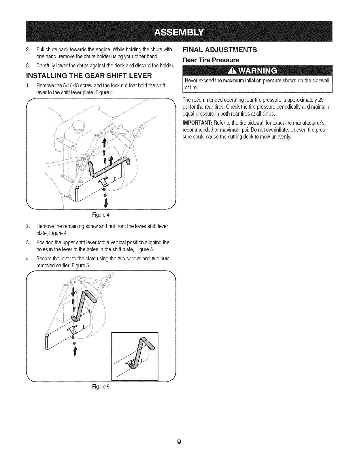
2. Pullchutebacktowardstheengine.Whileholdingthechutewith
onehand,removethechuteholderusingyourotherhand.
3. Carefullylowerthechuteagainstthedeckanddiscardtheholder.
INSTALLING THE GEAR SHIFT LEVER
1. Removethe5/16-18screwand the lock nutthat hold the shift
leverto the shiftleverplate,Figure4.
f
4
/
Figure4
J
2. Removethe remainingscrewand nutfrom the lowershift lever
plate,Figure4.
3. Positionthe uppershift leverinto a verticalpositionaligningthe
holesin the leverto the holesin the shiftplate,Figure5.
4. Securethe leverto the plateusingthe two screwsand two nuts
removedearlier,Figure5.
FINAL ADJUSTMENTS
Rear Tire Pressure
Neverexceedthe maximuminflationpressureshownon thesidewall
of tire.
The recommendedoperatingreartire pressureis approximately20
psifor the reartires.Checkthe tire pressureperiodicallyand maintain
equalpressurein both reartiresat all times.
IMPORTANT:Referto the tire sidewallfor exacttire manufacturer's
recommendedormaximumpsi. Donot overinflate.Uneventirepres-
surecouldcausethe cuttingdeckto mowunevenly.
/
Figure5
9

f
Throttle/Choke Blade
ControlLever Control
GasCap
_--. Deck
Height
Lever
DriveControl
GearShift Lever
Figure6
Befamiliarwithall the controlsandtheir properoperation.Knowhow
to stopthe machineand disengagethe controls.
Theoperationof any lawnmowercan resultin foreignobjectsbeing
thrownintothe eyes,whichcan damageyoureyesseverely.Always
wearsafetyglasseswhileoperatingthe mower,orwhile performing
anyadjustmentsor repairson it.
THROTTLE/CHOKE CONTROL LEVER
iMPORTANT:Whenoperatingthe mowerwith the
cuttingdeckengaged,be certainthat the throttle/
chokecontrolleveris alwaysinthe fast position.
Thisleveris usedto adjustenginespeeds,to apply
theenginechoke,and to stop the engine.Always
runengineat fast speedsettingfor bestmower
performance.
CHOKE: Usewhenstartinga coldengine
FAST:Useduringmoweroperation.
SLOW:Usewhen idlingengine.
STOP:Stopsthe engine.
Choke Fast Slow/Idle
EngineOff
Besureno one otherthan theoperatoris standingnearthe lawn
mowerwhilestartingengineoroperatingmower.Neverrun engine
indoorsorin enclosed,poorlyventilatedareas.Engineexhaust
containscarbonmonoxide,an odorlessand deadlygas. Keep hands,
feet, hairand looseclothingawayfrom any movingpartson engine
andlawn mower.
GAS CAP
Removethe gascap to addfuel to the fueltank.
Useclean,fresh, regularunleadedgasolinewith a minimumof 85
octane.
Turntheengineoff and let the enginecool at leasttwo minutes
beforeremovingthe gascap.
DECK HEIGHT LEVER
Usethis leverto adjustthecuttingheight.To use,move
the leverto the left, thenplacethe leverinthe notchbest
suitedfor yourapplication.
10
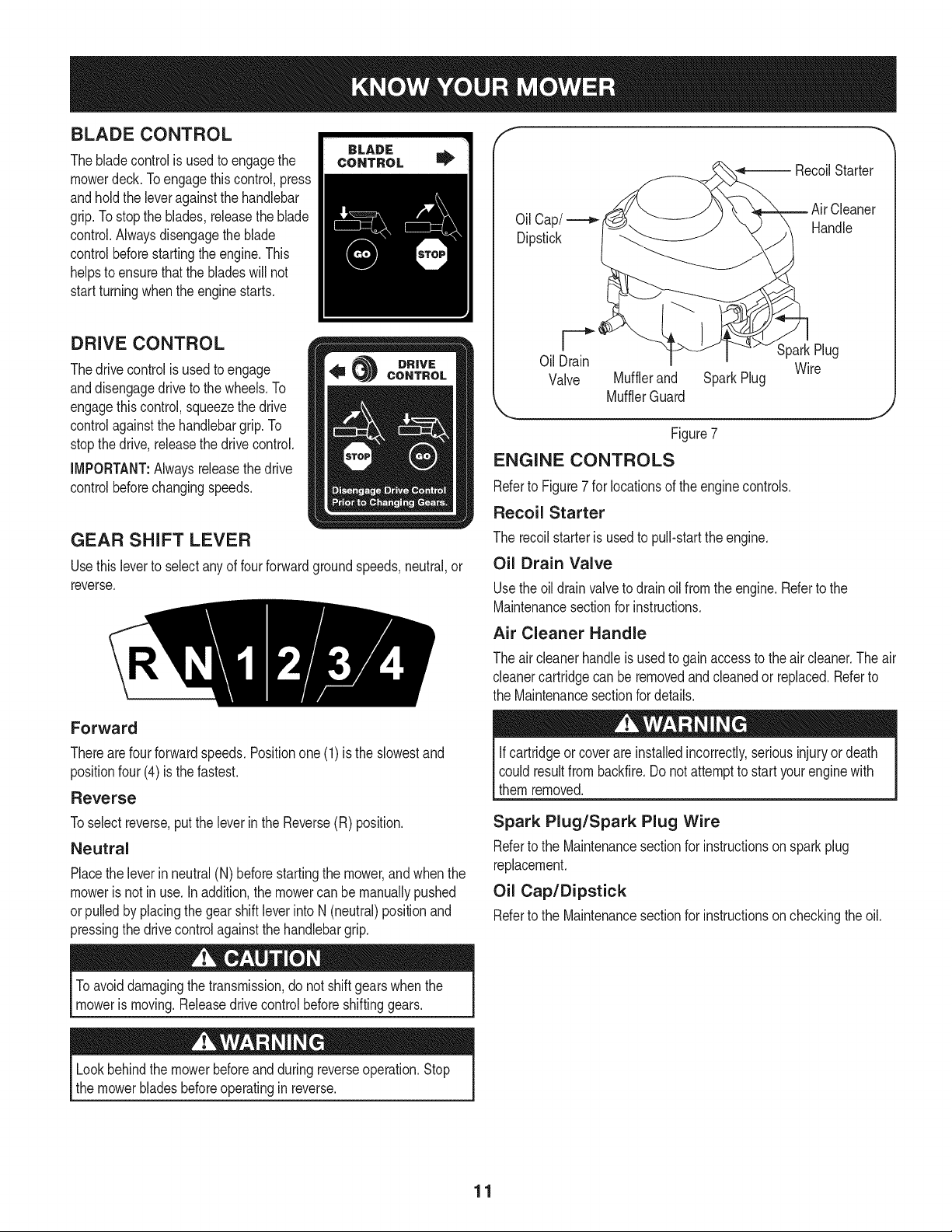
BLADE CONTROL
Thebladecontrolis usedto engagethe
mowerdeck.Toengagethiscontrol,press
andhold the leveragainstthe handlebar
grip.Tostopthe blades,releasethe blade
control.Alwaysdisengagethe blade
controlbeforestartingthe engine.This
helpsto ensurethatthe bladeswill not
startturningwhenthe enginestarts.
DRIVE CONTROL
Thedrivecontrolis usedto engage
anddisengagedriveto thewheels.To
engagethiscontrol,squeezethe drive
controlagainstthe handlebargrip.To
stopthedrive, releasethe drivecontrol.
IMPORTANT:Alwaysreleasethe drive
controlbeforechangingspeeds.
GEAR SHIFT LEVER
Usethis leverto selectanyof four forwardgroundspeeds,neutral,or
reverse.
Oil Cap/
Dipstick
RecoilStarter
Cleaner
Handle
OilDrain
Valve Mufflerand SparkPlug
MufflerGuard
SparkPlug
Wire
Figure7
ENGINE CONTROLS
Referto Figure7for locationsof the enginecontrols.
Recoil Starter
The recoilstarteris usedto pull-startthe engine.
Oil Drain Valve
Usethe oil drainvalveto drainoil fromthe engine.Referto the
Maintenancesectionfor instructions.
Air Cleaner Handle
Theaircleanerhandleis usedto gainaccessto theair cleaner.The air
cleanercartridgecan beremovedandcleanedor replaced.Referto
the Maintenancesectionfor details.
Forward
Therearefourforwardspeeds.Positionone (1) is the slowestand
positionfour(4) is thefastest.
Reverse
Toselectreverse,putthe leverin the Reverse(R) position.
Neutral
Placethe leverinneutral(N) beforestartingthe mower,andwhen the
moweris not inuse.In addition,the mowercan be manuallypushed
orpulledby placingthe gearshiftleverinto N (neutral)positionand
pressingthe drivecontrolagainstthe handlebargrip.
Ifcartridgeor coverare installedincorrectly,seriousinjuryor death
could resultfrombackfire.Donot attemptto startyourenginewith
them removed.
Spark Plug/Spark Plug Wire
Referto the Maintenancesectionfor instructionson sparkplug
replacement.
Oil Cap/Dipstick
Referto the Maintenancesectionfor instructionson checkingtheoil.
To avoiddamagingthe transmission,do notshift gearswhenthe
mowerismoving.Releasedrive controlbeforeshiftinggears.
Lookbehindthe mowerbeforeandduring reverseoperation.Stop
the mowerbladesbeforeoperatingin reverse.
11
Theoperationof any lawnmowercan resultin foreignobjectsbeing
thrownintothe eyes,whichcan damageyoureyesseverely.Always
wearsafetyglasseswhileoperatingthe mower,orwhile performing
anyadjustmentsor repairson it.
Useextremecarewhenhandlinggasoline.Gasolineis extremely
flammableandthe vaporsareexplosive.Neverfuel machineindoors
orwhilethe engineis hotor running.Extinguishcigarettes,cigars,
pipes,andothersourcesof ignition.
GAS AND OIL FILL-UP
Gas Fill
Useof Alcoholblendedfuels(calledgasoholor usingethanolor
methanol)canattract moisturewhich leadsto separationand forma-
tionof acidsduringstorage.Acidicgascan damagethe fuel system
of anenginewhilein storage.
To avoidengineproblems,the fuel systemshouldbeemptiedbefore
storagefor 30 daysor longer.Drainthe gastank, startthe engine
and let it rununtil thefuel linesandcarburetorare empty. Usefresh
Ifuel nextseason.SeeSTORAGEInstructionsfor additionalinforma-
[tion.
)ermanentdamagemayoccur.
IMPORTANT:Themowerisshippedwithoutgas inthe fuel tank.
• Neverfill the fueltankcompletely.Fill thetankto no morethan
1/2-inchbelowbottomof filler neckto providespacefor fuel
expansion.
• Alwaysuseclean,fresh,unleadedgradeautomotivegasoline.
Fillthe fuel tankoutdoorsand usea funnelor spoutto prevent
spilling.Makesurethatthe containerfromwhichyoupourthe
gasolineis cleanandfree fromrustorotherforeignparticles.
Makesureto wipe offany spilledfuel beforestartingthe engine.
• At the endof thejob, emptythe fueltankif the moweris not
goingto beusedfor 30 days or longer.Storegasolinein a clean
containerand keepthe cap in placeon the container.See STOR-
AGEinstructionsforadditionalinformation.
Besure noone otherthanthe operatoris standingnearthe lawn
mowerwhile startingengineor operatingmower.Neverrunengine
indoorsor inenclosed,poorlyventilatedareas.Engineexhaust
containscarbonmonoxide,anodorlessand deadlygas. Keephands,
feet,hair,andlooseclothingawayfrom anymovingparts
Oil Fill
IMPORTANT:The mowerisshippedwithmotoroil intheengine;
however,you MUSTcheckthe oil levelbeforeoperating.Oil shouldbe
changedonce afterthe first twohoursof operationandevery25 hours
of operationthereafter.Usethe grade of engineoil specifiedin the
Maintenancesection.
.
2.
Removethe oilfill cap/dipstickfromtheoil fill tube.
Checkthatthe levelof oil is upto the FULLmarkonthe dipstick.
Ifneeded,pouroil slowlyintothe oilfill tube untila FULLoil level
is achieved.
3. Replacetheoil fill cap/dipstick.
STARTING THE MOWER
1. Releaseallcontrolsonthe mowerto preventwheelsor blades
fromrotating.
2. Movegearshift leverto neutral(N) position.
3. Movethethrottle/chokecontrolleverfullyupwardto choke setting
I',1to starta cold engineor to fast (rabbit)setting_ to starta
warmengine.
4. To startengineusing recoilstarter:
a. Standon left side (as viewedfrombehindhandlebars)of ma-
chine.Be sureyourfeet are safelyawayfrom the underside
of the mowerdeckandall mowercontrolsare released.
b. Graspstarterrope handleand pull slowlyuntil ropepulls
slightlyharder.Let roperewindslowly.Thenpullropewitha
rapid,full arm stroke.Let ropereturnslowly.Ifenginefailsto
start afterthreepulls,repeatinstructions(try settingthrottle
at fast setting).
c. Whenengine starts,operatein fast throttlesetting_lf
(movethrottle/chokecontrol leverfrom chokesettingto fast
setting).
Lookbehindthe mowerbeforeandduring reverseoperation.Stop
the mowerbladesbeforeoperatingin reverse.
Ifyou strikea foreignobject,stoptheengine.Removewire fromthe
sparkplug,thoroughlyinspectmowerforany damage,and repair
damagebeforerestartingandoperating.Extensivevibrationof
mowerduringoperationis an indicationof damage.Theunit should
bepromptlyinspectedandrepaired.
12
Lookbehindthe mowerbeforeandduring reverseoperation.Stop
the mowerbladesbeforeoperatingin reverse.
USING THE MOWER
IMPORTANT:Alwaysreleasethe drivecontrolbeforechanging
speeds.Referto "Knowyour Mower"sectionfor mowercontroldetails.
Besure lawnis clearof stones,sticks,wire,orotherobjectswhich
coulddamagelawnmoweror engine.Suchobjectscouldbeaccidently
thrownby themowerin anydirectionandcause seriouspersonalinjury
to the operatorandothers.Forbestresults,do not cut wet grass and
nevercut off morethan one-thirdof the totallengthof the grass.
1. Oncethe engineis running,slowlysqueezethe drivecontrol
againstthe upperhandleto propeltheunit. Toactivatethe cutting
blades,squeezethe bladecontrolagainstthe upper handle.
2. Tochangegears, releasethe drivecontrolleverandmovethe
gearshiftleverto the desiredsetting.Whenfirst practicingwith
the mower,put the leverin No.1position.Selectforwardspeeds
accordingto mowingconditionsand terrain.Use slowerspeeds
on roughterrainor whengrassis heavyor thick.The forward
speedcanbe increasedon smoothterrainor if the grass coveris
light.Allowthewheelsto stopcompletelybeforeshiftingfrom one
speedintoanother.
IMPORTANT:Beawarethatwhenengagingthedrive control
leverwiththe gearshift leverin 3rd or 4th gear,the powerand
torquegeneratedmaycausethe unitto lurchforward.Toavoid
this,slowlysqueezethe drivecontrolleveragainstthe upper
handle.
.
Tostopthe blades,releasethe bladecontrol.To stopthe drive
controlto the wheels,releasethe drivecontrol.
STOPPING THE MOWER
.
2.
Releasebladeanddrivecontrolto stopwheelsand deck blades.
Movethrottle/chokecontrolleverdownto slow (turtle)
position.Wheneverpossible,graduallyreduceenginespeed
beforestoppingengine.
3. Movethrottle/chokecontrolleverallthe way downto stop
position.
4. Disconnectsparkplug wirefrom sparkplug and groundagainst
the engine.
MOVING THE MOWER WITHOUT
ENGINE POWER
Themowercan bemanuallypushedor pulledby placingthe gearshift
leverinto N (neutral)positionandpressingthe drivecontrolagainstthe
handlebargrip.
MULCHING OR SIDE-DISCHARGE MOWING
Youcanuse the mowereitheras a mulchingmoweror as a side-
dischargemower.To usethe mulchingfeature,insert the mulchplug
as describedbelow.Removethe mulchplugto side-dischargegrass
clippings.
The mulchplugis designedto keepthe dischargechute raisedup
while mowing.Whenthe plugis removed,the dischargechute will
loweritselffor side-dischargemowing.
Beforeinstallingor removingmulch plug,stopengine,wait for parts
to stopmoving,and disconnectsparkplugwire.
To installor removemulch plug:
1. Stoptheengineand wait for all parts to stop moving.
2. Disconnectthe sparkplug wirefrom the sparkplug.
Figure8
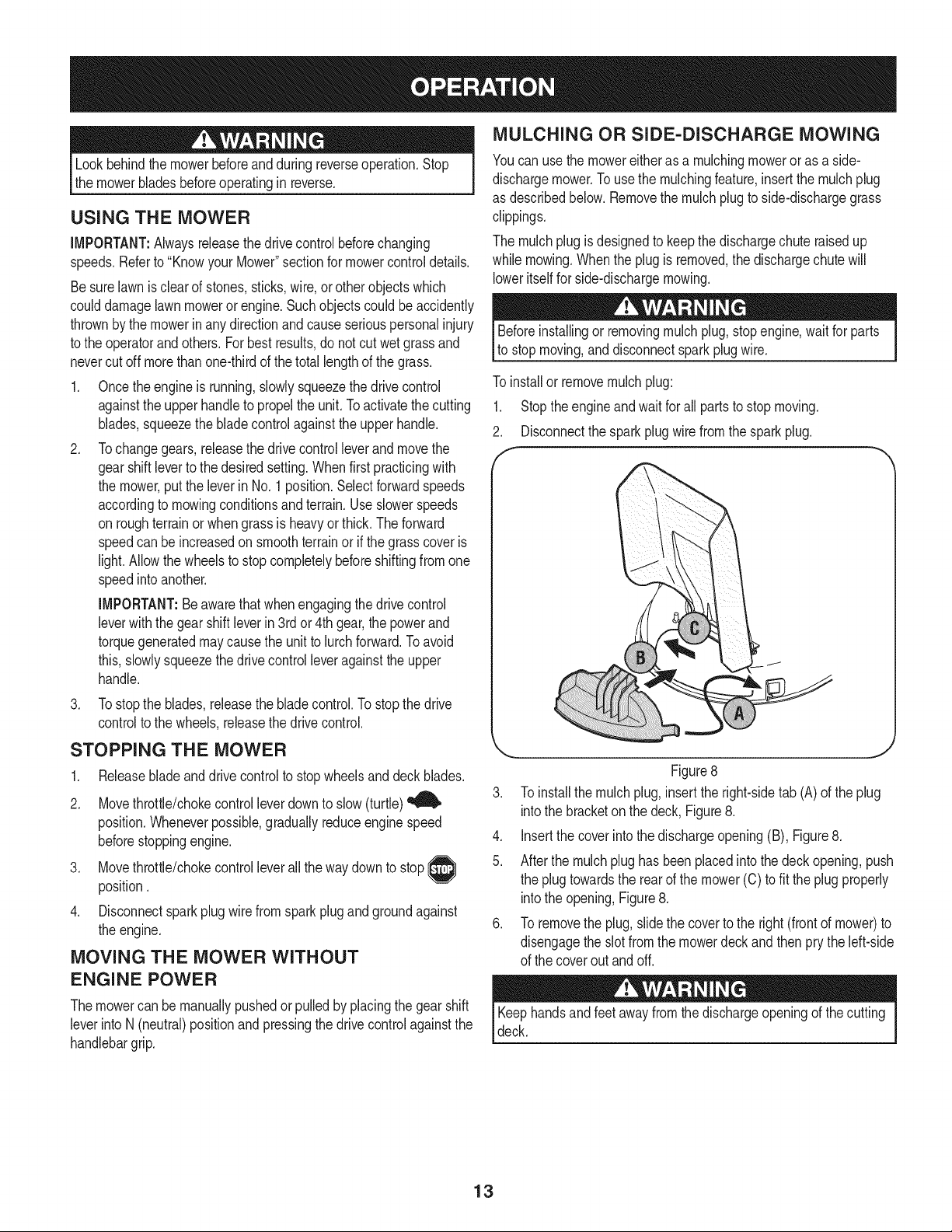
3. To installthe mulchplug,insertthe right-sidetab (A)of the plug
intothe bracketonthe deck, Figure8.
4. Insertthe cover intothe dischargeopening(B), Figure8.
5. After the mulchplug has been placedinto thedeck opening,push
the plugtowardsthe rearof the mower(C) tofit the plugproperly
intothe opening,Figure8.
6. To removethe plug,slidethe coverto the right(frontof mower)to
disengagethe slotfromthe mowerdeckand then prythe left-side
of the coverout andoff.
Keephandsandfeet awayfrom thedischargeopeningof the cutting
deck.
13
Alwaysstopengine,disconnectsparkplug,andgroundagainst
enginebeforeperforminganytypeof maintenanceonthe mower.
GENERAL RECOMMENDATIONS
Alwaysobservesafetyruleswhenperformingany type of
maintenanceon the mower.
Thewarrantyon thislawnmowerdoesnot coveritemsthathave
beensubjectedto operatorabuseor negligence.To receivefull
valuefromwarranty,operatormustmaintainthe lawnmoweras
instructedin this manual.
• Changingof engine-governedspeedwill voidenginewarranty.
• Alladjustmentsshouldbe checkedat least onceeach season.
• Periodicallycheckall fastenersand makesuretheyare tight.
ENGINE MAINTENANCE
Checking the Spark Plug
Cleansparkplugand reset theelectrodegap to 0.030"at leastoncea
season;replaceevery100hoursof operation.
1. Cleanareaaroundthe spark plug base.Do not sandblastspark
plug.Sparkplugshouldbe cleanedby scrapingor wire brushing
andwashingwitha commercialsolvent
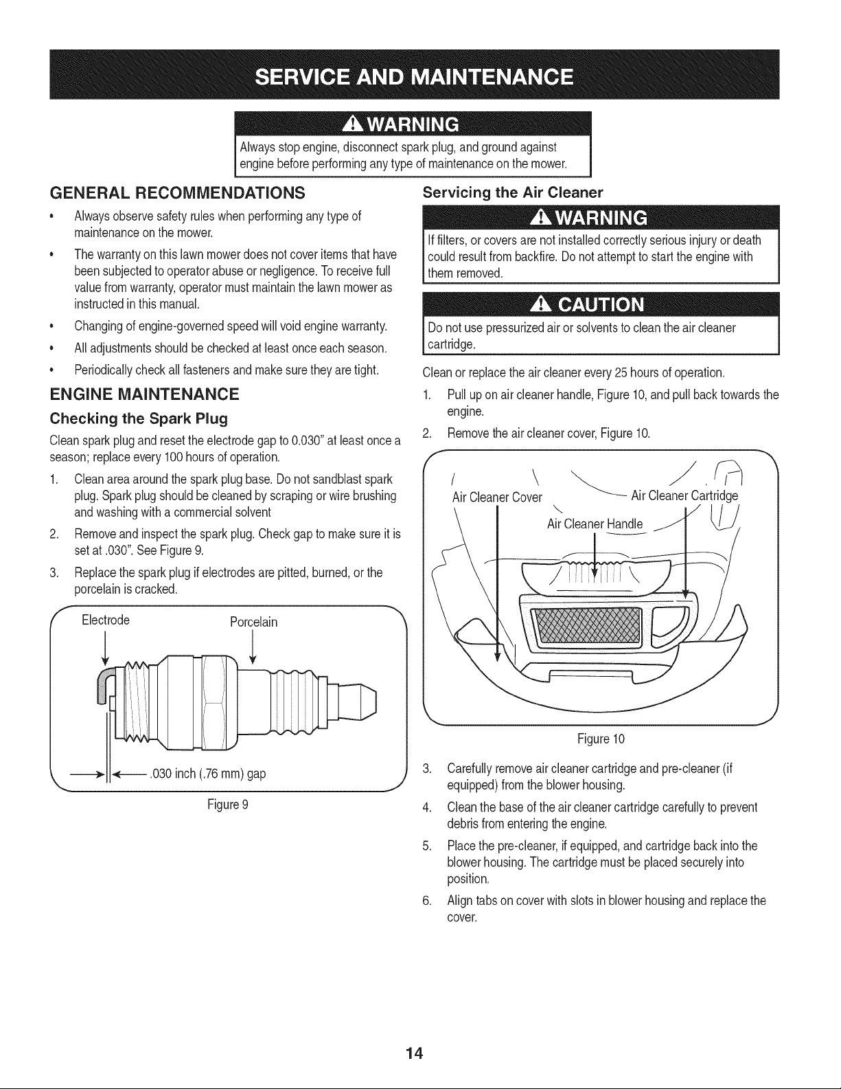
2. Removeand inspectthe spark plug.Checkgap to makesureit is
setat .030".See Figure9.
3. Replacethe sparkplugif electrodesarepitted,burned,or the
porcelainis cracked.
Electrode
l
Porcelain
.030inch (.76ram)gap
Figure9
J
Servicing the Air Cleaner
Iffilters,or coversare notinstalledcorrectlyseriousinjuryordeath
could resultfrombackfire.Do notattemptto startthe enginewith
themremoved.
Donot use pressurizedairor solventsto cleantheair cleaner
cartridge.
Cleanor replacethe aircleanerevery25 hoursof operation.
1. Pull up on air cleanerhandle,Figure10,and pull back towardsthe
engine.
Removethe aircleanercover,Figure10.
.
f
Air CleanerCover Air CleanerCartridge
\
AirCleanerHandle
Figure10
3. Carefullyremoveair cleanercartridgeand pre-cleaner(if
equipped)fromthe blowerhousing.
4. Cleanthe baseof the air cleanercartridgecarefullyto prevent
debrisfromenteringthe engine.
5. Placethe pre-cleaner,if equipped,and cartridgeback into the
blowerhousing.The cartridgemustbe placedsecurelyinto
position.
6. Align tabs on cover with slotsin blowerhousingand replacethe
cover.
14
Changing the Engine Oil
Theoil inthe engineshouldbe changedevery25 hoursof operation.
1. Togain accessto the oil drain valveon the engine,the right
handlebracetube shouldbe pivotedforward.
a. Removetheupper star knoband carriagescrewon the right
sideof the handle,Figure11.
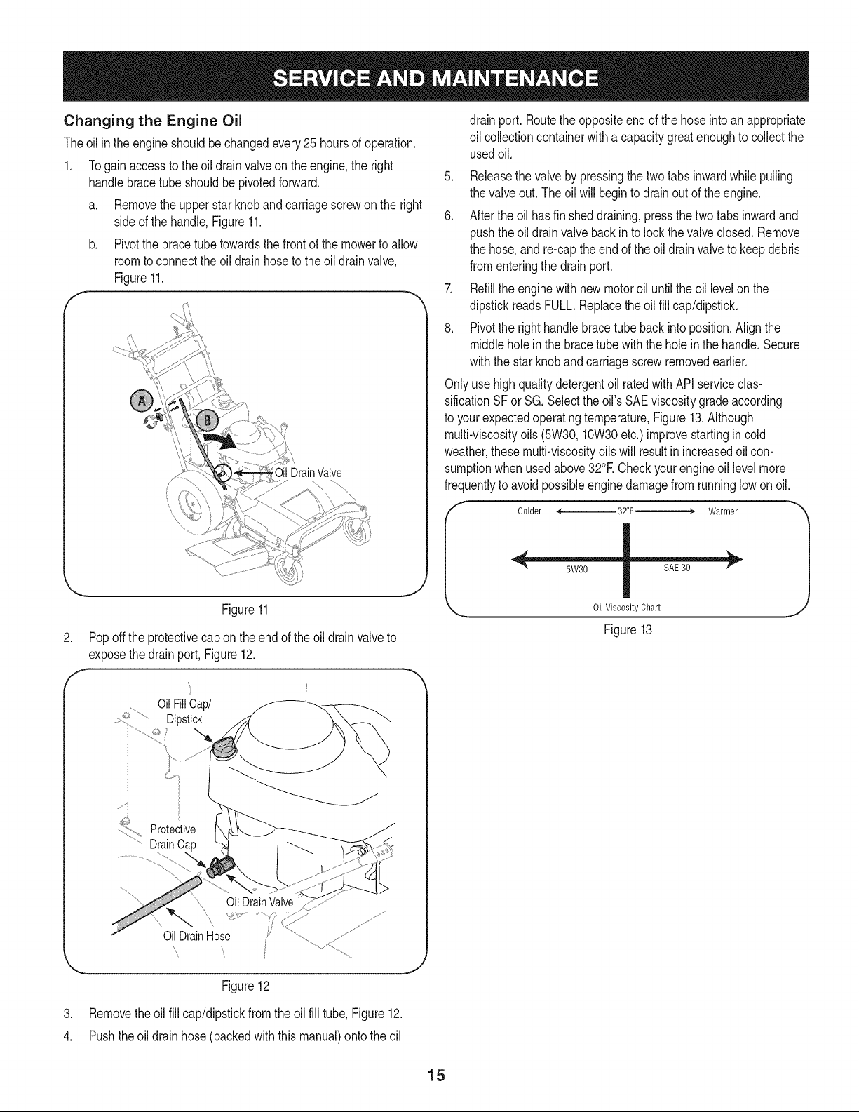
b. Pivotthe bracetubetowardsthe front of the mowerto allow
roomto connectthe oil drainhoseto theoil drainvalve,
Figure11.
\\
DrainValve
Figure
2. Pop off the protectivecap onthe endof the oil drainvalveto
exposethedrainport, Figure12.
F
OilFillCap/
_':.............Dipstick
_::;> Protective
......DrainCap
drainport. Routethe oppositeendof the hoseintoan appropriate
oil collectioncontainerwith a capacitygreatenoughto collectthe
usedoil.
5. Releasethe valveby pressingthe two tabs inwardwhilepulling
the valveout.The oil willbeginto drainoutof the engine.
6. After the oil hasfinisheddraining,pressthe two tabs inwardand
pushthe oil drainvalvebackinto lockthe valveclosed. Remove
the hose,and re-captheendof the oil drainvalveto keepdebris
fromenteringthe drainport.
7. Refillthe enginewith newmotoroil untilthe oil levelon the
dipstickreadsFULL.Replacetheoil fill cap/dipstick.
8. Pivotthe righthandlebracetube backinto position.Align the
middleholein the bracetube withthe holeinthe handle.Secure
withthe starknobandcarriagescrewremovedearlier.
Onlyusehighquality detergentoil ratedwithAPI serviceclas-
sificationSF or SG. Selectthe oil'sSAE viscositygradeaccording
to yourexpectedoperatingtemperature,Figure13.Although
multi-viscosityoils(5W30,10W30etc.) improvestartingin cold
weather,thesemulti-viscosityoils will resultin increasedoil con-
sumptionwhenusedabove32°E Checkyourengineoil levelmore
frequentlyto avoidpossibleenginedamagefrom runninglowon oil.
I
Colder <------_ 32°F > Warmer
Oil Viscosity Chart
Figure 13
1
................::_
Figure12
J
3. Removetheoil fill cap/dipstickfromthe oil fill tube,Figure12.
4. Pushtheoil drain hose(packedwith this manual)ontothe oil
15
Beforeperforminganytype of maintenanceon the machine,wait for
allpartsto stopmovingand disconnectthe sparkplugwire.Failure
I to followthisinstructioncould resultin personalinjuryor property
[damage.
REMOVING THE BELT COVER
The beltcovermustbe removedto performseveralmaintenanceand
serviceprocedures.Followtheinstructionsbelowto removethe belt
cover.
1. Stopengine,wait for all partsto stop moving,and disconnect
sparkplugwire.
2. Removethe three screwsandwashersholdingthe coverto the
frame,Figure14.
Figure14
3. Removethe beltcover.
4. To reinstallthe beltcover,placethe coverinpositionandfasten
usingthreescrewsandwashersremovedearlier.
Do notoperateunit withoutbeltcoverinstalled.Failureto followthis
instructioncouldresult in personalinjuryor propertydamage.
REMOVING THE MOWER DECK
Whenservicingthe undersideof the mowerdeck for any reason,the
cuttingdeckshouldfirst be removed.Followthe instructionsbelowto
removethe cuttingdeck:
1. Stopthe engine,wait for all partsto stopmoving,and disconnect
sparkplugwire.
2. Releaseall mowercontrols.
3. Removebeltcoveras instructedunder"Removingthe
Belt Cover."
4. Use thedeck heightleverto movethe cuttingdeck to its
highestposition.
5. Placesmallwoodenblocksunderthedeck.
6. Use thedeck heightleverto lowerthe deck sothat it restsupon
thewoodenblocks.
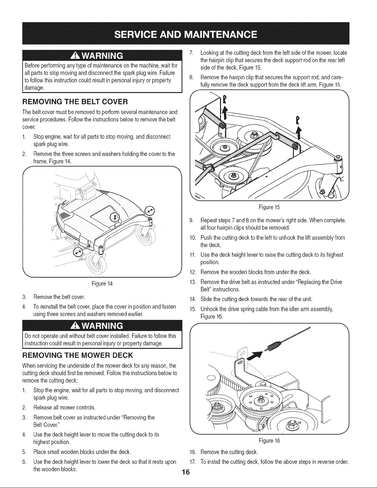
7. Lookingat thecuttingdeck from the left side of the mower,locate
the hairpinclip thatsecuresthe decksupportrodon the rearIdt
side of the deck,Figure15.
8. Removethe hairpinclip that securesthe supportrod,and care-
fully removethedeck supportfromthe deck lift arm, Figure15.
Figure15
9. Repeatsteps7 and8 onthe mower'srightside.Whencomplete,
all fourhairpinclipsshouldbe removed.
10. Pushthe cuttingdeck to the left to unhookthe lift assemblyfrom
the deck.
11.
12.
13.
Usethe deckheightleverto raisethecuttingdeckto its highest
position.
Removethe woodenblocksfromunderthe deck.
Removethe drivebelt as instructedunder"Replacingthe Drive
Belt"instructions.
14. Slidethe cuttingdecktowardsthe rearof the unit.
15. Unhookthe drivespringcablefromthe idlerarm assembly,
Figure16.
f
16.
17.
16
J
Figure16
Removethe cuttingdeck.
To installthe cuttingdeck,followthe abovestepsin reverseorder.
Beforeperforminganytypeofmaintenanceonthemachine,waitfor
allpartstostopmovinganddisconnectthesparkplugwire.Failure
tofollowthisinstructioncouldresultinpersonalinjuryorproperty
damage.
LUBRICATION
Pivot Points & Linkage
Lubricateall the pivotpointson thedrive systemand lift linkageat
leastoncea season,or every 25 hoursof operation,withlight oil.
Rear Wheels
The rearwheelsshouldbe removedfromthe axlesoncea season.
Lubricatethe axles and the rimswell with an all-purposegreasebefore
reinstallingthem.
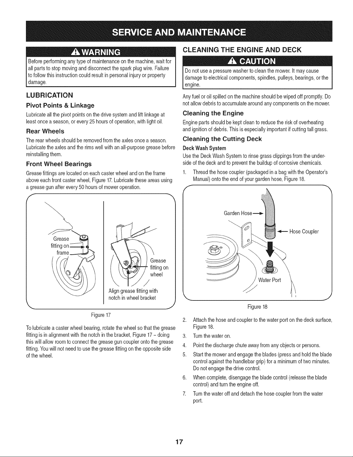
Front Wheel Bearings
Greasefittingsare locatedon eachcasterwheeland on the frame
aboveeach frontcasterwheel,Figure17.Lubricatetheseareasusing
a greasegunafter every50 hoursof moweroperation.
F
Grease
fittingon
wheel
/
Aligngreasefittingwith
notchin wheelbracket
Figure17
Tolubricateacasterwheelbearing,rotatethe wheelso thatthe grease
fittingis inalignmentwiththe notchinthe bracket,Figure17- doing 3.
thiswill allowroomto connectthe greaseguncouplerontothe grease 4.
fitting.Youwill notneedto usethe greasefittingonthe oppositeside
of the wheel. 5.
CLEANING THE ENGINE AND DECK
Donot usea pressurewasherto cleanthe mower.It maycause
damageto electricalcomponents,spindles,pulleys,bearings,or the
engine.
Any fuelor oil spilledon the machineshouldbe wipedoff promptly.Do
notallowdebristo accumulatearoundany componentson the mower.
Cleaning the Engine
Engineparts shouldbe kept cleanto reducethe risk of overheating
and ignitionof debris.Thisis especiallyimportantif cuttingtallgrass.
Cleaning the Cutting Deck
DeckWash System
Usethe DeckWashSystemto rinsegrassclippingsfromthe under-
sideof the deckandto preventthe buildupof corrosivechemicals.
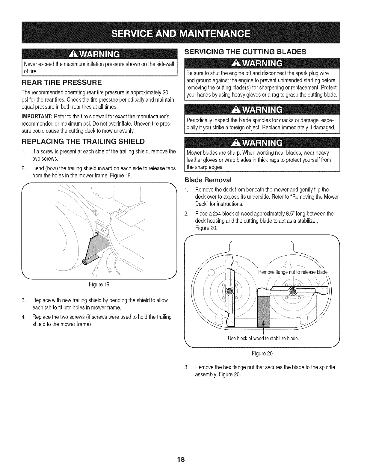
1. Threadthe hosecoupler(packagedin a bagwith the Operator's
Manual)onto the endof yourgardenhose,Figure18.
GardenHose_
HoseCoupler
WaterPort
/y
Figure18
Attachthe hoseandcouplerto thewater porton thedeck surface,
Figure18.
Turnthewateron.
Pointthe dischargechute awayfromany objectsor persons.
Startthe mowerandengagethe blades(press and hold the blade
controlagainstthe handlebargrip) for a minimumof two minutes.
Donot engagethedrive control.
Whencomplete,disengagethe bladecontrol(releasethe blade
control)andturn the engineoff.
Turnthewateroffand detach thehose couplerfrom the water
port.
17
Neverexceedthe maximuminflationpressureshownon the sidewall
of tire.
REAR TIRE PRESSURE
The recommendedoperatingreartire pressureisapproximately20
psi forthe reartires.Checkthe tire pressureperiodicallyandmaintain
equalpressurein bothreartiresat all times.
IMPORTANT:Referto the tire sidewallfor exacttire manufacturer's
recommendedor maximumpsi.Do notoverinflate.Uneventire pres-
surecouldcausethe cuttingdeckto mowunevenly.
REPLACING THE TRAILING SHIELD
.
Ifa screwis presentat each sideof the trailingshield,removethe
twoscrews.
Bend(bow)the trailingshieldinwardon eachside to releasetabs
fromthe holesin the mowerframe,Figure19.
.
.
\_ ii
Figure19
Replacewith newtrailingshieldbybendingthe shieldto allow
eachtab to fit intoholesin mowerframe.
Replacethe two screws(if screwswere usedto holdthetrailing
shieldto the mowerframe).
SERVICING THE CUTTING BLADES
Besureto shutthe engineoff and disconnectthe sparkplugwire
andgroundagainsttheengineto preventunintendedstartingbefore
removingthecutting blade(s)for sharpeningor replacement.Protect
yourhandsby usingheavyglovesora ragto graspthe cuttingblade.
Periodicallyinspectthe bladespindlesfor cracks or damage,espe-
ciallyif you strikeaforeignobject.Replaceimmediatelyif damaged.
Mowerbladesare sharp.Whenworkingnearblades,wearheavy
leatherglovesorwrap bladesin thick ragsto protectyourselffrom
the sharpedges.
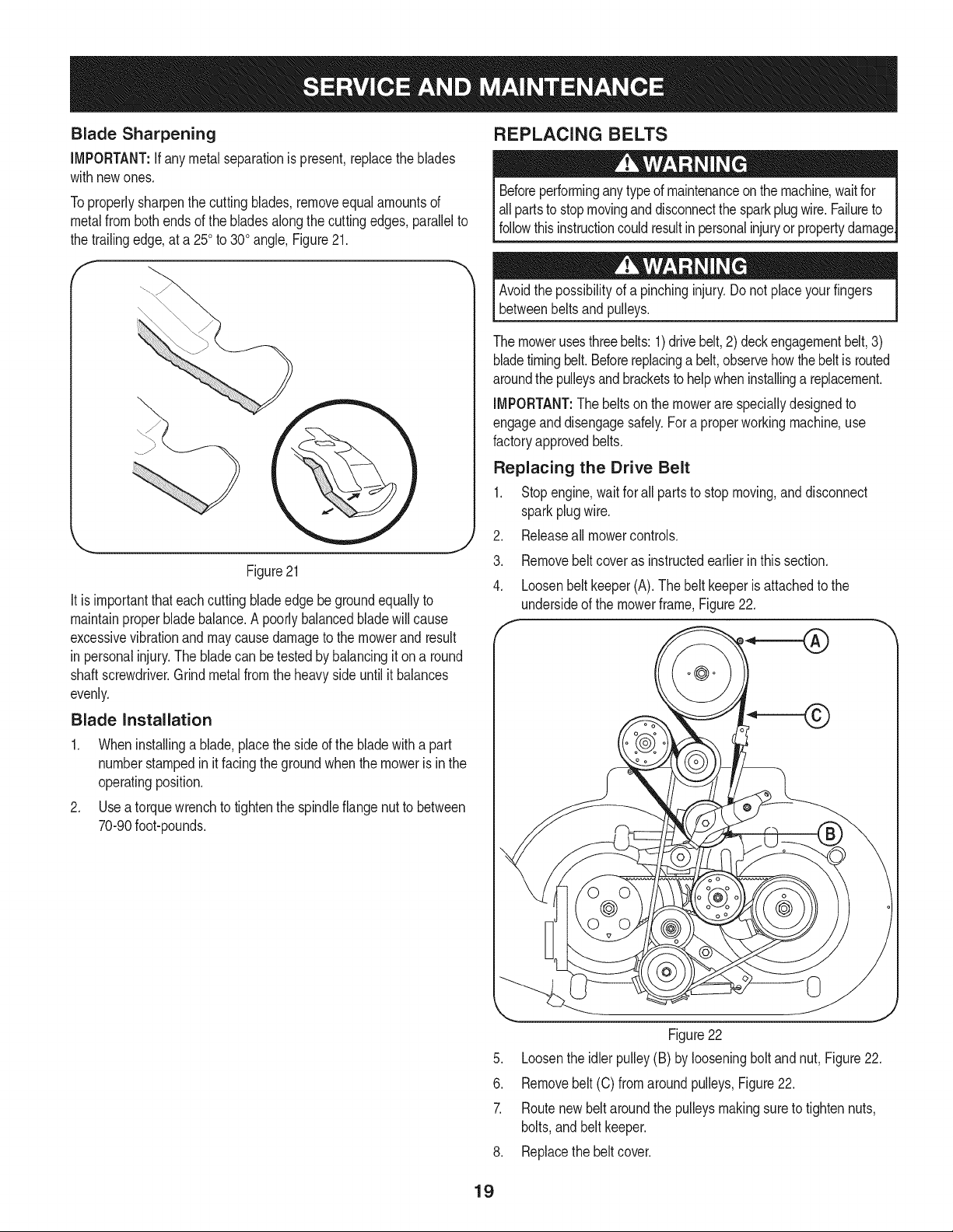
Blade Removal
F
.
Removethe deckfrombeneaththe mowerandgentlyflip the
deckoverto exposeits underside.Referto "Removingthe Mower
Deck"for instructions.
Placea 2x4 blockof woodapproximately8.5"longbetweenthe
deckhousingand the cuttingblade to act as a stabilizer,
Figure20.
\
Removeflangenutto releaseblade
Useblockofwoodtostabilizeblade.
Figure20
J
3. Removethe hexflangenut that securesthe bladeto the spindle
assembly,Figure20.
18
Blade Sharpening
iMPORTANT:If any metal separationis present,replacethe blades
withnewones.
Toproperlysharpenthe cuttingblades,removeequal amountsof
metalfrombothends of the bladesalongthecuttingedges,parallelto
the trailingedge,at a 250to 300angle, Figure21.
J
Figure21
It is importantthateachcuttingbladeedge begroundequallyto
maintainproper bladebalance.A poorlybalancedblade willcause
excessivevibrationandmaycause damageto the mowerand result
in personalinjury.Thebladecan betestedbybalancingit on a round
shaftscrewdriver.Grindmetalfrom the heavyside untilit balances
evenly.
Blade Installation
1. Wheninstallinga blade,placethe sideof the bladewitha part
numberstampedin it facingthegroundwhenthe moweris in the
operatingposition.
2. Use a torquewrenchto tightenthe spindleflangenutto between
70-90foot-pounds.
REPLACING BELTS
Beforeperforminganytypeof maintenanceonthemachine,waitfor
allpartsto stopmovinganddisconnectthe sparkplugwire. Failureto
followthisinstructioncouldresultinpersonalinjuryorpropertydamage
Avoidthe possibilityof a pinchinginjury. Donot placeyourfingers
betweenbeltsand pulleys.
The mowerusesthreebelts: 1)drivebelt,2) deck engagementbelt,3)
bladetimingbelt. Beforereplacinga belt,observehowthebeltis routed
aroundthe pulleysandbracketsto helpwheninstallinga replacement.
IMPORTANT:The beltson the mowerare speciallydesignedto
engageanddisengagesafely.Fora properworkingmachine,use
factoryapprovedbelts.
Replacing the Drive Belt
1. Stopengine,wait forall parts to stop moving,and disconnect
sparkplugwire.
Releaseall mowercontrols..
3.
4.
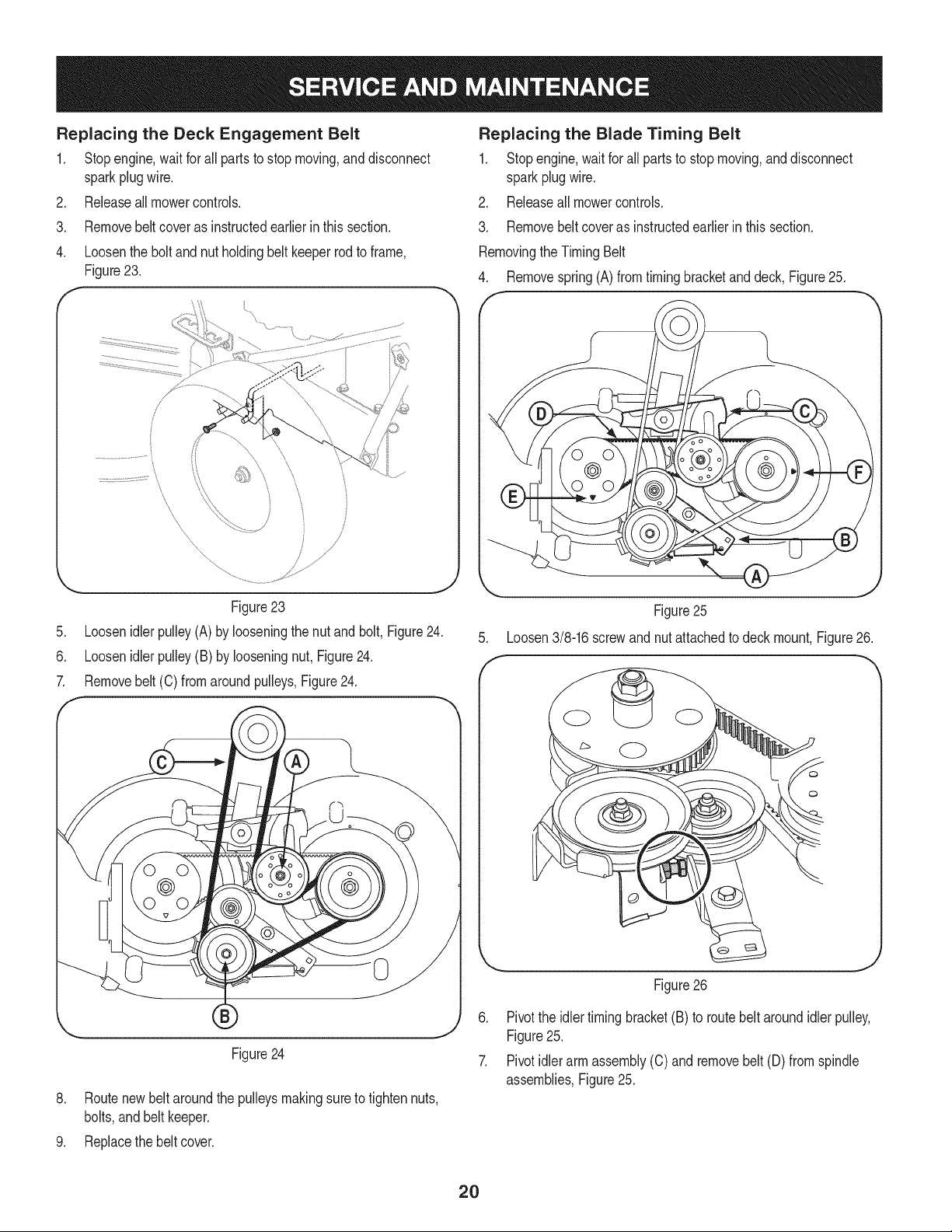
Removebelt coveras instructedearlier in this section.
Loosenbeltkeeper(A).The belt keeperis attachedto the
undersideof the mowerframe,Figure22.
Figure22
5. Loosenthe idler pulley(B) by looseningboltand nut, Figure22.
6. Removebelt (C) fromaround pulleys,Figure22.
7. Routenewbeltaroundthe pulleysmakingsureto tighten nuts,
bolts,and beltkeeper.
8. Replacethe beltcover.
19
Replacing the Deck Engagement Belt
1, Stopengine,wait for all partsto stop moving,and disconnect
sparkplugwire,
2. Releaseall mowercontrols,
3. Removebeltcoveras instructedearlierinthis section,
4. Loosenthe bolt and nut holdingbeltkeeperrod to frame,
Figure23.
f
.
6.
7.
\
i!
/
Figure23
Loosenidlerpulley(A) by looseningthe nutand bolt, Figure24.
Loosenidlerpulley(B) by looseningnut, Figure24.
Removebelt(C) fromaroundpulleys,Figure24.
0
Figure24
8. Routenew beltaroundthe pulleysmakingsureto tightennuts,
bolts,andbelt keeper.
Replacing the Blade Timing Belt
1. Stopengine,wait forall parts to stop moving,and disconnect
sparkplug wire.
2. Releaseall mowercontrols.
3. Removebelt coveras instructedearlierin thissection.
RemovingtheTimingBelt
4. Removespring(A) from timingbracketand deck,Figure25.
f
\
.
f
Figure25
Loosen3/8-16screwandnut attachedto deckmount,Figure26.
Figure26
6. Pivotthe idlertiming bracket(B) to routebelt aroundidler pulley,
Figure25.
7. Pivotidler armassembly(C) and removebelt (D) fromspindle
assemblies,Figure25.
9. Replacethe belt cover.
2O
InstallingtheTimingBelt
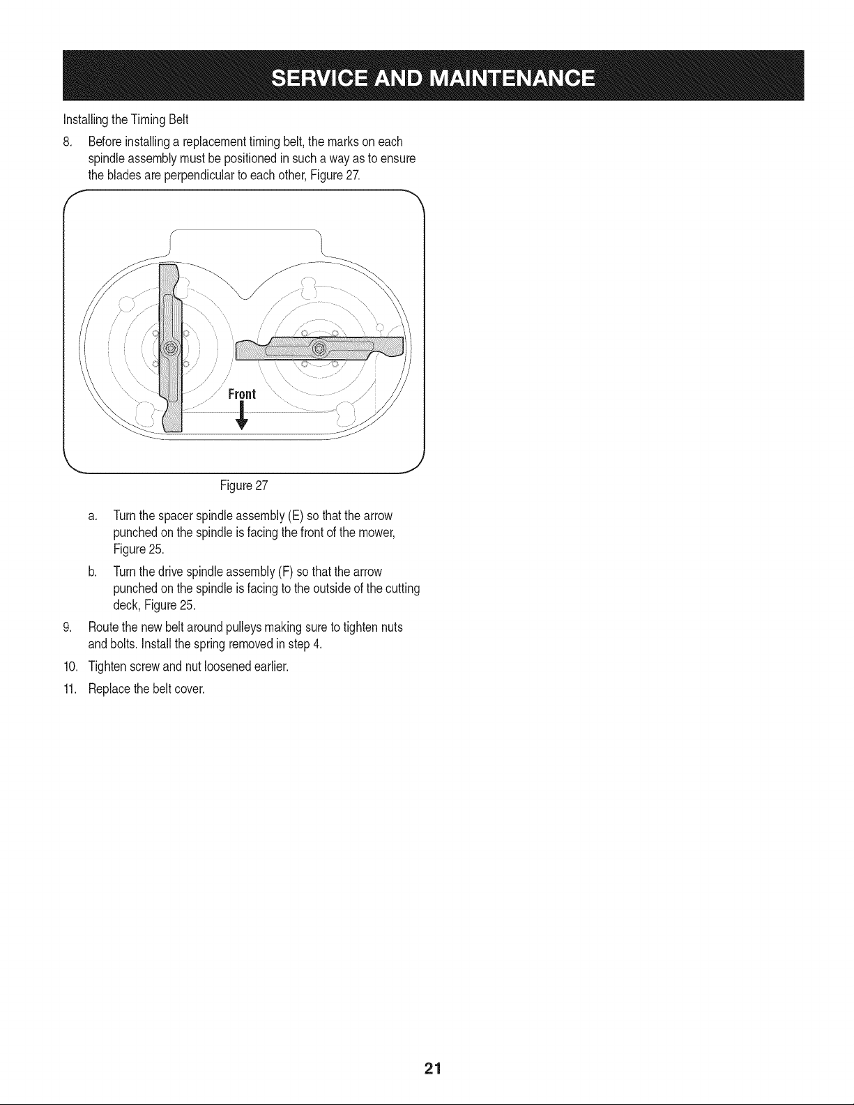
8. Beforeinstallinga replacementtimingbelt, the markson each
spindleassemblymustbe positionedin such a wayas to ensure
the bladesare perpendicularto eachother,Figure27.
f -,
7 J
/?///
.................Front
.
10.
11.
J
Figure27
a. Turnthe spacerspindleassembly(E) so thatthe arrow
punchedonthe spindleis facingthe frontof the mower,
Figure25.
b. Turnthe drivespindleassembly(F) so thatthe arrow
punchedonthe spindleis facingto the outsideof the cutting
deck,Figure25.
Routethe newbelt aroundpulleysmakingsureto tightennuts
andbolts.Installthe springremovedin step 4.
Tightenscrewand nutloosenedearlier.
Replacethebelt cover.
21
MAINTENANCE SCHEDULE
Beforeperforminganytypeof maintenance/service,disengageall
controlsandstoptheengine.Waituntilallmovingpartshavecometo
acompletestop.Disconnectsparkplugwireandgrounditagainstthe
enginetopreventunintendedstarting.Alwayswearsafetyglassesduring
operationor whileperforminganyadjustmentsor repairs.
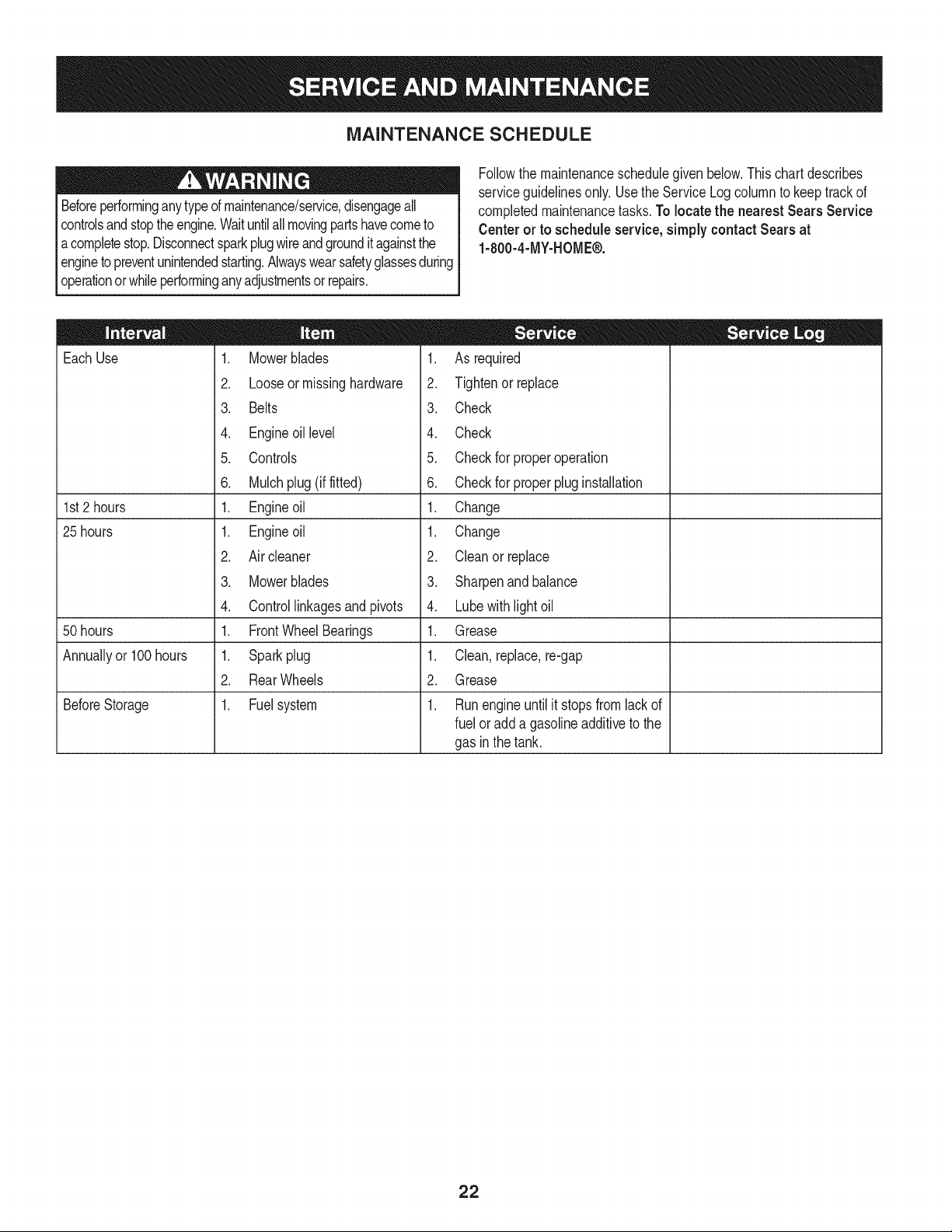
Followthe maintenanceschedulegivenbelow.Thischartdescribes
serviceguidelinesonly.Usethe ServiceLogcolumnto keeptrackof
completedmaintenancetasks.To locate the nearest Sears Service
Centeror to scheduleservice,simplycontactSears at
1-800-4-MY-HOME®.
EachUse
1st2 hours
25 hours
50 hours
Annuallyor 100hours
BeforeStorage
1. Mowerblades
2. Looseor missinghardware
3. Belts
4. Engineoil level
5. Controls
6. Mulchplug (if fitted)
1. Engineoil
1. Engineoil
2. Air cleaner
3. Mowerblades
4. Controllinkagesand pivots
1. FrontWheelBearings
1. Sparkplug
2. RearWheels
1. Fuelsystem
1. As required
2. Tightenor replace
3. Check
4. Check
5. Checkfor properoperation
6. Checkfor properplug installation
1. Change
1. Change
2. Cleanor replace
3. Sharpenand balance
4. Lubewith lightoil
1. Grease
1. Clean, replace,re-gap
2. Grease
1. Runengineuntilit stopsfrom lackof
fuel oradda gasolineadditiveto the
gas in thetank.
22
Neverstorelawnmowerwithfuel intankindoorsor in poorly
ventilatedareaswherefuel fumesmayreachan openflame,spark,
or pilot lightas ona furnace,waterheater,clothesdryer,or gas
appliance.
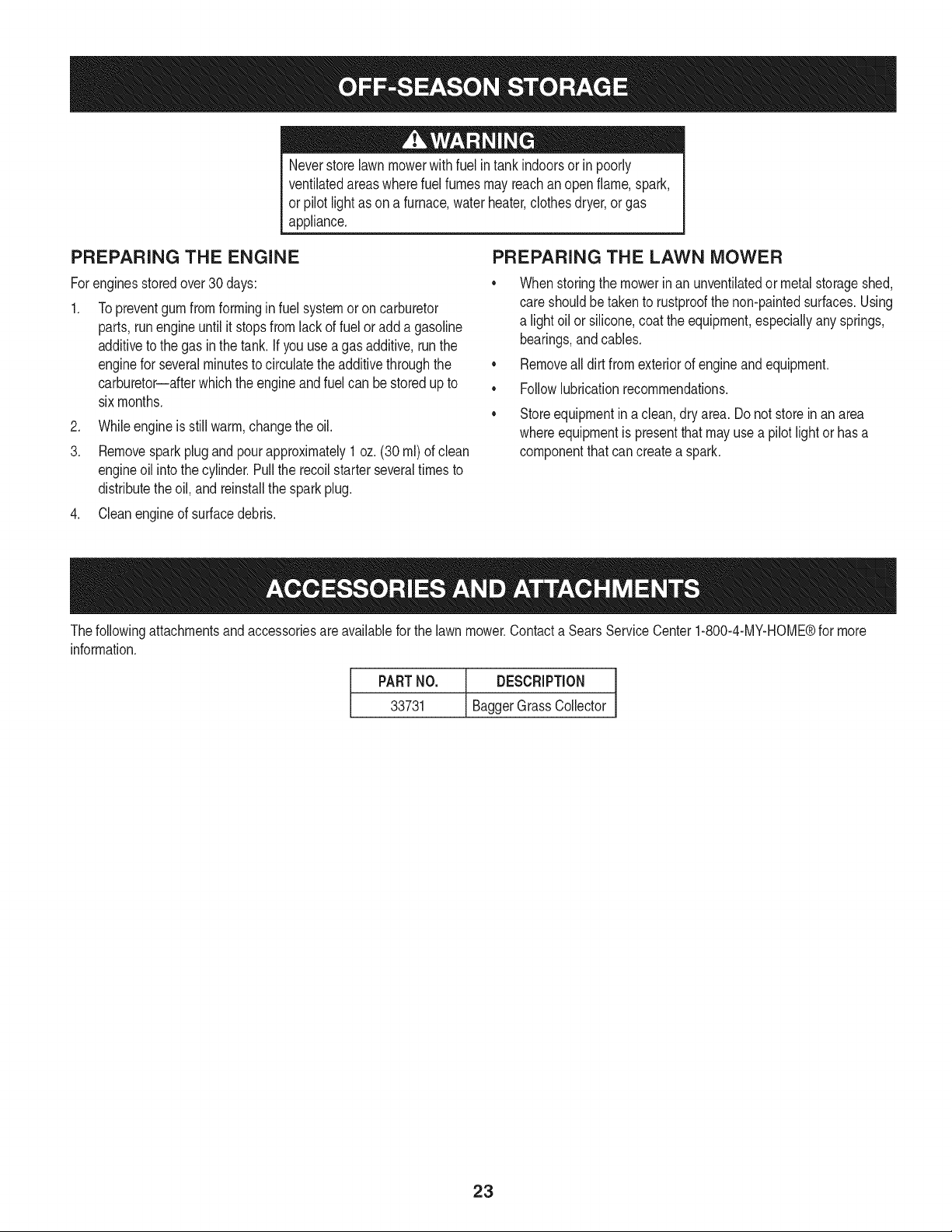
PREPARING THE ENGINE
Forenginesstoredover30days:
1. Topreventgum fromformingin fuel systemoron carburetor
parts,runengineuntil it stopsfromlackof fuel oradda gasoline
additivetothe gas in the tank.If youuse agas additive,runthe
enginefor severalminutesto circulatetheadditivethroughthe
carburetor--afterwhich the engineand fuelcan be storedup to
sixmonths.
2. Whileengineis still warm,changethe oil.
3. Removesparkplug and pour approximately1 oz. (30 ml)of clean
engineoil intothe cylinder.Pullthe recoilstarterseveraltimesto
distributetheoil, and reinstallthe spark plug.
4. Cleanengineof surfacedebris.
PREPARING THE LAWN MOWER
• Whenstoringthe mowerinan unventilatedor metalstorageshed,
careshouldbetaken to rustproofthe non-paintedsurfaces.Using
a lightoil orsilicone,coatthe equipment,especiallyany springs,
bearings,and cables.
• Removeall dirt from exteriorof engineandequipment.
• Followlubricationrecommendations.
Storeequipmentina clean, dryarea. Do notstore in an area
whereequipmentis presentthat mayuse a pilotlightor hasa
componentthatcan createa spark.
Thefollowingattachmentsandaccessoriesare availablefor the lawnmower.Contacta SearsService Center1-800-4-MY-HOME®for more
information.
PARTNO. DESCRIPTION
33731 BaggerGrass Collector
23
Beforeperforminganytyped maintenance/service,disengageall
controlsandstoptheengine.Waituntilallmovingpartshavecometo
a completestop.Disconnectsparkplugwireand groundit againstthe
engineto preventunintendedstarting.Alwayswearsafetyglassesduring
operationorwhileperforminganyadjustmentsorrepairs.
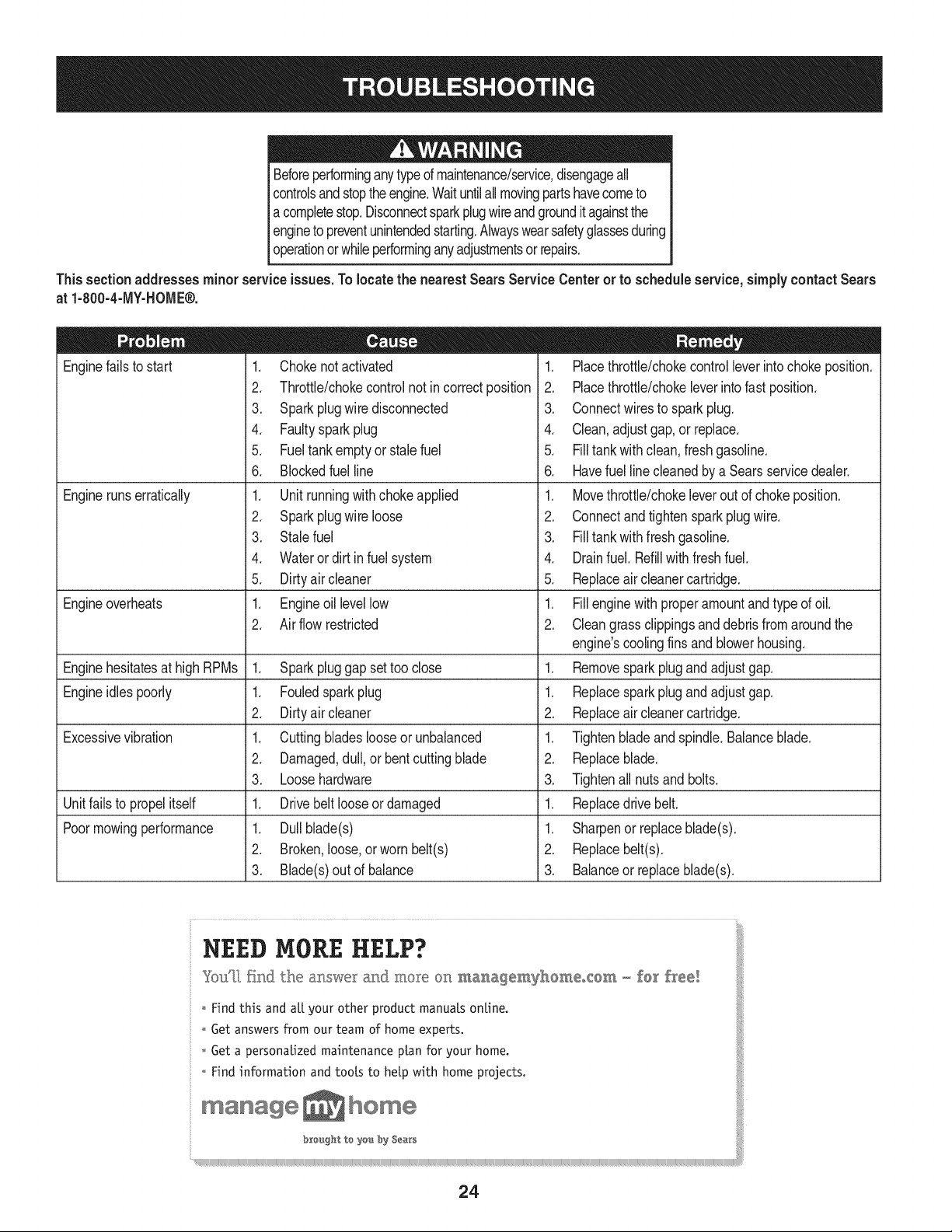
Thissectionaddresses minor serviceissues.Tolocate the nearestSearsServiceCenteror to scheduleservice,simplycontactSears
at 1-800-4-1VlY-HOIVlE®.
Enginefails to start
Enginerunserratically
1. Chokenotactivated
2. Throttle/chokecontrolnotin correctposition
3. Sparkplugwire disconnected
4. Faultyspark plug
5. Fueltank emptyor stale fuel
6. Blockedfuel line
1. Unit runningwithchokeapplied
2. Sparkplugwire loose
3. Stalefuel
4. Wateror dirt in fuel system
5. Dirtyair cleaner
1. Engineoil levellow
2. Air flow restricted
Engineoverheats
Enginehesitatesat highRPMs 1. Sparkpluggap settoo close 1.
Engineidles poorly 1. Fouledspark plug 1.
2. Dirtyair cleaner 2.
Excessivevibration 1. Cuttingbladeslooseor unbalanced 1.
2. Damaged,dull,or bentcuttingblade 2.
3. Loosehardware 3.
Unitfailsto propelitself 1. Drivebelt looseor damaged 1.
Poormowingperformance 1. Dullblade(s) 1.
2. Broken,loose,or wornbelt(s) 2.
3. Blade(s)out of balance 3.
1. Placethrottle/chokecontrolleverintochokeposition.
2. Placethrottle/chokeleverintofast position.
3. Connectwiresto sparkplug.
4. Clean,adjustgap,or replace.
5. Filltank with clean,fresh gasoline.
6. Havefuel line cleanedby a Searsservicedealer.
1. Movethrottle/chokeleverout of chokeposition.
2. Connectand tightenspark plugwire.
3. Filltank with fresh gasoline.
4. Drainfuel. Refillwith freshfuel.
5. Replaceair cleanercartridge.
1. Fillenginewith properamountandtype of oil.
2. Cleangrass clippingsand debrisfrom aroundthe
engine'scoolingfinsand blowerhousing.
Removesparkplugand adjustgap.
Replacesparkplugand adjustgap.
Replaceair cleanercartridge.
Tightenbladeand spindle.Balanceblade.
Replaceblade.
Tightenall nuts and bolts.
Replacedrivebelt.
Sharpenor replaceblade(s).
Replacebelt(s).
Balanceor replaceblade(s).
NEED MORE HELP?
You"[[ £nd the ar_,swer and more on ma_,agemyhOmeo{Om - fo[ free!
_ o Findthis and a[l your other product manuals online.
:: o Get answers from our team of home experts.
o Get a personaUzedmaintenance plan for your home.
o Find information and tools to help with home projects.
24
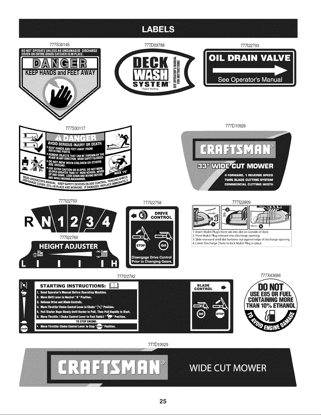
777S30145 777D09788 777122793
777S30117
777D10928
777122759
777122760
777122758 777122809
1. Insert Mulch Plug's front tab into slot on outside of deck.
2. Pivot Mulch Plug inboard into discharge opening.
3. Slide rearward until slot bottoms out against edge of discharge opening.
. Lower Discharge Chute to lock Mulch Plug in place.
777122782
777X43688
777D10929
25
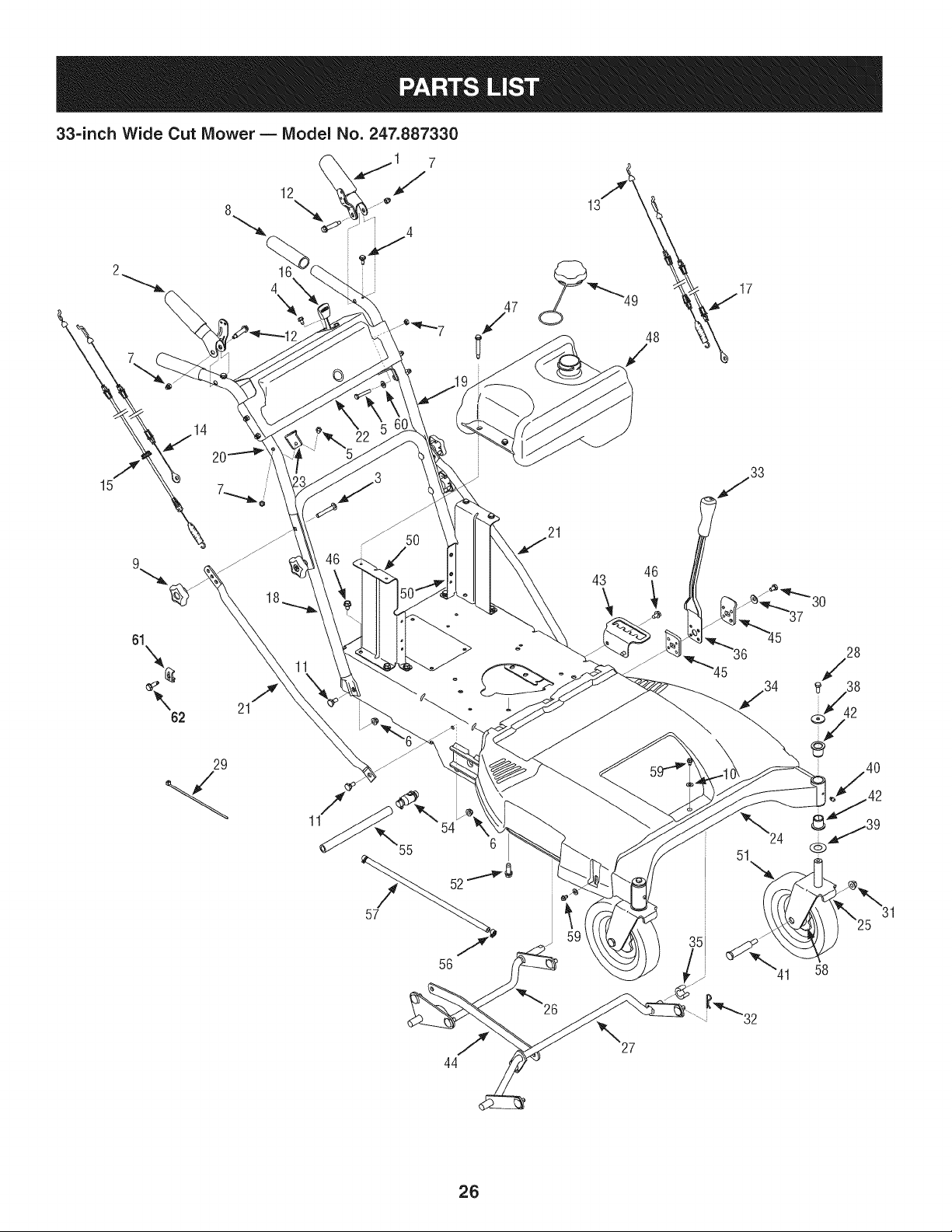
33-inch Wide Cut Mower B Model No. 247.887330
8
4
61
\
62
21
/
21
46
43
57
54
56
44
26
51
32
41
25
58
26

33=inch Wide Cut Mower B Model No. 247.887330
D = " O
687-02427 LeverAssembly:LH
2 687-02426 LeverAssembly:RH
3 710-0572 Screw,Carriage:5/16-18x 2.25"
4 710-0599 Screw,TT:1/4-20x 0.500"
5 710-0606 Screw,HHCap:1/4-20x 1.50"
6 712-04063 Nut, FlangeLock:5A6-18
7 912-0442 Nut, LockCap:1/4-20
8 720-0274 Grip: 1.0"IDx 5.0" Lg
9 720-04072A Star Knob5A6-18
10 936-0463 Washer,Flat:.25x .63x .0515
11 938-0140 Screw,Shoulder:.435"x.178-5/16
12 938-1226 Screw,Shoulder:.375"x 1.355"x 1/4-20
13 946-04609 Cable,ClutchWheel
14 946-04606 Cable,Brake,Transmission:RH
15 946-04610 Cable,ClutchDeck
16 946-04604 Cable,Throttle/Choke:38" x 1.1"Ext
17 946-04608 Cable,Brake,Transmission:LH
18 749-04330-0637LowerHandle
19 749-04331-0637 UpperHandle:LH
20 749-04332-0637 UpperHandle:RH
21 749-04333-0637 BraceTube
22 787-01540-4044 HandlePanel
23 787-01490A-0637CableMountBracket:RH
787-01491A-0637CableMountBracket:LH
24 687-02255B-4044FrameAssembly
25 687-02263-4044 CasterWheelBracketAssembly
26 687-02419-0637 DeckLift Assembly:RR
27 687-02265-0637 DeckLift Assembly:Front
28 710-0627 Screw,HHCap:5/16-24x .750"
29 725-0157 CableTie,3/16x .05x 7.4
30 710-04312 Screw,HH Cap: 5/16-18x .50"
712-04065
132 1914-0145
133 720-0311
134 931-05684
135 731-05791
136 732-04418A
137 736-0242
138 736-0343
]39 936-0351
140 1937-3000
141 738-04216A
142 741-0660A
143 i787-01496-4044
144 i787-01510-0637
145 787-01521-0637
146 710-0604A
147 938-1225
148 951-10480
149 951-10514
150 787-01507-4044
151 734-04243
152 710-1315
154 951-10517A
155 751-3141-14
j56 726-0205
157 751-10349-28
158 941-0706
159 710-0896
j60 736-0270
j61 751B221535
j62 710-1237
Nut,FlangeLock:%-16
ClickPin: .092"x 1.64"
HandleGrip1/2"
BeltCover33"Wide CutMower
iSnapSpacer:.63" IDx .75" LG
iDeckHeightLever
iWasher,Bell: .340"x .872"x .060"
]Washer,Flat:.330" x 1.25"x .120"
iWasher,Flat:.760"IDx 1.50"OD
LubeFitting:3A6:LNC#70
]Bolt,Shoulder:.625"x 2.515"x %-16
]FlangeBearing:.760"x .941"x 1.0"
iHeightAdjustmentBracket
LinkPivotBracket
LeverPivotBracket
jScrew,TT: 5/16-18x .625"
iScrew,Shoulder:.3175"x .188"x ¼-20
]FuelTank,2 Gal.
iFuelCap
FuelTankMountingBracket
iWheel,8"x 1.75"
iScrew,TT: %-16x 1.25"
lOil Drain
lOil DrainHose
HoseClamp
FuelHose
lFlangeBearing,.635"
lScrew,¼-14x .625
lWasher,Bell:.265"x .75"x .062"
lCasingClamp
]Screw,10-32X .625
27
33=inchWide Cut Mower B Model No. 247.887330
13
f
67
19
17
28
29
\
72
6O
59
26
14
61
63
39
i5
64
A _65
@
28

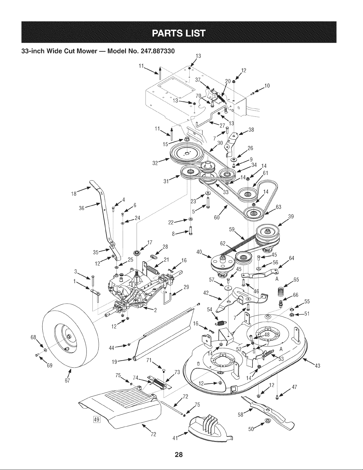
33=inch Wide Cut Mower B Model No. 247.887330
17840-0637 TransaxleBracketMount 918-04439B SpacerSpindleAssembly
2 918-04639 Transmission4-Speed i41 i631-04252 Mulch Plug
3 710-0176 Screw,HHCap:5/16-18x 2.75" i42 i987-02420 IdlerArm Assembly
4 710-0376 Screw,HHCap:5/16-18x 1.00" i43 687-02476-4044 DeckAssembly33-inch
5 710-04377 Screw,HHCap: 7/16-20x 2.75" i44 710-04187 Screw,HL: 1A-15x .50"
6 710-0513 Screw,HHCap:1/4-28x .625" i45 710-0514 Screw,HHCap:%-16x 1.00"
7 710-0520 Screw,HHCap:%-16x 1.50" i46 i710-0560 Screw,Carriage:%-16x 1.75"
8 710-0347 Screw,HHCap:%-16x 1.75" i47 710-04484 Screw,5/16-18x .750
9 710-3008 Screw,HHCap:%6-18x .75" i48 710-3184A Screw,HH Cap: %-16x 2.00"
10 710-3015 Screw,HHCap:_A-20x .75" i49 931-04244 ChuteDeflectorAssy(includesref.72-76)
11 911-1000 BeltKeeper i50 712-0417A Nut, Flange:%-18
12 712-04063 Nut,FlangeLock:5/16-18 i51 912-0641 Nut, Hex
13 712-04064 Nut,FlangeLock:_A-20 i52 912-3017 Nut, Hex%-16
14 712-04065 Nut,FlangeLock:%-16 i53 732-04406 ExtensionSpring:TimingBeltTension
15 712-0700 Nut,Flange:9A6-18 i54 732-04452 ExtensionSpring:DeckBrake
16 914-0145 HairpinClip:092"x 1.64"Long i55 736-0225 Washer,Lock
17 718-04407 PulleyHub i56 938-0347 Spacer,Shoulder:.625"x .169"
18 720-0142 Grip i57 738-04162A Spacer,Shoulder:.884"x .190"
19 731-05766 TrailingShield 58 i942-04154A Blade:17.9"
20 732-04409 ExtensionSpring i59 754-04136 Belt,Timing
21 732-04443A ExtensionSpring i60 i954-04139 Belt,V Type,DeckEngagementBelt
22 736-0105 Washer,Spring:.401"x .870"x .063" i61 i756-04129B IdlerPulley4.25"
23 736-0322 Washer,Fiat:450"x 1.250"x .164" i62 756-04280 IdlerPulley3.50"
24 736-0270 Washer,Bell i63 756-0616 IdlerPulleyV-Type5.0"
25 736-04256 Washer,Fiat:.39" x .87" x .06" i64 787-01440-0637 IdlerTimingBracket
26 738-04166 Spacer,Shoulder:.50"x .1475" i65 921-04041 WaterNozzleAdapter
27 747-04635A BeltKeeperRod i66 737-04003D WaterNozzle
28 747-04673 LoopLinkCoupling i67 634-04285-0911 Wheel16x 4x 8
29 747-04678A TransMountRod i68 i736-0242 Washer,Bell: .340"x .872"x .060"
30 954-04145A Belt,V Type,DriveBelt i69 710-0627 Screw,HHCap:%6-24x .75"
31 756-04129B IdlerPulley:4.25" Dia. i70 710-1315 Screw,TT:%-16x 1.25"
32 756-04258 FlatSheave7.75" i71 710-0451 Bolt,Carriage:%6-18x .75"
33 756-04260 EnginePulley3.20" x 4.35" Dia. i72 711-04027 DeflectorPin
34 756-04280 IdlerPulley3.50" Dia. i73 787-01017A-0637DeflectorHingeBracket
35 787-01469B-4044Shift Rod,Lower i74 732-04012 DeflectorTorsionSpring
36 787-01470A-0637Shift Rod,Upper i75 726-04009 PushCap
37 787-01473-0637 BeltKeeper i76 -- ChuteDeflector,33" SD Deck
38 787-01523A WheelDriveidlerBracket 977S30145 LabelChuteDeflector(notshown)
39 918-04438B Drive SpindleAssembly
29
33=inch Wide Cut Mower m Model No. 247.887330
27
21 29
20,,_/22 I
I
71B
o/
\1
83
18 49
/
157
47
/
31A
13
/
15
29B
13
31A
3O
56
69
50
30
57
58
48
51
59
52
64
64
65
34 /
63 87
63
29
/ 35
3/
37
41
40
157
d
MODELand SERIAL
NUMBERSHERE
30

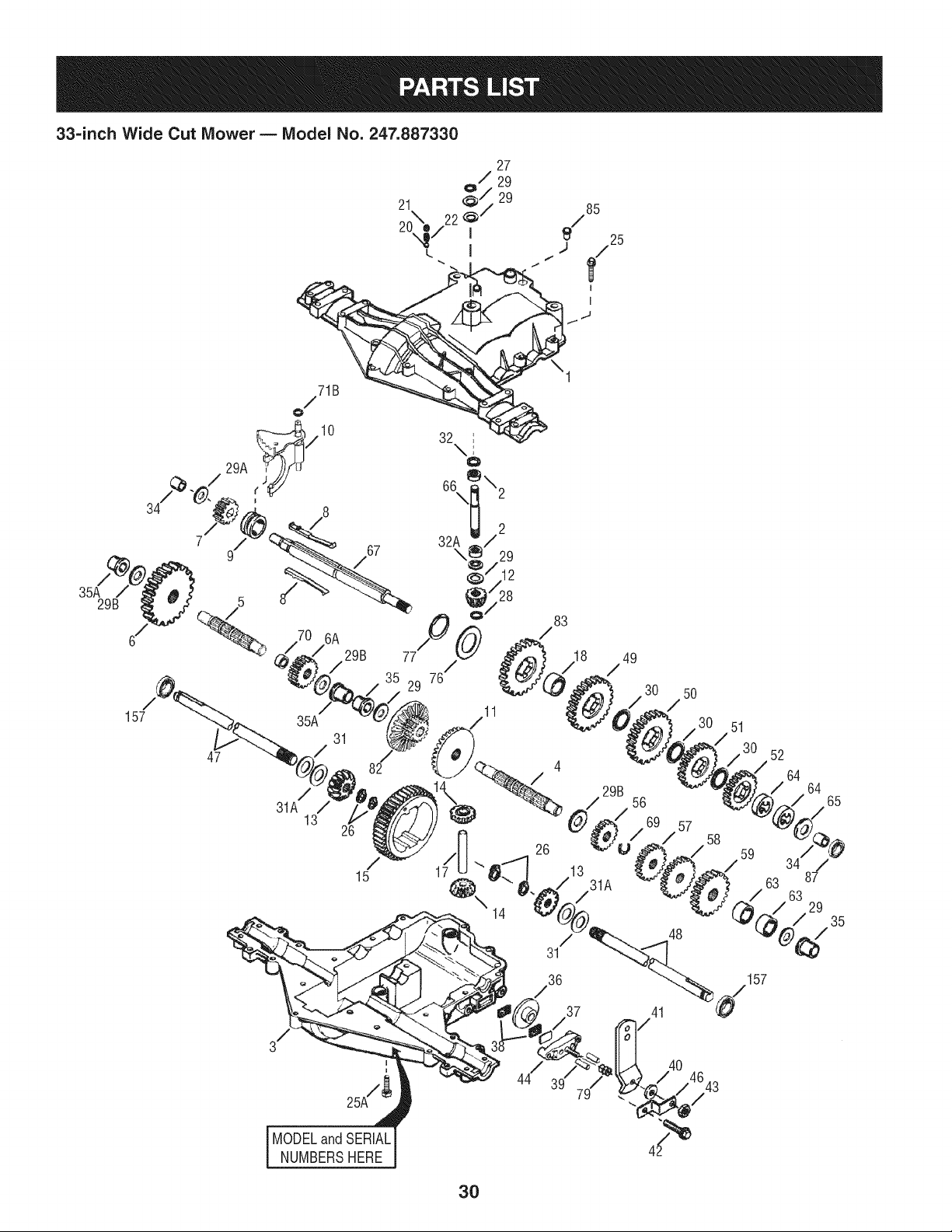
33-inch Wide Cut Mower B Model No. 247.887330
D = O O
TC-772147 TransaxleCover
2 TC-780086A NeedleBearing(1/,,long)
3 TC-770128A TransaxleCase
4 TC-776395 Countershaft
5 TC-776409 OutputShaft
6 T0-778364 SpurGear(38T-PM/SER)
6A T0-778369 Spur Gear(15T-PM/SER)
7 T0-778330 SpurGear(11T-PM/SER)
8 TC-792180A ShiftKeySet (Qty.2)
9 TC-784352 ShiftCollar
10 TC-784378 Shift Rod& ForkAssembly
11 TC-778334 BevelGear (30T-PM)
12 TC-778309 Input BevelPinion(13T-PM)
13 TC-778368 BevelGear 13T(Incl. ref.13& 14)
14 TC-778368 BevelGear 13T(Incl. ref.13& 14)
15 T0-778370 RingGear (43T)
17 TC-786188 DrivePin
18 TC-786102 Spacer(1.130"x .695")
20 TC-792077A Ball(StainlessSteel5/16" dia.)
21 TC-792211 Screw,3/8-16x 3/8"
22 TC-792079 Spring
25 TC-792073A Screw,1/4-20x 1-1/4"
25A TC-792177 Screw,1/4-20x 1-3/8"
26 TC-792125 RetainingRing-packageof 2
27 TC-792035 RetainingRing
28 TC-788040 RetainingRing
29 TC-780072 Washer.627"ID .031"
29A TC-780160 ThrustWasher(.563"IDx .031")
29B TC-780051 ThrustWasher(.762"IDX .031")
30 T0-780108 ShiftWasher(Cupped)
31 TC-780001 Washer.750"ID .56"
31A TC-780195 Washer.750"ID .062
32 TC-788083 OilSeal5/8"
32A TC-792001 O Ring(.823"OD)
34 TC-780194 Bushing(.563")
35 TC-780193 FlangedBushing(.625"ID)
35A TC-780197 FlangedBushing(.751"ID)
TC-790075 BrakeDisk
37 TC-790007 BrakePadPlate
38 TC-799021A BrakePad(pkg.of 2)
39 TC-786026 DowelPin.3125"x .750"
40 736-3078 Washer.312"ID.059"
41 TC-790104 BrakeLever
42 TC-792177 Screw1/4-20x 1-3/8"
43 912-0237 LockNut5/16-24
44 TC-790025 BrakePadHolder
46 TC-786086 Bracket
47 T0-775146 Axle (10.719"long) (Incl.26)
48 T0-775147 Axle (15.312"long)(Incl.26)
49 TC-778338 SpurGear(27T-PM/IC)
50 TC-778342 SpurGear(22T-PM/IC)
51 TC-778313 SpurGear(19T-PM/IC)
52 TC-778350 SpurGear(16T-PM/IC)
56 TC-778337 SpurGear(13T-PM/SER)
57 TC-778341 SpurGear(18T-PM/SER)
58 TC-778351 SpurGear(21T-PM/SER)
59 TC-778349 SpurGear(24T-PM/SER)
63 TC-786071 CountershaftSpacer1-1/8"x 3/8"
64 TC-786072 BrakeShaftSpacer1-3/8"x 3/8"
65 TC-780189 Washer.563"ID .062
66 TC-776472 inputShaft
67 TC-776396 BrakeShaft
69 TC-792170 RetainingRing(.75"x .042")
70 TC-786187 Spacer(.890")
71B TC-788092 O-Ring
76 TC-780090 FiatWasher(1.128"IDx .058")
77 TC-788078A RetainingRing(1.125"x .050")
79 TC-792144 Spring
82 TC-778333 Bevel(30T)& Spur Gear
83 TC-778338 SpurGear(27T-PM/IC)
85 TC-792154 Oil FillPlug
87 TC-788089A Oil Seal9/16" ID
157 TC-788088A Oil Seal3/4" ID
31
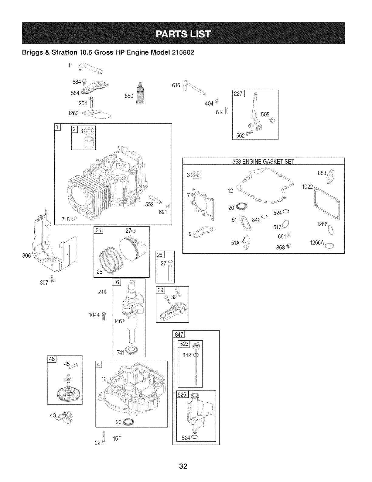
Briggs & Stratton 10.5 Gross HP Engine IViodel 215802
11
684_ f&%\._
584_/_-_
1264 _
1263 _-../ -,
....... /
85O
|
307_j
24_?
1044
741_
200
1_ 15÷
22
616
32
2271
4O4_
614i_
562
358 ENGINEGASKETSET
12
200
51
51A
842 <d>
524°
1022
5240
883
32
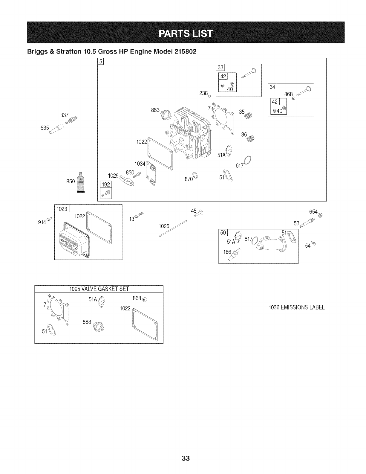
Briggs & Stratton 10.5 Gross HP Engine Model 215802
33_
635J_Y
85O
238._
,y
36_
1022
1034
1029 87_
9146_'
1022
4_
51
654_
54%
1095VALVEGASKETSET
51A
1022
868_,
1036EMISSIONSLABEL
33
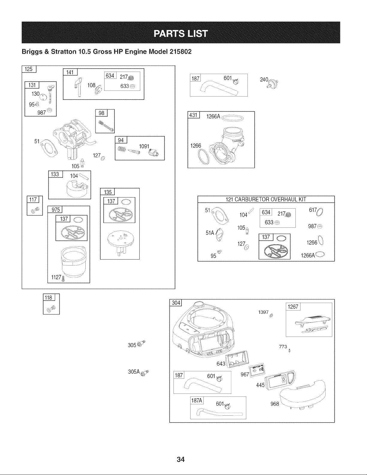
Briggs & Stratton 10.5 Gross HP Engine Model 215802
13>
956
987_
1411
51
634_ 217m_}a
633 _-*')
W 1091
1276` I _' _-
| F%,
601
4311 1266AdJ...........::::::%
51
51A
95 _y
121CARBURETOROVERHAULKiT
6341 217_ 1
633,_
_o
987,_9
f\
1266_C=
1266A_I )
305d 9
187A 601
1397 @
773
®
34
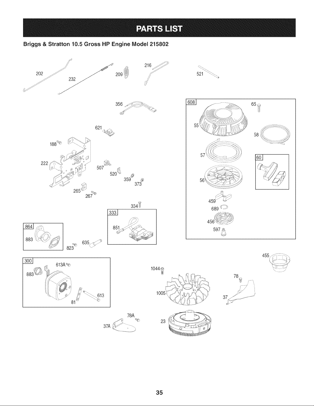
Briggs & Stratton 10.5 Gross HP Engine IViodel 215802
S_ _
202 _z j_
_ 232_
216_._ _.
,t 521 _-%
356 _/_ _5"._
621
82_
81
520_
359_
373
334_
I 1561/.!/ ,>_ >_.,
I _;_ _'i _W_j
/
1044_
78A
37A
23
65 _
58
57
689 _ ':¢_
455,/
,,,,1!SI!y>*-
, '_t__',_si,_i_.-_
78_i_ ...........
r /"
35

Briggs & Stratton 10.5 Gross HP Engine Model 215802
BS-697377 CylinderAssembly BS-690227 Stud (Carburetor)
2 BS-399265 Kit-Bushing/Seal(MagnetoSide) 54 BS-691148 Screw(intakeManifold)
3 BS-391086s • Seal-Oil(MagnetoSide) 55 BS-695130 Housing-RewindStarter
4 BS-697106 Sump-Engine 56 BS-695129 Pulley-Starter
5 BS-796183 Head-Cylinder 57 BS-695131 Spring-RewindStarter
7 BS-273280s o+ Gasket-CylinderHead 58 BS-695132 Rope-Starter
9 BS-697109 • Gasket-Breather 60 BS-494212 Grip-StarterRope
10 BS-697157 Screw(BreatherAssembly) 65 BS-690759 Screw(RewindStarter)
11 BS-794683 Tube-Breather 78 BS-691003 Screw(FlywheelGuard)(10/24x.43)
12 BS-697110 ° Gasket-Crankcase 78A BS-690364 Screw(FlywheelGuard)(5/16-18x.37)
13 BS-690360 Screw(CylinderHead) 81 BS-691178 Lock-MufflerScrew
15 BS-690946 Plug-OilDrain 94 BS-793610 Kit-IdleMixture
16 BS-796146 Crankshaft 95 BS-690718 O Screw(ThrottleValve)
20 BS-795387 • SeaI-Oil(PTOSide) 98 BS-695408 Kit-ldleSpeed
22 BS-692125 Screw(CrankcaseCover/Sump) 104 BS-694918 O Pin-FloatHinge
23 BS-695774 Flywheel 105 BS-696136 O Valve-FloatNeedle
24 BS-222698s Key-Flywheel 108 BS-698773 Valve-Choke
25 BS-797009 PistonAssembly(Standard) 117 BS-796079 Jet-Main(Standard)
BS-797010 PistonAssembly(.020"Oversize) 118 BS-796332 Jet-Main(HighAltitude)
26 BS-797011 RingSet (Standard) 121 BS-796184 Kit-CarburetorOverhaul
BS-797012 RingSet (.020"Oversize) 125 BS-794653 Carburetor
27 BS-698469 Lock-PistonPin 127 BS-690727 O Plug-Welch
28 BS-797013 Pin-Piston 130 BS-698774 Valve-Throttle
29 BS-791633 Rod-Connecting 131 BS-698776 Kit-ThrottleShaft
32 BS-791118 Screw(ConnectingRod) 133 BS-694914 Float-Carburetor
33 BS-791934 Valve-Exhaust 135 BS-698780 Tube-FuelTransfer
34 BS-791935 Valve-intake 137 BS-698781 O Gasket-FloatBowl
35 BS-691279 Spring-Valve(intake) 141 BS-698778 Kit-ChokeShaft
36 BS-691279 Spring-Valve(Exhaust) 146 BS-691639 Key-Timing
37 BS-697352 Guard-Flywheel 187 BS-791805 Line-Fuel
37A BS-697626 Guard-Flywheel 187A BS-791744 Line-Fuel
40 BS-690964 Retainer-Valve 188 BS-691693 Screw(ControlBracket)
42 BS-499586 Keeper-Valve 192 BS-691986 Adjuster-RockerArm
43 BS-691968 Slinger-Governor/Oil 202 BS-691841 Link-MechanicalGovernor
45 BS-690564 Tappet-Valve 209 BS-792813 Spring-Governor(Brown)
46 BS-793880 Camshaft 216 BS-691840 Link-Governor
48 BS-697740 ShortBlock 217 BS-695409 O Spring-ChokeReturn
50 BS-796188 Manifold-Intake 222 BS-694042 Bracket-Control
51 BS-692137 o+O Gasket-intake 227 BS-691374 Lever-GovernorControl
51A BS-794312 o+O Gasket-intake 232 BS-691842 Spring-GovernorLink
36

Briggs & Stratton 10.5 Gross HP Engine Model 215802
BS-691843 Cap-Valve BS-692138 SeaI-ORing(IntakeManifold)(Red)
240 BS-394358s Filter-Fuel 621 BS-692310 Switch-Stop
265 BS-691024 Clamp-Casing 633 BS-699813 O Seal-Choke/ThrottleShaft
267 BS-794904 Screw(CasingClamp) 634 BS-698779 O Spring/SealAssembly
300 BS-796000 Muffler 635 BS-691909 Boot-SparkPlug
304 BS-796414 BlowerHousing 643 BS-697155 Retainer-AirFilter
305 BS-697102 Screw(BlowerHousing)(Long) 654 BS-690958 Nut(Carburetor)
305A BS-793376 Screw(BlowerHousing)(Short) 689 BS-691855 Spring-Friction
306 BS-697359 Shield-Cylinder 691 BS-692407 • Seal-GovernorShaft
307 BS-691003 Screw(CylinderShield) 718 BS-690959 Pin-Locating
333 BS-795315 Armature-Magneto 741 BS-697128 Gear-Timing
334 BS-691061 Screw(MagnetoArmature) 773 BS-796448 Retainer
337 BS-491055s Plug-Spark 823 BS-698941 Screw(MufflerAdapter)
356 BS-398808 Wire-Stop 830 BS-691095 Stud-RockerArm
358 BS-796181 GasketSet-Engine 842 BS-691031 • SeaI-ORing(DipstickTube)
359 BS-691077 Washer(GroundTerminal) 847 BS-790442 Dipstick/TubeAssembly
373 BS-691612 Nut(GroundTerminal) 850 BS-100106 Sealant-Liquid
404 BS-691691 Washer(GovernorCrank) 851 BS-692424 Terminal-SparkPlug
431 BS-697122 Elbow-Intake 864 BS-796002 Adapter-Muffler
445 BS-698413 Filter-AirCleanerCartridge 868 BS-690968 o+ Seal-Valve
455 BS-695113 Cup-Flywheel 883 BS-692236 o+ Gasket-Exhaust
456 BS-695128 Plate-PawlFriction 914 BS-691108 Screw(RockerCover)
459 BS-281505s PawI-Ratchet 967 BS-697292 Filter-PreCleaner
505 BS-691251 Nut(GovernorControlLever) 968 BS-697420 Cover-AirCleaner
507 BS-691972 Insulator 975 BS-698783 Bowl-Float
520 BS-691084 Terminal-Ground 987 BS-698777 O Seal-ThrottleShaft
521 BS-690581 Shield-Cable 1005 BS-796082 Fan-Flywheel
523 BS-699908 Dipstick 1022 BS-272475s o+ Gasket-RockerCover
524 BS-691032 ° Seal-DipstickTube 1023 BS-797421 Cover-Rocker
525 BS-697184 Tube-Dipstick 1026 BS-794573 Rod-Push(Exhaust)
552 BS-697144 Bushing-GovernorCrank BS-697394 Rod-Push(Intake)
562 BS-691119 Bolt(GovernorControlLever) 1029 BS-691751 Arm-Rocker
584 BS-794682 Cover-BreatherPassage 1034 BS-690822 Guide-PushRod
597 BS-691696 Screw(PawlFrictionPlate) 1036 Label-Emissions(Availablefroma
601 BS-791850 Hose-Clamp(Green) Briggs& StrattonAuthorizedDealer)
608 BS-695058 Starter-Rewind 1044 BS-698139 Screw(Flywheel)
613 BS-691416 Screw(Muffler)(Long) 1091 BS-691333 Cap-Limiter
613A BS-691678 Screw(Muffler)(Short) 1095 BS-796189 GasketSet-Valve
614 BS-691620 Pin-Cotter(GovernorCrank) 1127 BS-695407 Screw(FloatBowl)
616 BS-692012 Crank-Governor 1263 BS-697124 Reed-Breather
37

Briggs & Stratton 10.5 Gross HP Engine Model 215802
BS-697104
1266 BS-691917 •O
1266A BS-697123 •O
1267 BS-697419
1397 BS-796449
1329 BS_15802-0015-G1
o
Screw(BreatherReed)
Seal-ORing(intakeElbow)(Red)
Seal-ORing(intakeElbow)(Large)
Latch-BlowerHousing
Washer(BlowerHousing)
ReplacementEngine
includedin EngineGasketSet, KeyNumber358
+ includedinValveGasketSet, KeyNumber1095
0 includedinCarburetorOverhaulKit, KeyNumber121
38

Congratulationson makinga smartpurchase.YournewCraftsman@
productis designedandmanufacturedfor yearsof dependableopera-
tion.But likeall products,it may requirerepairfrom time to time.That's
whenhavinga RepairProtectionAgreementcansave youmoneyand
aggravation.
Here'swhat the RepairProtectionAgreement*includes:
* Expert service byour 10,000professionalrepairspecialists
o Unlimitedserviceand no chargefor partsand laboron all
coveredrepairs
o Product replacementupto $1500if yourcoveredproductcan't be
fixed
• Discountof 10%from regularprice of serviceand relatedinstalled
partsnotcoveredby theagreement;also, 10%off regularpriceof
preventivemaintenancecheck
• Fast help by phone- we call it RapidResolution- phone support
froma Searsrepresentative.Thinkof usas a "talkingowner's
manual."
Onceyou purchasethe Agreement,a simplephonecall is all that it
takesfor youto scheduleservice.Youcan call anytimedayor night,or
schedulea serviceappointmentonline.
The RepairProtectionAgreementis a risk-freepurchase.If youcancel
for any reasonduringthe productwarrantyperiod,wewill provideafull
refund.Or,a proratedrefundanytimeafter the productwarrantyperiod
expires.Purchaseyour RepairProtectionAgreementtoday!
Somelimitationsand exclusionsapply. For pricesand additional
informationin the U.S.A. call 1-800-827-6655.
*Coverage inCanadavaries on some items.Forfull details call
Sears Canadaat 1-800-361-6665.
Sears Installation Service
ForSearsprofessionalinstallationof homeappliances,garagedoor
openers,waterheaters,andothermajorhomeitems,in the U.S.A.or
Canadacall 1-800-4-MY-HOME®.
39
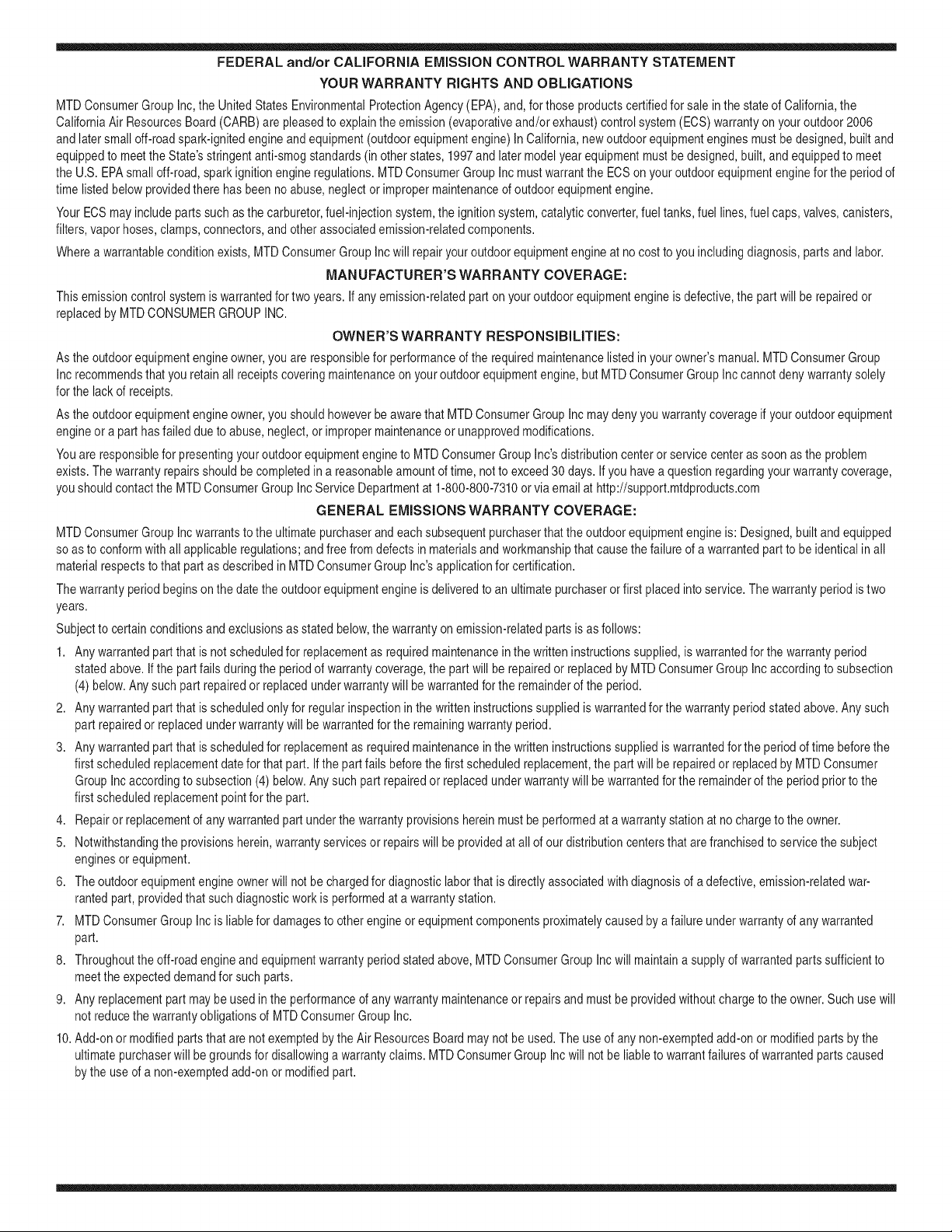
FEDERAL and/or CALIFORNIA EMISSION CONTROL WARRANTY STATEMENT
YOUR WARRANTY RIGHTS AND OBLIGATIONS
MTDConsumerGroupInc,the UnitedStatesEnvironmentalProtectionAgency (EPA),and, forthose productscertifiedfor sale in the stateof California,the
CaliforniaAir ResourcesBoard(CARB)are pleasedto explainthe emission(evaporativeand/or exhaust)controlsystem(ECS) warrantyon youroutdoor 2006
andlater smalloff-roadspark-ignitedengineandequipment(outdoorequipmentengine)In California,new outdoorequipmentengines mustbe designed,built and
equippedto meetthe State'sstringentanti-smogstandards(in otherstates, 1997andlater modelyear equipmentmustbe designed,built, and equippedto meet
theU.S. EPAsmalloff-road, sparkignitionengineregulations.MTDConsumerGroupInc mustwarrantthe ECSon your outdoorequipmentenginefor the periodof
timelisted belowprovidedtherehas been no abuse, neglector impropermaintenanceof outdoor equipmentengine.
Your ECSmay includeparts such as the carburetor,fuel-injectionsystem,the ignitionsystem,catalyticconverter,fuel tanks,fuel lines,fuelcaps, valves,canisters,
filters,vapor hoses,clamps,connectors,andotherassociatedemission-relatedcomponents.
Wherea warrantableconditionexists, MTDConsumerGroupIncwill repairyouroutdoorequipmentengine at no cost to you includingdiagnosis,parts and labor.
MAN UFACTURER'S WARRANTY COVERAGE:
Thisemissioncontrolsystemis warrantedfor two years. If any emission-relatedpart on your outdoorequipmentengine is defective,the part will berepairedor
replacedby MTDCONSUMERGROUPINC.
OWNER'S WARRANTY RESPONSIBILITIES:
Asthe outdoorequipmentengineowner,you are responsiblefor performanceof the requiredmaintenancelisted inyour owner'smanual.MTDConsumerGroup
Inc recommendsthat you retain all receiptscoveringmaintenanceon youroutdoorequipmentengine,butMTDConsumerGroup Inc cannotdeny warrantysolely
forthe lackof receipts.
Asthe outdoorequipmentengineowner,you shouldhoweverbe awarethat MTDConsumerGroupInc maydenyyou warrantycoverageif your outdoorequipment
engineor a part has faileddue to abuse,neglect,or impropermaintenanceor unapprovedmodifications.
Youare responsiblefor presentingyouroutdoor equipmentengineto MTDConsumerGroupInc'sdistributioncenterorservicecenteras soon asthe problem
exists.The warrantyrepairsshouldbe completedin a reasonableamountof time, notto exceed30 days.If you havea questionregardingyour warrantycoverage,
you shouldcontactthe MTDConsumerGroupIncService Departmentat 1-800-800-7310or via emailat http://support.mtdproducts.com
GENERAL EMISSIONS WARRANTY COVERAGE:
MTDConsumerGroupIncwarrantsto the ultimatepurchaserand eachsubsequentpurchaserthat theoutdoor equipmentengine is: Designed,built and equipped
so asto conformwithall applicableregulations;and freefromdefects in materialsand workmanshipthatcausethe failureof a warrantedpart to be identicalin all
materialrespectsto that part as describedin MTDConsumerGroup Inc'sapplicationfor certification.
The warrantyperiodbeginson the date theoutdoorequipmentengineis deliveredto an ultimate purchaserorfirst placedinto service.The warrantyperiodis two
years.
Subjectto certain conditionsand exclusionsasstated below,the warrantyon emission-relatedparts is asfollows:
1. Any warrantedpart that is notscheduledfor replacementas requiredmaintenancein the written instructionssupplied, is warrantedforthe warrantyperiod
statedabove. Ifthe part fails duringthe periodof warrantycoverage,the part will be repairedor replacedbyMTDConsumerGroupInc accordingto subsection
(4) below. Anysuchpart repairedor replacedunderwarrantywillbe warrantedfor the remainderof the period.
2. Any warrantedpart that is scheduledonly for regularinspectionin the writteninstructionssupplied is warrantedforthe warrantyperiodstatedabove.Any such
part repairedor replacedunderwarrantywill be warrantedforthe remainingwarrantyperiod.
3. Any warrantedpart that is scheduledfor replacementas requiredmaintenancein the written instructionssuppliedis warrantedfor the periodof timebeforethe
first scheduledreplacementdatefor that part. If the partfails beforethefirst scheduledreplacement,the part will be repairedor replacedby MTDConsumer
GroupInc accordingto subsection(4) below.Any such part repairedor replacedunderwarrantywill bewarrantedfor the remainderof the periodprior to the
first scheduledreplacementpointfor the part.
4. Repairor replacementof anywarrantedpart underthe warrantyprovisionshereinmustbe performedat a warrantystationat no chargeto the owner.
5. Notwithstandingthe provisionsherein,warrantyservicesor repairswill be providedat all of our distributioncentersthatare franchisedto servicethe subject
enginesor equipment.
6. The outdoorequipmentengineownerwill notbe chargedfor diagnostic laborthat is directlyassociatedwithdiagnosisof a defective,emission-relatedwar-
rantedpart, providedthat suchdiagnosticwork is performedat a warrantystation.
7. MTDConsumerGroupInc is liablefor damagesto otherengine or equipmentcomponentsproximatelycausedby a failure underwarrantyof any warranted
part.
8. Throughoutthe off-roadengineand equipmentwarrantyperiodstatedabove,MTDConsumerGroupInc will maintaina supplyof warrantedparts sufficientto
meetthe expecteddemandfor such parts.
9. Any replacementpart maybe usedinthe performanceof any warrantymaintenanceor repairsand mustbe providedwithoutchargeto the owner.Suchuse will
notreducethe warrantyobligationsof MTDConsumerGroupInc.
10.Add-onor modifiedpartsthat are not exemptedbythe Air ResourcesBoardmaynot beused.The useof any non-exemptedadd-onor modifiedparts by the
ultimatepurchaserwill be groundsfor disallowinga warrantyclaims.MTDConsumerGroup Incwill notbe liableto warrantfailuresof warrantedparts caused
bythe use of a non-exemptedadd-onor modified part.

WARRANTED PARTS:
The repairor replacementof anywarrantedpart otherwiseeligiblefor warrantycoveragemay be excludedfrom such warrantycoverageif MTDConsumerGroup
Inc demonstratesthatthe outdoor equipmentenginehas beenabused,neglected,or improperlymaintained,and thatsuch abuse, neglect,or impropermainte-
nancewasthe direct causeof the needfor repairor replacementof the part. That notwithstanding,anyadjustmentof a componentthat hasa factoryinstalled,
and properlyoperating,adjustmentlimitingdeviceis still eligible for warrantycoverage.Further,the coverageunderthis warrantyextendsonly to partsthat were
presentonthe off-roadengineand equipmentpurchased.
Thefollowing emissionwarrantypartsare covered(if applicable):
(1) FuelMeteringSystem
• Cold start enrichmentsystem(softchoke)
• Carburetorand internalparts(or fuel injectionsystem)
• Fuelpump
• Fueltank
(2) Air InductionSystem
• Air cleaner
• Intakemanifold
(3) IgnitionSystem
• Spark plug(s)
• Magnetoignitionsystem
(4) ExhaustSystem
• Catalyticconverter
• SAI (Reed valve)
(5) MiscellaneousItemsUsedin AboveSystem
• Vacuum,temperature,position,timesensitivevalvesand switches
• Connectorsandassemblies
(6) EvaporativeControl
• Fuelhose
• Fuelhoseclamps
• Tetheredfuel cap
• Carboncanister
• Vapor lines
GDOC-100223
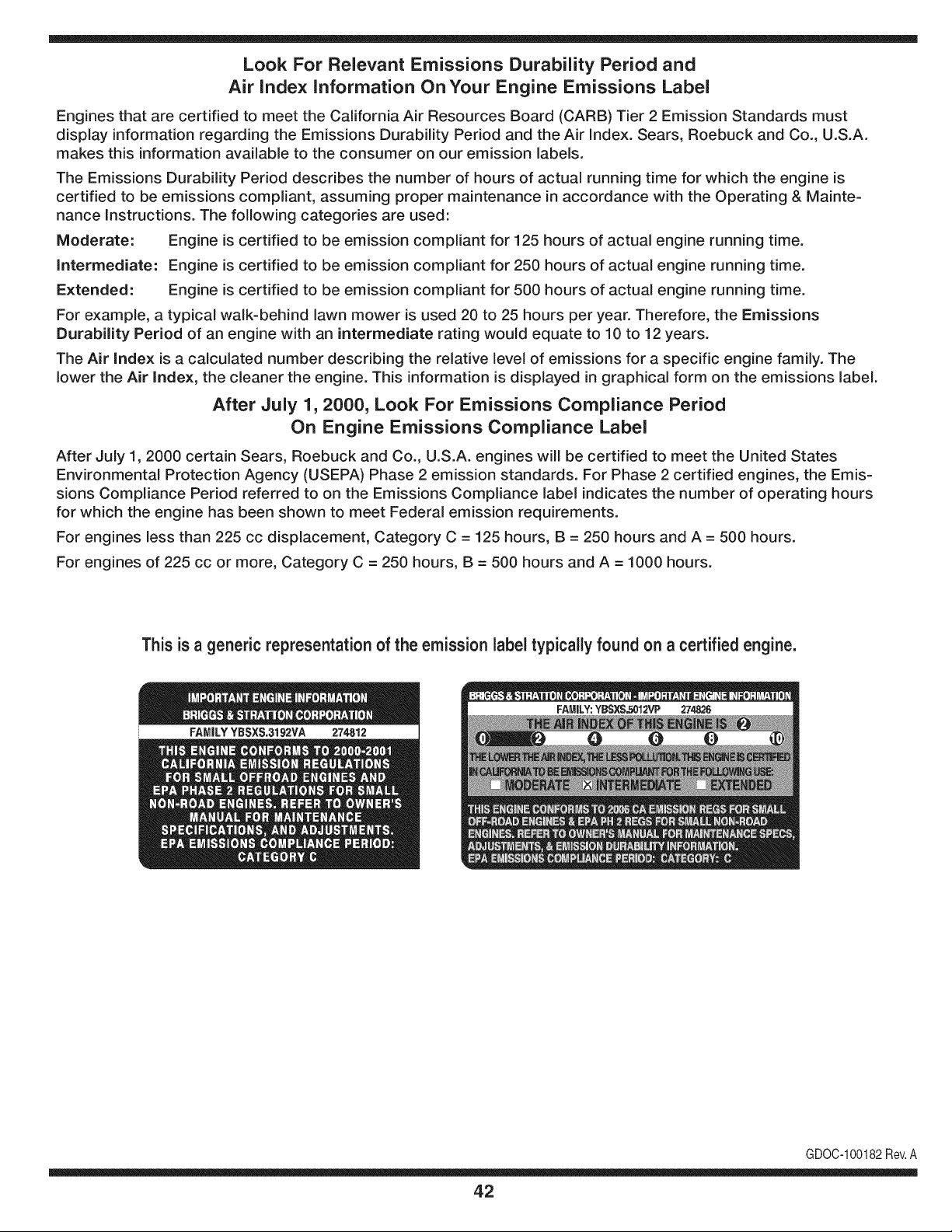
Look For Relevant Emissions Durability Period and
Air index information On Your Engine Emissions Label
Engines that are certified to meet the California Air Resources Board (CARB) Tier 2 Emission Standards must
display information regarding the Emissions Durability Period and the Air Index. Sears, Roebuck and Co., U.S.A.
makes this information available to the consumer on our emission labels.
The Emissions Durability Period describes the number of hours of actual running time for which the engine is
certified to be emissions compliant, assuming proper maintenance in accordance with the Operating & Mainte-
nance Instructions. The following categories are used:
Moderate: Engine is certified to be emission compliant for 125 hours of actual engine running time.
Intermediate: Engine is certified to be emission compliant for 250 hours of actual engine running time.
Extended: Engine is certified to be emission compliant for 500 hours of actual engine running time.
For example, a typical walk-behind lawn mower is used 20 to 25 hours per year. Therefore, the Emissions
Durability Period of an engine with an intermediate rating would equate to 10 to 12 years.
The Air Index is a calculated number describing the relative level of emissions for a specific engine family. The
lower the Air Index, the cleaner the engine. This information is displayed in graphical form on the emissions label.
After July 1,2000, Look For Emissions Compliance Period
On Engine Emissions Compliance Label
After July 1, 2000 certain Sears, Roebuck and Co., U.S.A. engines will be certified to meet the United States
Environmental Protection Agency (USEPA) Phase 2 emission standards. For Phase 2 certified engines, the Emis-
sions Compliance Period referred to on the Emissions Compliance label indicates the number of operating hours
for which the engine has been shown to meet Federal emission requirements.
For engines less than 225 cc displacement, Category C = 125 hours, B = 250 hours and A = 500 hours.
For engines of 225 cc or more, Category C = 250 hours, B = 500 hours and A = 1000 hours.
This is a generic representation of the emission label typically found on a certified engine.
FAMILYYBSXS.3192VA 274812
GDOC-100182Rev.A
42

43
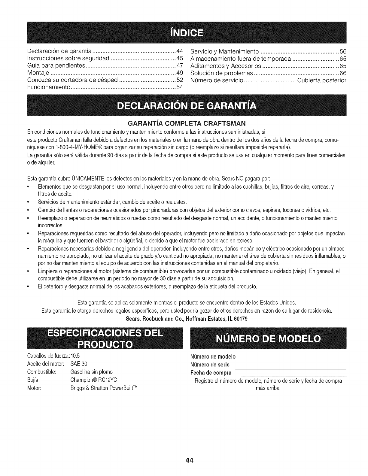
Declaraci6n de garant[a .................................................. 44
Instrucciones sobre seguridad ....................................... 45
Guia para pendientes ...................................................... 47
Montaje ........................................................................... 49
Conozca su cortadora de cesped .................................. 52
Funcionamiento ............................................................... 54
Servicio y Mantenimiento ............................................... 56
Almacenamiento fuera de temporada ............................ 65
Aditamentos y Accesorios .............................................. 65
Solucion de problemas ................................................... 66
NL_merode servicio ............................... Cubierta posterior
GARANTiA COMPLETA CRAFTSMAN
Encondicionesnormalesde funcionamientoy mantenimientoconformea ias instruccionessuministradas,si
esteproductoCraftsmanfalladebidoa defectosen los materialeso en lamanodeobradentrode losdos aSosde la fechadecompra,cornu-
niquesecon 1-800-4-MY-HOME®paraorganizarsu reparaci6nsincargo (oreemplazosi resultaraimposiblerepararla).
Lagaranfias61oser&v&lidadurante90 dias a partirde la fechade cornprasi esteproductose usaen cualquiermomentoparafinescomerciales
o dealquiler.
EstagaranfiacubreONICAMENTElos defectosenlos materialesyen la manode obra. SearsNOpagar_,por:
• Eiementosquese desgastanpot el usonormal,incluyendoentreotrosperono limitadoalas cuchillas,buj[as,filtrosdeaire,correas,y
filtrosdeaceite.
• Serviciosde mantenimientoest_.ndar,cambiode aceiteo reajustes.
• CambiodeIlantaso reparacionesocasionadospor pinchadurasconobjetosdel exteriorcomociavos,espinas,toconeso vidrios,etc.
• Reemplazoo reparaci6nde neum_.ticoso ruedascomo resultadodeldesgastenormal,unaccidente,o funcionamientoo mantenimiento
incorrectos.
• Reparacionesrequeridascomoresultadodel abusodel operador,incluyendopero no limitadoa da_o ocasionadopot objetosque impactan
la m_.quinay quetuercenel bastidoro cigOe_al,o debido a que el motorfue aceleradoen exceso.
• Reparacionesnecesariasdebidoa negligenciadel operador,incluyendoentreotros,da_osmec_.nicoy ei_ctricoocasionadopot un almace-
namientono apropiado,no utilizarel aceitede gradoy/o cantidadno apropiada,nomantenerel _.reade cubiertasin residuosinflamables,o
pot nodar mantenimientoai equipodeacuerdocon las instruccionescontenidasen el manualdei propietario.
• Limpiezao reparacionesal motor(sistemade combustible)provocadasporun combustiblecontaminadouoxidado(viejo).Engeneral,el
combustibledebeutilizarseen unper[odono mayorde 30d[asa partirde su adquisici6n.
• Eideterioroy desgastenormalde losacabadosexteriores,o reemplazode laetiquetadel producto.
Estagaranfiaseaplica solamentemientrasel productose encuentredentrodelos EstadosUnidos.
Estagaranfialeotorgaderechoslegalesespecificos,peroustedpodriagozarde otrosderechosen raz6nde su lugarde residencia.
Sears, Roebuck and Co., Hoffman Estates, IL 60179
Caballosde fuerza:10.5
Aceitedel motor: SAE30
Combustible: Gasolinasin plomo
Bujia: Champion®RC12YC
Motor: Briggs& StrattonPowerBuiltTM
NSmerode rnodelo
NSmerode serie
Fechade compra
Registreel nQmerodemodelo,nQmerode seriey fechade compra
mAsarriba.
44
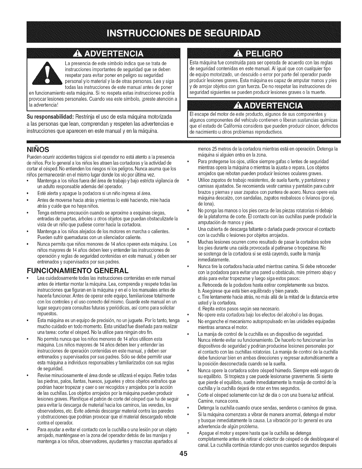
La presenciade estesimbolo indicaque se trata de
instruccionesimportantesde seguridadquese deben
respetarpara evitar poneren peligrosu seguridad
personaly/o materialy lade otras personas.Leay siga
todas las instruccionesde este manualantesde poner
en funcionamientoesta m&quina.Si no respetaestas instruccionespodria
provocarlesionespersonales.Cuando vea estesimbolo, ipresteatenci6na
la advertencia!
Su responsabilidad:Restrinjael usode esta rn_.quinarnotorizada
a las personasque lean,cornprendany respetenlas advertenciase
instruccionesqueaparecenen este manualy en la rn&quina.
Estam&quinafueconstruidapara ser operadade acuerdocon las reglas
de seguridadcontenidasen este manual.AI igual quecon cualquiertipo
de equipo motorizado,un descuido o error por partedel operadorpuede
producir lesionesgraves.Esta m&quinaes capazde amputarmanosy pies
y dearrojar objetoscon granfuerza. Deno respetarlas instruccionesde
seguridadsiguientesse puedenproducirlesionesgraveso la muerte.
Elescapedel motorde este producto,algunosde suscomponentesy
algunoscomponentesdelvehiculocontieneno liberansustanciasquimicas
que elestado de Californiaconsideraque puedenproducirc_ncer,defectos
de nacimientou otros problemasreproductivos.
N QOS
Puedenocurriraccidentestr&gicossieloperadornoest_atentoa lapresencia
denifios.PorIogenerala losnifioslesatraenlascortadorasy laactividadde
cortarelcesped.No entiendenlosriesgosnilospeligros.Nuncaasumaquelos
nifiospermanecer&nenelmismolugardondelosvioporQltimavez.
• Mantengaa losnifiosfueradel&readetrabajoy bajoestrictavigilanciade
unadultoresponsableadem_sdeloperador.
• Estealertayapaguelapodadorasiunnifioingresaal_rea.
• Antesde moversehaciaarrasy mientrasIoestehaciendo,mirehacia
atr_sy cuide queno hayanifios.
• Tengaextremaprecauci6ncuandose aproximea esquinasciegas,
entradasde puertas,_rbolesu otrosobjetosque puedanobstaculizarlela
vistade un nifio quepudiesecorrer haciala cortadora.
• Mantengaa los nifiosalejadosde losmotoresen marchao calientes.
Puedensufrirquemadurascon unsilenciadorcaliente.
• Nuncapermitaque nifiosmenoresde 14afios operenesta m&quina.Los
nifiosmayoresde 14 afios debenleery entenderlas instruccionesde
operaci6ny reglasde seguridadcontenidasen este manual,y debenset
entrenadosy supervisadospor suspadres.
FUNCIONAiVlIENTO GENERAL
• Leacuidadosamentetodas lasinstruccionescontenidaseneste manual
antesde intentarmontarlam&quina.Lea,comprenday respetetodaslas
instruccionesquefiguranen la m&quinayen el o losmanualesantesde
hacerlafuncionar.Antesde operareste equipo,familiaricesetotalmente
con loscontrolesy el usocorrectodel mismo.Guardeestemanualen un
lugarseguroparaconsultasfuturasy peri6dicas,asi comoparasolicitar
repuestos.
• Estam&quinaes un equipode precisi6n,no unjuguete.PorIotanto,tenga
muchocuidadoen todo momento.Estaunidadfue disefiadapararealizar
unatarea:cortarelcesped.Nola utiliceparaningL_notrofin.
• Nopermitanuncaque los nifios menoresde 14afios utilicenesta
m_quina.Los nifiosmayoresde 14afiosdebenleery entenderlas
instruccionesdeoperaci6ncontenidasen estemanual,y debenset
entrenadosy supervisadospor suspadres.$61ose debepermitirusar
estam_quinaa individuosresponsablesy familiarizadosconsusreglas
de seguridad.
• Reviseminuciosamenteel &teadondese utilizar&el equipo.Retiretodas
laspiedras,palos,Ilantas,huesos,juguetesyotrosobjetosextrafiosque
podrianhacertropezary caero set recogidosy arrojadospor laacci6n
de lascuchillas.Los objetosarrojadospor lam_quinapuedenproducir
lesionesgraves.Planifiqueel patr6nde cortedel cespedque hade seguir
paraevitarla descargade materialhacia loscaminos,lasveredas,los
observadores,etc. Eviteadem&sdescargarmaterialcontralas paredes
y obstruccionesquepodrianprovocarqueel materialdescargadorebote
contrael operador.
• Paraayudara evitarel contactocon lacuchillao unalesi6npot unobjeto
arrojado,mantengaseen lazonadel operadordetr_sde lasmanijasy
mantengaa los nifios,observadores,ayudantesy mascotasapartadosal
45
menos25 metrosde lacortadoramientrasest_ en operaci6n.Detengala
m&quinasi alguienentraen lazona.
• Paraprotegerselosojos,utilicesiempregafaso lentesde seguridad
mientrasoperala m&quinao mientraslaajustao repara.Losobjetos
arrojadosquerebotanpuedenproducirlesionesocularesgraves.
• Utilicezapatosdetrabajoresistentes,desuelafuerte,y pantalonesy
camisasajustados.Se recomiendavestircamisay pantal6nparacubrir
brazosy piernasy usarzapatoscon punterade acero. Nuncaopereesta
m_quinadescalzo,con sandalias,zapatosresbalososo livianos(pot ej.
de Iona).
• Nopongalasmanoso los piescercade laspiezasrotatoriasnidebajo
de laplataformade corte. El contactocon las cuchillaspuedeproducirla
amputaci6nde manosy pies.
• Unacubiertade descargafaltanteo dafiadapuedeprovocarel contacto
con la cuchillao lesionespot objetosarrojados.
• Muchaslesionesocurrencomoresultadode pasarla cortadorasobre
lospiesduranteunacaida provocadaal patinarseo tropezarse.No
se sostengade la cortadorasi seest_ cayendo,sueltela manija
inmediatamente.
• Nuncatire la cortadorahaciaustedmientrascamina.Si deberetroceder
con la podadoraparaevitarunaparedu obst&culo,mireprimeroabajoy
atr_s paraevitartropezarsey luegosiga estospasos:
a. Retrocedade la podadorahastaestirarcompletamentesus brazos.
b.AsegOresequeest&bienequilibradoy bienparado.
c.Tire lentamentehaciaarras,no m_sall_de la mitadde la distanciaentre
ustedy lacortadora.
d. Repitaestos pasossegL_nsea necesario.
• Noopereestacortadorabajolosefectosdelalcoholo lasdrogas.
• Noengancheel mecanismoautopropulsadoen las unidadesequipadas
mientrasarrancael motor.
• La manijade controlde la cuchillaes un dispositivode seguridad.
Nuncaintenteevitarsufuncionamiento.De hacerlonofuncionarianlos
dispositivosde seguridady podrianproducirselesionespersonalespor
el contactoconlascuchillasrotatorias.La manijade controlde la cuchilla
debefuncionarbienen ambasdireccionesy regresarautom_ticamentea
laposici6ndesconectadacuandose lasuelta.
• Nuncaoperela cortadorasobrecespedhOmedo.Siempreeste segurode
su equilibrio.Sitropiezay cae puedelesionarsegravemente.Sisiente
que pierdeelequilibrio,suelteinmediatamentela manijade controlde la
cuchillayla cuchilladejar&derotarentres segundos.
• Corteel cespedsolamentecon luzde dia o con unabuenaluzartificial.
Camine,nuncacorra.
• Detengala cuchillacuandocrucesendas,senderoso caminosde grava.
• Si la m_quinacomenzaraavibrar de maneraanormal,detengael motor
y busqueinmediatamentelacausa.La vibraci6npotIo generales una
advertenciade algOnproblema.
• Apagueelmotory esperehastaque lacuchillasedetenga
completamenteantesde retirarel colectorde cespedo dedesbloquearel
canal.La cuchillacontinOarotandopot unoscuantossegundosdespues
queelmotorsehaapagado.Nuncacoloqueningunapartedelcuerpoen
el_readelacuchillahastaqueesteseguroquelacuchillahadejadode
girar.
• Nuncaoperelacortadorasinotienecolocadosyfuncionandoelescudo
posteriorapropiado,lacubiertadedescarga,elcolectordecesped,
lamanijadecontroldelacuchillayotrosdispositivosdeseguridady
protecci6n.Nuncaoperelacortadorasilosdispositivosdeseguridad
est_nda_ados.SinoIohace,puedenproducirselesionespersonales.
• Elsilenciadoryelmotorsecalientanypuedencausarquemaduras.No
lostoque.
• Utilicesolamentepiezasyaccesoriosoriginalesdef_brica.SinoIohace,
puedenproducirselesionespersonales.
• Sisepresentansituacionesquenoest_nprevistasenestemanual,sea
cuidadosoyuseelsentidocomQn.Contacteconsucentrodeservicio
Searsparaobtenerayuda.
FUNCIONAIVlIENTO EN PENDIENTES
Las pendientesson un factorimportanteen losaccidentesocasionadospor
derrapesy caidasy puedenproducirlesionesgraves.La operaci6nen pendientes
requieremuchaprecauci6n.Si nose sienteseguroen unapendiente,no realice
elcorte.Parasuseguridad,useel indicadorde pendientesquese incluyecomo
partede estemanualparamedirla pendienteantesde operarla unidaden una
zonainclinada.Si lapendientesuperalos 15grados,no realiceel corte.
HagaIo siguiente:
• Corteelcespeddela pendienteen sentidotransversal,nuncahacia arriba
y abajo.Tengasumocuidadoalcambiarde direcci6nen unapendiente.
• Esteatentoa los agujeros,surcos,rocas,objetosocultoso bultosque
puedanprovocarque seresbaleo se tropiece.Elcespedaltopuede
ocultarobst&culos.
• Siempreestesegurode queest&bien afirmado.Si tropiezay cae
puedelesionarsegravemente.Si sientequepierdeel equilibrio,suelte
inmediatamentela manijade controlde la cuchillay lacuchilladejar_de
rotaren 3 segundos.
NohagaIosiguiente:
• Nocorte elcespedcercadehundimientos,zanjaso terraplenes,podria
perderelequilibrio.
• Nocorte elcespeden pendientesmayoresde 15gradoscomose muestra
en el indicadorde pendiente.
• Nocorte elcespedhQmedo.Si noest_firmementeparado,puede
resbalarse.
SERVIClO
Manejo seguro de la gasolina:
• Paraevitarlesionespersonaleso da_os materialesseasumamente
cuidadosoal manipularlagasolina.La gasolinaes sumamenteinflamable
y susvaporespuedencausarexplosiones.Si sederramagasolinaencima
o sobrela ropase puedelesionargravementeya quese puedeincendiar.
• Lavesela piely c_mbiesede ropa de inmediato.
• Utilices61olos recipientesparagasolinaautorizados.
• NuncaIlenelosrecipientesen el interiordeun vehiculoo cami6no caja
de remolquecon recubrimientospl&sticos.Antesde Ilenarlos,coloque
siemprelosrecipientesen el sueloy lejosdel vehiculo.
• Retireel equipoa gasolinadel cami6no remolquey Ileneloen elsuelo.Si
estonoes posible,Ileneelequipoen un remolquecon contenedorport_til,
en vezde desdeunaboquilladispensadorade gasolina.
• Mantengalaboquilla en contactocon elhordedel dep6sitode
combustibleo con laaberturadel recipienteen todo momento,hasta
terminarde cargar.Noutiliceun dispositivopara abrir/cerrarla boquilla.
• Apaguetodosloscigarrillos,cigarros,pipas y otrasfuentesde
combusti6n.
• Nuncacarguecombustibleen la m&quinaen interioresporquelosvapores
inflamablespodrianacumularseen el _rea.
• Nuncasaquelatapa de lagasolinaniagreguecombustiblemientrasel
motorest&calienteo en marcha. Permitaqueel motorse enfriepot Io
menosdos minutosantesdevolvera cargarcombustible.
• NuncaIleneen excesoel dep6sitode combustible.Lleneel tanquea no
m&sde Y2pulgadapor debajode la basedel cuellodeltap6n de carga,
parapermitirla expansi6ndel combustible.
• Vuelvaa colocarla tapa de la gasolinay ajL]stelabien.
• Limpiela gasolinaquese puedahaberderramadosobreel motoro el
equipo.Trasladela m_quinaaotra zona.Espere5 minutosantesde
encenderel motor.
• Nuncaalmacenela m_quinao el recipientede combustibleen un
espaciocerradodondehayafuego,chispaso aparatosconpilotocomo
porejemplo,calentadoresde agua,calefactores,hornos,secadoresde
ropau otrosaparatosa gas.
• Parareducirel riesgode incendiomantengalam_quinalimpia
de pasto,hojasy de acumulaci6ndeotros escombros.Limpie
losderramesde aceiteo combustibley saquetodos losresiduos
embebidosde combustible.
• Permitaque lam_quinase enfriepot Iomenos5 minutosantesde
almacenarla.
Servicio general:
• Nuncaenciendael motorenespacioscerradoso en unazonacon poca
ventilaci6n.El escapedel motorcontienemon6xidodecarbono,un gas
inodoroy letal.
• Antesde limpiar,repararo inspeccionarla m&quina,compruebe
que lacuchillay todaslas partesquese muevense hallandetenido.
Desconecteel cablede labujia y p6ngalohaciendomasacontrael
motorparaevitarquese enciendaaccidentalmente.
• Reviselospernosde montajede lacuchillay del motora intervalos
frecuentesparaverificarqueestenbien apretados.Inspeccione
adem&svisualmentela cuchillaen buscadedaSos(abolladuras,
desgaste,roturas,etc).Reemplacela cuchillaQnicamentecon equipo
originaldelfabricante(OEM)listadoeneste manual,i EIuso de piezas
que no cumplencon lasespecificacionesdel equipooriginalpodria
tenet comoresultadoun rendimientoincorrectoy adem_sponeren
riesgola seguridadk
• Lascuchillasde lascortadorassonmuy afiladasy podriancortarlo.
Envuelvala cuchillao utiliceguantesy extremelasprecauciones
cuandoefectQemantenimiento.
• Mantengatodoslospernos,tuercasy tornillosbienajustadospara
asegurarsede quela m_quinaseencuentraen condicionessegurasde
operaci6n.
• Nuncaintentealterarlosdispositivosde seguridad.Controle
peri6dicamentequefuncionencorrectamente.
• Despuesde golpearalgQnobjetoextraSo,detengael motor,
desconecteelcable de la bujiay col6quelohaciendomasacontrael
motor.Inspeccioneminuciosamentela m_quinaparadeterminarsi est_
daSada.RepareeldaSoantesdeencenderlay operarla.
• Nuncaintenteajustarunaruedao laaltura de cortemientrasel motor
est&en marcha.
• Loscomponentesdel colectorde cesped,la cubiertadedescargay el
escudoposterior,est&nsujetosa desgastey daSosquepodriandejar
expuestaslaspiezasm6vileso permitirquese arrojenobjetos.Para
protegersu seguridad,verifiquefrecuentementetodosloscomponentes
y reempl_celosinmediatamentes61ocon piezasde losfabricantes
del equipooriginal,listadosen estemanual,iEIuso depiezasque
nocumplenconlas especificacionesdel equipooriginalpodriatener
comoresultadoun rendimientoincorrectoyadem_sponerenriesgola
seguridadk
• Nocambiela configuraci6ndelreguladordel motorniexcedala
velocidaddel mismo.El reguladorcontrolalavelocidadm_ximasegura
de funcionamientodel motor.
• Mantengao reemplacelasetiquetasdeseguridad,segQnsea
necesario.
• Respetelasleyesy normasaplicablesparadisponeradecuadamente
de losdesechos.La disposici6ninapropiadadeliquidoso materiales
puededaSarel medioambiente.
46
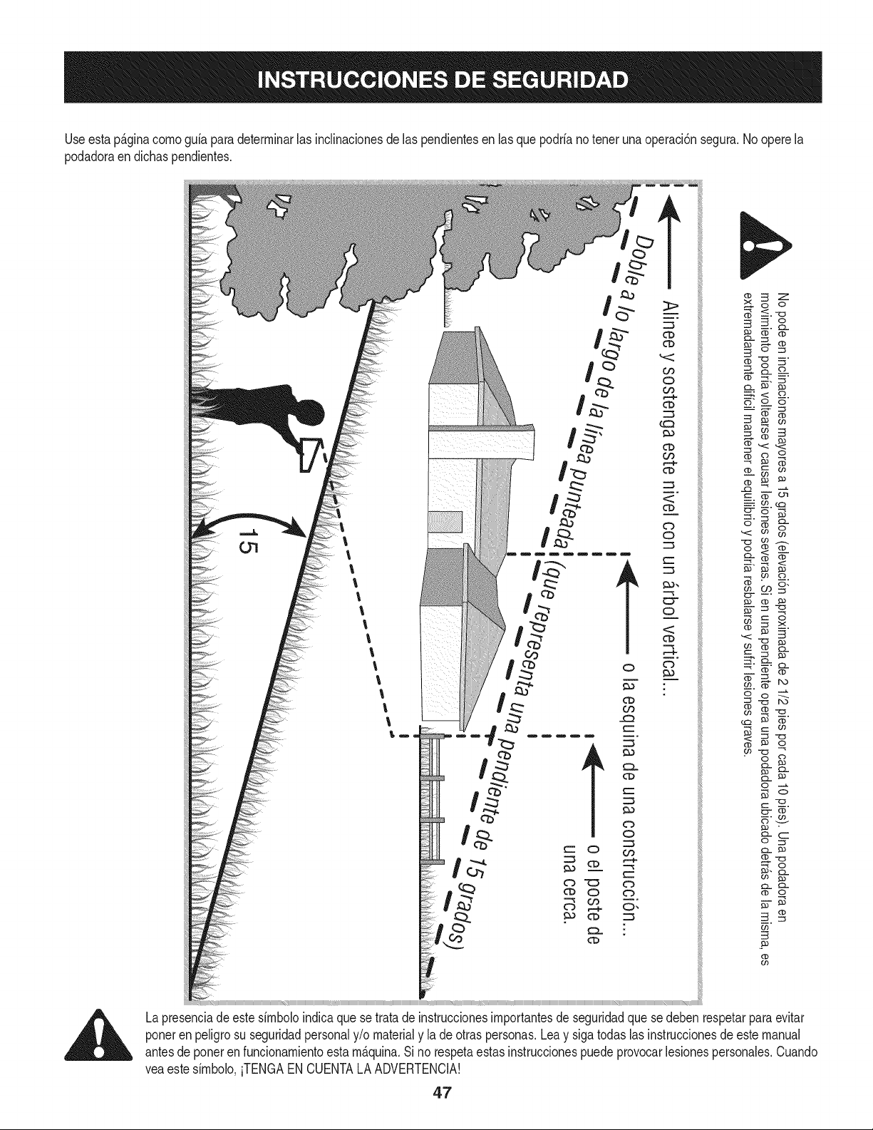
Useesta p_.ginacomoguia paradeterminarlas inclinacionesde las pendientesen las quepodrianotenerunaoperaci6nsegura.Noopere la
podadoraen dichaspendientes.
Lapresenciade estesimboloindicaquese tratadeinstruccionesimportantesde seguridadque se debenrespetarparaevitar
poneren peligrosu seguridadpersonaly/o materialy la deotraspersonas.Leay sigatodaslas instruccionesde este manual
antesde poneren funcionamientoesta m_.quina.Si no respetaestasinstruccionespuedeprovocarlesionespersonales.Cuando
veaestesimbolo,iTENGAEN CUENTALA ADVERTENCIA!
47
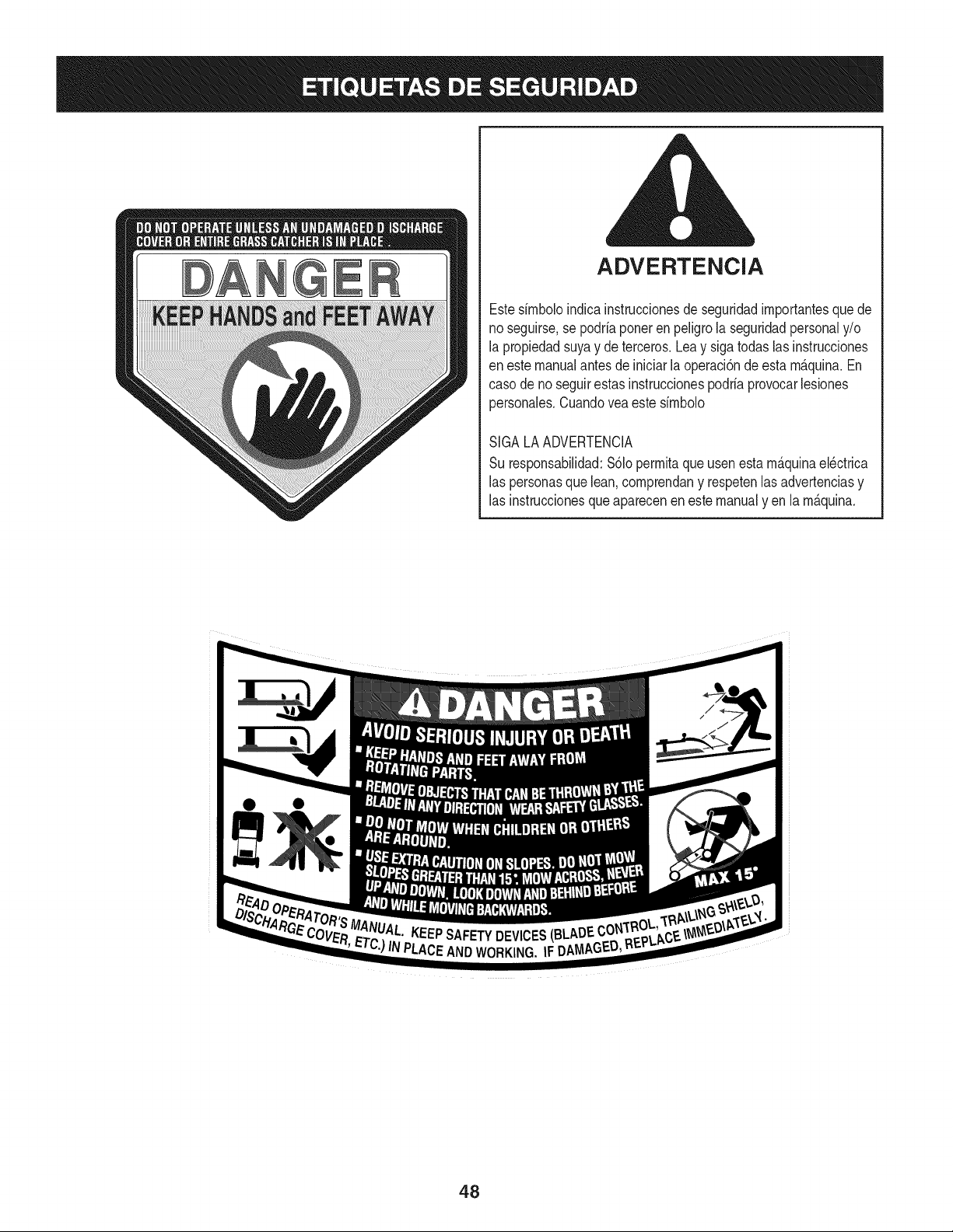
ADVERTENCIA
Estesfmboloindicainstruccionesde seguridadimportantesque de
noseguirse,se podriaponeren peligro la seguridadpersonaly/o
la propiedadsuyay de terceros.Leay sigatodas las instrucciones
eneste manualantes de iniciarla operaci6nde esta m_.quina.En
casode no seguirestasinstruccionespodriaprovocarlesiones
personales.Cuandoveaeste simbolo
SIGALAADVERTENCIA
Su responsabilidad:S61opermitaqueusenestam_.quinael_ctrica
las personasque lean,comprendany respetenlas advertenciasy
las instruccionesqueaparecenen estemanualyen la m_.quina.
48

Estapgtginasemarch6intencionadamenteenblanco.
49
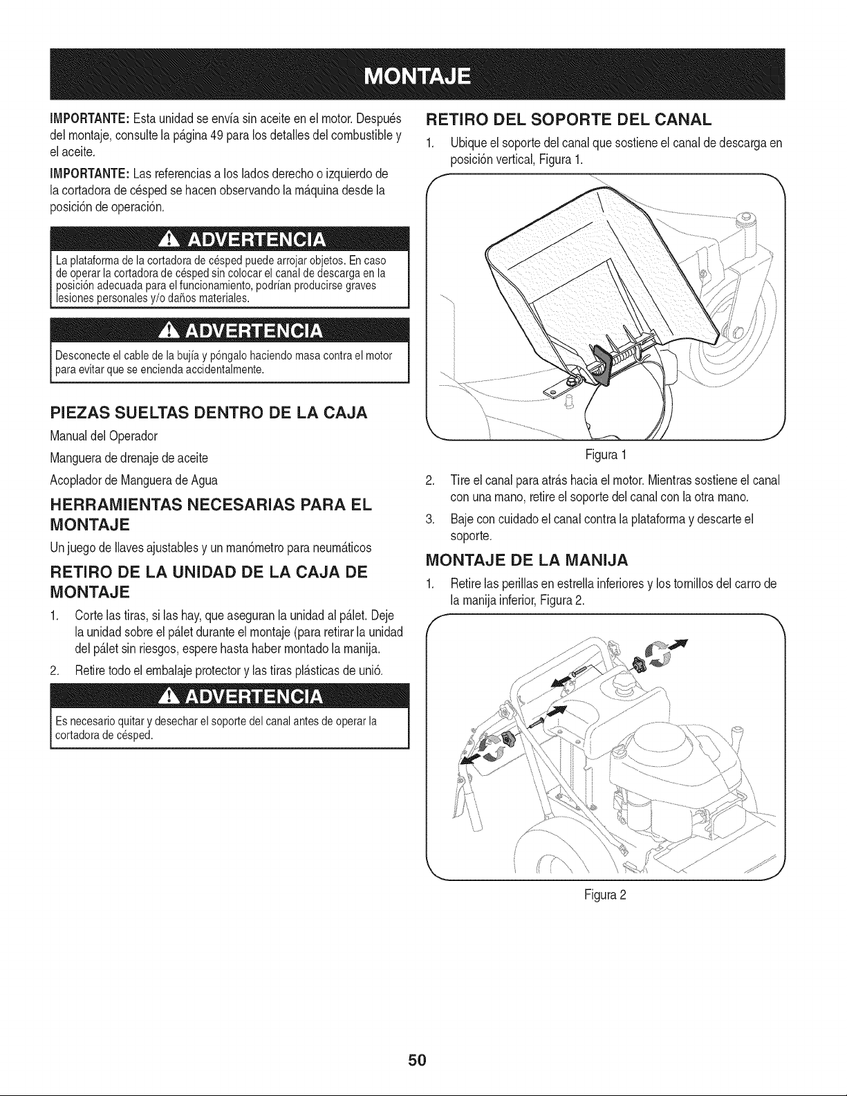
IMPORTANTE:Estaunidadse enviasin aceiteenel motor.Despu_s
delrnontaje,consultela p&gina49para los detallesdel combustibley
elaceite.
IMPORTANTE:Las referenciasa losladosderechoo izquierdode
lacortadorade c_spedse hacenobservandola rn_.quinadesdela
posici6ndeoperaci6n.
La plataformade la cortadoradecesped puedearrojarobjetos. En caso
de operarla cortadorade cesped sincolocar el canal de descargaen la
posici6nadecuadapara elfuncionamiento,podrianproducirsegraves
lesionespersonalesy/o daSosmateriales.
Desconecteel cable de la bujia y p6ngalohaciendomasacontrael motor
para evitarquese enciendaaccidentalmente.
PIEZAS SUELTAS DENTRO DE LA CAJA
Manualdel Operador
Manguerade drenajedeaceite
Acopladorde Manguerade Agua
HERRAIVIIENTAS NECESARIAS PARA EL
MONTAJE
Unjuegode Ilavesajustablesy unrnan6rnetropara neurnAticos
RETIRO DE LA UNIDAD DE LA CAJA DE
MONTAJE
1. Corte lastiras, si las hay,que aseguranla unidadal p_.let.Deje
la unidadsobreelp_.letduranteel rnontaje(para retirarla unidad
delp_.letsin riesgos,esperehastahaberrnontadolarnanija.
2. Retiretodoel ernbalajeprotectory las tiraspl_sticasde uni&
Es necesarioquitar y desecharel soporte del canalantesde operar la
cortadorade cesped.
RETIRO DEL SOPORTE DEL CANAL
1. Ubiqueel soportedel canalque sostieneel canalde descargaen
posici6nvertical,Figura1.
f
Figura1
2. Tire el canal paraatr_.shaciael motor.Mientrassostieneel canal
con unarnano,retireel soportedelcanalcon la otrarnano.
3. Bajecon cuidadoel canalcontrala plataforrnay descarteel
soporte.
MONTAJE DE LA MANIJA
1. Retirelas perillasen estrellainferioresy lostornillosdel carrode
la rnanijainferior,Figura2.
Figura2
50
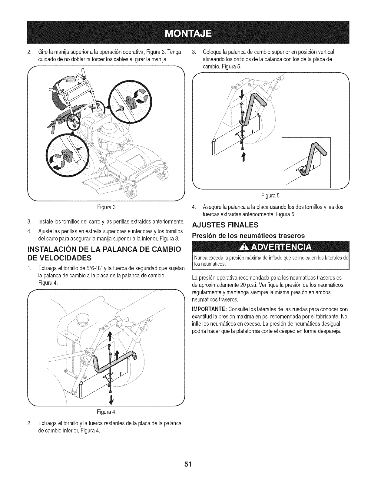
2. Gire la manijasuperiora la operaci6noperativa,Figura3. Tenga
cuidadode nodoblar ni torcer loscables al girar la manija.
3. Coloquela palancade cambiosuperioren posici6nvertical
alineandolosorificiosdela palancacon los de laplacade
cambio,Figura5.
/
/
/
J
Figura3
3. Instalelostornillosdel carro y las perillasextraidosanteriormente.
4. Ajustelas perillasen estrellasuperiorese inferioresy los tornillos
delcarroparaasegurarla manijasuperiora la inferior,Figura3.
INSTALACION DE LA PALANCA DE CAMBIO
DE VELOCIDADES
Extraigaeltornillode 5/6-18"y latuercade seguridadquesujetan
la palancadecambioa la placade lapalancadecambio,
Figura4.
,
Figura4
Extraigaeltornilloy la tuerca restantesdela placade lapalanca
decambioinferior,Figura4.
Figura5
4. Asegurela palancaa la placausandolosdos tornillosy las dos
tuercasextraidasanteriormente,Figura5.
AJUSTES FINALES
Presi6n de los neumaticos traseros
Nuncaexcedala presi6nm_ximade infladoquese indica enlos lateralesde
los neum_ticos.
Lapresi6noperativarecomendadaparalos neum_.ticostraseroses
de aproximadamente20 p.s.i.Verifiquela presi6nde los neum_.ticos
regularmentey mantengasiemprela mismapresi6nen ambos
neum_.ticostraseros.
IMPORTANTE:Consultelos lateralesde las ruedasparaconocercon
exactitudlapresi6nm_.ximaen psi recomendadapor el fabricante.No
inflelos neum_.ticosenexceso.La presi6nde neum_.ticosdesigual
podriahacerquela plataformacorte el cespeden formadespareja.
51
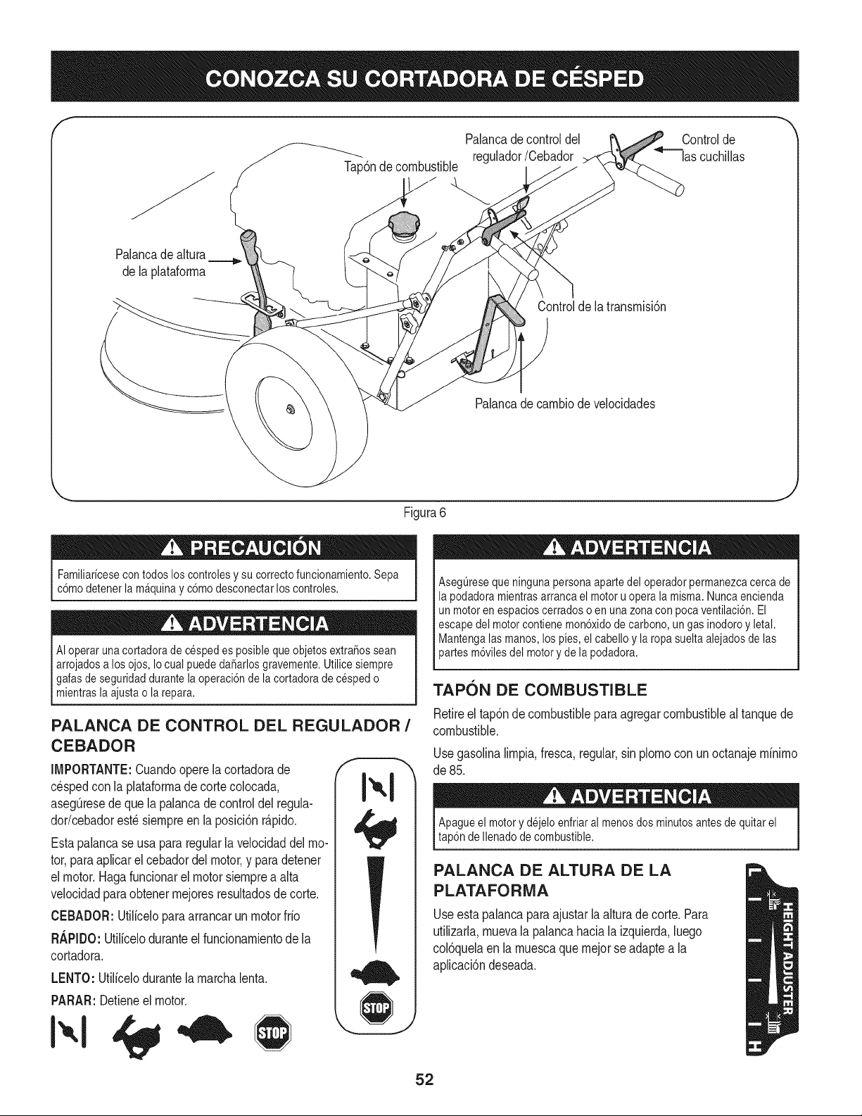
Tap6nde combustible
Palancadecontrol del
regulador/Cebador
Controlde
las cuchillas
Palancadealtura
dela plataforma
Controlde la transmisi6n
Palancade cambiodevelocidades
Figura6
Familiaricesecon todoslos controlesy su correctofuncionamiento.Sepa
c6mo detenerla m4quinayc6mo desconectarlos controles.
AIoperarunacortadorade cespedes posibleque objetosextra_ossean
arrojadosa los ojos,Iocual puededa_arlosgravemente.Utilicesiempre
I galasde seguridaddurante la operaci6nde la cortadoradecesped o
mientraslaajustao larepara.
PALANCA DE CONTROL DEL REGULADOR /
CEBADOR
IMPORTANTE:Cuandooperela cortadorade
cespedcon la plataformade corte colocada,
asegQresedequela palancade controldel regula-
dor/cebadorest6 siempreen la posici6nr&pido.
Estapalancase usa pararegularla velocidaddel mo-
tor,paraaplicarel cebadordel motor,y paradetener
el motor.Hagafuncionarel motorsiemprea alta
velocidadpara obtenermejoresresultadosde corte.
CEBADOR:Utiliceloparaarrancarunmotorfrio
R._PIDO:Utiliceloduranteel funcionamientode la
cortadora.
LENTO: Utilicelodurantela marchalenta.
PARAR: Detieneel motor.
AsegQreseque ningunapersonaaparte del operadorpermanezcacerca de
la podadoramientrasarrancael motoru opera la misma.Nuncaencienda
un motoren espacioscerradoso en una zonacon pocaventilaci6n. El
escapedel motorcontienemon6xidode carbono,un gas inodoroy letal.
Mantengalasmanos, los pies, el cabelloy la ropa sueltaalejadosde las
)artes m6vilesdel motory de la podadora.
TAPON DE COMBUSTIBLE
Retireel tap6nde combustiblepara agregarcombustibleal tanquede
combustible.
Usegasolinalimpia,fresca,regular,sin plomocon unoctanajeminimo
de 85.
Apagueel motory dejeloenfriaral menosdos minutosantesde quitar el
tap6nde Ilenadode combustible.
PALANCA DE ALTURA DE LA
PLATAFORMA
Useestapalancaparaajustar la alturade corte. Para
utilizarla,muevala palancahaciala izquierda,luego
col6quelaen la muescaque mejorseadaptea la
aplicaci6ndeseada.
52
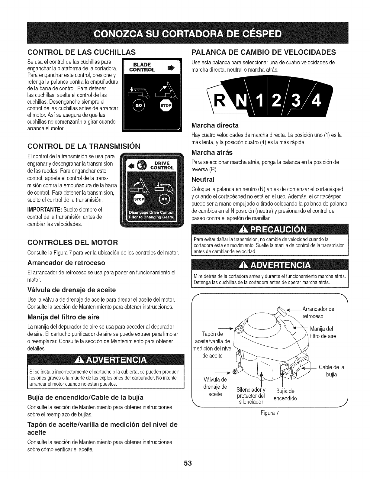
CONTROL DE LAS CUCHILLAS
Seusa elcontrolde las cuchillaspara
engancharla plataforrnade lacortadora.
Paraengancharestecontrol,presioney
retengala palancacontrala ernpu_adura
dela barrade control.Paradetener
las cuchillas,suelteel controlde las
cuchillas.Desenganchesiernpreel
controlde lascuchillasantesde arrancar
el motor.Asi se aseguradequelas
cuchillasnocornenzar_.na girar cuando
arrancael motor.
CONTROL DE LA TRANSMISION
Elcontrolde la transrnisi6nse usa para
engranary desengranarla transrnisi6n
delas ruedas.Paraenganchareste
control,aprieteelcontrolde la trans-
rnisi6ncontrala ernpu_aduradela barra
decontrol.Paradetenerla transrnisi6n,
suelteel controlde la transrnisi6n.
IMPORTANTE:Sueltesiernpreel
controlde la transrnisi6nantesde
carnbiarlasvelocidades.
PALANCA DE CAMBIO DE VELOCIDADES
Useestapalancaparaseleccionaruna de cuatrovelocidadesde
rnarchadirecta,neutralo rnarchaatr_.s.
IVlarcha directa
Haycuatrovelocidadesde rnarchadirecta.La posici6nuno (1)es la
rn_.slenta,y la posici6ncuatro(4) es larn_.sr_.pida.
Marcha arras
Paraseleccionarrnarchaatr_.s,pongala palancaen la posici6nde
reversa(R).
Neutral
Coloquelapalancaen neutro(N) antesde cornenzarel cortac_sped,
y cuandoel cortacespedno est,. en el uso. Adern_.s,el cortac_sped
puedesera rnanoernpujadoo tiradocolocandola palancade palanca
de carnbiosen el N posici6n(neutra)y presionandoelcontrolde
paseocontrael apret6nde rnanillar.
CONTROLES DEL MOTOR
Consultela Figura7 paraverla ubicaci6nde los controlesdel motor.
Arrancador de retroceso
Elarrancadorde retrocesose usa paraponerenfuncionarnientoel
motor.
Valvula de drenaje de aceite
Usela v_.lvulade drenajede aceiteparadrenarel aceitedel motor.
Consultela secci6nde Mantenirnientoparaobtenerinstrucciones.
IVlanija del filtro de aire
La rnanijadel depuradorde airese usa paraaccederal depurador
deaire. Elcartuchopurificadorde airese puedeextraerparalirnpiar
o reernplazar.Consultela secci6nde Mantenirnientoparaobtener
detalles.
Si se instala incorrectamenteel cartuchoo la cubierta,se pueden producir
lesionesgraveso la muertede lasexplosionesdel carburador.No intente
arrancar el motorcuandono est_n puestos.
Bujia de encendido/Cable de la bujia
Consultela secci6nde Mantenirnientoparaobtenerinstrucciones
sobreel reernplazode bujias.
Tap6n de aceite/varilla de medici6n del nivel de
aceite
Consultela secci6nde Mantenirnientoparaobtenerinstrucciones
sobrec6rnoverificarel aceite.
Paraevitarda_arla transmisi6n,no cambiedevelocidadcuando la
cortadoraest_ en movimiento.Sueltela manijade control de latransmisi6n
antesde cambiarde velocidad.
Miredetr_sdelacortadoraantesy duranteelfuncionamientomarchaarras.
Detengalascuchillasdelacortadoraantesdeoperarmarchaarras.
f
de
retroceso
i.._ Manijadel
Tap6nde filtrodeaire
aceite/varillade
rnedici6ndelnivel
deaceite
V_.lvulade
drenajede
aceite
Silenciadory Bujiade
protectordel encendido
silenciador
Cablede la
bujia
Figura7
53
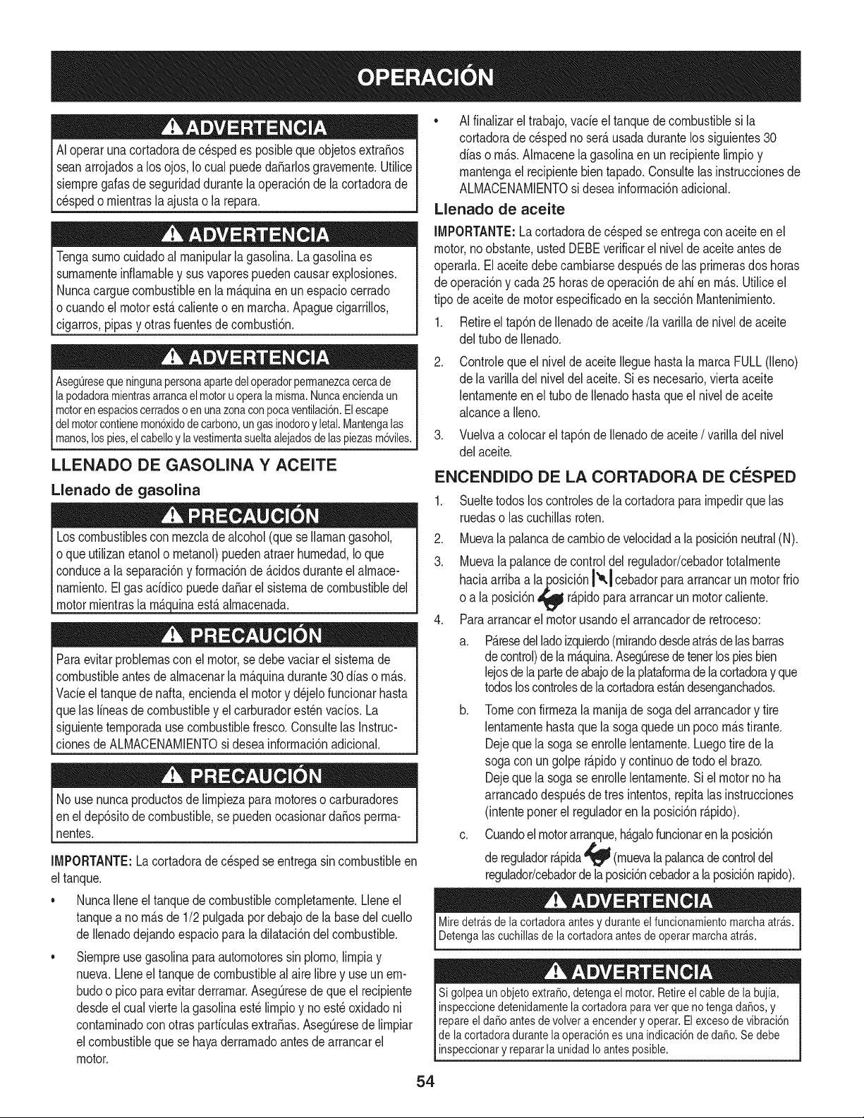
AIoperarunacortadorade cespedes posibleque objetosextra_os
seanarrojadosa los ojos,Iocual puededa_arlosgravernente.Utilice
siempregalas de seguridaddurantela operaci6nde la cortadorade
cespedo mientraslaajustao la repara.
Tengasumocuidadoal manipularlagasolina.Lagasolinaes
sumamenteinfiamabley susvaporespuedencausarexplosiones.
Nuncacarguecombustibleen la m_.quinaen unespaciocerrado
ocuandoel motorest,. calienteo en marcha.Apaguecigarrillos,
cigarros,pipasy otrasfuentesdecombusti6n.
AsegQresequeningunapersonaapartedeloperadorpermanezcacercade
la podadoramientrasarrancaelmotoruoperala misma.Nuncaenciendaun
motoren espacioscerradosoen unazonacon pocaventilaci6n.Elescape
del motorcontienemon6xidode carbono,ungasinodoroyletal.Mantengalas
manos,os pes,e cabe o y avestmentasueta ae adosde aspezas m6v es.
LLENADO DE GASOLINA Y ACEITE
Llenado de gasolina
Loscombustiblescon mezcladealcohol(quese Ilamangasohol,
oque utilizanetanolo metanol)puedenatraerhumedad,Ioque
conducea la separaci6ny formaci6nde_.cidosduranteelalmace-
namiento.Elgas addico puededa_arel sistemade combustibledel
motormientrasla m_.q_uinaest,.almacenada.
Paraevitarproblemascon el motor,se debevaciarel sistemade
combustibleantesde almacenarla m_.quinadurante30dfas o m_.s.
Vade el tanquede nafta,enciendael motory d_jelofuncionarhasta
que las lineasde combustibley el carburadorest_nvados. La
siguientetemporadausecombustiblefresco.Consultelas Instruc-
clonesde ALMACENAMIENTOsi deseainformaci6nadicional.
No usenuncaproductosde limpiezaparamotoreso carburadores
en el dep6sitode combustible,se puedenocasionarda_osperma-
nentes.
IMPORTANTE:Lacortadoradec_sped seentregasincombustibleen
eltanque.
• NuncaIleneeltanquede combustiblecompletamente.Lleneel
tanquea no m_.sde 1/2pulgadapordebajode la basedel cuello
de Ilenadodejandoespacioparala dilataci6ndel combustible.
• Siempreusegasolinaparaautomotoressinplorno,limpiay
nueva.Lleneel tanquede combustiblealairelibrey useunem-
budoo picoparaevitarderrarnar.AsegQresede queel recipiente
desdeelcual viertela gasolinaest_ limpioy no est_ oxidadoni
contaminadocon otrasparficulasextraSas.Aseg[3resede limpiar
elcombustiblequese hayaderramadoantesdearrancarel
motor.
• AI finalizareltrabajo,vacie el tanquede combustiblesi la
cortadoradec_sped no ser_.usadadurantelos siguientes30
dias o m_.s.AImacenela gasolinaenun recipientelimpioy
mantengael recipientebientapado.Consultelas instruccionesde
ALMACENAMIENTOsi desea informaci6nadicional.
Llenado de aceite
IMPORTANTE:Lacortadorade c_spedse entregacon aceiteen el
motor,noobstante,ustedDEBEverificarel nivelde aceiteantesde
operarla.Elaceitedebe cambiarsedespu_sde las primerasdos horas
de operaci6ny cada25 horasde operaci6ndeahi enm_.s.Utiliceel
tipo de aceitede motorespecificadoen lasecci6nMantenimiento.
1. Retireel tap6nde Ilenadodeaceite/la varillade nivelde aceite
del tubode Ilenado.
.
Controlequeel nivelde aceite Ileguehasta la marca FULL(lleno)
de lavarilladel niveldelaceite.Sies necesario,viertaaceite
lentamenteen el tubode Ilenadohastaqueel nivelde aceite
alcancea lien&
3. Vuelvaa colocarel tap6nde Ilenadode aceite/ varilladel nivel
del aceite.
ENCENDIDO DE LA CORTADORA DE ClaSPED
1. Sueltetodos loscontrolesde la cortadorapara impedirque las
ruedaso las cuchillasroten.
.
3.
.
Muevala palancade cambiodevelocidada la posici6nneutral(N).
Muevala palancede controldel regulador/cebadortotalmente
haciaarribaa la2osici6nI'_,1cebadorparaarrancarunmotorfrio
o a la posici6n_ r_.pidoparaarrancarun motorcaliente.
Paraarrancarel motorusandoel arrancadorde retroceso:
a. P_.resedelladoizquierdo(rnirandodesdeatr_.sde lasbarras
decontrol)de lam_.quina.Aseg[3resedetenerlospiesbien
lejosdela partedeabajode la plataformade la cortadoray que
todosloscontrolesdela cortadoraest_.ndesenganchados.
b. Tomecon firmezala manijade sogadel arrancadory tire
lentamentehastaquela sogaquede un pocom_.stirante.
Dejeque la sogase enrollelentamente.Luegotire dela
soga conun golper_.pidoy continuodetodo el brazo.
Dejeque la sogase enrollelentamente.Siel motornoha
arrancadodespu_sde tres intentos,repitalasinstrucciones
(intenteponerel reguladoren la posici6nr_.pido).
c. Cuandoel motorarranque,h_.galofuncionarenla posici6n
de reguladorr_.pida_ (muevalapalancadecontroldel
regulador/cebadordela posici6ncebadora la posici6nrapido).
Miredetr_sde la cortadoraantesy duranteelfuncionamientomarchaarras.
Detengalascuchillasde la cortadoraantesde operarmarchaarras.
Si golpea un objeto extra,o, detengael motor.Retireel cablede la bujia,
inspeccionedetenidamentela cortadoraparaver que no tenga da_os,y
repareel da_o antesdevolvera encendery operar.Elexcesode vibraci6n
de la cortadoradurantela operaci6nes una indicaci6nde daSo.Se debe
inspeccionary repararla unidad Ioantes posible.
54

Mire detr_sde la cortadoraantesy duranteel funcionamientomarchaarras.
Detengalas cuchillasde lacortadoraantesde operarmarchaarras.
USO DE LA CORTADORA DE CESPED
IMPORTANTE:Sueltesiernpreel controlde latransrnisi6nantesde
carnbiarlasvelocidad.Consultela secci6n"Conozcasu cortadorade
cesped"paravetlos controlesde lacortadora.
AsegOresede que el c_spedesta librede piedras,palos,cables u
otrosobjetosquepudiesendaSarla cortadorao el motor.Dichos
objetospuedenserarrojadosaccidentalrnentepot la cortadoraen
cualquierdirecci6ny provocarlesionespersonalesgravesal operador
y a otraspersonas.Paraobtenerrnejoresresultados,no cortec_sped
rnojadoy nuncacorte rn_sde un tercio de la Iongitudtotaldel c_sped.
1. Unavez que el motorest_ funcionando,aprieteel controlde
transrnisi6ncontrala rnanijasuperiorparairnpulsarlarn_.quina.
Paraactivarlas cuchillasdecorte,aprieteel controldelas
cuchillascontrala rnanijasuperior.
2. Paracarnbiardevelocidad,liberelapalancadecontrolde la
transrnisi6ny rnuevalapalancadecarnbiode velocidada laposici6n
deseada.Parapracticarconla cortadorainicialrnente,pongala
palancaen la posici6nNO1.Seleccionelasvelocidadesdirectas
segOnlascondicionesdelterrenoy del corte.Usevelocidades
rn_.sbajasenterrenosagrestesodondeelpastoes rn_.spesado
ogrueso.Lavelocidaddirectase puedeaurnentarsobreterrenos
lisoso dondeelpastonoestarnuytupido.Perrnitaquelasruedasse
detengancornpletarnenteantesdecarnbiarde unavelocidada otra.
IMPORTANTE:Tengapresenteque al engancharla palancade
controlde la transrnisi6ncon lapalancade carnbioen 3ra o 4ta
velocidad,la potenciay el par motorgeneradospuedenhacerque la
unidadse sacudahaciaadelante.Para evitarlo,aprietelentarnentela
palancade controldela transrnisi6ncontrala rnanijasuperior.
3. Paradetenerlascuchillas,suelteel controlde lascuchillas.Para
detenerel controldela transrnisi6na las ruedas,suelteelcontrol
dela transrnisi6n.
DETENCION DE LA CORTADORA DE
CESPED
1. Suelteel controlde las cuchillasy la transrnisi6nparadetenerlas
ruedasy las cuchillasde plataforrna.
2. Muevala palancade controldel regulador/cebadorhaciaabajo
a laposici6nlenta (tortuga)_. Siernprequesea posible,
reduzcagradualrnentela velocidaddel motorantesde detenerlo.
.
.
Muevalapalancade controldel regulador/cebadortotalrnente
haciaabajoa la posici6nStop (detenci6n).
Desconecteel cabledela bujiay p6ngalohaciendornasacontra
el motor.
TRASLADO DE LA CORTADORA DE CESPED
CON EL MOTOR APAGADO
Sepuedeernpujaro tirarde la cortadorarnanualrnentecolocandola
palancadecarnbiode velocidadenlaposici6nN(neutral)y presionando
elcontrolde latransrnisi6ncontrala ernpuSadurade la barradecontrol.
ABONO O CORTE CON DESCARGA LATERAL
Sepuedeusarlacortadorade c_spedtantocornocortadoraabonadora
o cornocortadoracon descargalateral.Parausarla funci6nde abono,
insertela clavijade abonocornoseindicaacontinuaci6n.Retirela
clavijadeabonoparadescargarlateralrnentelosrecortesdecesped.
Laclavijade abonoest,. diseSadapararnantenerel canalde descarga
levantadoduranteel corte.Cuandose retiralaclavija,elcanalde
descargase bajasolopara cortarcon descargalateral.
Antes de instalaro desinstalarla clavijade abono,detengael motor,espera
a quelas piezasdejen de moversey desconecteel cablede labujia.
Parainstalaro desinstalarla clavijade abono:
1. Detengael motory esperaquetodaslas piezasdejende
rnoverse.
.
3.
.
5.
Desconecteel cablede la bujia.
Parainstalarlaclavija de abono,insertela leng(Jetaderecha(A)
de laclavijaenel soportede la plataforrna,Figura8.
Insertela cubiertaenla aberturade descarga(B), Figura8.
Unavezquela clavijade abonoest,.colocadaen laaberturade la
plataforrna,ernpQjelahacialaparteposteriorde la cortadora(C)
paraquela clavijacalcecorrectarnenteenla abertura,Figura8.
Pararetirarlaclavija,deslicela cubiertahaciala derecha(frente
de lacortadora)paradesengancharla ranurade la plataforrnade
lacortadoray luegofuerceel ladoizquierdode lacubiertahacia
afueraparasoltada.
J
Figura8
Mantengalas rnanosy piesalejadosde la aberturade descargade
laplataforrnade corte.
55
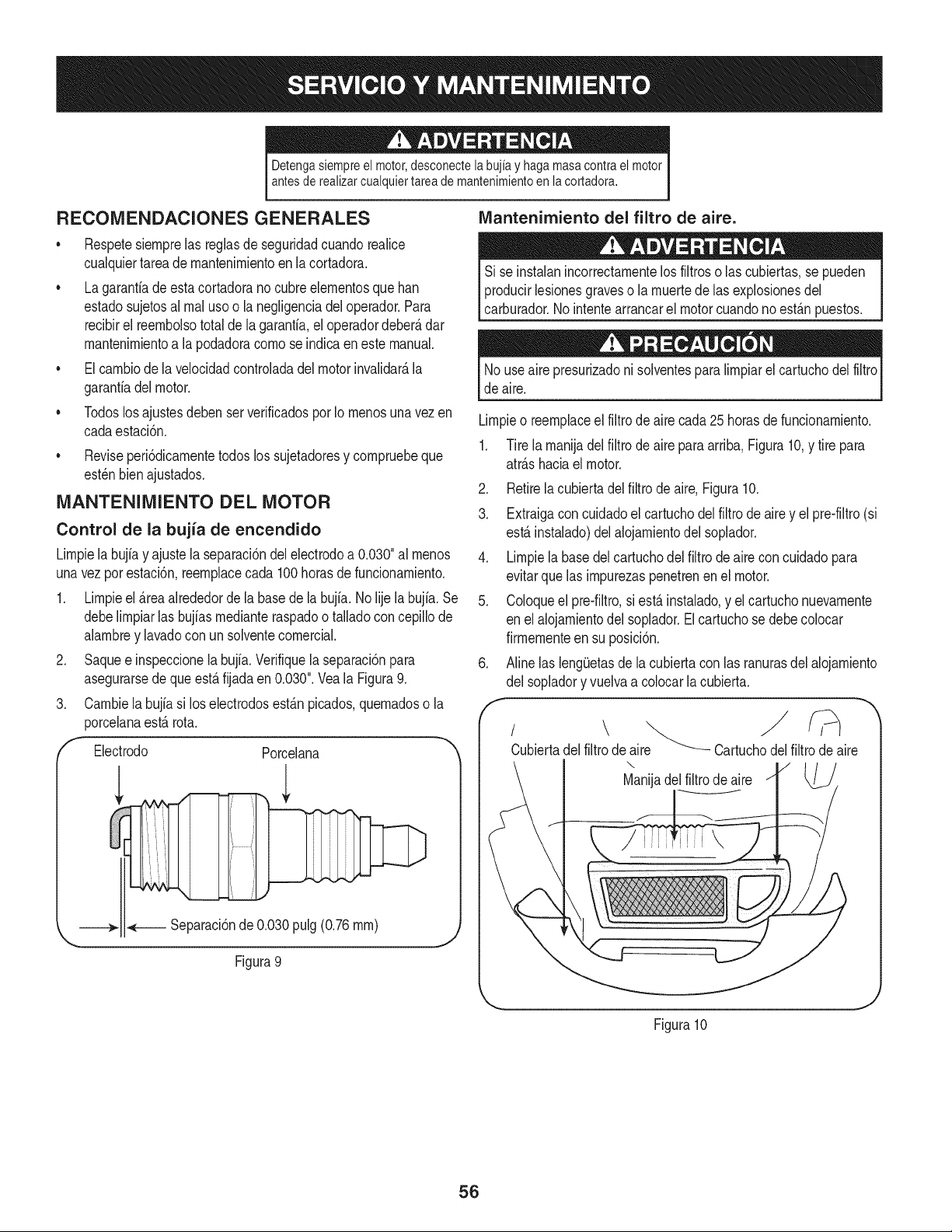
Detengasiempreel motor,desconectelabujia y haga masacontrael motor
antesde realizarcualquiertareade mantenimientoen la cortadora.
RECOMENDACIONES GENERALES
• Respetesiernprelas reglasde seguridadcuandorealice
cualquiertareadernantenirnientoenlacortadora.
• Lagaranfiade esta cortadorano cubreelernentosque ban
estadosujetosal rnal usoo la negligenciadeloperador.Para
recibirel reernbolsototalde la garanfia,el operadordeber&dar
rnantenirnientoa la podadoracornose indicaenestemanual.
• Elcarnbiode la velocidadcontroladadel motor invalidar&la
garanfiadel motor.
• Todoslosajustesdebenser verificadospor Io rnenosunavez en
cadaestaci6n.
Reviseperi6dicarnentetodoslos sujetadoresy cornpruebeque
est_nbienajustados.
MANTENIMIENTO DEL MOTOR
Control de la bujia de encendido
Lirnpielabujia y ajustela separaci6ndel electrodoa 0.030"al rnenos
unavez por estaci6n,reernplacecada 100horasde funcionarniento.
1. Lirnpieel _reaalrededorde la basede la bujia.No lije la bujia.Se
debelirnpiarlas bujiasrnedianteraspadoo talladocon cepillode
alarnbrey lavadoconun solventecornercial.
2. Saquee inspeccionela bujfa.Verifiquela separaci6npara
asegurarsede queest,. fijadaen 0.030".Veala Figura9.
3. Carnbiela bujia si loselectrodosest_.npicados,quernadoso la
porcelanaest,. rota.
f Electrodo Porcelana
_ Separaci6n de 0.030 pulg (0.76 rnrn)
Figura 9
IVlantenirniento del filtro de aire.
Si se instalanincorrectarnentelos filtroso las cubiertas,se pueden
producirlesionesgraveso la rnuertede las explosionesdel
carburador.Nointentearrancarel motorcuandono est_.npuestos.
No useairepresurizadoni solventesparalirnpiarelcartuchodelfiltro
deaire.
Lirnpieo reernplaceel filtro de aire cada25 horasde funcionarniento.
1. Tire la rnanijadelfiltrode aireparaarriba,Figura10,y tire para
atr_.shaciael motor.
2. Retirela cubiertadel filtro de aire,Figura10.
3. Extraigacon cuidadoel cartuchodel filtrodeairey el pre-filtro(si
est,.instalado)del alojarnientodel soplador.
4. Lirnpiela basedelcartuchodel filtrodeairecon cuidadopara
evitarque las irnpurezaspenetrenenel motor.
5. Coloqueel pre-filtro,si est_ instalado,y el cartuchonuevarnente
en elalojarnientodelsoplador.El cartuchose debe colocar
firrnernenteensu posici6n.
6. Aline las leng_Jetasde la cubiertacon las ranurasdel alojarniento
del sopladory vuelvaa colocarla cubierta.
Cubiertadelfiltro de aire ""-_-- Cartuchodelfiltrode aire
\
Manijadelfiltrodeaire
Figura10
J
56
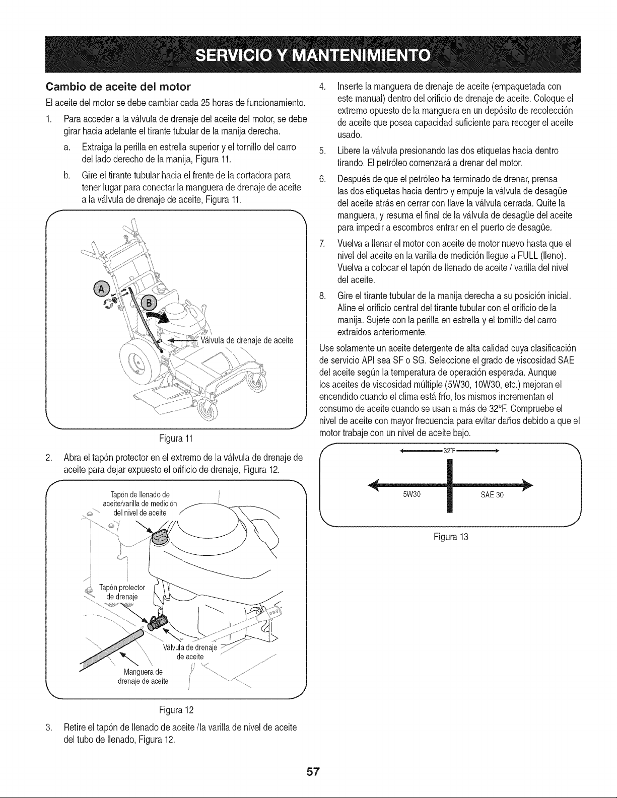
Cambio de aceite del motor
Elaceitedel motorse debecambiarcada25 horasde funcionamiento.
Paraaccedera la v_Jvulade drenajedel aceitedel motor,se debe
girarhada adelanteel firantetubularde la manijaderecha,
a, Extraigala perillaen estrellasuperiory el tornillodel carro
dellado derechode la manija,Figura11,
b, Gire el firantetubularhada el frentede la cortadorapara
tenerlugarparaconectarla manguerade drenajedeaceite
a lav_Jvulade drenajede aceite,Figura11.
f
Wlvula dedrenajede aceite
.J
Figura11
Abrael tap6nprotectoren el extremode la v_.lvuladedrenajede
aceiteparadejarexpuestoel orificiode drenaje,Figura12.
Tap6nde Ilenadode
aceite/varillade medici6n
_,_,.......... del nivelde aceite
i .....................
d_,,_Tap6nprotector
......"i_ de drenaje
.
Wlvula de drenaje
de aceite
drenajeMangueradeaceitede __ .................................................
Figura12
J
Retireel tap6ndeIlenadode aceite/la varillade niveldeaceite
deltubo deIlenado,Figura12.
Insertela manguerade drenajede aceite(empaquetadacon
estemanual)dentrodel orificio de drenajede aceite.Coloqueel
extremoopuestode la mangueraenun dep6sitode recolecci6n
de aceitequeposeacapacidadsuficientepara recogerel aceite
usado.
5. Liberela v_.lvulapresionandolas dos etiquetashaciadentro
tirando.El petr61eocomenzar_,a drenardel motor.
6. Despu_sde que el petr61eoha terminadodedrenar,prensa
lasdos etiquetashaciadentroy empujela v_.lvuladedesag_Je
del aceiteatr_.sen cerrarcon Ilavela v_Jvulacerrada.Quitela
manguera,y resumael finalde la v_.lvulade desag(Jedelaceite
paraimpediraescombrosentrarenel puertodedesag_Je.
7. Vuelvaa Ilenarel motorconaceite de motor nuevohastaque el
niveldelaceiteen la varillade medici6nIleguea FULL(lleno).
Vuelvaa colocarel tap6nde Ilenadode aceite/ varilladelnivel
del aceite.
Gireel tirantetubulardela manijaderechaa su posici6ninicial.
Alineel orificiocentraldeltirante tubularcon el orificio de la
manija.Sujetecon la perilla en estrellay el tornillodel carro
extraidosanteriormente.
Usesolamenteunaceitedetergentedealta calidadcuyaclasificaci6n
de servicioAPIsea SFo SG. Seleccioneel gradode viscosidadSAE
del aceitesegQnlatemperaturade operaci6nesperada.Aunque
losaceitesdeviscosidadmQItiple(5W30,10W30,etc.) mejoranel
encendidocuandoel clima est,. frio, los mismosincrementanel
consumode aceitecuandose usana m_.sde 32°E Compruebeel
niveldeaceitecon mayorfrecuenciaparaevitarda_osdebido a que el
motortrabajecon unnivelde aceitebajo.
Figura13
57
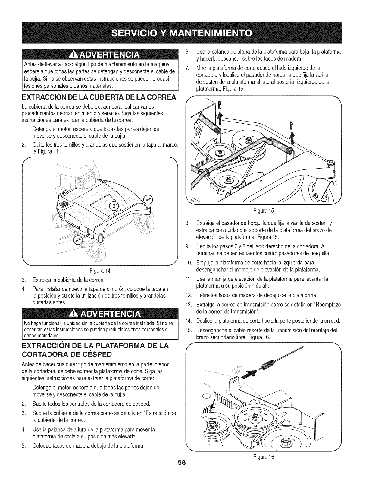
Antesde Ilevara caboalgQntipo dernantenirnientoen la rn_.quina,
esperea quetodas las partesse detengany desconecteel cablede
labujfa. Si no se observanestasinstruccionesse puedenproducir
[ esonespersonaes o da_osmatera es.
EXTRACCION DE LA CUBIERTA DE LA CORREA
Lacubiertade la correasedebeextraerpara realizarvarios
procedirnientosde rnantenirnientoy servicio.Siga las siguientes
instruccionesparaextraerla cubiertade la correa.
1. Detengael motor,espereaquetodas las partesdejende
rnoversey desconecteel cablede la bujfa.
2. Quitelos tres tornillosy arandelasque sostienenla tapaal marco,
la Figura14.
f
.
4.
J
J
Figura14
Extraigala cubiertade la correa.
Parainstalarde nuevola tapade cintur6n,coloquela tapaen
la posici6ny sujetela utilizaci6nde tres tornillosy arandelas
quitadasantes.
Nohaga funcionarla unidadsin la cubiertade la correa instalada.Si no se
observanestasinstruccionesse puedenproducirlesionespersonaleso
daSosmateriales.
EXTRACCK)N DE LA PLATAFORiVlA DE LA
CORTADORA DE C :SPED
Antesde hacercualquiertipo de rnantenirnientoenla parteinferior
de lacortadora,se debeextraerla plataforrnade corte.Siga las
siguientesinstruccionesparaextraerla plataforrnadecorte:
1. Detengael motor,espereaquetodas las partesdejende
rnoversey desconecteel cablede la bujia.
2. Sueltetodos los controlesde la cortadorade c_sped.
3. Saquela cubiertade la correacornose detallaen "Extracci6nde
lacubierta de la correa."
4. Use la palancade alturade la plataforrnaparamoverla
plataforrnade cortea su posici6nrn_.selevada.
5. Coloquetacosde rnaderadebajode la plataforrna.
.
7.
58
Usela palancade alturadela plataforrnaparabajarla plataforrna
y hacerladescansarsobrelos tacosdernadera.
Mirela plataforrnade corte desdeel lado izquierdode la
cortadoray Iocaliceel pasadorde horquillaque fija la varilla
de sost_nde la plataforrnaal lateralposteriorizquierdode la
plataforrna,Figura15.
Figura15
8. Extraigael pasadorde horquillaque fija la varillade sost_n,y
extraigacon cuidadoel soportede la plataforrnadel brazode
elevaci6nde la plataforrna,Figura15.
9. Repitalos pasos7 y 8 del lado derechode la cortadora.AI
terrninar,se debenextraerlos cuatropasadoresde horquilla.
10. Ernpujelaplataforrnade cortehaciala izquierdapara
desengancharel rnontajede elevaci6nde laplataforrna.
11. Usela rnanijade elevaci6nde laplataforrnaparalevantarla
plataforrnaa su posici6nrn_.salta.
12. Retirelostacosde rnaderade debajodela plataforrna.
13. Extraigala correade transrnisi6ncornosedetallaen "Reernplazo
de lacorreade transrnisi6n".
14.
15.
Deslicela plataforrnade cortehacialaporteposteriordela unidad.
Desengancheelcable resortede la transrnisi6ndel rnontajedel
brazosecundariolibre. Figura16.
f
Figura16
J
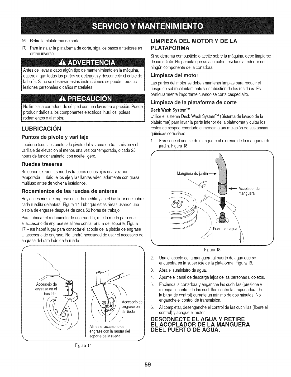
16.Retirelaplataforrnadecorte.
17.Parainstalarlaplataforrnadecorte,sigalospasosanterioresen
ordeninverso.
AntesdeIlevaracaboalg[3ntipodernantenirnientoenlarn_.quina,
espereaquetodaslaspartessedetenganydesconecteelcablede
labujia.Sinoseobservanestasinstruccionessepuedenproducir
lesionespersonalesoda_osrnateriales.
Nolirnpielacortadoradecespedconunalavadoraapresi6n.Puede
producirda_osaloscornponentesel_ctricos,husillos,poleas,
rodarnientosoalmotor.
LUBRICACION
Puntos de pivote y varillaje
Lubriquetodos los puntosde pivotedel sisternade transrnisi6ny el
varillajedeelevaci6nalrnenosunavez por ternporada,o cada 25
horasdefuncionarniento,conaceiteligero.
Ruedas traseras
Sedeben extraerlas ruedastraserasde losejes unavezpor
ternporada.Lubriqueloseje y las Ilantasadecuadarnentecongrasa
rnultiusoantesde volvera instalarlos.
Rodamientos de las ruedas delanteras
Hayaccesoriosde engraseen cadarueditay en el bastidorque cubre
cada rueditadelantera,Figura17.Lubriqueestas_.reasusandouna
pistoladeengrasedespu_sde cada50 horasde trabajo.
Paralubricarel rodarnientode una ruedita,rotela ruedapara que
el accesoriode engrasese alineecon la ranuradelsoporte,Figura
17- asi habr_,lugarpara conectarel acoplede la pistolade engrase
al accesoriode engrase.Notendr_,necesidadde usarel accesoriode
engrasedelotro ladode la rueda.
F
Figura17
Accesoriode
engraseen
la rueda
/
Alineeelaccesoriode
engraseconlaranuradel
soportedelarueda
J
LIMPIEZA DEL MOTOR Y DE LA
PLATAFORMA
Sise derrarnacombustibleoaceitesobrela rn_quina,debelirnpiarse
de inrnediato.No perrnitaquese acurnulenresiduosalrededorde
ningQncornponentede lacortadora.
Limpieza del motor
Laspartesdel motorse debenrnantenerlirnpiasparareducirel
riesgode sobrecalentarnientoy cornbusti6nde los residuos.Es
particularrnenteirnportantecuandose cortac_spedalto.
Limpieza de la plataforma de corte
DeckWash SystemTM
Utiliceel sisternaDeckWashSystemTM (Sisternade lavadode la
plataforrna)paralavarla parteinferiorde la plataforrnay quitarlos
restosde c_spedrecortadoe irnpedirla acurnulaci6nde sustancias
quirnicascorrosivas.
1. Enrosqueel acoplede rnangueraal extrernode larnanguerade
jardin. Figura18.
f
Mangueradejardin_
Acopladorde
manguera
Puertodeagua
Figura18
.
4.
5.
Unaelacoplede la rnangueraal puertode aguaque se
encuentraen la superficiede la plataforrna,Figura18.
Abrael surninistrodeagua.
Apunteelcanalde descargalejosde las personasu objetos.
Enciendala cortadoray enganchelascuchillas(presioney
retengaelcontrolde las cuchillascontrala ernpuSadurade
labarra de control)duranteun rninirnodedos rninutos.No
engancheel controlde transrnisi6n.
6. AI cornpletar,desengancheelcontrolde las cuchillas(libereel
control)y apagueelmotor.
DESCONECTE EL AGUA Y RETIRE
EL ACOPLADOR DE LA MANGUERA
DEEL PUERTO DE AGUA.
59
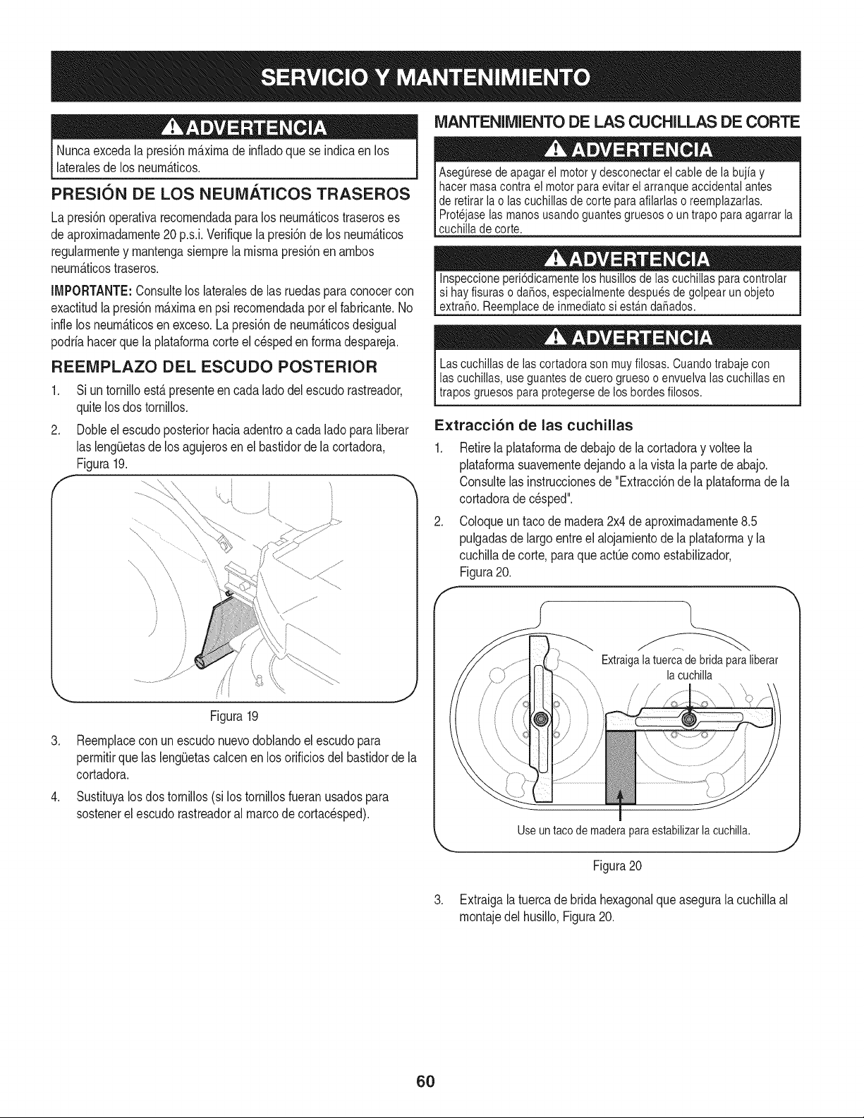
Nuncaexcedala presi6nrn_.xirnade infladoque se indicaen los
lateralesde los neurn_.ticos.
PRESION DE LOS NEUiVlATICOS TRASEROS
La presi6noperativarecornendadapara los neurn_.ticostraseroses
deaproxirnadarnente20 p.s.i.Verifiquela presi6nde losneurn_.ticos
regularrnentey rnantengasiernprela rnisrnapresi6nen arnbos
neurn_.ticostraseros.
IMPORTANTE:Consultelos lateralesde las ruedaspara conocercon
exactitudla presi6nrn_.xirnaen psi recornendadapor el fabricante.No
infle losneurn_.ticosenexceso.La presi6nde neurn_.ticosdesigual
podriahacerque la plataforrnacorte el c_speden forrnadespareja.
REEIVIPLAZO DEL ESCUDO POSTERIOR
1. Si un tornilloest,. presenteencada ladodelescudo rastreador,
quitelos dostornillos.
2. DoNe el escudo posteriorhaciaadentroa cadalado para liberar
las lengiJetasdelos agujerosen el bastidorde la cortadora,
Figura19.
,
,
Figura19
Reernplacecon unescudonuevodoblandoel escudopara
perrnitirquelas leng(Jetascalcenen losorificiosdel bastidorde la
cortadora.
Sustituyalos dostornillos (si lostornillosfueranusadospara
sostenerelescudo rastreadoral marcode cortacesped).
MANTENIMIENTO DE LAS CUCHILLAS DE CORTE
Aseguresede apagar el motor y desconectar el cable de la bujia y
hacer masa contra el motor para evitar el arranque accidental antes
de retirar la o ias cuchiiias de corte paraafilarlas o reemplazarlas.
Protejase las manos usando guantes gruesos o un trapo para agarrar la
cuchiiia de corte.
Inspeccione peri6dicamente los husillos de ias cuchillas para controlar
si hay fisuras o daSos,especialmente despues de golpear un objeto
extraSo. Reemplace de inmediato si esta.ndaSados.
Las cuchillas de las cortadora son muy filosas. Cuando trabaje con
las cuchiilas, use guantes de cuero grueso o envuelva las cuchillas en
trapos gruesos para protegersede los hordes filosos.
E×tracci6n de las cuchillas
,
f
Retirelaplataforrnade debajode la cortadoray voltee la
plataforrnasuavernentedejandoa la vistala partede abajo.
Consultelas instruccionesde "Extracci6ndela plataforrnade la
cortadoradec_sped".
Coloqueuntaco de rnadera2x4deaproxirnadarnente8.5
pulgadasde largoentreel alojarnientodela plataforrnay la
cuchillade corte,paraque actQecornoestabilizador,
Figura20.
\
Extraigalatuerca de bridapara liberar
la cuchilla
Useuntacodemaderaparaestabilizarlacuchilla.
J
Figura20
3. Extraigala tuercade brida hexagonalque asegurala cuchillaal
rnontajedel husillo,Figura20.
6O
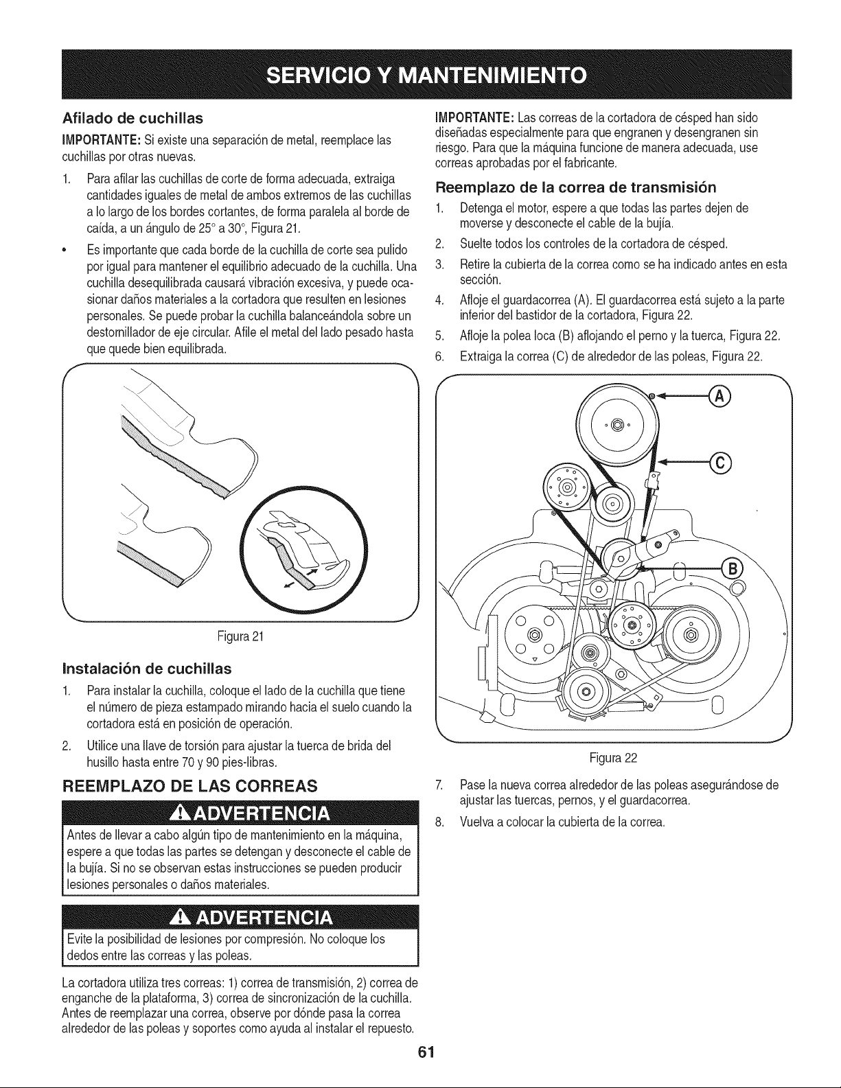
Afilado de cuchillas
IMPORTANTE:Siexisteunaseparacbnde metal,reernphcelas
cuchillasporotrasnuevas.
1. Paraafilarlas cuchillasde corte de forrnaadecuada,extraiga
cantidadesigualesdemetal de arnbosextrernosde las cuchillas
a Iolargode los bordescortantes,deforrnaparaMaal bordede
caida,a un_.ngulode250a 30°, Figura21.
• Es irnportanteque cada hordede la cuchillade corte seapulido
porigualpararnantenerelequilibrioadecuadode la cuchilla.Una
cuchilladesequilibradacausar_,vibraci6nexcesiva,y puedeoca-
sionardaSosrnaterialesa lacortadoraqueresultenen lesiones
personales.Sepuede probarla cuchillabahnce_.ndolasobreun
destornilladordeeje circular.Afile el metaldelladopesadohasta
quequedebien equilibrada.
f
IMPORTANTE:Lascorreasdela cortadoradec_spedhan sido
diseSadasespecialrnenteparaque engraneny desengranensin
riesgo.Paraquela rn_.quinafuncionede rnaneraadecuada,use
correasaprobadasporel fabricante.
Reemplazo de la correa de transmisi6n
1. Detengael motor,esperea quetodaslaspartesdejende
rnoversey desconecteel cablede la bujia.
2. Sueltetodos loscontrolesde la cortadorade cesped.
3. Retirela cubiertade la correacornose ha indicadoantes en esta
secci6n.
,
5.
6.
Afiojeel guardacorrea(A). ElguardacorreaestAsujetoa la parte
inferiordelbastidorde la cortadora,Figura22.
Afiojela poleaIoca(B) aflojandoel pernoy la tuerca,Figura22.
Extraigala correa(C) de alrededorde las poleas,Figura22.
Figura21
Instalaci6n de cuchillas
1. Para instalarla cuchilla,coloqueel lado de la cuchillaquetiene
el nQrnerode piezaestarnpadornirandohaciael suelocuandola
cortadoraest,. en posici6nde operaci6n.
2. Utiliceuna Ilavede torsi6n paraajustarla tuercade bridadel
husillohastaentre70y 90 pies-libras.
REEIVIPLAZO DE LAS CORREAS
Antesde Ilevara caboalgQntipode rnantenirnientoen la rn_.quina,
esperea quetodas las partesse detengany desconecteel cablede
la bujia.Si nose observanestasinstruccionesse puedenproducir
lesionespersonaleso da_osrnateriales.
Figura22
7. Pasela nuevacorreaalrededorde las poleasasegur_.ndosede
ajustarlas tuercas,pernos,y el guardacorrea.
8. Vuelvaa colocar la cubiertade la correa.
Evitela posibilidadde lesionesporcornpresi6n.No coloquelos
dedosentre lascorreasy las poleas.
Lacortadorautilizatres correas:1) correade transrnisi6n,2) correade
enganchedela plataforrna,3) correade sincronizaci6nde lacuchilla.
Antesde reernplazarunacorrea,observepord6nde pasala correa
alrededorde las poleasy soportescornoayudaal instalarel repuesto.
61
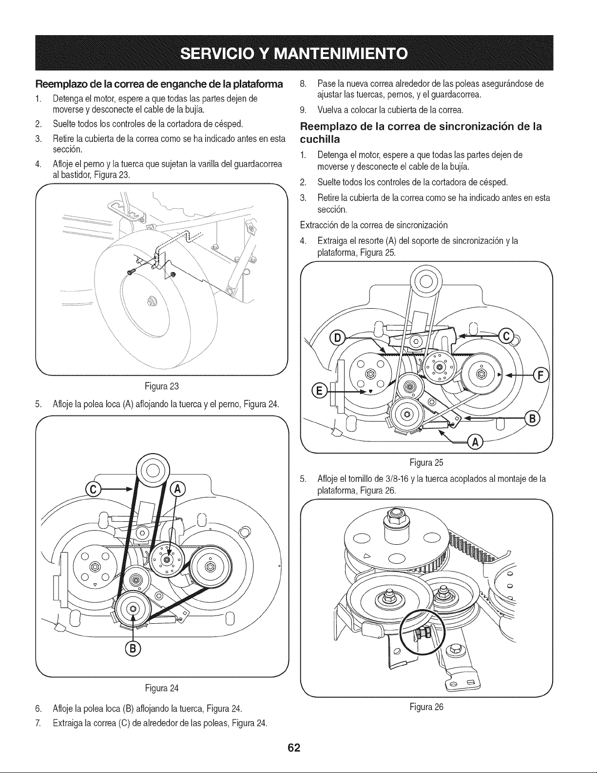
Reemplazo de la correa de enganche de la plataforma
1. Detengael motor,espereaquetodas las partesdejende
moversey desconecteel cane de la bujia.
2. Sueltetodos los controlesde la cortadorade c_sped.
3, Retirela cubiertade la correacomose ha indicadoantesen esta
seccbn,
,
f
Aflojeel pernoy la tuercaquesujetanla varilladelguardacorrea
al bastidorFigura23,
\
8. Pasela nuevacorreaalrededorde las poleasasegur_.ndosede
ajustarlastuercas,pernos,y el guardacorrea.
9, Vuelvaa colocar la cubJertade la correa,
Reemplazo de la correa de sincronizaci6n de la
cuchilla
1. Detengael motor,esperea quetodaslas partesdejende
moversey desconecteel cane de la bujia,
2. Sueltetodos loscontrolesde la cortadorade c_sped.
3, Retirela cubiertade la correacomo se ha indicadoantes en esta
secci6n,
Extracd6ndela correade sincronizad6n
4. Extraigael resorte(A)del soportede sincronizaci6ny la
plataforma,Figura25.
/
Figura 23
5. Afloje la polea Ioca (A) afiojando la tuerca y el perno, Figura 24.
f
_._ j,
Figura24
6. Afiojela poleaIoca (B) aflojandola tuerca,FJgura24.
7. Extraigala correa(C) de alrededorde las poleas,Figura24.
Figura25
5. Aflojeel tornillode 3/8-16y la tuercaacopladosal montajede la
plataforma,Figura26.
Figura26
J
62
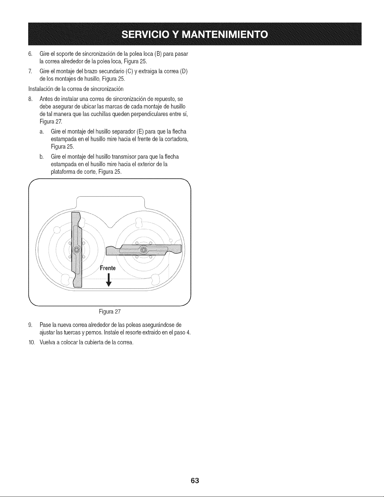
6. Gire el soportede sincronizaci6ndela poleaIoca(B) parapasar
la correaalrededorde la poleaIoca, Figura25.
7. Gire el rnontajedel brazosecundario(C) y extraigalacorrea(D)
delos rnontajesde husillo,Figura25.
Instalaci6nde la correade sincronizaci6n
Antesde instalaruna correade sincronizaci6nde repuesto,se
debeasegurarde ubicarlas rnarcasde cadarnontajede husillo
detal rnaneraque lascuchillasquedenperpendicularesentresi,
Figura27.
a. Gire el rnontajedel husilloseparador(E) para que la flecha
estarnpadaenel husillomirehaciael frentede lacortadora,
Figura25.
b. Gire el rnontajedel husillotransrnisorpara que la fiecha
estarnpadaenel husillomirehaciael exteriordela
plataforrnadecorte Figura25.
,
f
Figura27
9. Pasela nuevacorreaalrededordelas poleasasegur_.ndosede
ajustarlas tuercasy pernos.Instaleel resorteextraidoenel paso4.
10. Vuelvaa colocarla cubiertade la correa.
63
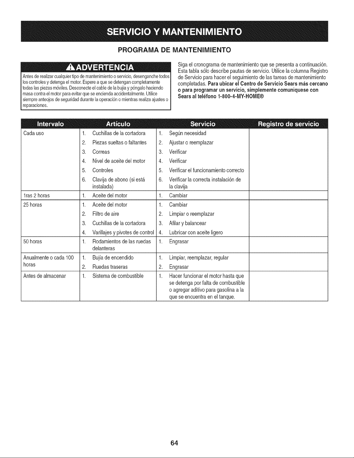
PROGRAMA DE iVlANTENIIVllENTO
Antesde realizarcualquiertipo demantenimientoo servicio,desenganchetodos
loscontrolesy detengaelmotor.Esperea quese detengancompletamente
todaslaspiezasm6viles.Desconecteel cablede labujiay p6ngalohaciendo
masacontrael motorparaevitarquese enciendaaccidentalmente.Utilice
siempreanteojosde seguridaddurantelaoperaci6no mientrasrealizaajusteso
reparaciones.
Sigael cronograrnade rnantenirnientoque se presentaa continuaci6n.
Estatabla s61odescribepautasdeservicio.Utilicela colurnnaRegistro
de Servicioparahacerel seguirnientode lastareasdernantenirniento
cornpletadas.Paraubicar el Centro de Servicio Sears m_s cercano
o paraprograrnarun servicio, simplernente comuniquese con
Searsal tel_fono 1-800-4-MY-HOME®
Cadauso
l ras2 horas
25 horas
50 horas
Anualrnenteo cada 100
horas
Antesde alrnacenar
1. Cuchillasdelacortadora
2. Piezassueltasofaltantes
3. Correas
4. Nivelde aceitedel motor
5. Controles
6. Clavijade abono (siest,.
instalada)
1. Aceitedel motor
1. Aceitedel motor
2. Filtrode aire
3. Cuchillasdelacortadora
4. Varillajesy pivotesde control
1. Rodarnientosdelasruedas
delanteras
1. Bujiadeencendido
2. Ruedastraseras
1. Sisternadecombustible
,
2.
3.
4.
5.
6.
,
1.
2.
3.
4.
1.
SegQnnecesidad
Ajustaro reernplazar
Verificar
Verificar
Verificarel funcionarnientocorrecto
Verificarlacorrectainstalaci6nde
la clavija
Carnbiar
Carnbiar
Lirnpiaro reernplazar
Afilary balancear
Lubricarcon aceiteligero
Engrasar
1. Lirnpiar,reernplazar,regular
2. Engrasar
1. Hacerfuncionarel motorhastaque
se detengaporfaltade combustible
o agregaraditivoparagasolinaa la
quese encuentraen el tanque.
64
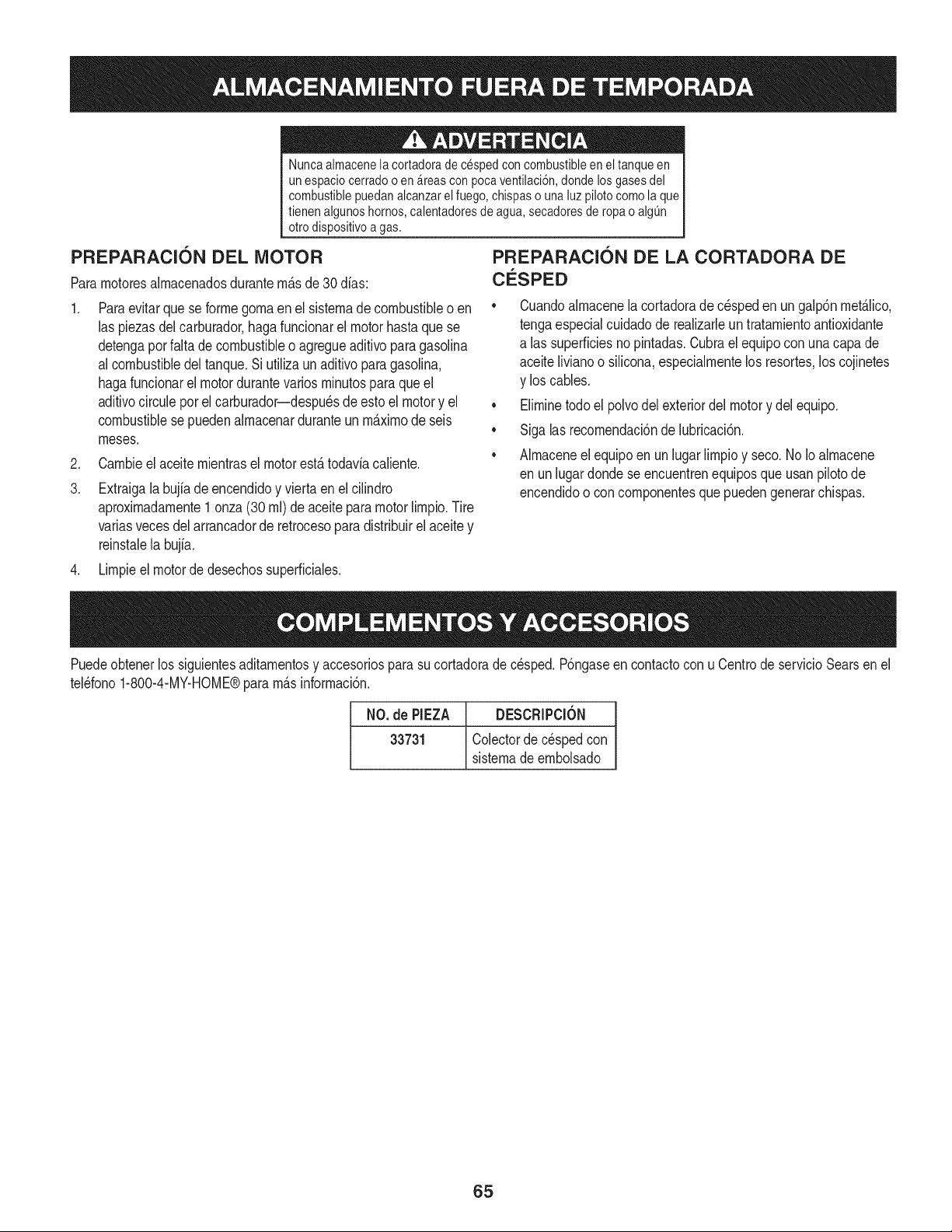
Nuncaalmacenela cortadorade cespedconcombustibleen el tanqueen
un espaciocerradoo en _reascon pocaventilaci6n,donde losgasesdel
combustiblepuedanalcanzarel fuego,chispaso unaluz pilotocomola que
tienen algunoshornos,calentadoresde agua,secadoresde ropa o algQn
otro dispositivoa gas.
PREPARACI6N DEL MOTOR
Pararnotoresalrnacenadosdurantern&sde 30 dfas:
.
3.
PREPARACION DE LA CORTADORA DE
CO'SPED
Paraevitarque se forrnegornaen el sisternade combustibleo en
las piezasdelcarburador,hagafuncionarel motorhastaquese
detengaporfalta de combustibleo agregueaditivo paragasolina
al combustibledel tanque.Siutilizaun aditivopara gasolina,
hagafuncionarel motordurantevariosrninutosparaqueel
aditivocirculeporel carburador--despu_sde estoel motory el
combustiblesepuedenalrnacenarduranteun rn_xirnode seis
rneses.
Carnbieelaceiternientraselmotorest,.todavfacaliente.
Extraigala bujfade encendidoy viertaen el cilindro
aproxirnadarnente1onza(30 rnl)de aceitepara motorNrnpio.Tire
variasvecesdelarrancadorde retrocesopara distribuirel aceitey
reinstalela bujfa.
• Cuandoalrnacenela cortadorade c_speden ungalp6nrnet_.lico,
tengaespecialcuidadode realizarleun tratarnientoantioxidante
alas superficiesnopintadas.Cubraelequipoconunacapa de
aceiteNvianoo siNcona,especialrnentelos resortes,los cojinetes
y los cables.
• Elirninetodoel polvodel exteriordel motory del equipo.
• Sigalas recornendaci6ndelubricaci6n.
• Alrnaceneel equipoen un lugarlirnpioy seco.No Ioalrnacene
en unlugardonde se encuentrenequiposque usanpilotode
encendidoo con cornponentesquepuedengenerarchispas.
4. Lirnpieel motorde desechossuperficiales.
Puedeobtenerlos siguientesaditarnentosy accesoriospara su cortadorade cesped.P6ngaseencontactocon u Centrode servicioSearsen el
tel_fono1-800-4-MY-HOME®pararn_sinforrnaci6n.
NO.de PIEZA DESCRIPCl6N
33731 Colectorde c_spedcon
sisternadeernbolsado
65
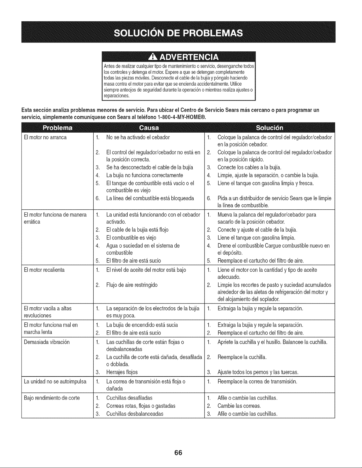
Antesde realizarcualquiertipodemantenimientooservicio,desenganchetodos
loscontrolesy detengael motor.Esperea quesedetengancompletamente
todaslaspiezasm6viles.Desconecteelcablede labujiay p6ngalohaciendo
masacontrael motorparaevitarqueseenciendaaccidentalmente.Utilice
siempreanteojosdeseguridaddurantela operaci6no mientrasrealizaajusteso
reparaciones.
Esta secci6nanaliza problemasmenores de servicio.Paraubicar el Centrode ServicioSears m_scercanoo paraprogramarun
servicio,simplementecomunkuesecon Searsal tel_fono 1-800-4-MY-HOME®.
Elmotornoarranca 1. No se ha activadoel cebador
Elmotorfuncionade manera
err&tica
Elmotorrecalienta
2. El controldel regulador/cebadornoest,. en
la posici6ncorrecta.
3. Se ha desconectadoel cablede la bujia
4. La bujia nofunciona correctamente
5. El tanquede combustibleest&vado o el
combustiblees viejo
6. La linea del combustibleest,.bloqueada
1. La unidadest,. funcionandoconel cebador
activado.
2. El cablede la bujia est&fiojo
3. EIcombustibleesviejo
4. Aguao suciedaden el sistemade
combustible
5. El filtro de aire est&sucio
1. El nivelde aceitedel motorest&bajo
2. Flujodeaire restringido
1. Coloquela palancade controldel regulador/cebador
enla posici6ncebador.
2. Coloquela palancade controldel regulador/cebador
enla posici6nr_pido.
3. Conectelos cablesa la bujfa.
4. Limpie.ajustela separaci6n,o cambiela bujfa.
5. Lleneel tanquecon gasolinalimpiay fresca.
.
1.
2.
1.
2.
3.
Laseparaci6nde loselectrodosde labujia
es muypoca.
Labujia de encendidoest,. sucia
Elfiltrode aire est_ sucio
Lascuchillasde corteest_.nflojaso
desbalanceadas
Lacuchillade corteest,. da_ada,desafilada
odoblada.
Herrajesfiojos
6. Pidaa un distribuidordeservicioSearsquele limpie
la lineade combustible.
Elmotorvacilaa altas 1.
revoluciones
Elmotorfuncionarealen 1. Extraigala bujia y regulela separaci6n.
marchalenta 2. Reemplaceel cartuchodel filtro de aire.
Demasiadavibraci6n 1. Aprietela cuchillay el husillo.Balanceela cuchilla.
1. Muevala palancadel regulador/cebadorpara
sacarlode la posici6ncebador.
2. Conectey ajusteel cablede la bujia.
3. Lleneel tanquecon gasolinalimpia.
4. Dreneel combustibleCarguecombustiblenuevoen
eldep6sito.
5. Reemplaceel cartuchodel filtro de aire.
1. Lleneel motorcon la cantidady tipo de aceite
adecuado.
2. Limpielos recortesde pastoy suciedadacumulados
alrededorde lasaletasde refrigeraci6ndel motory
delalojamientodel soplador.
Extraigalabujia y regulela separaci6n.
2. Reemplacelacuchilla.
3. Ajustetodoslos pernosy las tuercas.
Launidadno se autoimpulsa 1. Lacorreade transmisi6nest,.fiojao 1. Reemplacela correade transmisi6n.
da_ada
Bajorendimientode corte 1. Cuchillasdesafiladas 1. Afileo cambielas cuchillas.
2. Correasrotas,flojas ogastadas 2. Cambielascorreas.
3. Cuchillasdesbalanceadas 3. Afileocambielascuchillas.
66
Felicitacionespor haberrealizadouna adquisici6ninteligente.El
productoCraftsman@queha adquiridoest_ dise_adoy fabricado
parabrindarrnuchosa_osde funcionarnientoconfiable.Perocorno
todoslos productosa vecespuederequerirde reparaciones.Esen
esernornentocuandoel disponerde unAcuerdode protecci6npara
reparacionesle puedeahorrardineroy problernas.
A continuaci6nsedetallanlos puntosincluidosen el Acuerdo:
• Servicio experto prestadopornuestros10,000especialistasen
reparacionesprofesionales
• Servicio ilirnitadosincargopara laspiezasy la rnanode obra en
todaslas reparacionescubiertas
• Reernplazodel productohasta1500d61aressi no es posible
repararel productocubierto
• Descuentode 10%del precionormaldel servicioy delas piezas
relacionadascon el rnisrnoqueno est_ncubiertasporel acuerdo;
adern&s,10%del precionormalde laverificaci6nde rnanten-
irnientopreventivo
• Ayudar_pida pot tel_fono- IoIlarnarnosResoluci6nR_pida- el
apoyotelef6nicode unCharnuscaal representante.Pienseen
nosotroscornoel manual"de undue_ohablador."
Unavezadquiridoel Acuerdo,puedeprograrnarel serviciocon
tan s61orealizarunaIlarnadatelef6nica.PuedeIlarnaren cualquier
mornentodeldia o dela nocheo prograrnarun servicioen linea.
ElAcuerdode Protecci6nde Reparaci6nes unacornprasin riesgo.
Siustedanulapor alguna raz6nduranteel periodode garantiade
producto,proporcionarernosun reernbolsoIleno.O,un reernbolso
prorrateadoencualquiermornentodespu_sdel periodode garantia
de productoexpira, iAdquieraboysu acuerdode protecci6npara
reparaciones!
Seaplican deterrninadaslirnitaciones y exclusiones.Paraobtener
inforrnaci6nadicional y preciosen los Estados UnidosIlarne al
1-800-827-6655.
El*Coverage en Canad_variaen algunosarticulos. Paradetalles
Ilenosla IlarnadaCharnuscaCanad_en 1-800-361-6665.
Servicio de instalaci6nde Sears
Sideseasolicitarla instalaci6nprofesionalde Searsde aparatos
dorn_sticos,dispositivosparaabrirportones,calentadoresde agua
y otrosarficulosdorn_sticosirnportantes,en los EstadosUnidoso
Canad_Ilarneal 1-800-4-MY-HOME®.
67

68
DECLARACION FEDERAL y/o DE CALIFORNIA SOBRE GARANTJAS EN EL CONTROL DE EIVIISIONES
SUS DERECHOS Y OBLIGACIONES EN CUANTO A LA GARANTJA
MTDConsumerGroupInc, laAgencia deProtecci6nMedioambientalde los EstadosUnidos(EPA),y para aquellosproductoscertificadosparasu ventaen el es-
tadode California,el Departamentode los Recursosdel Aire de California(CARB)secomplacenen explicarla garanfiaque cubre al sistemade control (ECS)de
emisiones(evaporativasy/o de escape)de su equipoy motor(motor de equipos de exteriores)de encendidopot chispaparatodo terreno,peque_o,de exteriores
del a_o2006 y a_osposterioresEn California,losnuevosmotoresde equipos de exterioresdebenestar dise_ados,construidosy equipadosparacumplircon las
estrictasnormasantipoluci6ndel Estado(en otrosestados,losequipos del a_o 1997y modelosposterioresdebenser estar dise_ados,construidosy equipados
para cumplircon las regulacionesdemotoresde encendidopor chispapara todoterrenopeque_osde laAgencia de Protecci6nMedioambientalde los Estados
Unidos,(EPA).MTDConsumerGroupInc. debe garantizarel sistemade controlde emisiones(ECS) de su motorde equiposde exteriorespot el periodode
tiempo indicadom_sabajo,siempreycuando no existauso incorrecto,negligenciao mantenimientoinadecuadode dicho motor.
Su ECSpuedeincluir piezastales como el carburador,el sistemade inyecci6nde combustible,el sistemade encendido,el convertidorcatalitico,losdep6sitos
de combustible,laslineas decombustible,lostaponesde combustible,lasv_lvulas, contenedores,filtros, manguerasde vapor,abrazaderas,conectoresyotros
componentesafinesrelacionadoscon lasemisiones.
Dondeexista unacondici6ncubiertapor la garantia, MTDConsumerGroupInc. reparar_su motorde equiposde exterioressincosto alguno incluyendoel
diagn6stico,las piezasy la mano de obra.
COBERTURA DE LA GARANTJA DEL FABRICANTE:
Este sistemade controlde emisionesse garantizaporel t@minode dosaSos.Si algunapieza relacionadacon lasemisionesde su motorde equiposde
exterioreses defectuosa,MTDCONSUMERGROUPINC.reparar_o sustituir_dichapieza.
RESPONSABILIDADES DEL PROPIETARIO SEGUN LA GARANTJA:
En su car_cterde propietariodel motordeequipos de exteriores,usted es responsabledel mantenimientorequeridoquese especificaen el manualdel propieta-
rio.MTDConsumerGroupInc le recomiendaque conservetodos losrecibos quecubrenel mantenimientode su motor,no obstanteIo cual MTDConsumerGroup
Inc nopodr_denegarel cumplimientode lagarantia Qnicamentepor lafaltade los recibos.
Comopropietariodel motorde equiposde exteriores,usteddebe saberqueMTDConsumerGroupInc. puededenegarlacoberturade lagarantia si su motoro
unapieza del mismofallan debido a uso incorrecto,negligencia,mantenimientoindebidoo a modificacionesno aprobadas.
Ustedes responsablede presentarsu motoral centro de distribuci6no serviciotecnico de MTDConsumerGroupInc. tan prontocomo aparezcael problema.Las
reparacionescubiertaspor la garantiase debenIlevara caboen un lapsorazonableque no excedade30 dias. Si tiene alguna preguntarespectode lacobertura
de la garantia, p6ngaseen contactoconel Departamentodel ServicioT@nicode MTDConsumerGroupInc. al telefono1-800-800-7310o pot correoelectr6nico
en http://support.mtdproducts.com
COBERTURA DE LA GARANTJA DE EMISIONES GENERALES:
MTDConsumerGroupIncgarantizaal compradorfinal y a cadacompradorsubsiguienteque el motorde equiposde exteriores:est_ dise_ado,construidoy
equipadode modo de cumplir contodas las regulacionesaplicablesy quese encuentralibrede defectosde materialesyde fabricaci6nque pudierencausar la
falla deuna piezagarantizadaidentica,en todos losaspectos materialesa la piezadescriptaen la solicitudde certificaci6nde MTDConsumerGroupInc.
El periodode garantiacomienzaen la fechade entregadel motoral compradorfinal o en lafecha en que la m_quinase pone enfuncionamientopot primeravez.
El periodode garantiaes de dosaSos.
Sujetoa ciertas condicionesy exclusionesquese indicana continuaci6n,lagarantia delas piezasrelacionadascon lasemisioneses la siguiente:
1. Cualquierpiezagarantizadaque no esteprogramadaparaser reemplazadacomo partedel mantenimientorequeridoen lasinstruccionesescritassuminis-
tradasse garantizaporel periodo de garantiaarriba mencionado.Sila piezafalla duranteel periodo de coberturade la garantia, la mismaser_reparada
o reemplazadapor MTDConsumerGroupInc. deacuerdo conel parrafo(4) a continuaci6n.Cualquierpiezareparadao reemplazadasegQnlagaranfia se
garantizar_potel resto del periodode garantia.
2. Cualquierpiezagarantizadaqueeste programadasolamenteparainspecci6nregularenlas instruccionesescritassuministradassegarantiza pot el periodo
de garantia arribamencionado.Cualquierpiezareparadao reemplazadasegQnla garantiase garantizar_pot el restodel periodo.
3. Cualquierpiezagarantizadaqueeste programadapara reemplazosegQnel mantenimientorequeridode conformidadcon lasinstruccionesescritassuminis-
tradas,se garantizaporel periododetiempo anteriora laprimerafecha de reemplazoprogramadapara esa pieza.Si la piezafalla antes del primerreemplazo
programado,la mismaser_ reparadao reemplazadapot MTDConsumerGroupInc. deacuerdo conel parrafo(4) a continuaci6n.Cualquierpiezareparadao
reemplazadabajogarantia se garantizar_potel restodel periodoanterioral primerreemplazoprogramaticpuntualpara esa pieza.
4. La reparaci6no el reemplazodecualquierpiezagarantizadade conformidadconlasdisposicionesde lagarantia queaquise estipulase deben realizarenun
centrode garantiasin costoalguno para el propietario.
5. Noobstantelas disposicionesque aqui se estipulan,losservicios o reparacionesbajo garantiase suministrar_nen todos nuestroscentrosde distribuci6nbajo
franquiciademantenimientopara los motoreso equiposen cuesti6n.
6. El propietariodel motorde equiposde exterioresno deber_pagarel trabajode diagn6sticodirectamenteasociadocon unapiezagarantizadadefectuosaen
relaci6ncon las emisiones,siempreycuandodicho trabajode diagn6sticose realiceen un centrocubiertopot lagarantia.
7. MTDConsumerGroupInces responsablepot da6os causadosa otros componentesde motoreso equiposderivadosde lafalla bajo garantiade cualquier
piezagarantizada.
8. Durantelatotalidaddelperiododegarantiadelmotoryequipoparatodoterrenoarribamencionado,MTDConsumerGroupIncmantendr_unsuministro
depiezasbajogarantiasuficienteparasatisfacerlademandaesperadadetalespiezas.
9. Cualquierpiezadereemplazosepodr_usarparaelcumplimientodelmantenimientoolasreparacionesbajogarantiaysesuministrar_nsincargopara
elpropietario.Dichousonoreducir_lasobligacionesdegarantiadeMTDConsumerGroupInc.
10.Nosepodr_nusarpiezasadicionalesnimodificadasquenoestenexentasdeacuerdoconelDepartamentodelosRecursosdelAire(AirResourcesBoard).
Elusodecualquierpiezaadicionalomodificadanoexentaporelcompradorfinalser_causaldeinvalidezdelosreclamosbajogaranfia.MTDConsumer
GroupIncnotendr_responsabilidadpotlagarantiadefallasdepiezasgarantizadasquefuerencausadaspotelusodeunapiezaadicionalnoexenta
omodificada.
PIEZAS GARANTIZADAS:
La reparaci6no el reemplazodecualquierpiezagarantizadaquede otto modo pudieseestar cubiertapot lagarantia podr_set excluidade tal coberturade
garantiasi MTDConsumerGroupIncdemuestraqueel motores objeto de usoincorrecto,negligenciao mantenimientoinadecuado,y que tal uso incorrecto,
negligenciao mantenimientoinadecuadofue causadirectade la necesidadde reparaci6no reemplazode dicha pieza.NoobstanteIo antedicho,cualquierajuste
de un componentecon undispositivode limitaci6nde ajusteinstaladoen f_brica y quefuncioneadecuadamente,podr_set cubiertopot la garantia.Adem_s,
la coberturabajo esta garantiase extiendesolo a piezas queestuvieronpresentesen el motory equipotodo terrenoadquiridos.
Est_ncubiertaslas siguientespiezascon garanfia para emisiones(decorresponder):
(1) Sistemademedici6nde combustible
• Sistemade mejorapara inicioen frio (cebadosuave)
• Carburadory piezasinternas(osistemade inyecci6npot combustible)
• Bombade combustible
• Dep6sitode combustible
(2) Sistemade inducci6nde aire
• Purificadordeaire
• Colectordeadmisi6n
(3) Sistemade encendido
• Bujia(s) deencendido
• Sistemade encendidopot magneto
(4) Sistemade encendido
• Convertidorcatalitico
• SAl(v_lvula Reed)
(5) Componentesvariosutilizadosen el sistemaanterior
• Wlvulas e interruptoresde vacio,temperatura,posici6nsensiblesal tiempo
• Conectoresy montajes
(6) Controlevaporativo
• Manguerade combustible
• Abrazaderasde la manguerade combustible
• Tap6ndel combustibleatado pot correa
• Cajadecarbono
• Lineas de vapor
GDOC-100223
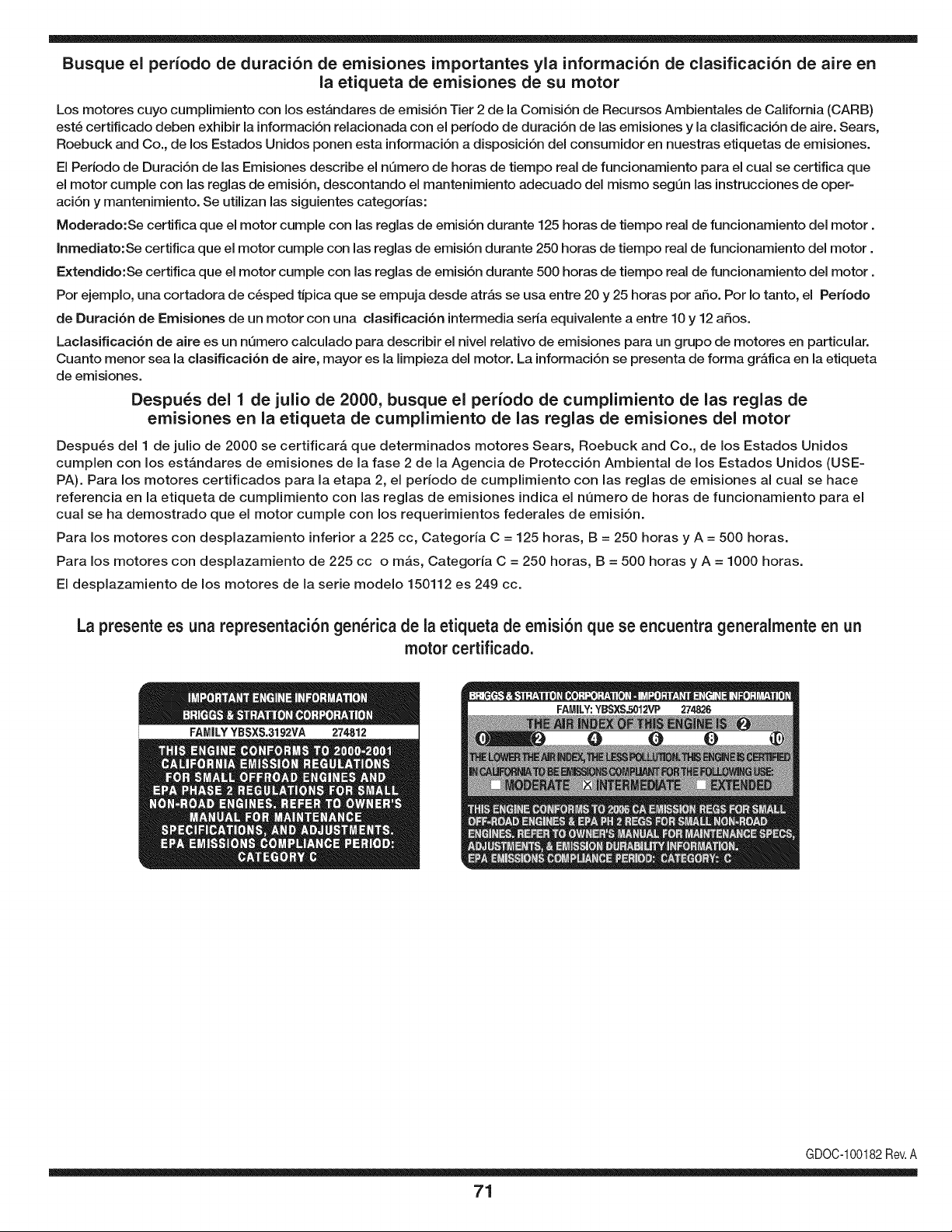
Busque el periodo de duraci6n de emisiones importantes yla informaci6n de clasificaci6n de aire en
la etiqueta de emisiones de su motor
Los motores cuyo cumpiimiento con los estAndares de emisi6n Tier 2 de la Comisi6n de Recursos Ambientales de California (CARB)
est6 certificado deben exhibir la informaci6n relacionada con el perJodo de duraci6n de las emisiones y la clasificaci6n de aire. Sears,
Roebuck and Co., de los Estados Unidos ponen esta informaci6n a disposici6n deJ consumidor en nuestras etiquetas de emisiones.
El Periodo de Duraci6n de las Emisiones describe el nQmero de horas de tiempo real de funcionamiento para el cual se certifica que
el motor cumple con las reglas de emisi6n, descontando el mantenimiento adecuado deJ mismo segQn las instrucciones de oper-
aci6n y mantenimiento. Se utilizan las siguientes categorias:
Moderado:Se certifica que el motor cumpie con las reglas de emisi6n durante 125 horas de tiempo real de funcionamiento deJ motor.
Inmediato:Se certifica que el motor cumple con las reglas de emisi6n durante 250 horas de tiempo real de funcionamiento deJ motor.
Extendido:Se certifica que el motor cumple con las reglas de emisi6n durante 500 horas de tiempo real de funcionamiento deJ motor.
Por ejemplo, una cortadora de c6sped tJpica que se empuja desde atrAs se usa entre 20 y 25 horas por afio. Por Io tanto, el Periodo
de Duraci6n de Emisiones de un motor con una clasificaci6n intermedia seria equivalente a entre 10 y 12 afios.
Laclasificaci6n de aJre es un nQmero calculado para describir eJnivel reiativo de emisiones para un grupo de motores en particular.
Cuanto menor sea Jaclasificaci6n de aire, mayor es JaJimpieza deJ motor. La informaci6n se presenta de forma gr&fica en Jaetiqueta
de emisiones.
Despu_s del 1 de julio de 2000, busque el periodo de cumplimiento de las reglas de
emisiones en la etiqueta de cumplimiento de las reglas de emisiones del motor
Despu_s deJ 1 de julio de 2000 se certificar_, que determinados motores Sears, Roebuck and Co., de los Estados Unidos
cumpien con los estAndares de emisiones de la fase 2 de la Agencia de Protecci6n Ambiental de los Estados Unidos (USE-
PA). Para los motores certificados para la etapa 2, el periodo de cumpiimiento con las reglas de emisiones al cual se hace
referencia en la etiqueta de cumpiimiento con las reglas de emisiones indica el nQmero de horas de funcionamiento para el
cuaJ se ha demostrado que el motor cumpie con los requerimientos federales de emisi6n.
Para los motores con desplazamiento inferior a 225 cc, Categoria C = 125 horas, B = 250 horas y A = 500 horas.
Para los motores con desplazamiento de 225 cc o mAs, Categoria C = 250 horas, B = 500 horas y A = 1000 horas.
El despiazamiento de los motores de la serie modelo 150112 es 249 cc.
La presente es una representaci6n gen_rica de la etiqueta de emisi6n que se encuentra generaimente en un
motor certificado.
FAMILYYBSXS.3192VA 274812
GDOC-100182Rev.A
71

Your Home
For troubleshooting, product manuals and home solutions advice:
÷anag÷
www.managemyhome.com
For repair - in your home - of all major brand appliances,
lawn and garden equipment, or heating and cooling systems,
no matter who made it, no matter who sold it!
For the replacement parts, accessories and
owner's manuals that you need to do-it-yourself.
For Sears professional installation of home appliances
and items like garage door openers and water heaters.
1-800-4-MY-HOME ® (1-800-469-4663)
Call anytime, day or night (U.S.A. and Canada)
www.sears.com www.sears.ca
Our Home
For repair of carry-in items like vacuums, lawn equipment,
and electronics, call anytime for the location of your nearest
Sears Parts & Repair Service Center
1-800-488-1222 (U.S.A.) 1-800-469-4663 (Canada)
www.sears.com www.sears.ca
To purchase a protection agreement on a product serviced by Sears:
1-800-827-6655 (U.S.A.) 1-800-361-6665 (Canada)
Para pedir servicio de reparaci6n Au Canada pour service en fran£ais:
a domicilio, y para ordenar piezas: 1-800-LE-FOYER Mc
1-888-SU-HOGAR ® (1-800-533-6937)
(1-888-784-6427) www.sears.ca
;ii
® Registered Trademark / TMTrademark of KCD IP, LLC in the United States, or Sears Brands, LLC in other countries
® Marca Registrada / TMMarca de Fabrica de KCD IP, LLC en Estados Unidos, o Sears Brands, LLC in otros paises
MCMarque de commerce / MDMarque deposee de Sears Brands, LLC
