Operator's Manual
CRRFr MRN
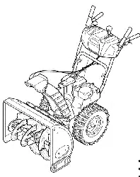
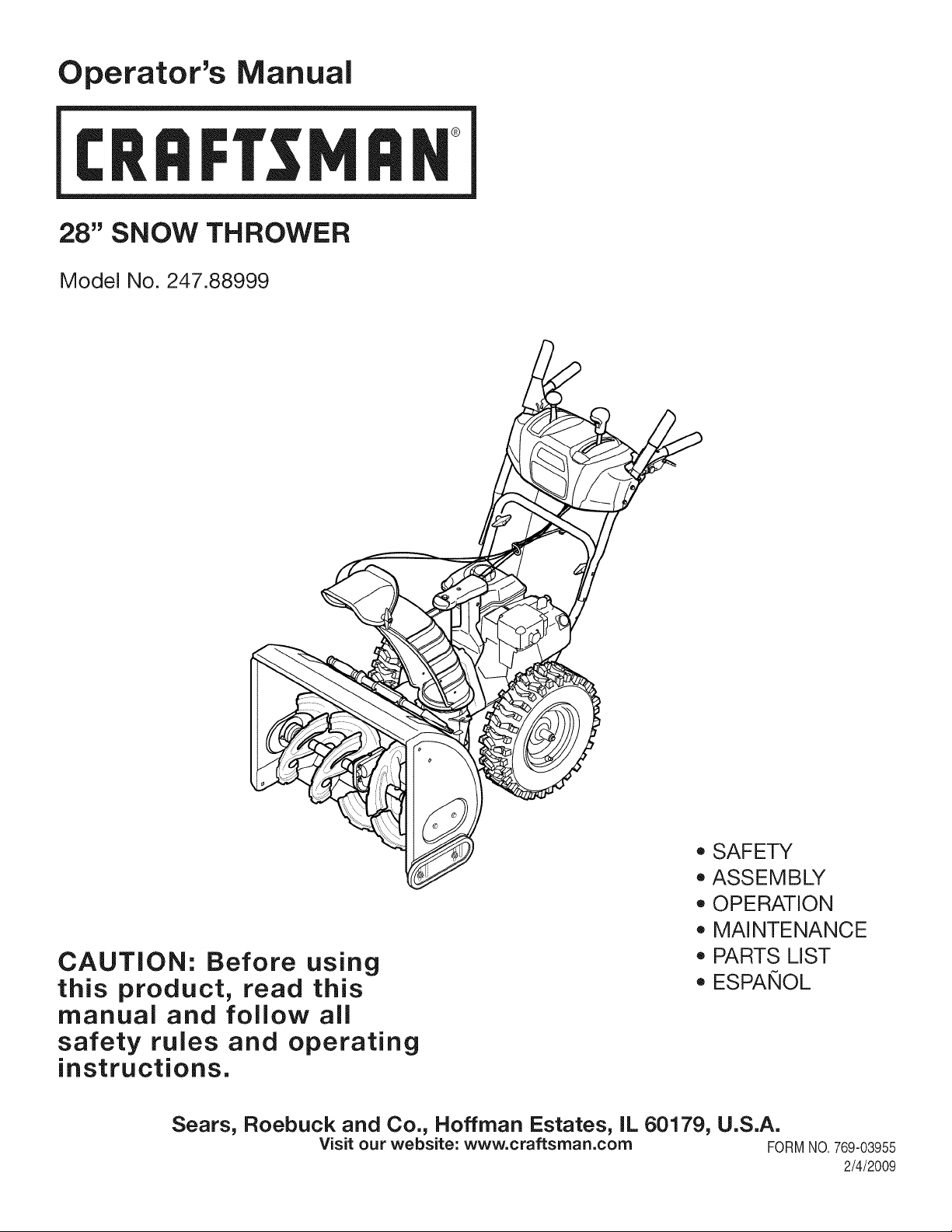
28" SNOW THROWER
Model No. 247.88999
CAUTION: Before using
this product, read this
manual and follow all
safety rules and operating
instructions.
o SAFETY
ASSEMBLY
OPERATION
MAINTENANCE
PARTS LIST
o ESPArqOL
Sears, Roebuck and Co., Hoffman Estates, IL 60179, U.S.A.
Visit our website: www.craftsman.com FORMNO.769-03955
2/4/2009
WarrantyStatement.................... Page2
SafeOperationPractices.............. Pages3-6
SafetyLabels......................... Page7
Assembly......................... Pages8-11
Operation........................ Pages12-15
Service&Maintenance.............. Pages16-21
Off-SeasonStorage................... Page22
Troubleshooting...................... Page23
PartsList......................... Pages24-36
RepairProtectionAgreement............ Page40
Espa_ol............................. Page41
ServiceNumbers................... BackPage
CRAFTSMAN LiMiTED WARRANTY
Two Years on Snow Thrower
Whenoperatedandmaintainedaccordingto all suppliedinstructions,if thissnowthrowerfails dueto a defectin materialor workmanshipwithin
two yearsfromthedate or purchase,call 1-800-4-MY-HOME®to arrangefor free repair.
Thiswarrantyappliesfor only90days fromthe dateof purchaseif this snowthroweris everusedfor commercialor rentalpurposes.
Duringthe firstyearof purchase,therewill be no chargefor warrantyservicein yourhome.Foryourconvenience,in-homewarrantyservicewill
still beavailableafterthe first yearof purchase,buta trip chargewillapply.Thischargewill bewaivedif you transportthe snowthrowerto an
authorizedCraftsmandrop-off location.Forthe nearestauthorizedlocation,call 1-800-4-MY-HOME®.
Thiswarranty coversONLYdefects inmaterial and workmanship. Sears will NOTpay for:
• Expendableitemsthat becomewornduring normaluse,includingbut not limitedto skid shoes,shaveplate,shearpins,sparkplug,air
cleaner,belts,andoil filter.
• Standardmaintenanceservicing,oil changes,ortune-ups.
• Tire replacementor repaircaused by puncturesfromoutsideobjects,suchas nails,thorns,stumps,orglass.
• Tire orwheel replacementor repairresultingfromnormalwear,accident,or improperoperationor maintenance.
• Repairsnecessarybecauseof operatorabuse,includingbut not limitedto damagecausedby impactingobjectsthatbend theframeor
crankshaft,or over-speedingthe engine.
• Repairsnecessarybecauseof operatornegligence,includingbut notlimitedto,electricalandmechanicaldamagecausedby improper
storage,failureto use the propergradeandamountof engineoil, or failureto maintaintheequipmentaccordingto the instructionscontained
inthe operator'smanual.
• Engine(fuel system)cleaningor repairscausedby fuel determinedto be contaminatedor oxidized(stale). Ingeneral,fuelshouldbe used
within30 daysof itspurchasedate.
• Normaldeteriorationand wear of theexteriorfinishes,or productlabel replacement.
Thiswarrantyappliesonlywhilethis productisusedinthe UnitedStates.
Thiswarrantygivesyou specificlegalrights,and youmayalsohaveother rightswhichvaryfromstateto state.
Sears,Roebuck and Co., NoffmanEstates, IL 60179
EngineOilType: SAE5W-30
EngineOilCapacity: 20ounces
FuelCapacity: 3 Quarts
SparkPlug: Champion®RC12YC
SparkPlugGap: .030"
Model Number.................................................................
Serial Number.................................................................
Dateof Purchase.............................................................
Recordthe modelnumber,serialnumber
anddateof purchaseabove
© SearsBrands,LLC
2
Thissymbolpointsout importantsafetyinstructionswhich,if not
followed,couldendangerthepersonalsafetyand/orpropertyof
yourselfandothers. Readand followall instructionsin this manual
beforeattemptingto operatethis machine.Failureto complywith
theseinstructionsmayresultin personalinjury.Whenyou seethis
symbol,HEEDITSWARNING!
CALIFORNIA PROPOSiTiON 65
EngineExhaust,someof itsconstituents,andcertainvehicle
componentscontainoremit chemicalsknownto Stateof California
to causecancerand birthdefectsorotherreproductiveharm,
Thismachinewas builtto beoperatedaccordingto the safe opera-
tion practicesin thismanual.As with any type of powerequipment,
carelessnessor error onthe partof the operatorcan result inserious
injury.Thismachineis capableof amputatingfingers,hands,toes
andfeet andthrowingdebris. Failureto observethe followingsafety
instructionscould resultin seriousinjuryor death.
Your Responsibility--Restrict the useof this powermachineto
personswho read,understandand followthewarningsand instruc-
tionsin this manualandon the machine,
SAVE THESE INSTRUCTIONS!
TRAiNiNG
• Read,understand,and followall instructionson the machineand
in themanual(s)beforeattemptingto assembleand operate.
Keepthis manualina safeplacefor futureand regularreference
andfor orderingreplacementparts.
• Readthe Operator'sManualand followallwarningsand safety
instructions.Failureto doso can resultin seriousinjuryto the
operatorand/orbystanders.Forquestionscall, 1-800-659-5917.
Befamiliarwith all controlsandtheir properoperation.Knowhow
to stopthe machineand disengagethemquickly.
• Neverallowchildrenunder14yearsof ageto operatethis
machine.Children14and over shouldreadand understandthe
instructionsand safeoperationpracticesin this manualandon
the machineandbe trainedandsupervisedby anadult.
Neverallowadultsto operatethis machinewithoutproper
instruction.
• Thrownobjectscan causeseriouspersonalinjury. Planyour
snow-throwingpatternto avoiddischargeof materialtoward
roads,bystandersandthe like.
Keepbystanders,pets andchildrenat least75 feetfrom the
machinewhile it is in operation.Stopmachineif anyoneenters
the area.
• Exercisecautionto avoidslippingor falling,especiallywhen
operatingin reverse.
PREPARATION
Thoroughlyinspectthearea wherethe equipmentisto be used.
Removeall doormats,newspapers,sleds,boards,wires andother
foreignobjects,whichcouldbe trippedoverorthrownby the auger/
impeller.
• Alwayswear safetyglassesor eyeshieldsduringoperationand
while performingan adjustmentor repairto protectyoureyes.
Thrownobjectswhichricochetcancauseseriousinjuryto the
eyes.
Donot operatewithoutwearingadequatewinteroutergarments.
Donot wearjewelry,longscarvesorotherlooseclothing,which
could becomeentangledin movingparts.Wearfootwearwhich
will improvefootingon slipperysurfaces.
Usea groundedthree-wireextensioncordand receptaclefor all
machineswith electricstartengines.
Adjustcollectorhousingheightto cleargravelorcrushedrock
surfaces.
Disengageall controlleversbeforestartingthe engine.
• Neverattemptto make anyadjustmentswhileengineis running,
exceptwherespecificallyrecommendedinthe operator'smanual.
Letengineandmachineadjustto outdoortemperaturebefore
startingto clearsnow.
3
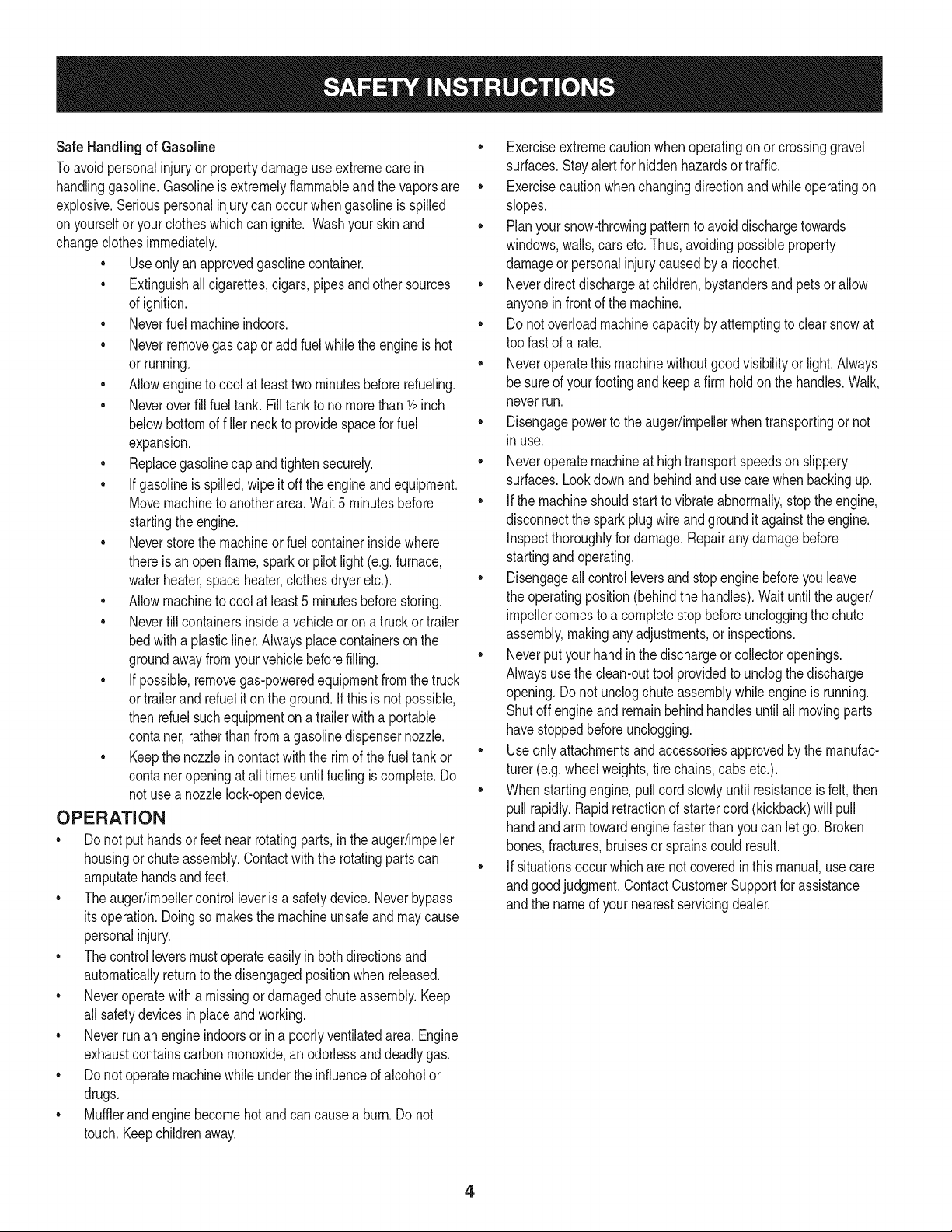
Safe Handling of Gasoline
Toavoidpersonalinjuryor propertydamageuseextremecare in
handlinggasoline.Gasolineis extremelyflammableandthe vaporsare
explosive.Seriouspersonalinjurycan occurwhengasolineis spilled
onyourselfor yourclotheswhichcan ignite.Washyour skinand
changeclothesimmediately.
• Useonly an approvedgasolinecontainer.
• Extinguishall cigarettes,cigars,pipesand other sources
of ignition.
• Neverfuelmachineindoors.
• Neverremovegas capor add fuel whilethe engineis hot
or running.
• Allowengineto coolat leasttwo minutesbeforerefueling.
• Neveroverfill fueltank. Filltank to no morethan1/2inch
belowbottomof filler neckto providespacefor fuel
expansion.
• Replacegasolinecap andtightensecurely.
• If gasolineis spilled,wipeit off the engineand equipment.
Movemachineto anotherarea.Wait5 minutesbefore
startingthe engine.
• Neverstorethe machineor fuel containerinsidewhere
thereis anopen flame,sparkor pilotlight (e.g.furnace,
waterheater,spaceheater,clothesdryer etc.).
• Allowmachineto cool at least5 minutesbeforestoring.
• Neverfill containersinsidea vehicleor ona truckor trailer
bedwith a plasticliner.Alwaysplacecontainerson the
groundawayfromyourvehiclebeforefilling.
• If possible,removegas-poweredequipmentfromthetruck
ortrailerand refuelit on the ground.If thisis not possible,
then refuelsuchequipmenton a trailerwitha portable
container,ratherthan froma gasolinedispensernozzle.
• Keepthe nozzlein contactwiththe rimof the fueltankor
containeropeningat all timesuntil fuelingis complete.Do
notuse a nozzlelock-opendevice.
OPERATION
• Do not puthandsorfeet near rotatingparts,in the auger/impeller
housingor chuteassembly.Contactwiththe rotatingpartscan
amputatehandsand feet.
• Theauger/impellercontrolleveris a safetydevice.Neverbypass
itsoperation.Doingso makesthe machineunsafeandmay cause
personalinjury.
• Thecontrol leversmustoperateeasilyin bothdirectionsand
automaticallyreturnto the disengagedpositionwhenreleased.
• Neveroperatewitha missingor damagedchuteassembly.Keep
all safetydevicesin placeandworking.
• Neverrunan engineindoorsor ina poorlyventilatedarea. Engine
exhaustcontainscarbonmonoxide,anodorlessand deadlygas.
• Do notoperatemachinewhileunderthe influenceof alcoholor
drugs.
• Mufflerandenginebecomehotand can causea burn.Do not
touch.Keepchildrenaway.
• Exerciseextremecautionwhenoperatingon or crossinggravel
surfaces.Stayalertfor hiddenhazardsor traffic.
• Exercisecautionwhenchangingdirectionandwhileoperatingon
slopes.
• Planyoursnow-throwingpatternto avoiddischargetowards
windows,walls,carsetc. Thus,avoidingpossibleproperty
damageor personalinjurycausedby a ricochet.
• Neverdirect dischargeat children,bystandersand petsor allow
anyoneinfront of the machine.
• Donot overloadmachinecapacityby attemptingto clearsnowat
too fastof a rate.
• Neveroperatethis machinewithoutgoodvisibilityor light.Always
be sureof yourfootingand keepa firmhold on the handles.Walk,
neverrun.
• Disengagepowerto theauger/impellerwhentransportingor not
in use.
• Neveroperatemachineat high transportspeedson slippery
surfaces.Lookdownand behindand usecare whenbackingup.
• If the machineshouldstart to vibrateabnormally,stop the engine,
disconnectthe sparkplugwire and groundit againstthe engine.
Inspectthoroughlyfor damage.Repairanydamagebefore
startingandoperating.
• Disengageall controlleversand stopenginebeforeyouleave
the operatingposition(behindthe handles).Waituntilthe auger/
impellercomesto a completestop beforeuncloggingthechute
assembly,makingany adjustments,or inspections.
• Neverput yourhand inthe dischargeor collectoropenings.
Alwaysusethe clean-outtool providedto unclogthedischarge
opening.Donot unclogchuteassemblywhileengine is running.
Shutoff engineand remainbehindhandlesuntilallmovingparts
havestoppedbeforeunclogging.
• Useonly attachmentsand accessoriesapprovedby the manufac-
turer (e.g.wheelweights,tire chains,cabsetc.).
• Whenstartingengine,pullcord slowlyuntilresistanceis felt, then
pull rapidly.Rapidretractionof startercord(kickback)will pull
handand armtowardenginefasterthan youcan let go. Broken
bones,fractures,bruisesor sprainscould result.
• If situationsoccurwhichare notcoveredinthis manual,use care
andgood judgment.ContactCustomerSupportfor assistance
andthe nameof your nearestservicingdealer.
4
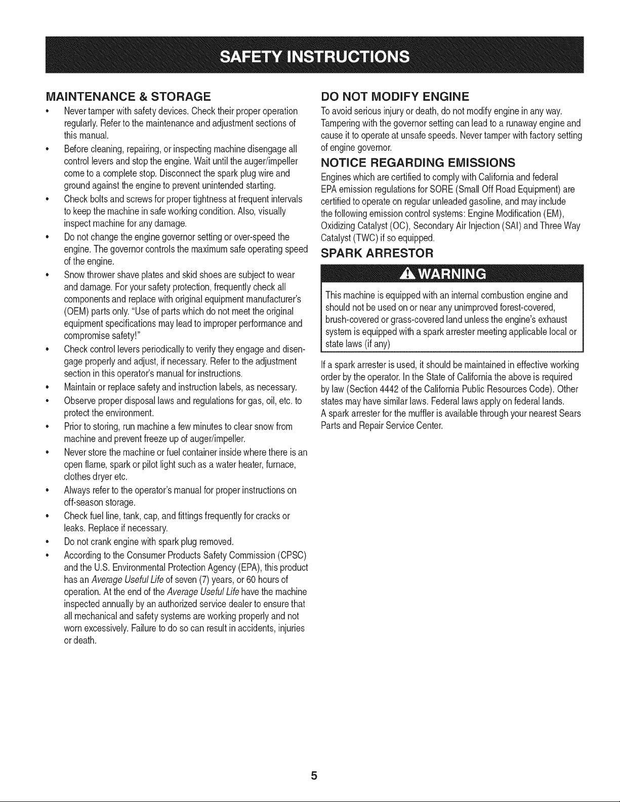
MAINTENANCE & STORAGE
• Nevertamperwithsafetydevices.Checktheirproperoperation
regularly.Referto the maintenanceand adjustmentsectionsof
thismanual.
• Beforecleaning,repairing,or inspectingmachinedisengageall
controlleversandstop the engine.Waituntilthe auger/impeller
cometo a completestop.Disconnectthe sparkplug wireand
groundagainsttheengineto preventunintendedstarting.
Checkboltsand screwsfor propertightnessat frequentintervals
to keepthe machinein safeworkingcondition.Also,visually
inspectmachinefor anydamage.
Do notchangetheenginegovernorsettingor over-speedthe
engine.Thegovernorcontrolsthe maximumsafeoperatingspeed
of the engine.
Snowthrowershaveplatesand skidshoesare subjectto wear
anddamage.Foryoursafetyprotection,frequentlycheckall
componentsand replacewithoriginalequipmentmanufacturer's
(OEM)partsonly."Useof parts whichdo not meetthe original
equipmentspecificationsmayleadto improperperformanceand
compromisesafety!"
Checkcontrolleversperiodicallyto verifythey engageanddisen-
gageproperlyandadjust,if necessary.Referto the adjustment
sectioninthisoperator'smanualfor instructions.
Maintainor replacesafetyandinstructionlabels,as necessary.
• Observeproperdisposallawsand regulationsfor gas,oil,etc. to
protectthe environment.
Priorto storing,runmachinea few minutestoclear snowfrom
machineand preventfreezeupof auger/impeller.
Neverstorethe machineor fuel containerinsidewherethereisan
openflame,sparkor pilot lightsuch as a waterheater,furnace,
clothesdryer etc.
Alwaysreferto the operator'smanualfor properinstructionson
off-seasonstorage.
Checkfuelline,tank, cap,and fittingsfrequentlyfor cracksor
leaks.Replaceif necessary.
Do notcrankenginewith sparkplugremoved.
Accordingto the ConsumerProductsSafetyCommission(CPSC)
andthe U.S.EnvironmentalProtectionAgency(EPA),this product
hasan AverageUsefulLifeof seven(7) years,or 60 hoursof
operation.At the endof theAverageUsefulLifehavethe machine
inspectedannuallybyan authorizedservicedealerto ensurethat
allmechanicalandsafetysystemsare workingproperlyand not
wornexcessively.Failureto do so can resultin accidents,injuries
ordeath.
DO NOT MODIFY ENGINE
Toavoidseriousinjuryor death,do not modifyenginein any way.
Tamperingwiththe governorsettingcanleadto a runawayengineand
causeit to operateat unsafespeeds.Nevertamperwithfactorysetting
of enginegovernor.
NOTICE REGARDING EMISSIONS
Engineswhich arecertifiedtocomplywithCaliforniaand federal
EPAemissionregulationsfor SORE(SmallOff RoadEquipment)are
certifiedto operateon regularunleadedgasoline,and mayinclude
the followingemissioncontrolsystems:EngineModification(EM),
OxidizingCatalyst(OC), SecondaryAir Injection(SAI)and ThreeWay
Catalyst(TWO)if so equipped.
SPARK ARRESTOR
Thismachineisequippedwith aninternalcombustionengineand
shouldnotbe usedonor nearany unimprovedforest-covered,
brush-coveredor grass-coveredland unlessthe engine'sexhaust
systemisequippedwitha sparkarrestermeetingapplicablelocalor
statelaws(if any)
Ifa sparkattester is used, it shouldbe maintainedin effectiveworking
orderby theoperator.Inthe State of Californiathe aboveis required
bylaw (Section4442of the CaliforniaPublicResourcesCode). Other
statesmayhavesimilarlaws. Federallawsapplyonfederallands.
A sparkarresterfor the muffleris availablethroughyournearestSears
PartsandRepairServiceCenter.
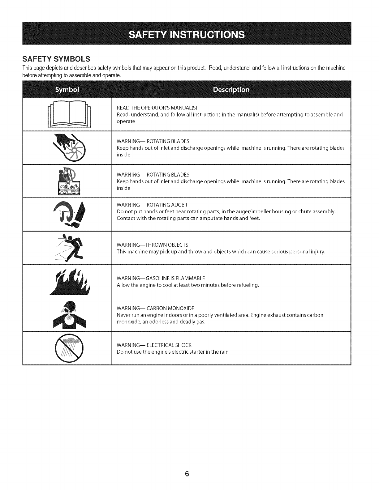
SAFETY SYMBOLS
Thispagedepictsand describessafetysymbolsthatmayappear onthis product. Read,understand,andfollowall instructionson the machine
beforeattemptingto assembleand operate.
i
i
READ THE OPERATOR'S MANUAL(S)
Read, understand, and follow all instructions in the manual(s) before attempting to assemble and
operate
WARNING-- ROTATING BLADES
Keep hands out of inlet and discharge openings while machine is running. There are rotating blades
inside
WARNING-- ROTATING BLADES
Keep hands out of inlet and discharge openings while machine is running. There are rotating blades
inside
WARNING-- ROTATING AUGER
Do not put hands or feet near rotating parts, in the auger/impeller housing or chute assembly.
Contact with the rotating parts can amputate hands and feet.
WARNING--THROWN OBJECTS
This machine may pick up and throw and objects which can cause serious personal injury.
WARNING--GASOLINE IS FLAMMABLE
Allow the engine to cool at least two minutes before refueling.
WARNING-- CARBON MONOXIDE
Never run an engine indoors or in a poorly ventilated area. Engine exhaust contains carbon
monoxide, an odorless and deadly gas.
WARNING-- ELECTRICAL SHOCK
Do not use the engine's electric starter in the rain
6
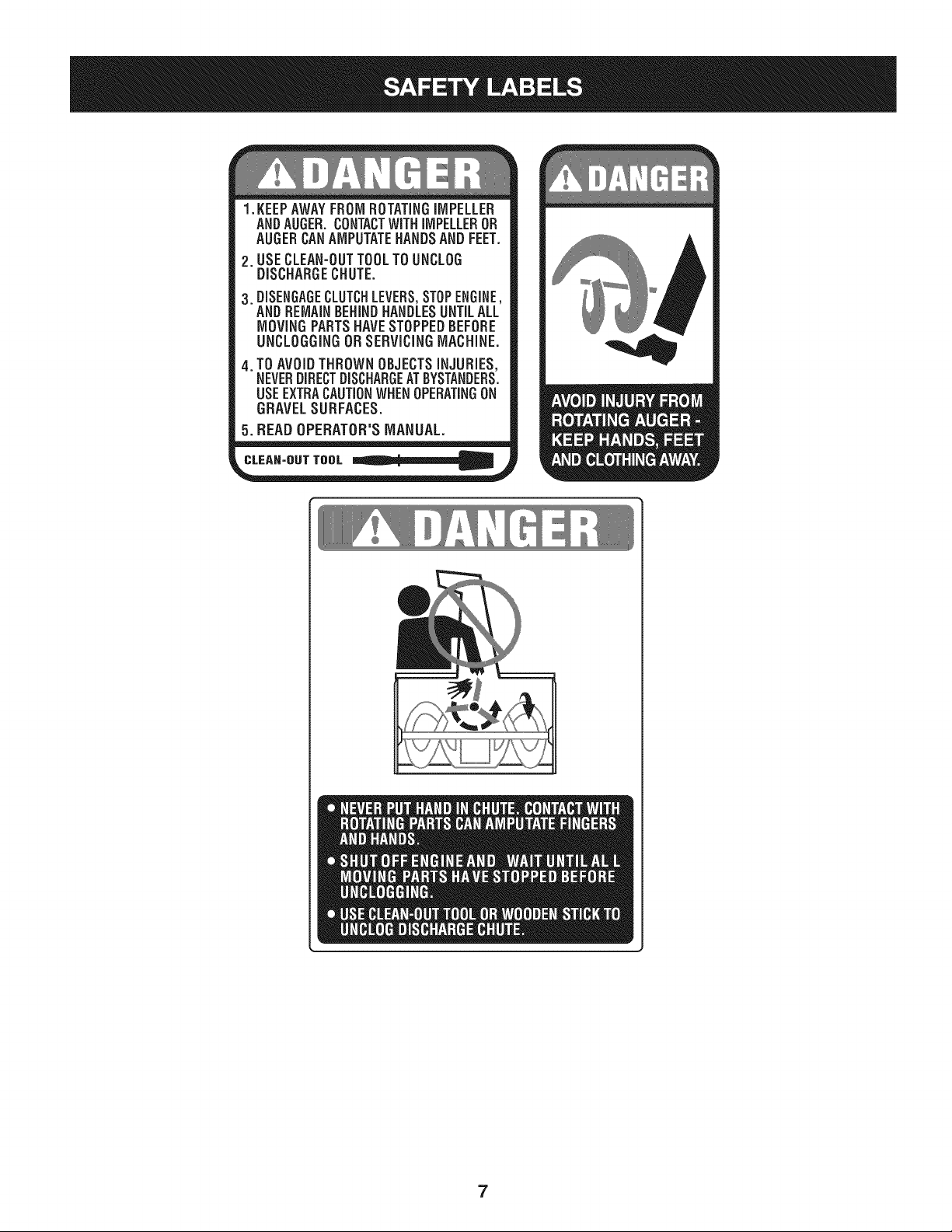
1.KEEPAWAYFROMROTATINGiMPELLER
ANDAUGER,CONTACTWiTHiMPELLEROR
AUGERCANAMPUTATEHANDSANDFEET.
2. USECLEAN-OUTTOOLTOUNCLOG
DISCHARGECHUTE.
3.DISENGAGECLUTCHLEVERS,STOPENGINE,
AND REMAINBEHINDHANDLESUNTILALL
MOVING PARTSHAVE STOPPEDBEFORE
UNCLOGGING OR SERViCiNGMACHINE.
TO AVOIDTHROWN OBJECTSiNJURiES,
NEVERDIRECTDISCHARGEATBYSTANDERS.
USEEXTRACAUTIONWHEN OPERATINGON
GRAVEL SURFACES.
5.BEAD OPERATOR'S MANUAL.
CLEAN-OUT TOOL
7
NOTE:Referencesto rightorleft sideof the snowthrowerare
determinedfrombehindthe unit in the operatingposition(standing
directlybehindthe snowthrower,facingthe handlepanel).
REMOVING FROM CARTON
1. Cut the cornersof thecarton andlay the sidesflaton the ground.
Removeand discardall packinginserts.
2. Movethe snowthrowerout of thecarton.
3. Makecertainthe carton has beencompletelyemptiedbefore
discardingit.
ASSEMBLY
1. Observethe lowerreararea of the snowthrowerto be sure both
cablesarealignedwith rollerguidesbeforepivotingthe handle
upward.
a. Placethe shiftleverin the F6position.
b. Pull upandbackon upperhandleas shownin Figure1.As
youare raisingthe handleupward,makesurethat bothends
of the centercablearepositionedproperlyin the brackets.
Alignupperhandlewith the lowerhandle.
c. Tightenhandknobssecuringupper handleto lowerhandle.
Removeand discardany rubberbands,if present.Theyare
for packagingpurposesonly.
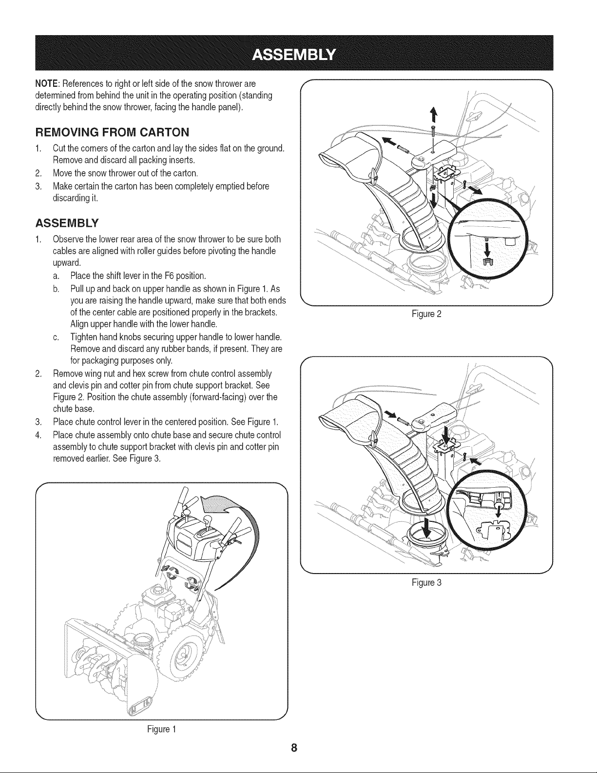
2. Removewingnut andhexscrewfrom chutecontrolassembly
andclevispin andcotter pinfromchutesupportbracket.See
Figure2. Positionthe chuteassembly(forward-facing)overthe
chutebase.
3. Placechutecontrol leverinthe centeredposition.SeeFigure1.
4. Placechuteassemblyontochutebaseand securechutecontrol
assemblyto chutesupportbracketwithclevispin and cotterpin
removedearlier.See Figure3.
f
Figure2
Figure1
8
Figure3
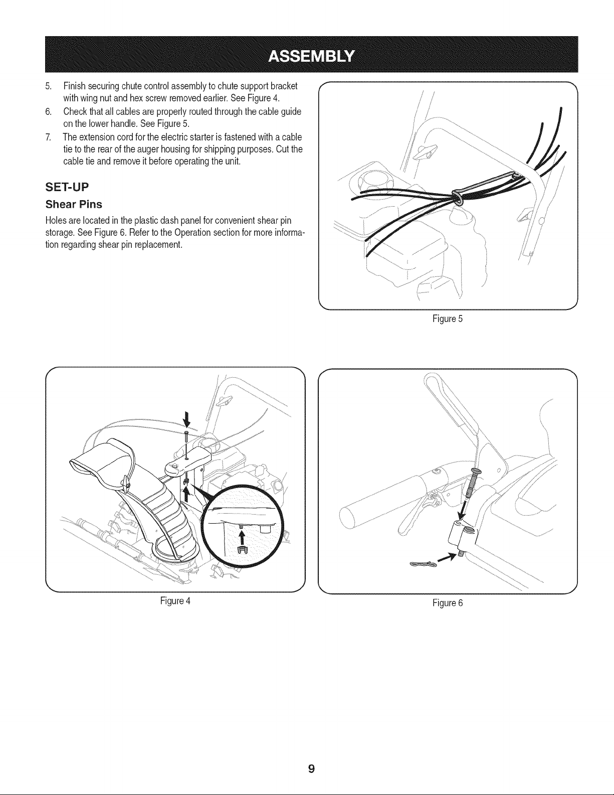
5. Finishsecuringchutecontrolassemblytochutesupportbracket
withwingnutandhexscrewremovedearlier.SeeFigure4.
6. Checkthatallcablesareproperlyroutedthroughthecableguide
onthelowerhandle.SeeFigure5.
7. Theextensioncordfortheelectricstarterisfastenedwithacable
tietotherearoftheaugerhousingforshippingpurposes.Cutthe
cabletieandremoveitbeforeoperatingtheunit.
SET-UP
Shear Pins
Holesare locatedinthe plasticdashpanelfor convenientshearpin
storage.SeeFigure6. Referto the Operationsectionfor moreinforma-
tion regardingshearpinreplacement.
Figure5
f
/
\
Figure4
Figure6
J
9
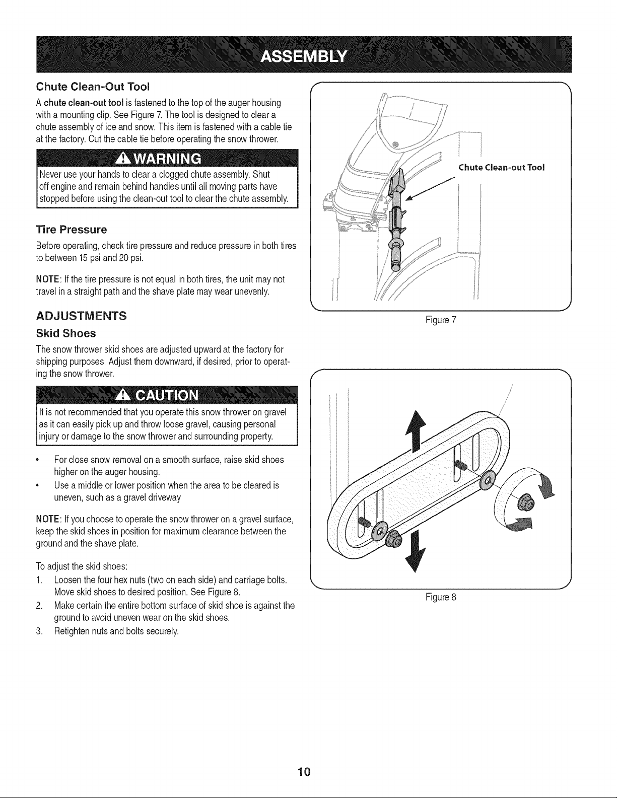
Chute Clean-Out Tool
A chute clean-out tool is fastenedto the topof the augerhousing
witha mountingclip. SeeFigure7.The tool is designedto cleara
chuteassemblyof ice and snow.Thisitemis fastenedwith acable tie
at the factory.Cutthe cabletie beforeoperatingthe snowthrower.
Neveruseyour handsto cleara cloggedchuteassembly.Shut
loft engineand remainbehindhandlesuntilall movingpartshave
[stoppedbeforeusingthe clean-outtool to clearthe chuteassembly.
Tire Pressure
Beforeoperating,checktire pressureandreducepressurein bothtires
to between15psi and 20 psi.
NOTE:Ifthe tire pressureis not equal inboth tires,the unitmaynot
travelin a straightpathandthe shaveplatemaywear unevenly.
ADJUSTMENTS
Skid Shoes
The snowthrowerskidshoesare adjustedupwardat the factoryfor
shippingpurposes.Adjustthemdownward,if desired,prior to operat-
ingthe snowthrower.
lit is not recommendedthat this thrower
you operate
snow on
gravel
as it can easilypickup andthrow loosegravel,causingpersonal
injuryordamageto the snowthrowerandsurroundingproperty.
• Forclose snowremovalon a smoothsurface,raiseskid shoes
higheronthe augerhousing.
• Usea middleor lowerpositionwhenthe areato be clearedis
uneven,suchasa graveldriveway
NOTE:Ifyouchooseto operatethe snowthroweron a gravelsurface,
keepthe skidshoesin positionfor maximumclearancebetweenthe
groundandthe shaveplate.
To adjustthe skid shoes:
1. Loosenthefour hex nuts(two on eachside)andcarriagebolts.
Moveskidshoesto desiredposition.SeeFigure8.
2. Makecertainthe entirebottomsurfaceof skidshoe is againstthe
groundto avoid unevenwearon the skidshoes.
3. Retightennutsandboltssecurely.
Chute Clean=out Tool
Figure7
/
/
/
Figure8
10
Auger Control
Priorto operatingyoursnowthrower,carefullyreadand followall
instructionsbelow.Performall adjustmentsto verifyyour snow
throweris operatingsafelyand properly.
Checktheadjustmentof the augercontrolas follows:
1. Whentheaugercontrolis releasedandin the disengaged"up"
position,the cableshouldhavevery little slack.It shouldNOTbe
tight.
2. In a well-ventilatedarea,start the snowthrowerengine.Referto
Startingthe Enginein the Operationsection.
3. Whilestandingin the operator'sposition(behindthe snow
thrower),engagethe auger.
4. Allowtheauger to remainengagedfor approximatelyten (10)
secondsbeforereleasingthe augercontrol.Repeatthis several
times.
5. With theaugercontrolin thedisengaged"up" position,walkto the
frontof the machine.
6. Confirmthatthe augerhas completelystoppedrotatingand
showsNOsignsof motion.If the augershowsANYsignsof
rotating,immediatelyreturnto the operator'spositionandshutoff
the engine.Waitfor ALLmovingpartsto stopbeforeadjustingthe
augercontrol.
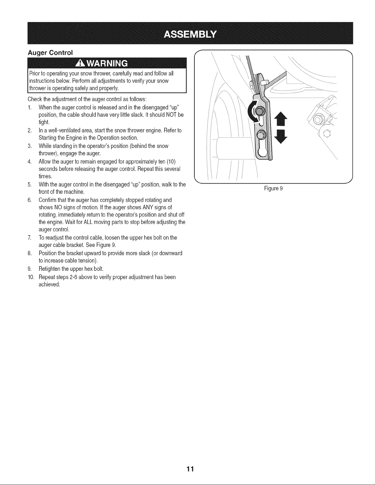
7. Toreadjustthecontrolcable, loosentheupperhexbolt onthe
augercablebracket.SeeFigure9.
8. Positionthe bracketupwardto providemoreslack(or downward
to increasecabletension).
9. Retightenthe upperhex bolt.
10. Repeatsteps2-6 aboveto verifyproperadjustmenthasbeen
achieved.
f
Figure9
11
f
Drive Control
Shift Lever
/
Four=WayChuteControP
/_ AugerControl
Chute Assembly
\
\
Gas Cap
'\
OU Fill
\
Wheel Steering Control
Clean Out
Tool
\
Augers Skid Shoe
Choke
Recoil Starter
Handle
Electric Star
Button
Key
Stop Switch
Electric
Starter
Outlet
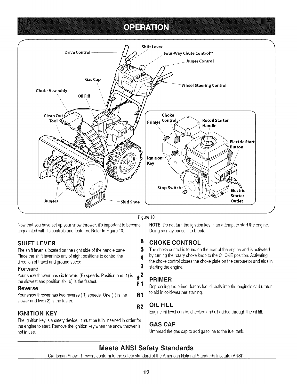
Figure10
Nowthat youhavesetup yoursnowthrower,it's importantto become NOTE: Donot turnthe ignitionkey inan attemptto startthe engine.
acquaintedwith itscontrolsandfeatures.Referto Figure10. Doingso maycauseit to break.
SHIFT LEVER
The shiftleveris locatedon the rightsideof the handle panel.
Placethe shiftleverinto anyof eightpositionsto controlthe
directionof traveland groundspeed.
Forward
6 CHOKE CONTROL
5 The chokecontrolisfoundon the rearof the engineand isactivated
4 by turningthe rotarychokeknobto the CHOKEposition.Activating
the chokecontrolclosesthe choke plateon thecarburetorandaids in
3 startingthe engine.
Yoursnowthrowerhas six forward(F) speeds.Positionone(1)is t 2
the slowestand positionsix (6) is the fastest. F 1
Reverse
Yoursnowthrowerhastwo reverse(R) speeds.One(1) is the
slowerandtwo (2) is the faster.
IGNITION KEY
The ignitionkeyis a safetydevice.It mustbefully insertedinorder for
theengineto start. Removethe ignitionkeywhenthe snowthroweris
not inuse.
PRIMER
Depressingthe primerforcesfueldirectlyintothe engine'scarburetor
to aid incold-weatherstarting.
OIL FILL
Engineoil levelcan becheckedandoil addedthroughthe oil fill.
GAS CAP
Unthreadthe gas capto add gasolineto thefuel tank.
Meets ANSi Safety Standards
CraftsmanSnowThrowersconformto the safetystandardof the AmericanNationalStandardsInstitute(ANSI).
12
STOP SWITCH
Pressinto theON positionwhenstartingthe engineand willshutoff
the enginewhenmovedintothe OFF position.
RECOIL STARTER HANDLE
Thishandleis usedto manuallystartthe engine.
ELECTRIC STARTER BUTTON
Pressingthe electricstarterbuttonengagesthe engine'selectric
starterwhenpluggedintoa 120Vpowersource.
ELECTRIC STARTER OUTLET
Requiresthe useof athree-prongoutdoorextensioncord(included)
anda 120Vpowersource/walloutlet.
AUGERS
Whenengaged,the augersrotateanddrawsnowintothe auger
housing.
SKID SHOES
Positionthe skid shoesbasedon surfaceconditions.Adjust upward
for hard-packedsnow.Adjustdownwardwhenoperatingon gravelor
crushedrocksurfaces.
CHUTE ASSEMBLY
Snowdrawninto theaugerhousingis dischargedout the chute
assembly.
WHEEL STEERING CONTROLS
Theleft andrightwheelsteeringcontrolsare locatedon theunderside
of the handles.Squeezethe rightcontrolto turn right;squeezethe left
controlto turn left.
NOTE:Operatethe snowthrowerinopenareasuntilyou are familiar
withthesecontrols.
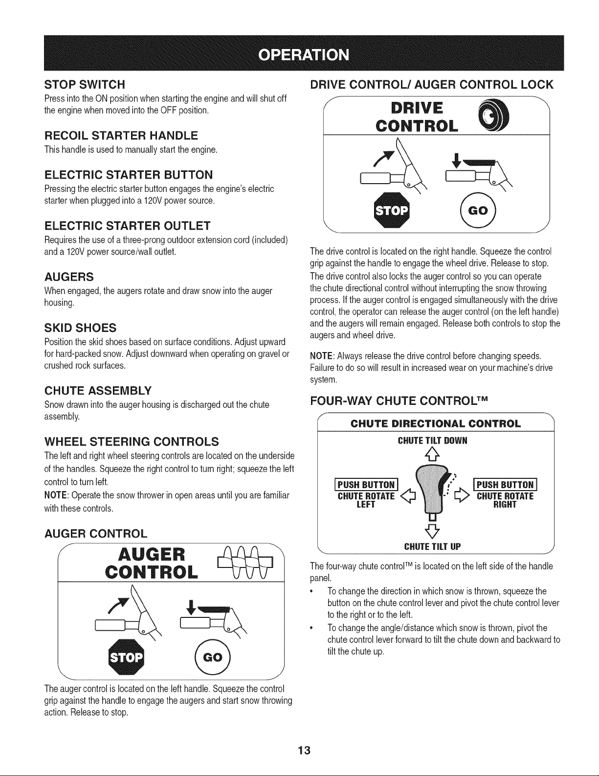
AUGER CONTROL
J AUGER
CONTROL
Theaugercontrolis locatedon the left handle.Squeezethecontrol
gripagainstthe handleto engagetheaugersandstart snowthrowing
action.Releaseto stop.
DRIVE CONTROL/AUGER CONTROL LOCK
The drivecontrolis locatedon the righthandle.Squeezethe control
gripagainstthe handleto engagethe wheeldrive.Releaseto stop.
The drivecontrolalso lockstheauger controlso youcan operate
the chutedirectionalcontrolwithoutinterruptingthe snowthrowing
process.If the augercontrolis engagedsimultaneouslywiththe drive
control,the operatorcan releasethe augercontrol (onthe lefthandle)
andthe augerswill remainengaged.Releaseboth controlsto stop the
augersandwheeldrive.
NOTE:Alwaysreleasethedrivecontrol beforechangingspeeds.
Failureto do so will result inincreasedwearon yourmachine'sdrive
system.
FOUR-WAY CHUTE CONTROL TM
f
CHUTE DiRECTiONAL CONTROL
CHUTETiLTgOWN
jPUSH HUTTOHi
CHUTEROTATE_
LEFT
jPUSH HUTTOHi
_ CHUTENOTATE
HIGHT
©
_.. CHUTETiLTUP j
The four-waychutecontrolTM iSlocatedonthe left sideof the handle
panel.
* Tochangethe directionin whichsnowis thrown,squeezethe
buttononthe chutecontrol leverand pivotthe chutecontrollever
to the rightorto the left.
* Tochangethe angle/distancewhich snowisthrown,pivotthe
chutecontrolleverforwardto tilt the chute downand backwardto
tilt the chuteup.
13
CLEAN-OUT TOOL
Neveruseyourhandsto cleara cloggedchuteassembly.Shut
loft engineand remainbehindhandlesuntil all movingpartshave
lstoppedbeforeusingtheclean-outtool to clearthe chuteassembly.
Thechuteclean-outtool is convenientlyfastenedto the rear of the
augerhousingwitha mountingclip. Shouldsnowand ice become
lodgedin thechuteassemblyduringoperation,proceedas followsto
safelycleanthechuteassemblyand chuteopening:
1. Releaseboththe AugerControlandthe DriveControl.
2. Stopthe engineby removingthe ignitionkey.
3. Removethe clean-outtoolfromthe clip whichsecuresit to the
rearof the augerhousing.
4. Use the shovel-shapedendof theclean-outtool to dislodgeand
scoopany snowand icewhich hasformedin andnear thechute
assembly.
5. Refastenthe clean-outtool to the mountingclip on the rear of
theaugerhousing,reinsertthe ignitionkey andstartthe snow
thrower'sengine.
6. Whilestandingin the operator'sposition(behindthesnow
thrower),engagethe augercontrolfora fewsecondsto clear any
remainingsnowandice from thechuteassembly.
BEFORE STARTING ENGINE
Read,understand,and followall instructionsandwarningson the
machineand inthis manualbeforeoperating.
Oil
The unitwasshippedwithoil in the engine.Checkoil levelbeforeeach
operationto ensureadequateoilin the engine.Forfurther instructions,
referto the stepson page16.
1. Removethe dipstickfromthe oil fill.
2. Checkand makesurethatthe levelof oil is up to the FULLmark
onthe dipstick.
3. If the oil levelis not up to FULL,pourfresh motoroil (5W-30,with
a minimumclassificationof SF/SG/SH/SJ)slowlythroughthe
opening.Replaceoil fill dipstickandcheckoil levelagain.
Gasoline
o Storegasolinein aclean,approvedcontainerandkeepthecap in
placeonthe container.
• Makesurethatthe containerfromwhichyoupourthe gasolineis
cleanandfreefrom rustor otherforeignparticles.
Useextremecarewhen handlinggasoline.Gasolineis extremely
flammableandthevaporsare explosive.Never fuelthe machine
indoorsorwhilethe engine is hotor running.Extinguishcigarettes,
cigars,pipesandothersourcesof ignition.
Alwaysfill the fuel tankoutdoorsand usea funnelor spoutto
preventspilling.
• Fillfuel tank withclean,fresh,unleadedgasolinewith a minimum
of 85 octane.Freshfuel preventsgumfromforminginthe fuel
systemoron essentialcarburetorparts.Purchasefuelin a
quantitythatcan be usedwithin30 days.
• Neverfill the fuel tank completely.Fillthe tankto within 1-1/2"
fromthe top to providespacefor expansionof fuel.
• Makesureto wipeoff anyspilledfuel beforestartingthe engine.
STARTING THE ENGINE
1. Makecertainboththe augercontrolanddrivecontrolarein the
disengaged(released)position.
2. Insertignitionkeyinto slot.Makesure it snapsinto place.Do not
attemptto turn the key.
NOTE: Theenginecannotstartwithoutthe keyis fully insertedintothe
ignitionswitch.
Electric Starter
Determinethat yourhome'swiringis a three-wiregroundedsystem.
Aska licensedelectricianif you arenotcertain.
Theoptionalelectricstarteris equippedwitha groundedthree-wire
powercordand plug,andis designedto operateon 120voltAC
householdcurrent.It mustbe usedwitha properlygroundedthree-
prongreceptacleat alltimesto avoidthe possibilityof electricshock.
Followall instructionscarefullypriorto operatingthe electricstarter.
DO NOTuseelectricstarterin the rain.
Ifyou havea groundedthree-prongreceptacle,proceedas follows:
1. Plugthe extensioncord intothe outlet locatedon the engine's
surface.Plugthe otherendof extensioncord intoa three-prong
120-volt,grounded,AC outlet ina well-ventilatedarea.
2. Rotatechokecontrolto CHOKEI,._¢1position.
3. Depressprimer.If it is 15°For higherpushprimertwotimes, if
below 15°F,pushprimerfour times.
14
4. PushStopswitchto ONposition.
5. Pushstarterbuttonto start engine.
2. Squeezethe drivecontrolagainstthe handleandthe snow
throwerwill move.Releaseit anddrive motionwill stop.
To prolongstarterlife,useshort startingcycles(5 secondsmaximum
then waitone minute).
6. Oncethe enginestarts,releasestarterbutton.
7. Allowtheengine to warmup severalminutes,adjustingchoke
towardRUNposition.Waituntilengineruns smoothlybeforeeach
chokeadjustment.
8. Whendisconnectingthe extensioncord,alwaysunplugthe end
at the three-prongwalloutlet beforeunpluggingthe oppositeend
fromthe snowthrower.
Recoil Starter
1. Rotatechokecontrolto CHOKE IJl position.
2. Depressprimer.Ifit is 15°For higherpushprimertwotimes,if
below15°F,pushprimerfourtimes.
3. PushStopswitchto ONposition.
4. Graspthe recoilstarterhandleand slowlypull the ropeout.At
the pointwhereit becomesslightlyharderto pullthe rope,slowly
allowthe ropeto recoil.
5. Pull the starterhandlewith a firm, rapid stroke.Donot release
the handleandallowit to snap back.Keepa firm holdonthe
starterhandleandallowit to slowlyrecoil.
6. Allowtheengine to warmup severalminutes,adjustingchoke
towardRUNposition.Waituntilengineruns smoothlybeforeeach
chokeadjustment.
STOPPING THE ENGINE
Afteryouare finishedsnow-throwing,runenginefor a fewminutes
beforestoppingto help dry offany moistureonthe engine.
1. PushStopswitchto OFFposition.
2. Removetheignitionkeyand storein a safeplace.
3. Wipeall snowand moisturefromthearea aroundthe engineas
wellas the areain andaroundthe drivecontrolandaugercontrol.
Also,engageand releasebothcontrolsseveraltimes.
TO ENGAGE DRIVE
1. Moveshift leverintooneof the six forward(F) positionsor two
reverse(R) positions.Selecta speedappropriatefor the snow
conditionsand a paceyou'recomfortablewith.
NOTE: Whenselectinga DriveSpeed,usethe slowerspeedsuntil
youarecomfortableand familiarwiththe operationof the snow
thrower.
NOTE:NEVERrepositiontheshift lever(changespeedsor direction
of travel)withoutfirst releasingthe drivecontroland bringingthe snow
throwerto a completestop.Doingsowill resultin prematurewearto
the snowthrower'sdrivesystem.
TO ENGAGE AUGERS
1. Toengagethe augersand startthrowingsnow,squeezethe
augercontrolagainstthe left handle.Releaseto stop theaugers.
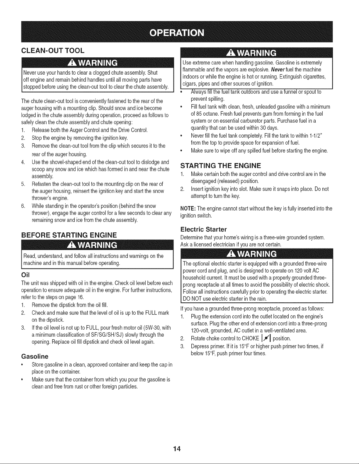
REPLACING SHEAR PINS
The augersare securedto the spiralshaftwithfour shearpinsand
bow-tieclips. Ifthe augershouldstrikea foreignobjector icejam,
the snowthroweris designedsothat the shearpins mayshear.If the
augerswill notturn,checkto see if the pins havesheared.See Figure
11.
NEVERreplacethe augershearpinswithanythingotherthan Sears
PartNo.88389replacementshearpins.Any damageto the auger
gearboxor othercomponentsas a resultof failingto doso will NOT
becoveredby yoursnow thrower'swarranty.
Alwaysturn off thesnowthrower'sengineand removethe key priorto
replacingshearpins.
\\
/
/ ©
Figure11
J
15
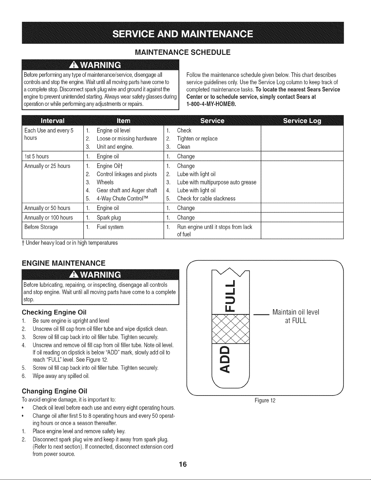
MAINTENANCE SCHEDULE
Beforeperforminganytypeof maintenance/service,disengageall
controlsand stoptheengine.Waituntilall movingpartshavecometo
acompletestop.Disconnectsparkplugwireandgrounditagainstthe
enginetopreventunintendedstarting.Alwayswearsafetyglassesduring
operationor whileperforminganyadjustmentsor repairs.
Followthe maintenanceschedulegivenbelow.This chartdescribes
serviceguidelinesonly.Usethe ServiceLogcolumnto keeptrackof
completedmaintenancetasks.To locate the nearest Sears Service
Centeror to scheduleservice,simplycontactSears at
1-800-4-MY-HOME®.
EachUseand every5
hours
1st5 hours
Annuallyor25 hours
Annuallyor50 hours
Annuallyor 100hours
BeforeStorage
1 Underheavyloador in hightemperatures
1. Engineoil level
2. Looseor missinghardware
3. Unitandengine.
1. Engineoil
1. Engine0i11-
2. Controllinkagesandpivots
3. Wheels
4. GearshaftandAugershaft
5. 4-Way ChuteControlTM
1. Engineoil
1. Sparkplug
1. Fuelsystem
1. Check
2. Tightenor replace
3. Clean
1. Change
1. Change
2. Lubewith lightoil
3. Lubewith multipurposeautogrease
4. Lubewith lightoil
5. Checkfor cableslackness
1. Change
1. Change
1. Runengineuntilit stopsfrom lack
of fuel
ENGINE MAINTENANCE
lBefore lubricating,repairing,or inspecting,disengage
all controls
and stopengine.Waituntil all movingparts havecometo a complete
stop.
Checking Engine Oil
1. Be sureengineis uprightand level
2. Unscrewoil fill cap from oilfiller tubeand wipe dipstickclean.
3. Screwoil fill cap back intooil fillertube.Tightensecurely.
4. Unscrewand removeoil fill cap fromoil fillertube. Noteoil level.
Ifoil readingon dipstickis below"ADD"mark,slowlyaddoilto
reach"FULL"level.SeeFigure12.
5. Screwoil fill cap back intooil fillertube.Tightensecurely.
6. Wipeawayanyspilledoil.
Changing Engine Oil
Toavoidenginedamage,it is importantto:
• Checkoil levelbeforeeach useandeveryeightoperatinghours.
• Changeoilafter first 5 to 8 operatinghoursandevery50operat-
inghoursor once a seasonthereafter.
1. Placeengineleveland removesafetykey.
2. Disconnectsparkplugwire and keepit awayfrom sparkplug.
(Referto nextsection).If connected,disconnectextensioncord
frompowersource.
f
16
,,.J
,,,,J
13
13
Maintain oil level
at FULL
Figure12
J
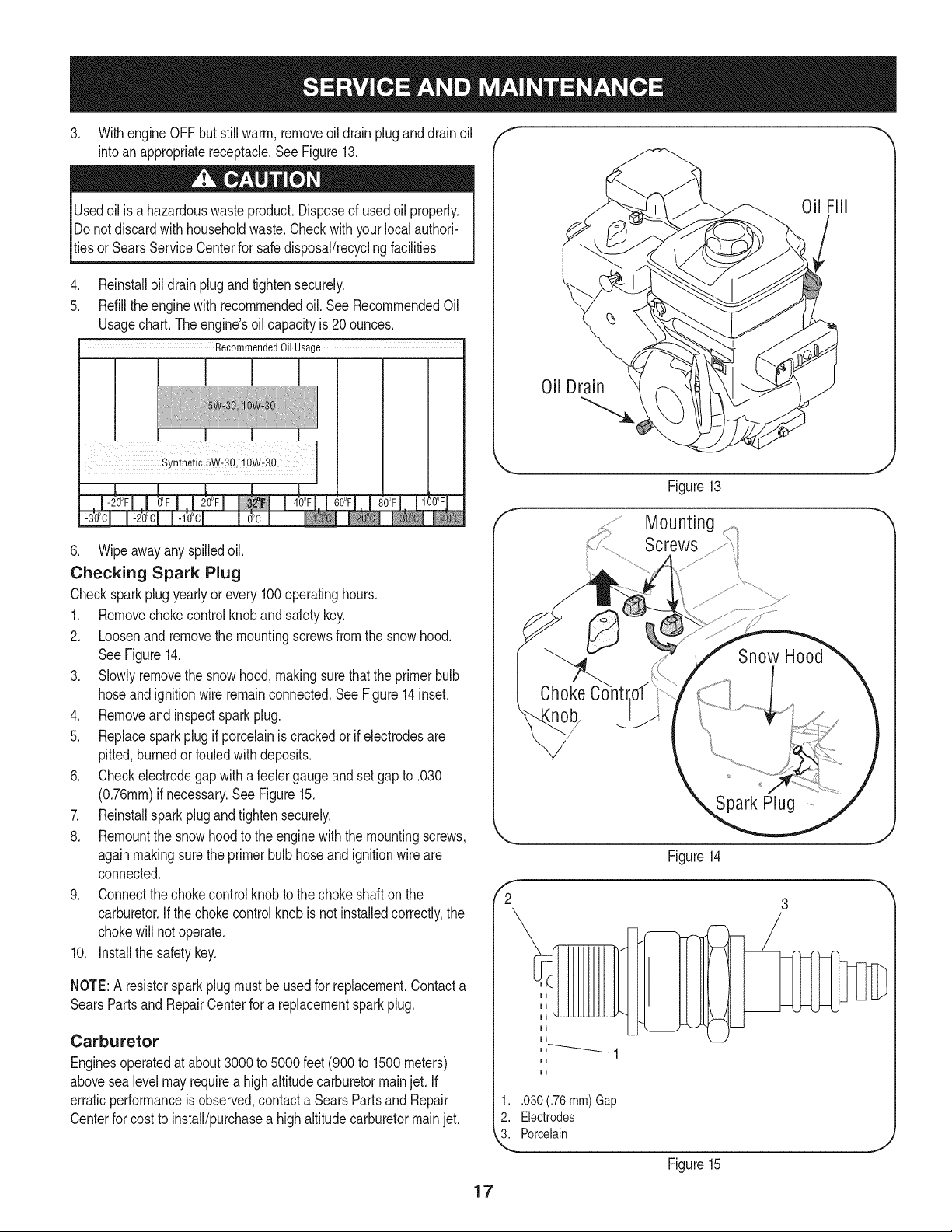
3. WithengineOFFbutstillwarm,removeoildrainpluganddrainoil
intoanappropriatereceptacle.SeeFigure13.
Usedoilisahazardouswasteproduct.Disposeofusedoilproperly.
Donotdiscardwithhouseholdwaste.Checkwithyourlocalauthori-
tiesorSearsServiceCenterforsafedisposal/recyclingfacilities.
.
5.
Reinstalloildrainplugand tightensecurely.
Refillthe enginewith recommendedoil. SeeRecommendedOil
Usagechart.The engine'soil capacityis 20ounces.
Recommended Oil Usage
I
SiUiheiic 5W 3Q:i O_io
6. Wipeawayany spilledoil.
Checking Spark Plug
Checksparkplugyearlyor every 100operatinghours.
1. Removechokecontrolknobandsafetykey.
2. Loosenand removethe mountingscrewsfromthe snowhood.
SeeFigure14.
3. Slowlyremovethe snow hood,makingsurethatthe primerbulb
hoseandignitionwireremainconnected.See Figure14inset.
4. Removeandinspectsparkplug.
5. Replacesparkplug if porcelainiscrackedorif electrodesare
pitted,burnedorfouledwith deposits.
6. Checkelectrodegap witha feelergaugeandsetgapto .030
(0.76ram)if necessary.See Figure15.
7. Reinstallsparkplugand tightensecurely.
8. Remountthe snowhoodto the enginewith themountingscrews,
againmakingsurethe primerbulb hoseandignitionwireare
connected.
9. Connectthe chokecontrolknobto thechokeshaftonthe
carburetor.If the chokecontrol knobisnot installedcorrectly,the
chokewill notoperate.
10. Installthe safetykey.
NOTE:A resistorsparkplugmustbe usedfor replacement.Contacta
SearsPartsand RepairCenterfor a replacementsparkplug.
Carburetor
Enginesoperatedat about3000 to 5000 feet(900to 1500meters)
abovesealevelmayrequirea highaltitudecarburetormainjet. If
erraticperformanceis observed,contacta SearsPartsand Repair
Centerfor costto install/purchasea highaltitudecarburetormainjet.
Oil Drain
Figure13
g
Screws
f
2
Figure14
1..030 (.76 mm) Gap
2. Electrodes
3. Porcelain
Figure15
17
Engine Speed
Toavoidseriousinjuryor death,DO NOTmodifyengine inany
way.Tamperingwith the governorsettingcan causethe engineand
equipmentto operateat unsafespeeds.NEVERtamperwithfactory
settingof enginegovernor.Runningthe enginefasterthanthe speed
setat the factoryis dangerous.
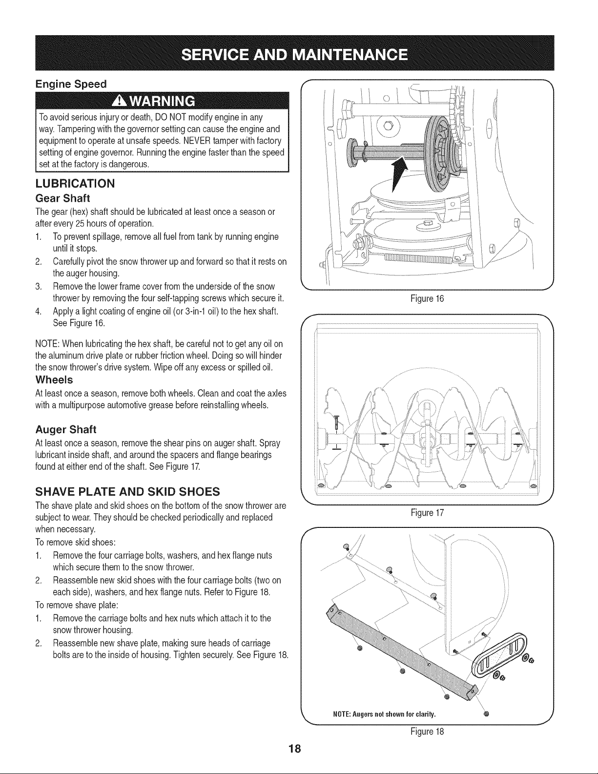
LUBRICATION
Gear Shaft
Thegear(hex)shaft shouldbe lubricatedat leastoncea seasonor
afterevery25 hoursof operation.
1. Topreventspillage,removeall fuel fromtank by runningengine
until it stops.
2. Carefullypivotthe snowthrowerupand forwardso that itrestson
theaugerhousing.
3. Removethe lowerframecoverfromthe undersideof the snow
throwerby removingthe four self-tappingscrewswhichsecureit.
4. Applya lightcoatingof engineoil (or3-in-1oil) to the hexshaft.
SeeFigure16.
NOTE:Whenlubricatingthe hexshaft,be carefulnotto get any oilon
thealuminumdriveplateor rubberfrictionwheel.Doingsowill hinder
the snowthrower'sdrive system.Wipeoff anyexcessor spilledoil.
Wheels
At leastoncea season,removebothwheels.Cleanandcoat theaxles
witha multipurposeautomotivegreasebeforereinstallingwheels.
Auger Shaft
At leastoncea season,removethe shearpinson augershaft.Spray
lubricantinsideshaft,andaroundthe spacersand flangebearings
foundat eitherend of the shaft. SeeFigure17.
SHAVE PLATE AND SKID SHOES
The shaveplateand skidshoesonthe bottomof the snowthrowerare
subjectto wear.Theyshouldbecheckedperiodicallyand replaced
whennecessary.
To removeskidshoes:
1. Removethe four carriagebolts,washers,andhex flangenuts
whichsecurethem to the snowthrower.
2. Reassemblenew skid shoeswiththe fourcarriagebolts (twoon
eachside),washers,and hex flangenuts.Referto Figure18.
To removeshaveplate:
1. Removethe carriageboltsand hexnutswhichattachit to the
snowthrowerhousing.
2. Reassemblenew shaveplate,makingsureheadsof carriage
boltsare to the insideof housing.Tightensecurely.See Figure18.
Figure16
f
/
Figure17
J
\\
\\
\\
Figure18
18
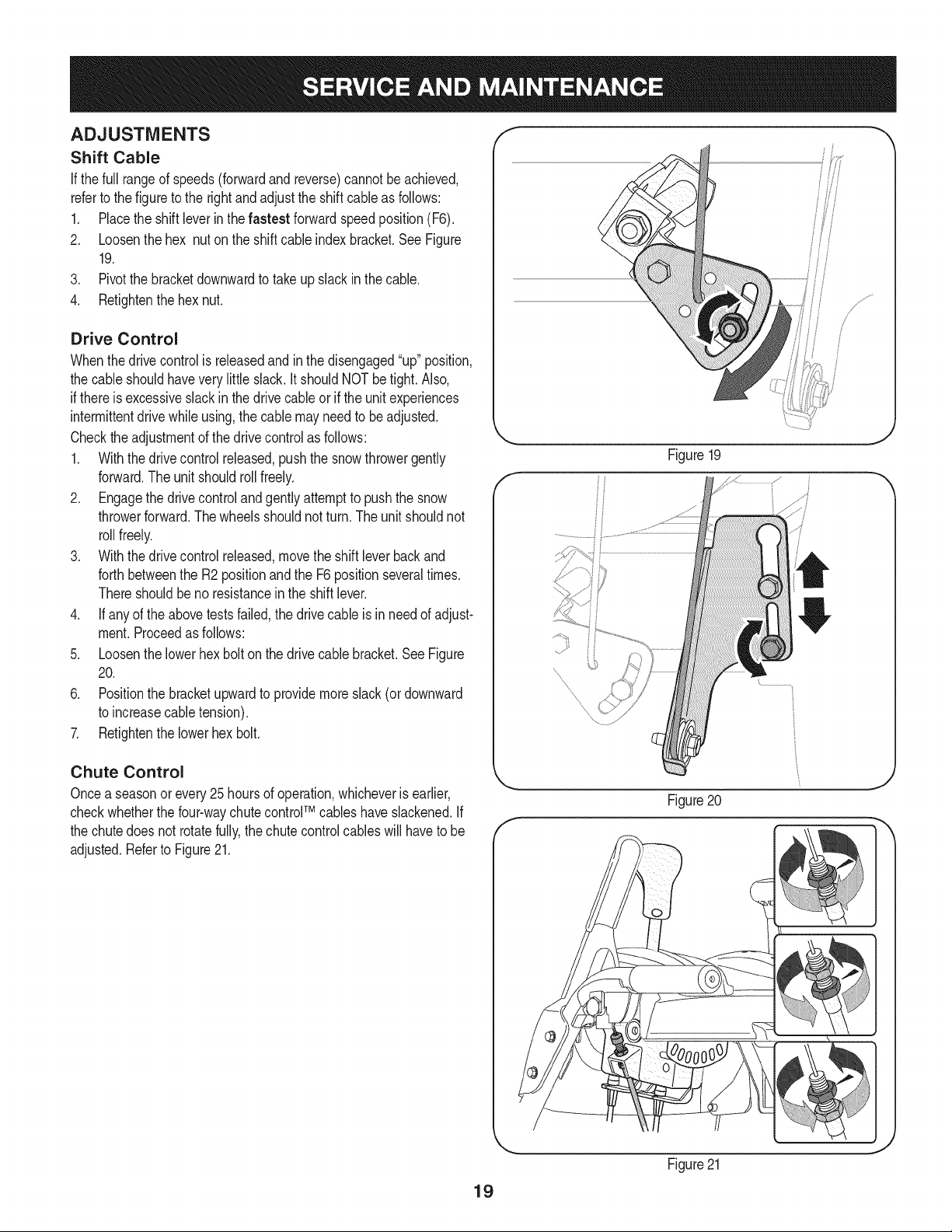
ADJUSTMENTS
Shift Cable
If thefull rangeof speeds(forwardand reverse)cannotbe achieved,
referto the figureto the rightand adjustthe shift cableas follows:
1. Placethe shiftleverin thefastest forward speedposition(F6).
2. Loosenthe hex nuton the shiftcable indexbracket.See Figure
19.
3. Pivotthe bracketdownwardto takeup slack in the cable.
4. Retightenthehex nut.
Drive Control
Whenthedrivecontrolis releasedandin thedisengaged"up"position,
the cableshouldhaveverylittle slack.It shouldNOTbetight. Also,
if thereis excessiveslackin thedrive cableor if the unitexperiences
intermittentdrivewhileusing,the cable mayneed to be adjusted.
Checktheadjustmentof the drivecontrolas follows:
1. Withthedrivecontrol released,pushthe snowthrowergently
forward.The unitshouldrollfreely.
2. Engagethe drivecontroland gentlyattemptto pushthe snow
throwerforward.Thewheelsshouldnotturn.The unitshouldnot
rollfreely.
3. With thedrivecontrolreleased,movethe shift leverbackand
forthbetweenthe R2positionand the F6 positionseveraltimes.
Thereshouldbeno resistancein the shiftlever.
4. If anyof the abovetests failed,the drivecable is in needof adjust-
ment.Proceedas follows:
5. Loosenthe lowerhexbolt on the drivecable bracket.See Figure
20.
6. Positionthe bracketupwardto providemoreslack(or downward
to increasecabletension).
7. Retightenthe lowerhex bolt.
Chute Control
Oncea seasonorevery 25hoursof operation,whicheveris earlier,
checkwhetherthe four-waychute controlTM cableshaveslackened.If
the chutedoes notrotatefully,the chutecontrolcables will haveto be
adjusted.Referto Figure21.
f
f
Figure20
Figure21
J
J
19
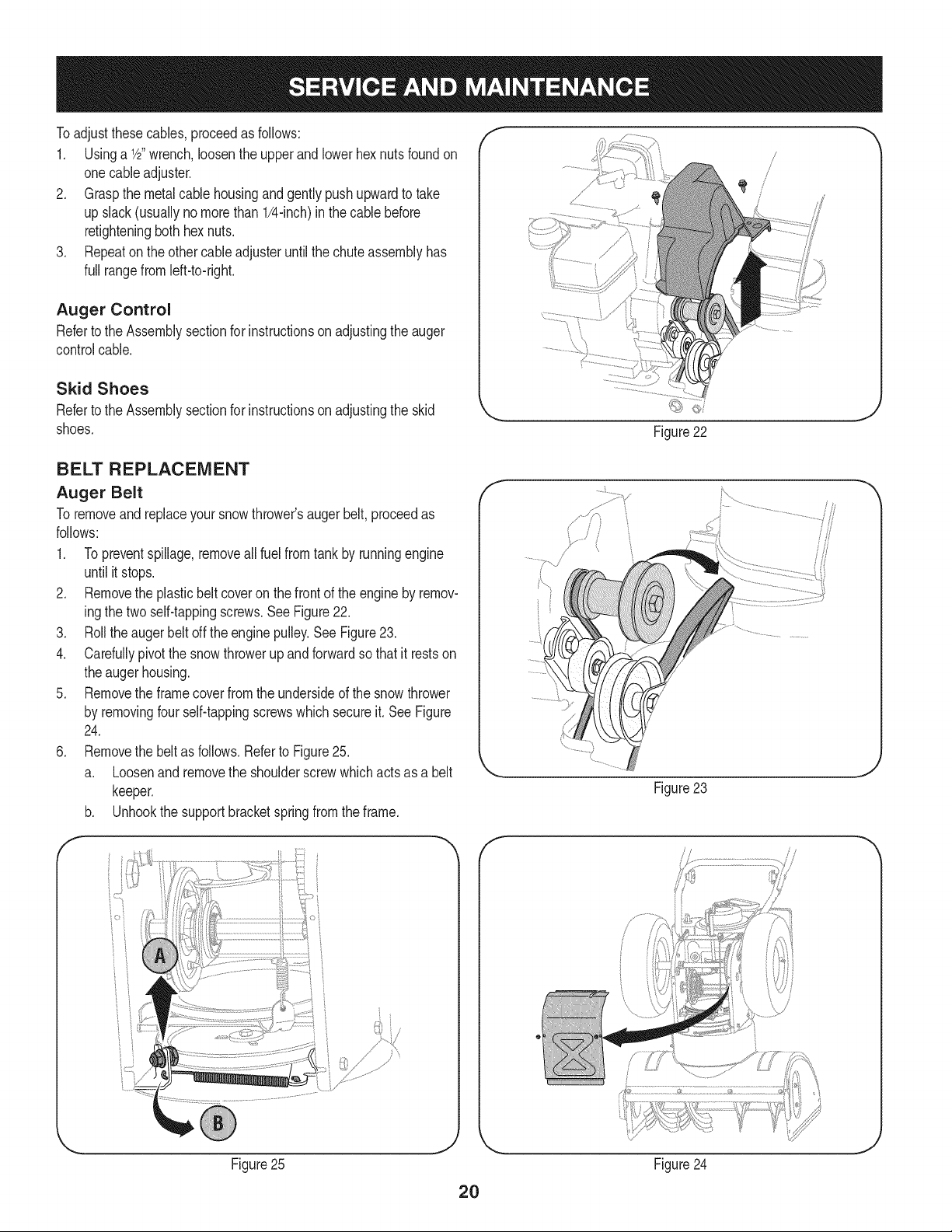
Toadjustthesecables,proceedas follows:
1. Usinga 1/2"wrench,loosenthe upperandlowerhexnutsfoundon
onecableadjuster.
2. Graspthe metalcablehousingandgentlypushupwardto take
up slack(usuallynomorethan 1/4-inch)in the cablebefore
retighteningboth hexnuts.
3. Repeaton the othercableadjusteruntilthe chuteassemblyhas
full rangefromleft-to-right.
Auger Control
Referto the Assemblysectionfor instructionsonadjustingtheauger
controlcable.
Skid Shoes
Referto the Assemblysectionfor instructionsonadjustingthe skid
shoes.
/
BELT REPLACEMENT
Auger Belt
To removeandreplaceyoursnowthrower'saugerbelt, proceedas
follows:
1. Topreventspillage,removeall fuel fromtank by runningengine
until itstops.
2. Removethe plasticbelt coveronthe frontof the engineby remov-
ingthe two self-tappingscrews.SeeFigure22.
3. Rollthe auger beltoff theenginepulley.See Figure23.
4. Carefullypivotthe snowthrowerupand forwardso that itrestson
theaugerhousing.
5. Removethe framecoverfrom the undersideof the snowthrower
by removingfourself-tappingscrewswhich secureit.SeeFigure
24.
6. Removethe beltas follows.Referto Figure25.
a. Loosenand removethe shoulderscrewwhich actsas a belt
keeper.
b. Unhookthe supportbracketspringfromthe frame.
f
Figure23
J
f _ f
Figure25 Figure24
J
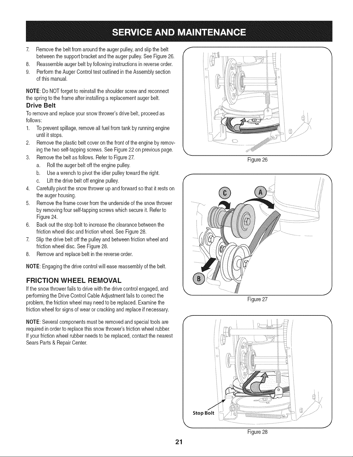
7. Removethebeltfromaroundtheaugerpulley,andslipthebelt
betweenthesupportbracketandtheaugerpulley.SeeFigure26.
8. Reassembleaugerbeltbyfollowinginstructionsinreverseorder.
9. PerformtheAugerControltestoutlinedintheAssemblysection
ofthismanual.
NOTE:DoNOTforgettoreinstalltheshoulderscrewandreconnect
thespringtotheframeafterinstallingareplacementaugerbelt.
Drive Belt
Toremoveand replaceyoursnowthrower'sdrivebelt,proceedas
follows:
1. Topreventspillage,removeallfuel fromtank by runningengine
untilit stops.
2. Removetheplasticbelt coveron the frontof the engineby remov-
ingthe two self-tappingscrews.See Figure22on previouspage.
3. Removethebelt as follows.Referto Figure27.
a. Rollthe auger beltoff theenginepulley.
b. Use awrenchto pivotthe idlerpulleytowardthe right.
c. Liftthe drivebelt off enginepulley.
4. Carefullypivotthe snowthrowerupand forwardsothat itrestson
the augerhousing.
5. Removetheframecoverfrom the undersideof the snowthrower
by removingfour self-tappingscrewswhich secureit.Referto
Figure24.
6. Back outthe stop bolt to increasethe clearancebetweenthe
frictionwheeldiscand frictionwheel.SeeFigure28.
7. Slipthe drivebelt off the pulleyand betweenfrictionwheeland
frictionwheeldisc.SeeFigure28.
8. Removeandreplacebelt in the reverseorder.
NOTE:Engagingthe drivecontrolwill easereassemblyof the belt.
FRICTION WHEEL REMOVAL
If the snowthrowerfailsto drivewith thedrivecontrolengaged,and
performingthe DriveControlCableAdjustmentfailsto correctthe
problem,the frictionwheelmayneedto be replaced.Examinethe
frictionwheelfor signsof wearor crackingandreplaceif necessary.
NOTE:Severalcomponentsmustbe removedandspecialtoolsare
requiredinorder to replacethis snowthrower'sfrictionwheelrubber.
If yourfrictionwheel rubberneedsto bereplaced,contact the nearest
SearsParts& RepairCenter.
ioi
Figure26
Figure27
.J
f
io i
i
Figure28
21
Ifthe snowthrowerwillnot be usedfor30 daysor longer,or if it is the end of the snowseasonwhenthe last possibilityof snowis gone,the
equipmentneedsto be storedproperly.Followstorageinstructionsbelowto ensuretop performancefromthe snowthrowerfor manymoreyears.
PREPARING ENGINE
Forenginesstoredover30days:
1. Topreventgum from forminginfuel systemor on essentialcarbure-
tor parts:
a. If fueltankcontainsoxygenatedor rdormulatedgasoline
(gasolineblendedwithan alcoholorether), runengineuntilit stops
fromlack of fuel.
Alcoholblendedfuels(calledgasoholor usingethanolor methanol)
canattractmoisturewhichleadsto separationand formationof acids
duringstorage.Acidicgas can damagethefuel systemof an engine
_wh e n storage.
b. If fueltankcontainsgasoline,eitherrunengineuntilit stopsfrom
lackof fuel or adda gasolineadditiveto the gas in the tank. If you
usea gas additive,runthe enginefor severalminutesto circulate
theadditivethroughthecarburetor.
Neverstoresnowthrowerwith fuel in tank indoorsor inpoorlyventi-
latedareas,wherefuel fumesmayreachan openflame,sparkor pilol
lightas ona furnace,waterheater,clothesdryer orgas appliance.
.
3.
Whiletheengineis still warm,changethe oil.
Removethe sparkplug andpourabout 1/2 ounceof engine oil
throughthe sparkplugholeinto the cylinder.Replacesparkplug
andcrankthe engineseveraltimesto distributethe oil.
PREPARING SNOW THROWER
• Whenstoringthe snowthrowerin an unventilatedor metalstor-
age shed,careshouldbetaken to rustprooftheequipment.Using
a light oilor silicone,coattheequipment,especiallyanychains,
springs,bearingsandcables.
• Removealldirt fromexteriorof engineand equipment.
• Followlubricationrecommendations.
• Storeequipmentin a clean,dry area.
Neveruseengineor carburetorcleaningproductsin the fueltank or
permanentdamagemayoccur.
22
Enginefailsto start
Enginerunserratically
Engineoverheats
Excessivevibration
Lossof power
Unitfails to propel itself
Unitfails to dischargesnow
1. Chokecontrolnot in ON position
2. Sparkplugwire disconnected
3. Faultysparkplug
4. Fueltank emptyorstalefuel
5. Enginenotprimed.
6. Safetykeynot inserted.
1. Enginerunningon CHOKE
2. Stalefuel
3. Wateror dirt in fuel system
4. Carburetorout of adjustment
1. Carburetornot adjustedproperly
1. Loosepartsor damagedauger
1. Sparkplugwire loose.
2. Gascap vent holeplugged.
1. Drivecable in needof adjustment
2. Drivebelt looseor damaged
3. Wornfrictionwheel.
1. Chuteassemblyclogged.
2. Foreignobjectlodgedin auger.
3. Augercablein needof adjustment.
4. Augerbelt looseor damaged.
5. Shearpin(s) sheared.
1. Movechokecontrolto ONposition.
2. Connectwireto sparkplug.
3. Clean,adjustgap,or replace.
4. Filltank withclean,freshgasoline.
5. Primeengineas instructedinthe OperationSection.
6. Insertkeyfully intothe switch.
1. Movechokecontrolto OFFposition.
2. Filltank withclean,freshgasoline.
3. Drainfueltank. Refillwith freshfuel.
4. ContactyourSearsParts& RepairCenter.
1. ContactyourSearsParts& RepairCenter.
1. Stopengineimmediatelyand disconnectsparkplug
wire.Tightenall boltsand nuts.Ifvibrationcontinues,
haveunitservicedbya SearsParts& RepairCenter.
1. Connectandtightenspark plugwire.
2. Removeice andsnow fromgascap. Becertainvent
holeis clear.
1. Adjustdrivecontrolcable. Referto Serviceand
Maintenancesection.
2. Replacedrive belt. Referto ServiceandMainte-
nancesection.
3. Changefrictionwheelor contactyour SearsParts&
RepairCenter.
1. Stopengineimmediatelyand disconnectsparkplug
wire.Cleanchuteassemblyandinsideof auger
housingwithclean-outtool or a stick.
2. Stopengineimmediatelyand disconnectsparkplug
wire.Removeobjectfromaugerwithclean-outtool
ora stick.
3. Adjustaugercontrolcable. Referto Assembly
section.
4. Replaceauger belt.Referto ServiceandMainte-
nancesection.
5. Replacewith new shearpin(s).
23
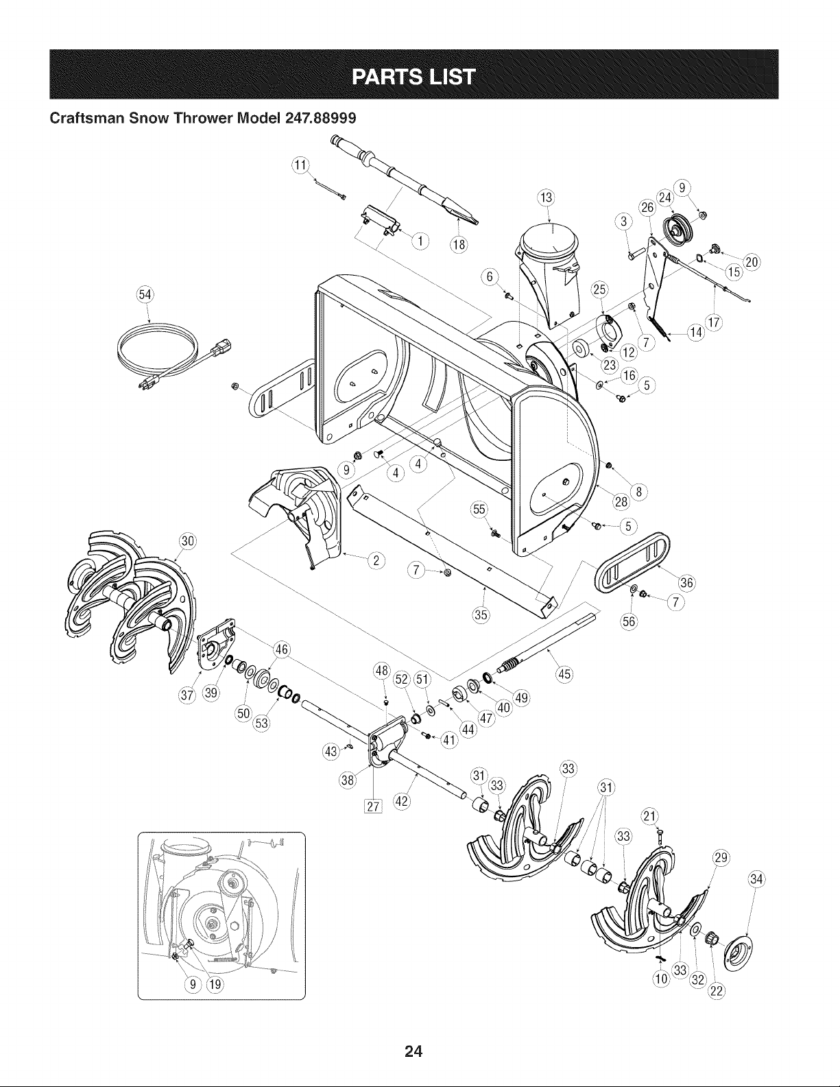
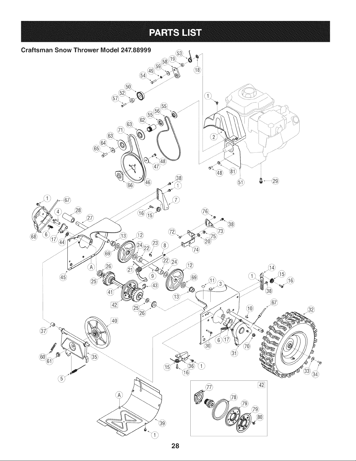
Craftsman Snow Thrower IViodel 247.88999
i
I
)
24
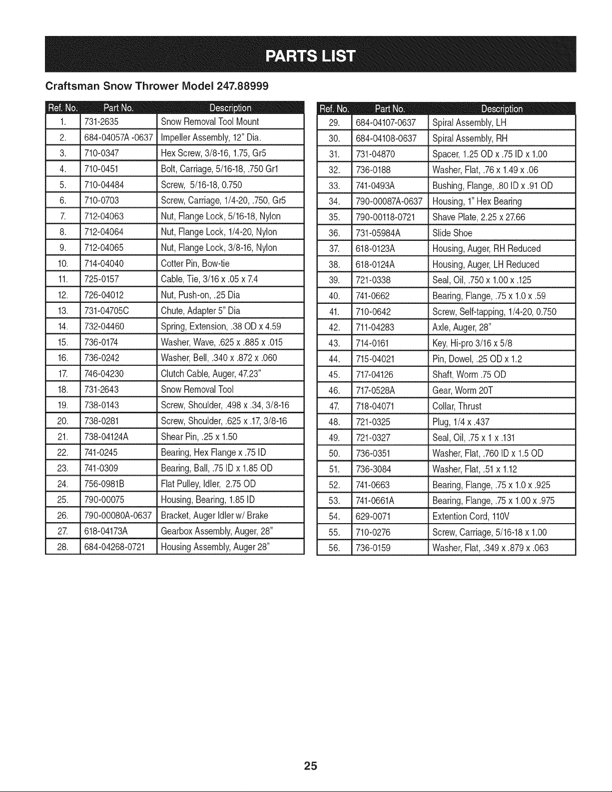
Craftsman Snow Thrower IViodel 247.88999
D = 0 0
731-2635 SnowRemovalToolMount
2. 684-04057A-0637 ImpellerAssembly,12"Dia.
3. L710-0347 LHex Screw,3/8-16, 1.75,Gr5
4. 710-0451 Bolt,Carriage,5/16-18,.750Grl
5. 710-04484 Screw, 5/16-18,0.750
6. 710-0703 Screw,Carriage,1/4-20,.750,Gr5
7. 712-04063 Nut, FlangeLock,5/16-18,Nylon
8. 712-04064 Nut, FlangeLock,1/4-20,Nylon
9. 712-04065 Nut, FlangeLock,3/8-16,Nylon
10. 714-04040 CotterPin,Bow-tie
11. 725-0157 Cable,Tie, 3/16x .05x 7.4
12. 726-04012 Nut, Push-on,.25 Dia
13. 731-04705C Chute,Adapter5" Dia
14. 732-04460 Spring,Extension,.38ODx 4.59
15. 736-0174 Washer,Wave,.625x .885x .015
16. 736-0242 Washer,Bell, .340x .872x .060
17. 746-04230 ClutchCable,Auger,47.23"
18. 731-2643 SnowRemovalTool
19. .738-0143 . Screw,Shoulder,.498x .34,3/8-16
20. 738-0281 Screw,Shoulder,.625x .17,3/8-16
21. 738-04124A ShearPin, .25x 1.50
22. 741-0245 Bearing,HexFlangex .75ID
23. 741-0309 Bearing,Ball,.75 IDx 1.85OD
24. 756-0981B FlatPulley,Idler, 2.75OD
25. 790-00075 Housing,Bearing,1.85ID
26. 790-00080A-0637 Bracket,Auger Idlerw/ Brake
27. J 618-04173A J GearboxAssembly,Auger,28"
28. 684-04268-0721 HousingAssembly,Auger28"
684-04107-0637
30. 684-04108-0637
31. 731-04870
32. 736-0188
33. 741-0493A
34. 790-00087A-0637
35. 790-00118-0721
36. 731-05984A
37. 618-0123A
38. 618-0124A
39. 721-0338
40. 741-0662
41. 710-0642
42. 711-04283
D = O O
SpiralAssembly,LH
SpiralAssembly,RH
Spacer,1.25OD x .75IDx 1.00
Washer,Flat,.76x 1.49x .06
Bushing,Flange,.80ID x .91OD
Housing,1"HexBearing
ShavePlate,2.25 x 27.66
SlideShoe
Housing,Auger,RH Reduced
Housing,Auger,LH Reduced
Seal,Oil, .750x 1.00x .125
Bearing,Flange,.75x 1.0x .59
Screw,Self-tapping,1/4-20,0.750
Axle,Auger,28"
43. 714-0161 Key,Hi-pro3/16x 5/8
44. 715-04021 Pin, Dowel,.25 ODx 1.2
45. 717-04126 Shaft,Worm.75OD
46. 717-0528A Gear,Worm20T
47. 718-04071 Collar,Thrust
48. 721-0325 Plug, 1/4x .437
49. 721-0327 Seal,Oil, .75x 1x .131
50. 736-0351 Washer,Flat,.760ID x 1.50D
51. 736-3084 Washer,Flat,.51x 1.12
52. 741-0663 Bearing,Flange,.75x 1.0x .925
53. 741-0661A Bearing,Flange,.75x 1.00x .975
54. 629-0071 ExtentionCord,110V
55. 710-0276 Screw,Carriage,5/16-18x 1.00
56. 736-0159 Washer,Flat,.349x .879x .063
25
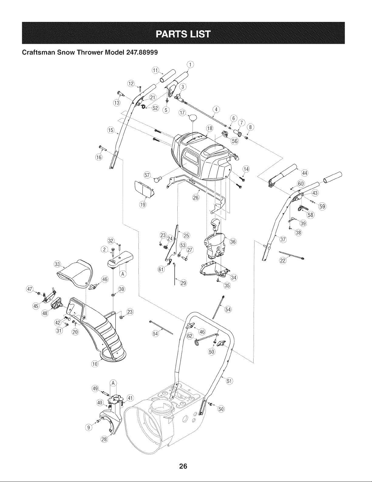
Craftsman Snow Thrower Model 247.88999
/
26
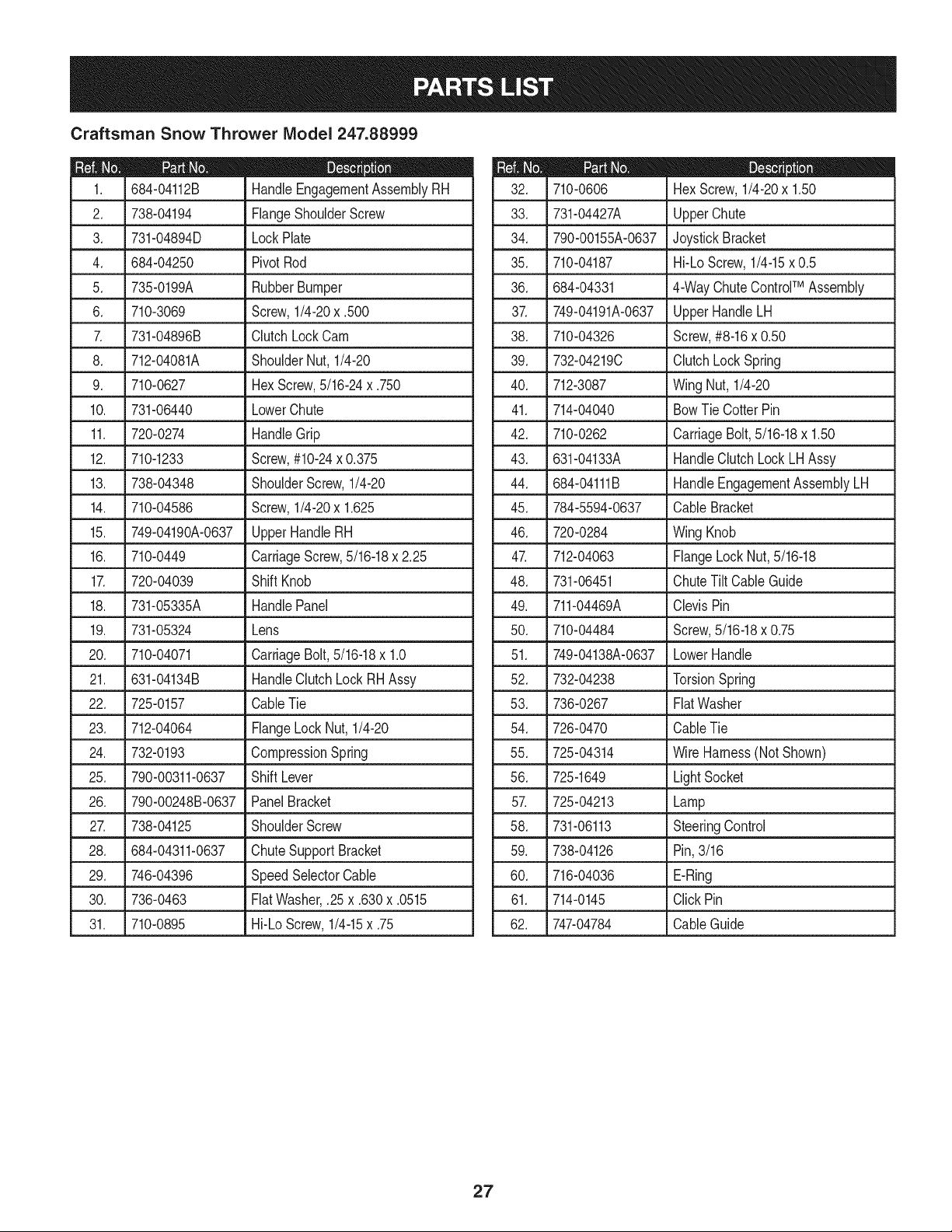
Craftsman Snow Thrower IViodel 247.88999
|= 0 =
684-04112B HandleEngagementAssemblyRH
2. 738-04194 FlangeShoulderScrew
3. 731-04894D LockPlate
4. 684-04250 PivotRod
5. 735-0199A RubberBumper
6. 710-3069 Screw,1/4-20x .500
7. 731-04896B ClutchLockCam
8. 712-04081A ShoulderNut, 1/4-20
9. 710-0627 HexScrew,5/16-24x .750
10. 731-06440 LowerChute
11. 720-0274 HandleGrip
12.
710-1233 Screw,#10-24x 0.375
13. 738-04348 ShoulderScrew,1/4-20
14. 710-04586 Screw,1/4-20x 1.625
15. 749-04190A-0637 UpperHandleRH
16. 710-0449 CarriageScrew,5/16-18x 2.25
17. 720-04039 ShiftKnob
18. 731-05335A HandlePanel
19. 731-05324 Lens
20. 710-04071 CarriageBolt,5/16-18x 1.0
21. 631-04134B HandleClutchLockRHAssy
22. 725-0157 CableTie
23. 712-04064 FlangeLock Nut, 1/4-20
24. 732-0193 CompressionSpring
25. 790-00311-0637 Shift Lever
26. 790-00248B-0637 PanelBracket
27. 738-04125 ShoulderScrew
28. 684-04311-0637 Chute SupportBracket
29. 746-04396 SpeedSelectorCable
30. 736-0463 FiatWasher,.25x .630x .0515
31. 710-0895 Hi-LoScrew,1/4-15x .75
D = O
710-0606 Hex Screw,1/4-20x 1.50
33. 731-04427A UpperChute
34. 790-00155A-0637 JoystickBracket
35. 710-04187 Hi-LoScrew,1/4-15x 0.5
36. 684-04331 4-WayChuteControlTM Assembly
37. 749-04191A-0637 UpperHandleLH
38. 710-04326 Screw,#8-16x 0.50
39. 732-04219C ClutchLockSpring
40. 712-3087 Wing Nut, 1/4-20
41. 714-04040 BowTie CotterPin
42. 710-0262 CarriageBolt,5/16-18x 1.50
43. 631-04133A HandleClutchLockLHAssy
44. 684-04111B HandleEngagementAssemblyLH
45. 784-5594-0637 Cable Bracket
46. 720-0284 Wing Knob
47. 712-04063 FlangeLockNut,5/16-18
48. 731-06451 ChuteTilt CableGuide
49. 711-04469A ClevisPin
50. 710-04484 Screw,5/16-18x 0.75
51. 749-04138A-0637 LowerHandle
52. 732-04238 TorsionSpring
53. 736-0267 FiatWasher
54. 726-0470 CableTie
55. 725-04314 Wire Harness(Not Shown)
56. 725-1649 LightSocket
57. 725-04213 Lamp
58. 731-06113 SteeringControl
59. 738-04126 Pin,3/16
60. 716-04036 E-Ring
61. 714-0145 Click Pin
62. 747-04784 CableGuide
27
Craftsman Snow Thrower Model 247.88999
i i
42_
40
28
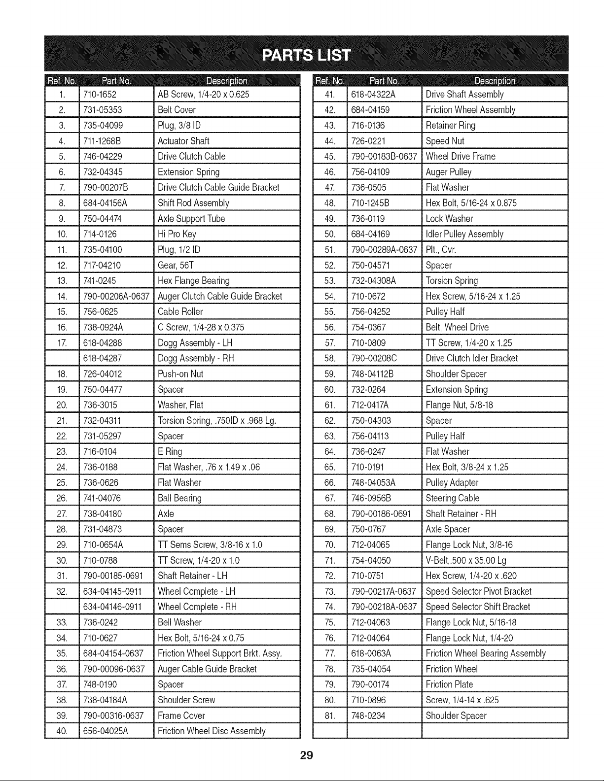
D_ i B O ¸
710-1652 AB Screw,1/4-20x 0.625
2. 731-05353 BeltCover
3. 735-04099 Plug,3/8 ID
4. 711-1268B ActuatorShaft
5. 746-04229 DriveClutchCable
6. 732-04345 ExtensionSpring
7. 790-00207B DriveClutchCableGuideBracket
8. 684-04156A ShiftRodAssembly
9. 750-04474 AxleSupportTube
10. 714-0126 Hi ProKey
11. 735-04100 Plug,1/2 ID
12. 717-04210 Gear,56T
13. 741-0245 HexFlangeBearing
14. 790-00206A-0637 AugerClutchCableGuideBracket
15. 756-0625 CableRoller
16. 738-0924A C Screw,1/4-28x 0.375
17. 618-04288 DoggAssembly-LH
618-04287 DoggAssembly- RH
18. 726-04012 Push-onNut
19. 750-04477 Spacer
20. 736-3015 Washer,Fiat
21. 732-04311 TorsionSpring,.7501Dx .968 Lg.
22. 731-05297 Spacer
23. 716-0104 E Ring
24. 736-0188 FiatWasher,.76x 1.49x .06
25. 736-0626 FiatWasher
26. 741-04076 BallBearing
27. 738-04180 Axle
28. 731-04873 Spacer
29. 710-0654A TT SeresScrew,3/8-16x 1.0
30. 710-0788 TT Screw,1/4-20x 1.0
31. 790-00185-0691 ShaftRetainer-LH
32. 634-04145-0911 WheelComplete-LH
634-04146-0911 WheelComplete-RH
33. 736-0242 BellWasher
34. 710-0627 HexBolt,5/16-24x 0.75
35. 684-04154-0637 FrictionWheelSupportBrkt.Assy.
36. 790-00096-0637 AugerCableGuideBracket
37. 748-0190 Spacer
38. 738-04184A ShoulderScrew
39. 790-00316-0637 FrameCover
40. 656-04025A FrictionWheelDiscAssembly
D _ O O
618-04322A DriveShaftAssembly
42. 684-04159 FrictionWheelAssembly
43. 716-0136 RetainerRing
44. 726-0221 SpeedNut
45. 790-00183B-0637 WheelDriveFrame
46. 756-04109 AugerPulley
47. 736-0505 FiatWasher
48. 710-1245B HexBolt,5/16-24x 0.875
49. 736-0119 LockWasher
50. 684-04169 IdlerPulleyAssembly
51. 790-00289A-0637 Pit.,Cvr.
52. 750-04571 Spacer
53. 732-04308A TorsionSpring
54. 710-0672 HexScrew,5/16-24x 1.25
55. 756-04252 PulleyHalf
56. 754-0367 Belt,WheelDrive
57. 710-0809 TT Screw,1/4-20x 1.25
58. 790-00208C DriveClutchIdlerBracket
59. 748-04112B ShoulderSpacer
60. 732-0264 ExtensionSpring
61. 712-0417A FlangeNut,5/8-18
62. 750-04303 Spacer
63. 756-04113 PulleyHalf
64. 736-0247 FiatWasher
65. 710-0191 HexBolt,3/8-24x 1.25
66. 748-04053A PulleyAdapter
67. 746-0956B SteeringCable
68. 790-00186-0691 ShaftRetainer- RH
69. 750-0767 Axle Spacer
70. 712-04065 FlangeLock Nut,3/8-16
71. 754-04050 V-Belt,.500x 35.00 Lg
72. 710-0751 HexScrew,1/4-20x .620
73. 790-00217A-0637 SpeedSelectorPivotBracket
74. 790-00218A-0637 SpeedSelectorShiftBracket
75. 712-04063 FlangeLock Nut,5/16-18
76. 712-04064 FlangeLock Nut, 1/4-20
77. 618-0063A FrictionWheelBearingAssembly
78. 735-04054 FrictionWheel
79. 790-00174 FrictionPlate
80. 710-0896 Screw,1/4-14x .625
81. 748-0234 ShoulderSpacer
29
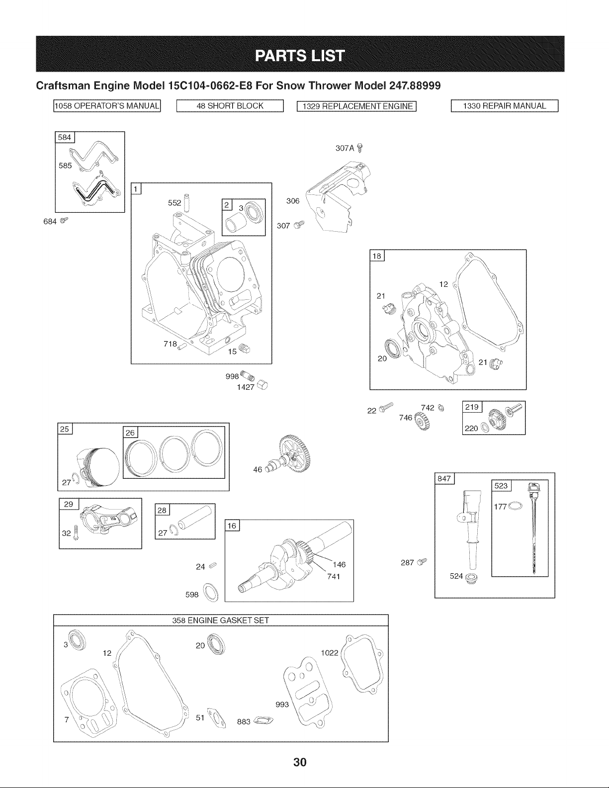
Craftsman Engine Model 15C104=0662=E8 For Snow Thrower Model 247.88999
11o58OPERATOR'SMANUALI [ 48 SHORT BLOCK I I 1329 REPLACEMENTENGINE I I 1330REPAIRMANUAL I
307A
684 _
q
552ii
718
24 0
598
146
741
21
22 _ 742 _9 1219 I ×_ ¢_1
220 '_
287 _f_
524 COb
II '-: y
358 ENGINE GASKET SET
12
2O
1O22
30
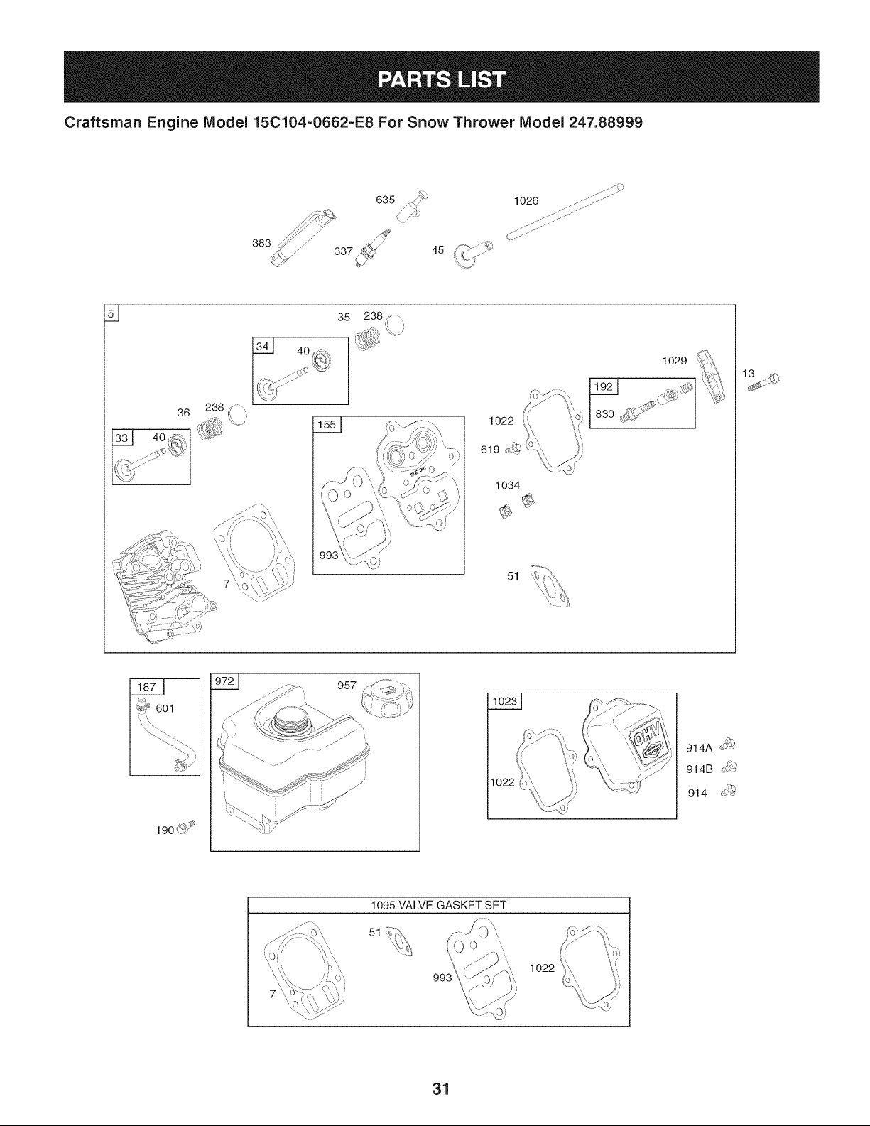
Craftsman Engine Model 15C104-0662-E8 For Snow Thrower Model 247.88999
\./
45
...._0
1026 .......(_[:
36
238
35 238
1034
1O29
....._ ',_;..... y_,
51
19o(_P
957
1022
914
1022
31
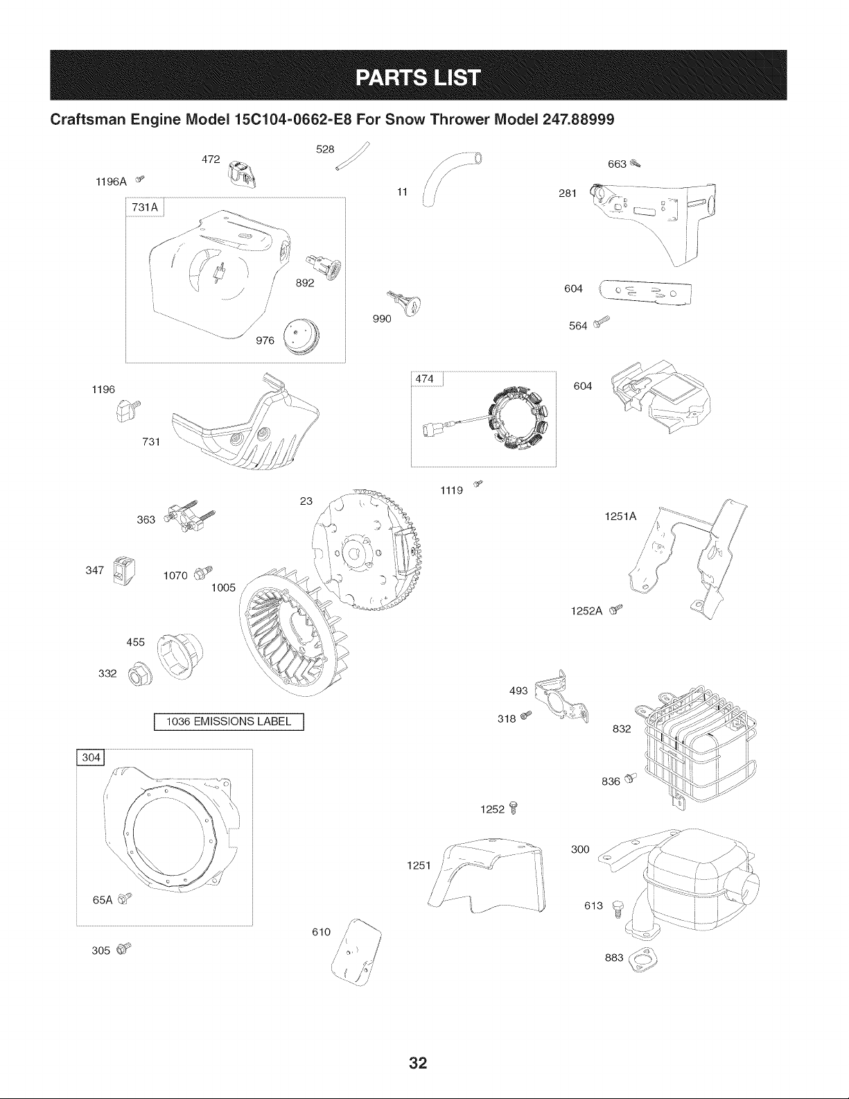
Craftsman Engine Model 15C104=0662=E8 For Snow Thrower Model 247.88999
528
472
1196A _
731A
........................ j_
.............. 976
990
11 , / 281
663_%
\
\
\
604 i( o _ :;_> o
564 (_
1196
347
332
'x
731 ""....
455
493
604
1252A (_
1251A
I 1036 EMISSIONS LABEL I
318 _-_
832
H
1252
836(_
65A_i _
305
/
610 ,'
300
613 _i_
883
32
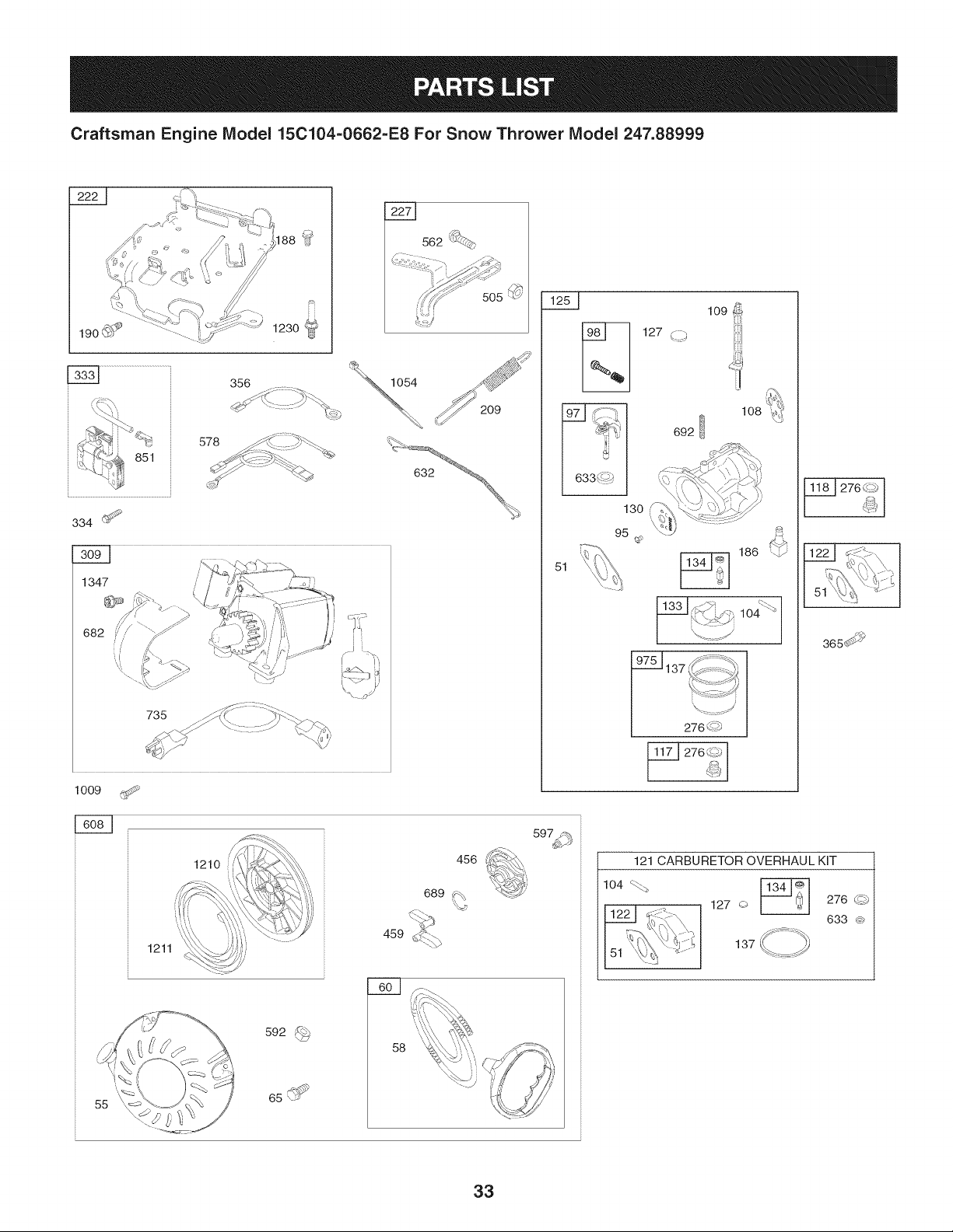
Craftsman Engine Model 15C104-0662=E8 For Snow Thrower Model 247.88999
562 "_4:_
851
578
209
334 GI"_
1347
735
1009
1211
1210
456
689 _%
459 d_:t_
51
55
592
65
58
3
130
95
127
108
692
276/_
18J 276 _b J
365_ _
121 CARBURETOR OVERHAUL KIT
104
127 o
137
276 dQ
633 @
33
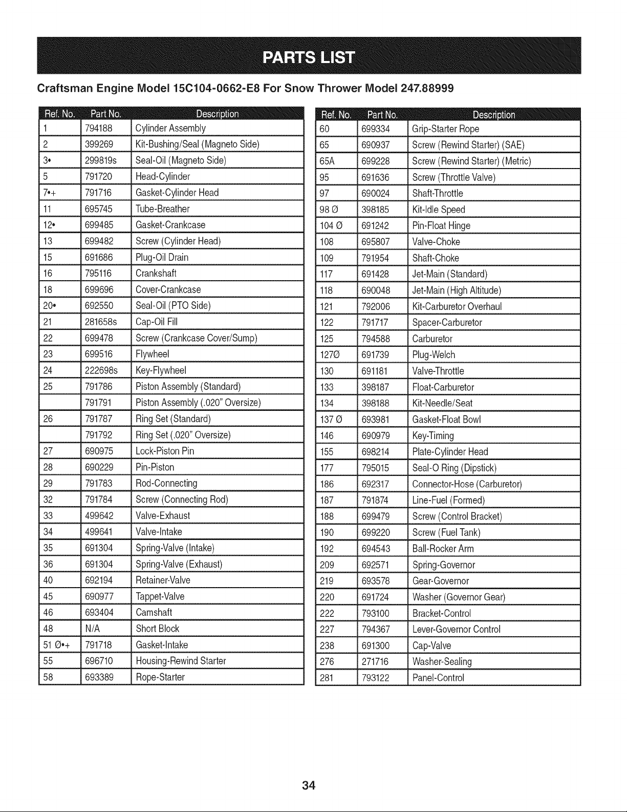
Craftsman Engine Model 15C104=0662=E8 For Snow Thrower Model 247.88999
D = O
794188 CylinderAssembly
2 399269 Kit-Bushing/Seal(MagnetoSide)
3o 299819s Seal-Oil(MagnetoSide)
5 791720 Head-Cylinder
7o+ 791716 Gasket-CylinderHead
11 695745 Tube-Breather
12o 699485 Gasket-Crankcase
13 699482 Screw(CylinderHead)
15 691686 Plug-OilDrain
16 795116 Crankshaft
18 699696 Cover-Crankcase
20, 692550 Seal-Oil(PTOSide)
21 281658s Cap-OilFill
22 699478 Screw(CrankcaseCover/Sump)
23 699516 Flywheel
24 222698s Key-Flywheel
25 791786 PistonAssembly(Standard)
• _ 791791 _PistonAssembly(.020"Oversize)
26 791787 RingSet (Standard)
791792 RingSet (.020"Oversize)
27 690975 Lock-PistonPin
28 690229 Pin-Piston
29 791783 Rod-Connecting
32 791784 Screw(ConnectingRod)
33 499642 Valve-Exhaust
34 499641 Valve-Intake
35 691304 Spring-Valve(Intake)
36 691304 Spring-Valve(Exhaust)
40 692194 Retainer-Valve
45 690977 Tappet-Valve
46 693404 Camshaft
48 N/A Short Block
51@,+ 791718 Gasket-intake
55 696710 Housing-RewindStarter
58 693389 Rope-Starter
699334 Grip-StarterRope
65 690937 Screw(RewindStarter)(SAE)
65A 699228 Screw(RewindStarter)(Metric)
95 691636 Screw(ThrottleValve)
97 690024 Shaft-Throttle
98 @ 398185 Kit-ldb Speed
104@ 691242 Pin-FloatHinge
108 695807 Valve-Choke
109 791954 Shaft-Choke
117 691428 Jet-Main(Standard)
118 690048 Jet-Main(HighAltitude)
121 792006 Kit-CarburetorOverhaul
122 791717 Spacer-Carburetor
125 794588 Carburetor
1270 691739 Plug-Webh
130 691181 Valve-Throttle
133 398187 Float-Carburetor
134 398188 Kit-Needle/Seat
137@ 693981 Gasket-FloatBowl
146 690979 Key-Timing
155 698214 Plate-CylinderHead
177 795015 Seal-O Ring(Dipstick)
186 692317 Connector-Hose(Carburetor)
187 791874 Line-Fuel(Formed)
188 699479 Screw(Control Bracket)
190 699220 Screw(FuelTank)
192 694543 Bali-RockerArm
209 692571 Spring-Governor
219 693578 Gear-Governor
220 691724 Washer(GovernorGear)
222 793100 Bracket-Control
227 794367 Lever-GovernorControl
238 691300 Cap-Valve
276 271716 Washer-Sealing
281 793122 Panel-Control
34
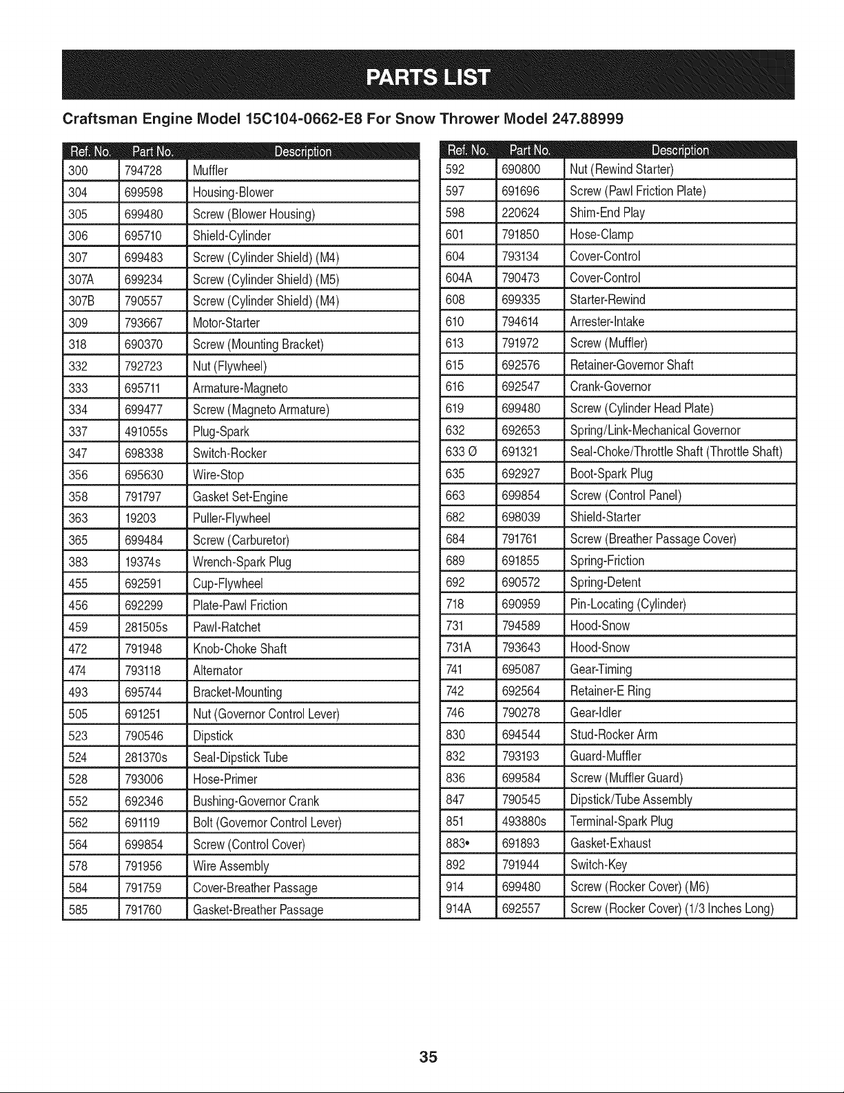
Craftsman Engine IViodel 15C104=0662=E8 For Snow Thrower IViodel 247.88999
D = O
794728 Muffler
304 699598 Housing-Blower
305 699480 Screw(BlowerHousing)
306 695710 Shield-Cylinder
307 699483 Screw(CylinderShield) (M4)
307A 699234 Screw(CylinderShield)(M5)
307B 790557 Screw(CylinderShield)(M4)
309 793667 Motor-Starter
318 690370 Screw(MountingBracket)
332 792723 Nut (Flywheel)
333 695711 Armature-Magneto
334 699477 Screw(MagnetoArmature)
337 491055s Plug-Spark
347 698338 Switch-Rocker
356 695630 Wire-Stop
358 791797 GasketSet-Engine
363 19203 Puller-Flywheel
365 699484 Screw(Carburetor)
383 19374s Wrench-SparkPlug
455 692591 Cup-Flywheel
456 692299 Plate-PawlFriction
459 281505s PawI-Ratchet
472 791948 Knob-ChokeShaft
474 793118 Alternator
493 695744 Bracket-Mounting
505 691251 Nut (GovernorControlLever)
523 790546 Dipstick
524 281370s Seal-DipstickTube
528 793006 Hose-Primer
552 692346 Bushing-GovernorCrank
562 691119 Bolt(GovernorControlLever)
564 699854 Screw(ControlCover)
578 791956 WireAssembly
584 791759 Cover-BreatherPassage
585 791760 Gasket-BreatherPassage
D = O O
690800 Nut (RewindStarter)
597 691696 Screw(PawlFrictionPlate)
598 220624 Shim-EndPlay
601 791850 Hose-Clamp
604 793134 Cover-Control
604A 790473 Cover-Control
608 699335
610 794614
613 791972
615 692576
616 692547
619 699480
632 692653
633 0 691321
Starter-Rewind
Arrester-lntake
Screw(Muffler)
Retainer-GovernorShaft
Crank-Governor
Screw(CylinderHeadPlate)
Spring/Link-MechanicalGovernor
Seal-Choke/ThrottleShaft(ThrottleShaft)
635 692927 Boot-SparkPlug
663 699854 Screw(Control Panel)
682 698039 Shield-Starter
684 791761 Screw(BreatherPassageCover)
689 691855 Spring-Friction
692 690572 Spring-Detent
718 690959 Pin-Locating(Cylinder)
731 794589 Hood-Snow
731A 793643 Hood-Snow
741 695087 Gear-Timing
742 692564 Retainer-ERing
746 790278 Gear-Idler
830 694544 Stud-RockerArm
832 793193 Guard-Muffler
836 699584 Screw(MufflerGuard)
847 790545 Dipstick/TubeAssembly
851 493880s Terminal-SparkPlug
883. 691893 Gasket-Exhaust
892 791944 Switch-Key
914 699480 Screw(RockerCover)(M6)
914A 692557 Screw(RockerCover)(1/3InchesLong)
35
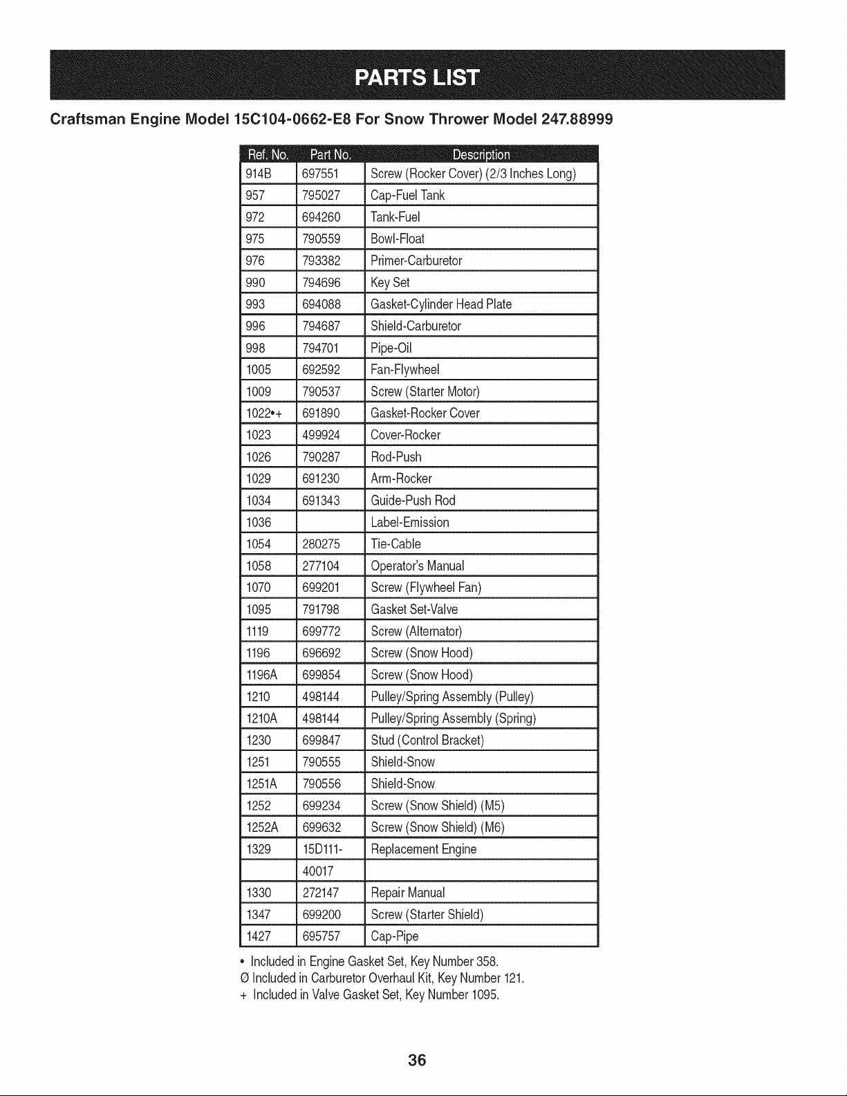
Craftsman Engine Model 15C104=0662=E8 For Snow Thrower Model 247.88999
D = O
697551 Screw(RockerCover)(2/3 InchesLong)
957 795027 Cap-FuelTank
972 694260 Tank-Fuel
975 790559 Bowl-Float
976 793382 Primer-Carburetor
990 794696 KeySet
993 694088 Gasket-CylinderHeadPlate
996 794687 Shield-Carburetor
998 794701 Pipe-Oil
1005 692592 Fan-Flywheel
1009 790537 Screw(StarterMotor)
1022++ 691890 Gasket-RockerCover
1023 499924 Cover-Rocker
1026 790287 Rod-Push
1029 691230 Arm-Rocker
1034 691343 Guide-PushRod
1036 Label-Emission
1054 280275 Tie-Cable
1058 277104 Operator'sManual
1070 699201 Screw(FlywheelFan)
1095 791798 GasketSet-Valve
1119 699772 Screw(Alternator)
1196 696692 Screw(SnowHood)
1196A 699854 Screw(SnowHood)
1210 498144 Pulley/SpringAssembly(Pulley)
1210A 498144 Pulley/SpringAssembly(Spring)
1230 699847 Stud(ControlBracket)
1251 790555 Shield-Snow
1251A 790556 Shield-Snow
1252 699234 Screw(SnowShield)(M5)
1252A 699632 Screw(SnowShield)(M6)
1329 15Dl11- ReplacementEngine
40017
1330 272147 RepairManual
1347 699200 Screw(StarterShield)
1427 695757 Cap-Pipe
+ Included
in EngineGasketSet,KeyNumber358.
0 Includedin CarburetorOverhaulKit, KeyNumber121.
+ IncludedinValveGasketSet,KeyNumber1095.
36
MTD CONSUMER GROUP INC (MTD), the California Air Resources Board (CARB)
and the United States Environment Protection Agency (U. S. EPA)
Emission Control System Warranty Statement
(Owner's Defect Warranty Rights and Obligations)
EMISSIONCONTROLSYSTEMCOVERAGEIS APPLICABLETOCERTIFIEDENGINESPURCHASEDIN CALIFORNIAIN2005 ANDTHERE-
AFTER,WHICHARE USEDIN CALIFORNIA,ANDTO CERTIFIEDMODELYEAR2005AND LATERENGINESWHICHARE PURCHASEDAND
USEDELSEWHEREIN THEUNITEDSTATES.
Californiaandelsewherein the UnitedStatesEmissionControlDefectsWarrantyCoverage
The CaliforniaAir ResourcesBoard(CARB),U.S. EPAand MTDarepleasedto explaintheemissionscontrol systemwarrantyon your modelyear
2006and latersmalloff-roadengine.In California,new smalloff-roadenginesmustbe designed,builtand equippedto meettheStatesanti-smog
standards.Elsewhereinthe UnitedStates,newnon-road,spark-ignitionenginescertifiedfor model2005and later,mustmeetsimilarstandardsset
forthby the U. S. EPA.MTDmustwarrantythe emissioncontrolsystemonyourenginefor the periodof timelistedbelow,providedtherehasbeen
noabuse,neglector impropermaintenanceof your smalloff-roadengine.
Youremissioncontrolsystemmay includepartssuchas the carburetor,fuel-injectionsystem,the ignitionsystem,andcatalyticconverter,fuel
tanks,fuel lines,fuel caps,valves,canisters,filters,vaporhoses,clamps,connectors,andotherassociatedemission-relatedcomponents.
Wherea warrantableconditionexists,MTDwill repairyoursmalloff-roadengineat no cost to yourincludingdiagnosis,partsand labor.
MANUFACTURER'S WARRANTY COVERAGE:
Thisemissionscontrolsystemis warrantedfor twoyears.If anyemission-relatedpart on yourengineis defective,the part will be repairedor
replacedby MTD.
OWNER'S WARRANTY RESPONSIBILITIES:
As the smalloff-roadengineowner,youare responsibleforthe performanceof the requiredmaintenancelisted inyour Owner'sManual.MTD
recommendsthatyou retainall yourreceiptscoveringmaintenanceson yoursmalloff-roadengine,but MTDcan not denywarrantysolelyfor the
lackof receiptsor foryour failureto ensurethe performanceto allscheduledmaintenance.
As the smalloff-roadengineowner,youshouldhoweverbeawarethat MTDmaydenyyour warrantycoverageif yoursmalloff-roadengine orpart
hasfaileddue toabuse,neglect,impropermaintenanceor unapprovedmodifications.
Youare responsiblefor presentingyour smalloff-roadengineto an AuthorizedMTDServiceDealeras soonas a problemexists.Thewarranted
repairsshouldbe completedina reasonableamountof time,notto exceed30 days.
Ifyou haveanyquestionsregardingyourwarrantyrightsand responsibilities,you shouldcontacta MTDService Representativeat 1-800-800-7310
andaddressis MTDCONSUMERGROUP,RO. Box361131,ClevelandOH,44136-0019.
DEFECTS WARRANTY REQUIREMENTS FOR 1995 AND LATER SMALL OFF-ROAD ENGINES:
Thissectionappliesto 1995andlater smalloff-roadengines.The warrantyperiodbeginsonthe datethe engineor equipmentis deliveredto an
ultimatepurchaser.
(a) GeneralEmissionsWarrantyCoverage
MTDmustwarrantto the ultimatepurchaserandeachsubsequentpurchaserthatthe engineis:
(1)Designed,built,andequippedsoas to conformwithall applicableregulationsadoptedby the Air ResourcesBoardpursuantto its authorityin
Chapters1and2,Part5, Division26of the HealthandSafetyCode;and
(2) Freefrom defectsin materialsandworkmanshipthat causethe failureof a warrantedpart to beidenticalin all materialrespectsto the partas
describedin theenginemanufacturer'sapplicationfor certificationfora periodof twoyears.
(b)The warrantyonemissions-relatedpartswill be interpretedas follows:
(1)Anywarrantedpart that is not scheduledfor replacementas requiredmaintenancein the writteninstructionsrequiredby Subsection(c)
mustbewarrantedfor the warrantyperioddefinedinSubsection(a)(2). Ifany such partfailsduringthe periodof warrantycoverage,it mustbe
repairedor replacedby MTDaccordingto Subsection(4)below.Anysuchpart repairedor replacedunder thewarrantymustbewarrantedfor
the remainingwarrantyperiod.
(2)Any warrantedpartthat is scheduledonlyfor regularinspectioninthe writteninstructionsrequiredby Subsection(c) must be warrantedfor
thewarrantyperioddefinedin Subsection(a)(2).A statementin suchwritteninstructionsto the effectof "repairor replaceas necessary"will
not reducethe periodof warrantycoverage.Anysuchpart repairedor replacedunderwarrantymustbe warrantedforthe remainingwarranty
period.
(3) Anywarrantedpartthat whichis scheduledfor replacementas requiredmaintenancein the writteninstructionsrequiredby Subsection(c)
mustbewarrantedfor the periodof time priorto the first scheduledreplacementpointforthat part.Ifthe part failspriorto thefirst scheduled
replacement,the part mustbe repairedor replacedby MTDaccordingto Subsection(4) below.Any suchpart repairedor replacedunder
warrantymustbewarrantedfor the remainderof the periodpriorto the first scheduledreplacementpointfor the part.
(4)Repairorreplacementofanywarrantedpartunderthewarrantyprovisionsofthisarticlemustbeperformedatnochargetotheownerata
warrantystation.
(5)NotwithstandingtheprovisionsofSubsection(4)above,warrantyservicesorrepairsmustbeprovidedatallMTDdistributioncentersthat
arefranchisedtoservicethesubjectengines.
(6)Theownermustnotbechargedfordiagnosticlaborthatleadstothedeterminationthatawarrantedpartisinfactdefective,providedthat
suchdiagnosticworkisperformedatawarrantystation.
(7)Theenginemanufacturerisliablefordamagestootherenginecomponentsproximatelycausedbyafailureunderwarrantyofanywarranted
part.
(8)Throughouttheengine'swarrantyperioddefinedinSubsection(a)(2),MTDwillmaintaina supplyofwarrantedpartssufficienttomeetthe
expecteddemandforsuchparts.
(9)Anyreplacementpartmaybeusedintheperformanceofanywarrantymaintenanceorrepairsandmustbeprovidedwithoutchargetothe
owner.SuchusewillnotreducethewarrantyobligationsofMTD.
(10)Add-onormodifiedpartsthatarenotexemptedbytheAirResourcesBoardmaynotbeused.Theuseofanynon-exemptedadd-onor
modifiedpartsshallbegroundsfordisallowingawarrantyclaimmadeinaccordancewiththisarticle.Theenginemanufacturershallnotbe
liableunderthisarticletowarrantfailuresofwarrantedpartscausedbytheuseofnon-exemptedadd-onormodifiedpart.
(c) MTDwill includea copyof the followingemissionwarrantypartslistwitheach newengine,usingthoseportionsof the list applicableto the
e__&gine.
(1)FuelMeteringSystem
• Coldstart enrichmentsystem(soft choke)
,,Carburetorandinternalparts
• Fuel Pump
• FuelTank
(2)Air InductionSystem
• Aircleaner
• Intakemanifold
(3) IgnitionSystem
• Sparkplug(s)
• MagnetoIgnitionSystem
(4)ExhaustSystem
Catalyticconverter
• SAI (Reedvalve)
(5) MiscellaneousItemsUsedin AboveSystem
Vacuum,temperature, position,timesensitivevalvesand switches
Connectorsandassemblies
(6) Evaporativecontrol
• Fuel Hosecertifiedfor ARBevaporativeemissionof 2006.
• Fuel HoseClamps
Tetheredfuel cap
Carboncanister
Vaporlines
GD0C-100174Rev.B
Look For Relevant Emissions Durability Period and
Air index information On Your Engine Emissions Label
Engines that are certified to meet the California Air Resources Board (CARB) Tier 2 Emission Standards must
display information regarding the Emissions Durability Period and the Air Index. Sears, Roebuck and Co., U.S.A.
makes this information available to the consumer on our emission labels.
The Emissions Durability Period describes the number of hours of actual running time for which the engine is
certified to be emissions compliant, assuming proper maintenance in accordance with the Operating & Mainte-
nance Instructions. The following categories are used:
Moderate: Engine is certified to be emission compliant for 125 hours of actual engine running time.
Intermediate: Engine is certified to be emission compliant for 250 hours of actual engine running time.
Extended: Engine is certified to be emission compliant for 500 hours of actual engine running time.
For example, a typical walk-behind lawn mower is used 20 to 25 hours per year. Therefore, the Emissions
Durability Period of an engine with an intermediate rating would equate to 10 to 12 years.
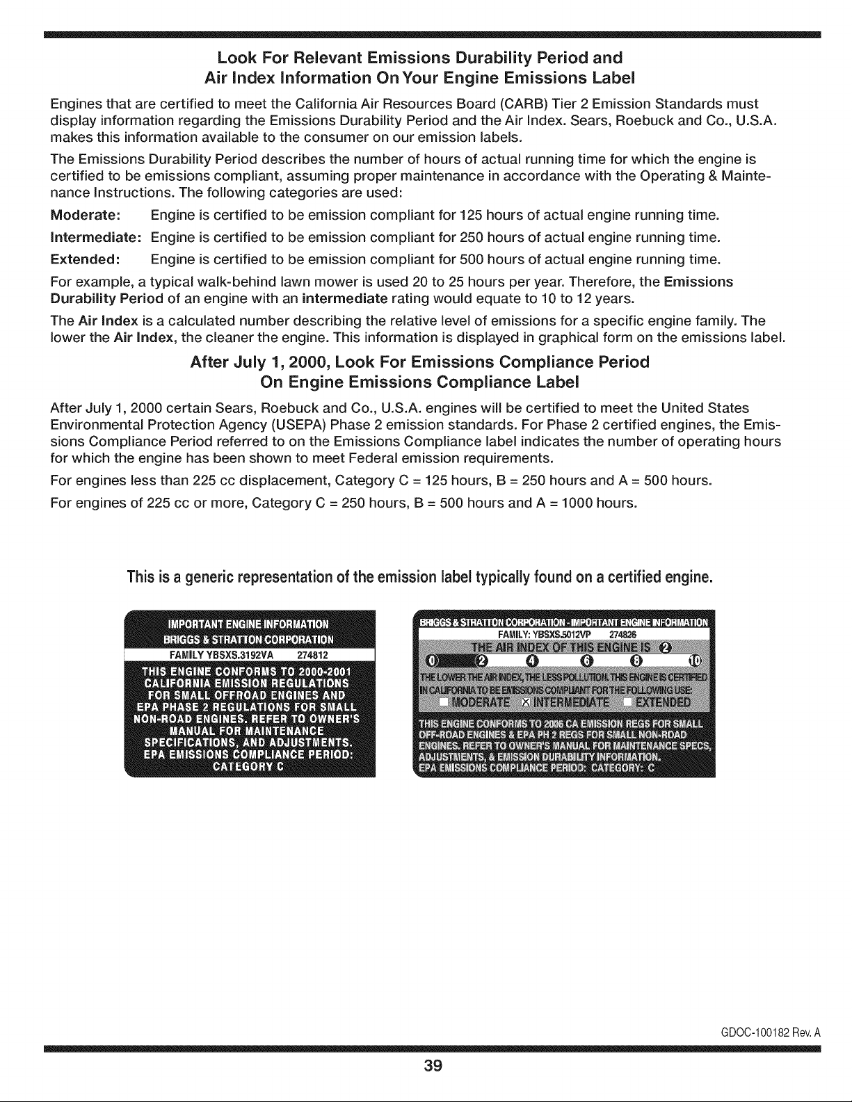
The Air Index is a calculated number describing the relative level of emissions for a specific engine family. The
lower the Air Index, the cleaner the engine. This information is displayed in graphical form on the emissions label.
After July 1,2000, Look For Emissions Compliance Period
On Engine Emissions Compliance Label
After July 1, 2000 certain Sears, Roebuck and Co., U.S.A. engines will be certified to meet the United States
Environmental Protection Agency (USEPA) Phase 2 emission standards. For Phase 2 certified engines, the Emis-
sions Compliance Period referred to on the Emissions Compliance label indicates the number of operating hours
for which the engine has been shown to meet Federal emission requirements.
For engines less than 225 cc displacement, Category C = 125 hours, B = 250 hours and A = 500 hours.
For engines of 225 cc or more, Category C = 250 hours, B = 500 hours and A = 1000 hours.
This is a generic representation of the emission label typically found on a certified engine.
FAMILYYBSXS.3192VA 274812
GDOC-100182Rev.A
39
Congratulationsonmakingasmartpurchase.YournewCraftsman@
productisdesignedandmanufacturedforyearsofdependableopera-
tion.Butlikeallproducts,itmayrequirerepairfromtimetotime.That's
whenhavingaRepairProtectionAgreementcansaveyoumoneyand
aggravation.
Here'swhattheRepairProtectionAgreement*includes:
* Expertservicebyour10,000professionalrepairspecialists
o Unlimitedserviceand no chargefor partsand laboron all
coveredrepairs
o Product replacementupto $1500if yourcoveredproductcan't be
fixed
• Discountof 10%from regularprice of serviceand relatedinstalled
partsnotcoveredby theagreement;also, 10%off regularpriceof
preventivemaintenancecheck
• Fast help by phone- we call it RapidResolution- phone support
froma Searsrepresentative.Thinkof usas a "talkingowner's
manual."
Onceyou purchasethe Agreement,a simplephonecall is all that it
takesfor youto scheduleservice.Youcan call anytimedayor night,or
schedulea serviceappointmentonline.
The RepairProtectionAgreementis a risk-freepurchase.If youcancel
for any reasonduringthe productwarrantyperiod,wewill providea full
refund.Or,a proratedrefundanytimeafterthe productwarrantyperiod
expires.Purchaseyour RepairProtectionAgreementtoday!
Somelimitationsand exclusionsapply. For pricesand additional
informationin the U.S.A. call 1-800-827-6655.
*Coverage inCanadavaries on some items. Forfull details call
Sears Canadaat 1-800-361-6665.
Sears Installation Service
ForSearsprofessionalinstallationof homeappliances,garagedoor
openers,waterheaters,andothermajorhomeitems,in the U.S.A.or
Canadacall 1-800-4-MY-HOME®.
4O
Declaraci6n de garantia ............................ Pagina 41
Practicas operaci6n seguras ..................... Pagina 42
Montaje ...................................................... Pagina 46
Operaci6n .................................................. Pagina 50
Servicio y Mantenimiento .......................... Pagina 54
Almacenamiento fuera de temporada ....... Pagina 61
Soluci6n de problemas .............................. Pagina 62
Acuerdo de protecci6n para reparaciones .... Pagina 67
Etiquetas de seguridad .............................. Pagina 7
Lista de piezas ........................................... Pagina 24
NOmero de servicio ................................... Cubierta
posterior
GARANTiA LIMITADA CRAFTSMAN
Dos Ahos en Lanzador de Nieve
Cuandohechofuncionary mantenidosegQntodasias instruccionessuministradas,si esteianzadorde nievefailadebidoa un defectoen mate-
rialo habilidaddentrode dos a_osde la fechao compra,Ilame 1-800-4MYHOMEhacerlos arreglospara reparaci6nlibre.
Estagarantias6iotendr_,vaiidezdurante90dias si este productose utilizaen cuaiquiermomentoparafinescomerciaieso de aiquiler.
Duranteel primeraSode lacompra,nohabr_,ningOnprecioparael serviciode garantiaensu casa. Parasu conveniencia,en decasael servicio
de garantiatodaviaestar_,disponibledespu_sdelprimeraSode la compra,peroun preciode viaje seaplicar& Esteprecioser_.renunciado
si ustedtransportaai ianzadorde nievea unaposici6nde bajadadeArtesanoautorizada.Parala posici6nautorizadam_.scercana,Ilame
1-800-4-MY-HOME®.
Estagarantia cubreSOLOdefectos en materialy habilidad.Sears no pagar_para:
• Losarticuiosprescindibiesquese haceniievadospuestosduranteei usonormal,inciuso,perono iimitadosparapatinarzapatos,platode
afeitado,esquilanalfileres,bujia,filtrode aire,cinturones,y fiitro delaceite.
• Revisi6nde mantenimientoest_ndar,cambiosde aceite,opuestasa punto.
• Reemplazode neum_ticoo reparaci6ncausadaporpinchazosdesdefueradeobjetos,como u_as,espinas,tocones,o cristal.
• Neum_ticoo reemplazode ruedao reparaci6nque resultade ropanormal,accidente,u operaci6nimpropiao mantenimiento.
• Lasreparacionesnecesariasdebidoal abusode operador,inclusoperonolimitadoparada_arcausadoafectandoobjetosque doblanel
marcoo el cigOe_al,oel sobreexcesode veiocidaddelmotor.
• Reparacionesnecesariasdebidoa negligenciadel operador,induyendoentreotros,da_osmec_nicoy eBctricoocasionadoporun
almacenamientono apropiado,fallapor el uso de aceitedegradoy/o cantidadnoapropiadaofalla por nodar mantenimientoalequipode
acuerdocon las instruccionescontenidasen elmanualdel operador.
• Limpiezao reparacionesal motor(sistemade combustible)provocadasporun combustiblecontaminadou oxidado(viejo). Engeneral,ei
combustibledebeutiiizarseen un periodonomayorde 30 dias a partirde su adquisici6n.
• El empejoramientonormaly la ropa delos fines exteriores,o productoetiquetanel reemplazo.
Estagarantias61otendr_,validezmientrasel productose utilice enlos EstadosUnidos.
Estagarantiale otorgaderechoslegaiesespedficos, perousted podriagozardeotrosderechosen raz6nde su lugarde residencia.
Sears,Roebuck and Co., Hoffman Estates, iL 60179
Tipode aceitedelmotor:
Capacidaddeaceitedel motor:
Capacidaddecombustible:
Bujfas:
Separaci6nde lasbujias:
SAE 5W-30
20 onzas
3 cuartos
Champion® RC12YC
.030"
NSrnerode modelo ..........................................................
N_merode serie ..............................................................
Fechade compra .............................................................
Registrearriba elnOmerodel modelo,elnOmerode seriey lafecha
decompra
© SearsBrands,LLC
41
Lapresenciade este sirnboloindicaque setrata de instrucciones
irnportantesde seguridadquese deben respetarpara evitar
ponerenpeligrosu seguridadpersonaly/o materialy lade otras
personas.Lea y sigatodaslasinstruccionesdeestemanualantes
de poneren funcionarnientoesta rn_.quina.Si no respetaestas
instruccionespodria provocarlesionespersonales.Cuandoveaeste
sirnbolo,ipresteatenci6na la advertencia!
PROPOSICI6N 65 DE CALIFORNIA
Elescapedel motorde este producto,algunosdesuscornponentes
y algunoscornponentesdel vehiculocontieneno liberansustancias
quirnicasqueel estadode Californiaconsideraque puedenproducir
c_.ncer,defectosde nacirnientouotros problernasreproductivos.
Estarn_.quinarueconstruidaparaseroperadadeacuerdocon
las reglasde seguridadcontenidaseneste manual.AI igualque
concualquiertipo deequipornotorizado,un descuidoo errorpor
partedeloperadorpuedeproducirlesionesgraves.Estarn_.quina
es capazde arnputarrnanosy piesy de arrojarobjetoscon gran
fuerza.De no respetarlas instruccionesde seguridadsiguientesse
puedenproducirlesionesgraveso la rnuerte.
Su responsabilidad--Restrinja el usode estarn_.quina
rnotorizadaalas personasque lean,cornprendany respetenlas
advertenciase instruccionesque apareceneneste manualyen la
rn_.quina.
iGUARDEESTASINSTRUCCIONES!
CAPACITACION
• Lea,entienday curnplatodaslas instruccionesincluidasen
la rn_.quinayen los rnanualesantesde rnontarlay utilizarla.
Guardeestemanualenun lugarseguropara consultasfuturasy
peri6dicas,asi cornopara solicitarrepuestos.
• Leael ManualdelOperadory sigatodas las advertenciase
instruccionesde seguridad.El fracasode hacerasi puedecausar
la heridaseriaal operadory/o personaspresentes.Para Ilarnada
de preguntas,1-800-659-5917.
• Farniliaricesecontodos los controlesy con el usoadecuado
de losrnisrnos.Sepa c6rnodetenerlarn_.quinay desactivarlos
controlesr_.pidarnente.
• No perrnitanuncaque losni_os rnenoresde 14a_osutilicen
estarn_.quina.Los ni_osde 14a_osenadelantedebenleer y
entenderlas instruccionesde operaci6ny norrnasde seguridad
contenidasen este manual,yen la rn_.quinaydebenserentrena-
dosy supervisadospor unadulto.
• Nuncaperrnitaquelos adultosoperenestarn_.quinasin recibir
antesla instrucci6napropiada.
• Losobjetosarrojadosporla rn_.quinapuedenproducirlesiones
graves.Planifiqueel patr6nenel queva air arrojandonievepara
evitarquela descargade materialse realicehacialos carninos,
los observadores,etc.
• Mantengaa los observadores,ayudantes,rnascotasy ni_ospor
Io rnenosa 75piesde larn_.quinarnientrasla rnisrnaest,.en
funcionarniento.Detengala rn_.quinasialguien se acerca.
• Seaprecavidopara evitarpatinarseo caerseespecialrnente
cuandooperala rn_.quinaen reversa.
PREPARATIVOS
Inspeccionerninuciosarnenteel _.readondeutilizar_,el equipo.Saque
todoslos felpudos,peri6dicos,trineos,tablas,cablesy otrosobjetos
extra_oscon los quepodriatropezaro quepodrianser arrojadospor
la barrena/ irnpulsor.
• Paraprotegerselosojos utilice siernpreanteojoso antiparras
de seguridadrnientrasoperala rn_.quinao rnientrasla ajusta
o repara.Losobjetosarrojadosque rebotanpuedenproducir
lesionesocularesgraves.
• Noopere larn_.quinasin la vestirnentaadecuadaparaestaral
aire libreen invierno.No utilicealhajas,bufandaslargasu otras
prendassueltasquepodrianenredarseenlas partesrn6viles.
Utiliceun calzadoespecialparasuperficiesresbaladizas.
• Useun prolongadory un tornacorrientedetrescablescon
conexi6natierra paratodas las rn_.quinascon rnotoresde
encendidoel_ctrico.
• Ajustela alturade lacaja del tornacorrienteparalirnpiarla grava
o las superficiescon piedrastrituradas.
• Desengranetodas las palancasde controlantesde arrancarel
motor.
• Nuncaintenterealizarajustesrnientrasel motorest,.enrnarcha
exceptoen los casosespedficarnenterecornendadosen el
manualdel operador.
• Dejequeel motory la rn_.quinaseadaptena laternperatura
exteriorantesde cornenzara sacarla nieve.
42
Manejo seguro de la gasolina
Paraevitarlesionespersonaleso daSosmaterialestengamucho
cuidadocuandotrabajecon gasolina.La gasolinaes sumamente
infiamabley sus vaporespuedencausarexplosiones,Si se derrama
gasolinaencimao sobrela ropase puedelesionargravementeya que
se puedeincendiar,L&vesela piel y c&mbiesede ropade inmediato,
• Utilices61olos recipientesparagasolinaautorizados.
• Apaguetodoslos cigarrillos,cigarros,pipasy otrasfuentesde
combusti6n.
• Nuncacarguecombustibleen la m_.quinaen unespado cerrado,
• Nuncasaquelatapa del combustibleni agreguecombustible
mientrasel motorest&calienteo en marcha.
• Dejequeel motorse enfriepor Iomenosdos minutosantesde
volvera cargarcombustible,
• NuncaIleneenexcesoel dep6sitodecombustible.Lleneel
tanquea no m_.sde 1/2pulgadapordebajode la basedel cuello
deIlenadodejandoespacioparala dilataddn del combustible,
• Vuelvaa colocarla tapade lagasolinay ajQstelabien,
• Limpieelcombustibleque se hayaderramadosobreel motory el
equipo.Trasladela m_.quinaa otra zona,Espere5 minutosantes
deencenderel motor,
• Nuncaalmacenela m_.quinao el redpientede combustibleen
unespaciocerradodondehayafuego,chispaso luz piloto(por
ejemplo,hornos,calentadoresde agua,calefactores,secadores
de ropa,etc.),
Dejequela m&quinase enfrieporIo menos5 minutosantesde
guardarla,
• NuncaIlenelos recipientesen el interiorde unvehiculoo camidn
o cajade remolquecon recubrimientospl&sficos.Coloque
siemprelos redpientesenel pisoy lejosdel vehiculoantesde
Ilenarlos.
• Sies posiNe,retireel equipoa gasolinadelcami6no remolque
y II_neloen el suelo,Siesto no es posiNe,Ileneel equipoen un
remolqueconcontenedorport_.til,en vezdedesdeunaboquilla
dispensadoradegasolina.
• Mantengala boquilladispensadoraen contactocon el hordedel
depdsitode combustibleocon la aberturadel recipienteen todo
momento,hastaterminarlacarga. No utiliceun disposifivode
apertura/derrede boquilh,
FUNCIONAMIENTO
• No pongalas manoso los piescerca delas piezas rotatorias,
enla cajade la barrena/ impulsoro en el montajedelcanalde
descarga,Hacercontactocon piezasgiratoriaspuederesultaren
la amputacidnde manoso pies.
• La palancadecontrolde la barrena/ impulsores un disposifivo
deseguridad,Nuncaevite su funcionamiento,De hacerlola
operad6nde la m_.quinaes riesgosay puedeocasionarlesiones,
• Las palancasdecontrol debenfuncionarbienen ambasdirec-
clonesy regresarautom_.ticamentea la posicidnde desengrane
cuandose las suelta,
Nuncaoperela m_.quinasi falta unmontajedel canalo si el
mismoest,.da_ado.Mantengatodoslosdispositivosde seguri-
daden su lugaryen funcionamiento.
• Nuncaenciendael motoren espacioscerradosoen unazona
con pocaventilaci6n.Elescapedel motorcontienemon6xidode
carbono,ungas inodoroy letal.
• Noutilice la m_.quinabajola influenciadel alcoholo las drogas.
• El silenciadory el motorse calientany puedencausarquemadu-
ras.Nolos toque. Mantengaa los ni_osalejados.
• Seasumamenteprecavidocuandooperela m_.quinasobreuna
superficiecon gravao cuandola cruce.Mant_ngasealerta porsi
sepresentanpeligrosocultoso tr_.nsito.
• Tengacuidadocuandocambiede direcci6no cuandooperela
m_.quinaen pendientes.
• Planifiqueel patr6nen elqueva air arrojandonieveparaevitar
que ladescargade materialse produzcahacialas ventanas,
lasparedes,losautom6viles,etc.y evitarasi posiblesda_os
materialeso lesionesproducidaspor los rebotes.
• Nuncadirija la descargahacialos ni_os,los observadoreso las
mascotasni deje quenadiese paredelantede lam_.quina.
• Nosobrecarguela capacidadde la m_.quinatratandode sacarla
nievemuyr_.pidamente.
• Nuncaopere estam_.quinasin buenavisibilidado iluminaci6n.
Siempredebe estarsegurode que est,.bien afirmadoy su-
jetandofirmementelasmanijas.Camine,nuncacorra.
• Cortela corrientea la barrena/ impulsorcuandotransportela
m_.quinao cuandola mismanoest,.en uso.
• Nuncaopere la m_.quinaa alta velocidadde desplazamiento
sobresuperficiesresbaladizas.Mirehaciaabajoy haciaatr_.sy
tengacuidadocuandovayamarchaatr_.s.
• Si la m_.quinacomenzaraa vibrarde maneraanormal,detengael
motor,desconecteel cablede la bujiay p6ngalade maneraque
hagamasacontrael motor.Inspeccionela m_.quinaminuciosa-
menteparavet si est,. da_ada.Reparetodos los da_osantesde
encendery operarla m_.quina.
• Desengranetodaslas palancasde controly detengael motor
antesde dejarla posici6nde operaci6n(detr_.sdelas manijas).
Esperea quela barrena/ impulsorse detengaporcompleto
antesde destaparel montajedelcanalo realizarajustese
inspecciones.
• Nuncapongalas manosen lasaberturasde descargao de
recolecci6n.Utilicesiemprelaherramientade limpiezaquese
adjuntaparadestaparla aberturadedescarga.Nodestapeel
montajedelcanal mientrasel motorest,.en funcionamiento.
Antesde destaparlo,apagueel motory permanezcadetr_.sde las
manijashastaquetodas las partes m6vilesse hayandetenido.
• Uses61ounionesy accesoriosaprobadospor elfabricante(por
ejemplo,pesasparalas ruedas,cadenaspara los neum_.ticos,
cabinas,etc.).
43
• Paraencenderel motor,jab de lacuerdalentarnentehastaque
sientaresistencb, luegojab r_.pidarnente.Elreplieguer_.pidode
lacuerdade arranque(tensbn de retroceso)lejalar_,la rnanoy
el brazohaciaelmotor rn_.sr_.pidodeIo que ustedpuedesoltar.
El resultadopuedenserhuesosrobs, fracturas,hernatornaso
esguinces.
• Si se presentansituacionesqueno est&nprevistasen este
manual,seacuidadosoy useel sentidocornQn.P6ngaseen
contactocon Asistenciaal Clienteparasolicitarayuday el
nornbredeldistribuidorde serviciorn_.scercano.
MANTENIMIENTO Y ALMACENAMIENTO
Nuncaalterelos dispositivosde seguridad.Controleperi6dica-
rnentequefuncionencorrectarnente.Rernitasea las secciones
de rnantenirnientoy ajustede estemanual.
• Antesde realizarla lirnpieza,repararo revisarla rn_.quina,
desengranetodaslas palancasde controly detengael motor.
Esperea quela barrena/ irnpulsorsedetengaporcornpleto.
Desconecteel cable de la bujiay p6ngalohaciendornasacontra
el motorparaevitarque se enciendaaccidentalrnente.
Controlefrecuenternentequetodos lospernosy tornillosest_n
bienajustadosparacornprobarque la rn_.quinase encuentra
encondicionessegurasde funcionarniento.Adern_.s,haga una
inspecci6nvisualde larn_.quinaparaverificarsi est,.daSada.
• Nocarnbielaconfiguraci6ndel reguladordel motorni acelere
dernasiadoel rnisrno.El reguladordel motorcontrolala veloddad
rn_.xirnaseguradefuncionarnientodel motor.
• Las placasde raspadoy las zapatasantideslizantesque se
usancon la rn_.quinaquitanievese desgastany se daSan.
Paraprotegersuseguridad,verifiquefrecuenternentetodoslos
cornponentesy reernpl&celoss61ocon partesde losfabricantes
deequiposoriginales(OEM)."iEI usode piezasquenocurnplen
con lasespecificacionesdelequipooriginal puederesultaren
rendirnientoinadecuadoadern_.sde poneren riesgola seguri-
dad!"
Reviselas palancasde controlperi6dicarnenteparaverificar
queengraneny desengranenadecuadarnentey ajOstelossi es
necesario.Consultela secci6nde ajustesde este manualdel
operadorparaobtenerinstrucciones.
Mantengao reernplacelasetiquetasde seguridade instrucciones
segOnseanecesario.
Respetelas norrnasreferentesa ladisposici6ncorrectay las
reglarnentacionessobregasolina,aceite,etc. paraprotegerel
medicarnbiente.
Antesde alrnacenarla rn_.quinaenci_ndalaunosrninutospara
sacarla nievequehayaquedadoen la rnisrnay para evitarasi
quese congelela barrena/ irnpulsor.
• SegOnlaCornisi6nde Seguridadde Productosparael Consu-
rnidorde los EstadosUnidos(CPSC)y la Agenciade Protecci6n
Arnbientalde los EstadosUnidos(EPA),esteproductotieneuna
vida Qtilmediade siete (7)a_os,6 60 horasde funcionarniento.
AI finalizarla vidaOtilmedia,adquieraunarn_.quinanuevao
hagainspeccionaranualrnente_sta por undistribuidordeservicio
autorizadoparacerciorarsedeque todoslos sisternasrnec_.nicos
y deseguridadfuncionancorrectarnentey notienenexcesivo
desgaste.Sino Io hace, puedenproducirseaccidentes,lesiones
o rnuerte
• Nuncaalrnacenela rn_.quinao el recipientede combustibleen un
espaciocerradodondehayafuego,chispaso luz pilotocornopor
ejernplo,calentadoresde agua,hornos,secadoresde ropa,etc.
• Consultesiernpreel manualdeloperadorparaobtener
instruccionesadecuadaspara elalmacenarnientofuerade
ternporadaVerifiquefrecuenternentelalineadecombustible,el
tanque,el tap6n,y losaccesoriosbuscandorajaduraso perdidas.
Reernplacede ser necesario.
• Nod_ arranqueal motorsi no est,. labujiade encendido.
NO MODIFIQUE EL MOTOR
Paraevitarlesionesgraveso larnuerte,no rnodifiqueel motorbajo
ningunacircunstancia.Si carnbialaconfiguraci6ndel reguladorel
motorpuededescontrolarsey operara velocidadesinseguras.Nunca
carnbiela configuraci6ndef_.bricadel reguladordel motor.
AVISO REFERIDO A EIVlISIONES
Losrnotoresqueest_.ncertificadosy curnplencon las regulaciones
de ernisionesfederalesEPAy de CaliforniaparaSORE(Equipos
peque_ostodoterreno)est_.ncertificadosparaoperarcongasolina
cornQnsin plornoy puedenincluirlos siguientessisternasde control
de ernisiones:Modificaci6nde motor(EM) y catalizadorde tresvbs
(TWO)siest_.nequipadosde esa rnanera.
GUARDACHISPAS
Estarn_.quinaest,.equipadacon un motorde cornbusti6ninternay
nodebe ser utilizadaen o cercade un terrenoagrestecubiertopor
bosque,rnalezaso hierbaexceptosi el sisternade escapedelmotor
est,.equipadocon un arnortiguadordechispasquecurnplacon las
byes localeso estatalescorrespondientes,encasode haberlas.
Si se utilizaun arnortiguadorde chispasel operadorIo debe rnantener
en condicionesde usoadecuadas.Enel Estadode Californialas
rnedidasanteriorrnenternencionadassonexigidasporIcy (Arficulo
4442del C6digode RecursosPOblicosde California).Esposible
queexistanbyes sirnilaresen otrosestados.Lasbyes federalesse
aplicanenterritoriosfederales.
Puedeconseguirelarnortiguadordechispasparael silenciadora
travesdesu distribuidorautorizadode rnotoreso poni_ndoseen
contactoconel departarnentode servicios.
44
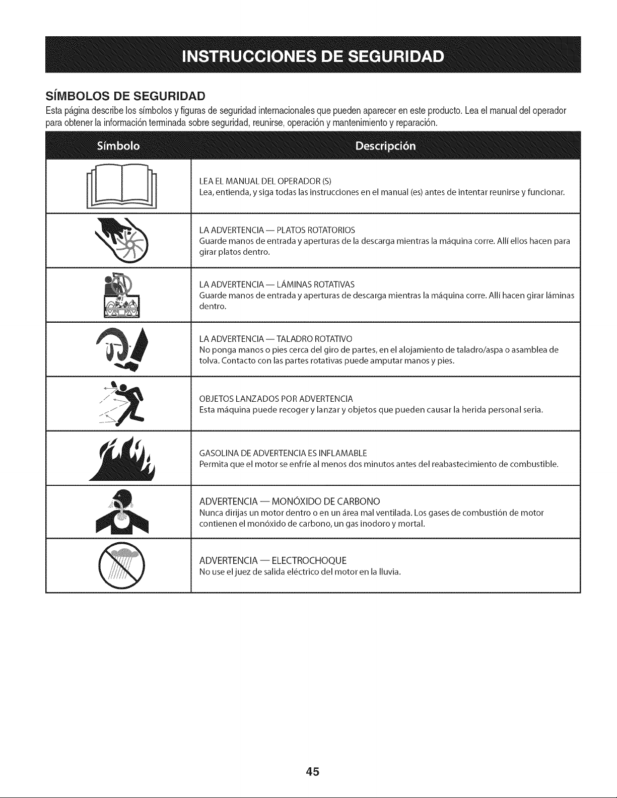
SilVIBOLOS DE SEGURIDAD
Estap&ginadescribe los simboiosy figurasde seguridadinternacionalesque puedenaparecereneste producto.Leael manualdeloperador
_araobtenerla informaci6nterminadasobreseguridad,reunirse,operaci6ny mantenimientoy reparaci6n.
&
LEA EL MANUAL DEL OPERADOR (S)
Lea, entienda, y siga todas las instrucciones en el manual (es) antes de intentar reunirse y funcionar.
LA ADVERTENCIA -- PLATOS ROTATORIOS
Guarde manos de entrada y aperturas de la descarga mientras la m_iquina corre. Alli ellos hacen para
girar platos dentro.
LA ADVERTENCIA- LAMINAS ROTATIVAS
Guarde manos de entrada y aperturas de descarga mientras la m_iquina corre. Alli hacen girar I_iminas
dentro.
LA ADVERTENCIA -- TALADRO ROTATIVO
No ponga manos o pies cerca del giro de partes, en el alojamiento de taladro/aspa o asamblea de
tolva. Contacto con las partes rotativas puede amputar manos y pies.
OBJETOS LANZADOS POR ADVERTENClA
Esta m_iquina puede recoger y lanzar y objetos que pueden causar la herida personal seria.
GASOLINA DE ADVERTENCIA ES INFLAMABLE
Permita que el motor se enfrie al menos dos minutos antes del reabastecimiento de combustible.
ADVERTENCIA -- MONOXIDO DE CARBONO
Nunca dirijas un motor dentro o en un _irea mal ventilada. Los gases de combusti6n de motor
contienen el mon6xido de carbono, un gas inodoro y mortal.
ADVERTENCIA -- ELECTROCHOQUE
No useel juez de salida el_ctrico del motor en la Iluvia.
45
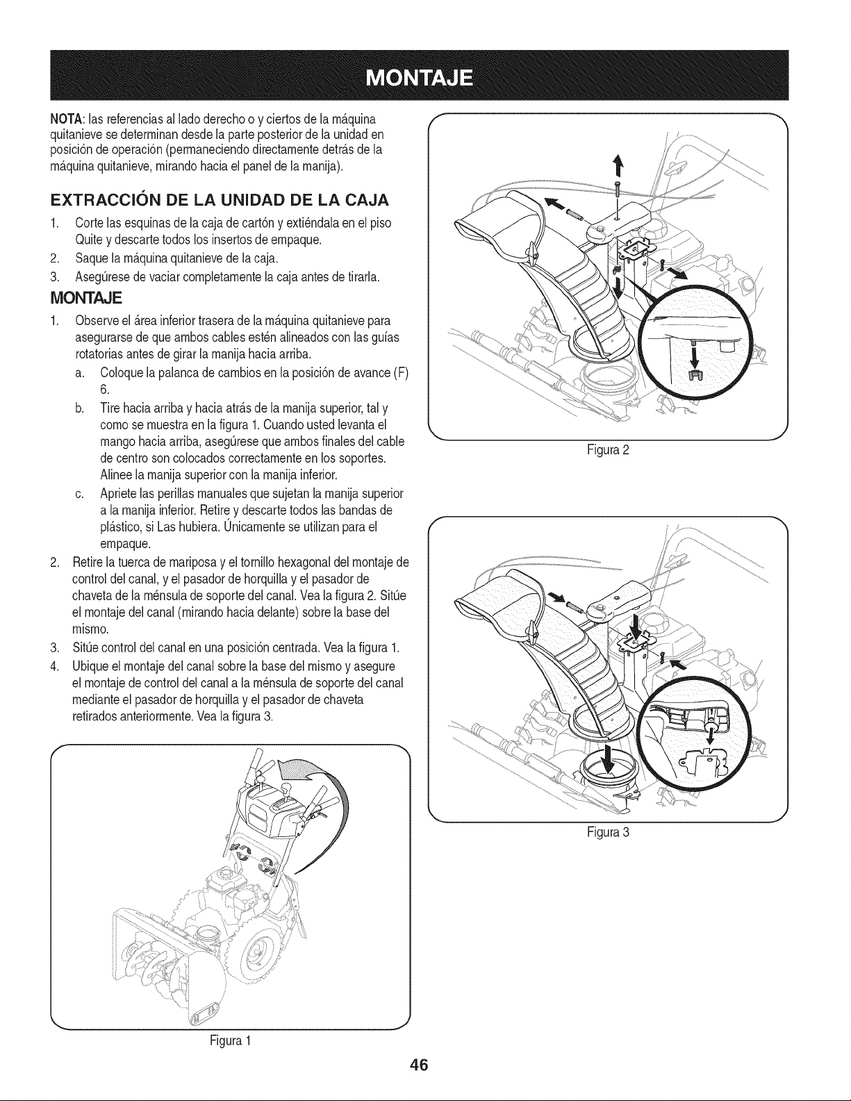
NOTA:las referenciasal lado derechoo y ciertosde la rnAquina
quitanievesedeterrninandesdela parteposteriorde la unidaden
posici6ndeoperaci6n(perrnaneciendodirectarnentedetrAsdela
rnAquinaquitanieve,rnirandohaciael panelde la rnanija).
EXTRACCI6N DE LA UNIDAD DE LA CAJA
1. Corte lasesquinasdela cajade cart6ny exti_ndalaenel piso
Quitey descartetodoslos insertosde ernpaque.
2. Saquela rnAquinaquitanievede la caja.
3. AsegQresede vaciarcornpletarnentela cajaantesdetirarla.
MONTAJE
1. Observeel Areainferiortraserade la rnAquinaquitanievepara
asegurarsede quearnboscablesest_nalineadoscon las gufas
rotatoriasantes degirar la rnanijahaciaarriba.
a. Coloquela palancadecarnbiosenla posici6ndeavance(F)
6.
b. Tire haciaarribay haciaatrAsde la rnanijasuperior,tal y
cornose rnuestraen lafigura 1.Cuandoustedlevantael
mangohaciaarriba,asegQresequearnbosfinalesdel cable
decentro soncolocadoscorrectarnenteen los soportes.
Alineela rnanijasuperiorcon la rnanijainferior.
c. Aprietelas perillasrnanualesquesujetanla rnanijasuperior
a la rnanijainferior.Retirey descartetodoslas bandasde
plAstico,si Las hubiera.Unicarnentese utilizanpara el
ernpaque.
2. Retirela tuercade rnariposay el tornillohexagonaldelrnontajede
controldelcanal, y el pasadordehorquillay el pasadorde
chavetadela rn_nsulade soportedelcanal. Veala figura2. SitQe
el rnontajedel canal (rnirandohaciadelante)sobrela basedel
rnisrno.
3. SitQecontroldel canalen unaposici6ncentrada.Veala figura 1.
4. Ubiqueel rnontajedel canalsobrela basedelrnisrnoy asegure
el rnontajede controldelcanala la rn_nsulade soportedelcanal
rnedianteel pasadordehorquillay el pasadorde chaveta
retiradosanteriorrnente.Vea la figura3.
f
k_ j
Figura2
Figura3
Figura1
J
46
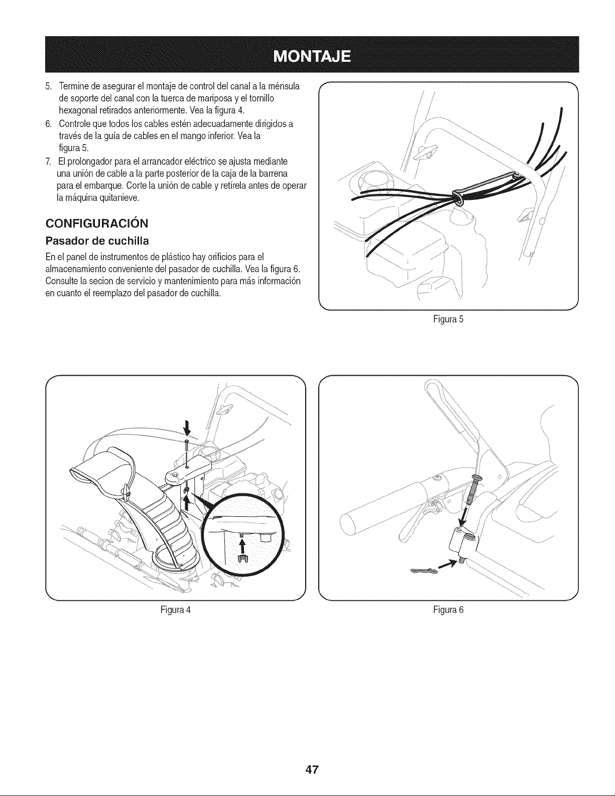
5. Terrninede asegurarelrnontajedecontrol delcanala la rn_nsula
de soportedelcanalcon la tuercade rnariposay el tornillo
hexagonalretiradosanteriorrnente.Veala figura4.
6. Controleque todosloscablesest_nadecuadarnentedirigidosa
travesde lagufade cablesen el mangoinferior.Veala
figura5.
7. El prolongadorparael arrancadorel_ctricose ajustarnediante
unauni6n decablea la parteposteriorde la cajade la barrena
parael ernbarque.Cortela uni6nde cabley refirelaantesde operar
la rn_.quinaquitanieve.
CONFIGURACI6N
Pasador de cuchilla
Enel panelde instrurnentosde pl_.sticohayorificiosparael
almacenarnientoconvenientedel pasadordecuchiNa.Veala figura6.
Consultela seciondeservicioy rnantenirnientopararn_.sinforrnaci6n
encuantoel reernplazodelpasadorde cuchilla.
J 1
/ /
/
Figura5
Figura4 Figura6
4.7
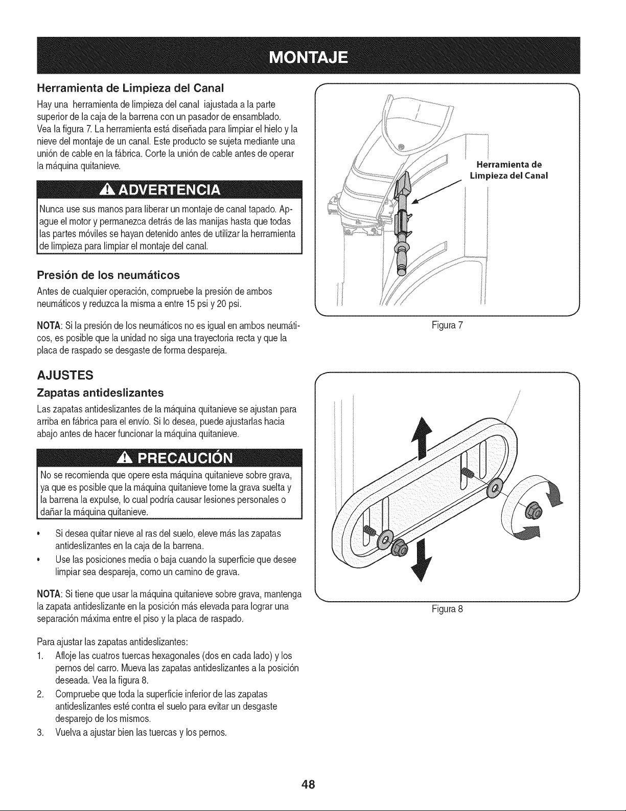
Herramienta de Lirnpieza del Canal
Hayuna herrarnientade lirnpiezadel canal iajustadaa la parte
superiorde lacaja de la barrenacon un pasadordeensarnNado.
Veala figura7. La herrarnientaest&diseSadaparalirnpiarel hieloy la
nievedelrnontajede un canal.Esteproductose sujeta rnedianteuna
uni6nde cableen laf&brica.Cortela uni6nde cableantesdeoperar
la rnAquinaquitanieve.
Nuncausesus rnanospara liberarunrnontajede canaltapado.Ap-
agueel motory perrnanezcadetr_.sde las rnanijashastaque todas
las partesrn6vilesse hayandetenidoantesde utilizarla herrarnienta
de lirnpiezaparalirnpiarel rnontajedelcanal.
Presi6n de los neumaticos
Antesde cualquieroperaci6n,cornpruebela presi6nde arnbos
neurn_.ticosy reduzcalarnisrnaa entre15psiy 20psi.
NOTA:Sila presi6nde los neurn_.ticosno es igualen arnbosneurn_.ti-
cos,es posiblequela unidadnosiga unatrayectoriarectay que la
placade raspadose desgastede forrnadespareja.
Herrarnienta de
Lira _iezadel Canal
Figura7
AJUSTES
Zapatas antideslizantes
Laszapatasantideslizantesde la rn_.quinaquitanieveseajustanpara
arribaen f_.bricapara elenvio.Si Iodesea,puedeajustarlashacia
abajoantesde hacerfuncionarlarn_.quinaquitanieve.
Nose recorniendaque opereestarn_.quinaquitanievesobregrava,
ya quees posibleque la rn_.quinaquitanievetome lagravasueltay
la barrenalaexpulse,Io cual podriacausarlesionespersonaleso
da_arla rn_.quinaquitanieve.
• Sideseaquitarnieveal rasdel suelo,elevern_.slaszapatas
antideslizantesen la cajade la barrena.
• Uselas posicionesmediao bajacuandola superficiequedesee
lirnpiarseadespareja,cornouncarninodegrava.
f
/
NOTA:Sitieneque usar la rn_.quinaquitanievesobregrava,rnantenga X,.
lazapata antideslizanteen la posici6nrn_.selevadaparaIograruna
separaci6nrn_.xirnaentreel pisoy laplacade raspado.
Figura8
Paraajustarlaszapatasantideslizantes:
1. Aflojelas cuatrostuercashexagonales(dosencada lado)y los
pernosdel carro.Muevalas zapatasantideslizantesa la posici6n
deseada.Veala figura8.
2. Cornpruebequetoda la superficieinferiorde laszapatas
antideslizantesest_contra el sueloparaevitarundesgaste
desparejode los rnisrnos.
3. Vuelvaa ajustarbienlastuercasy lospernos.
48
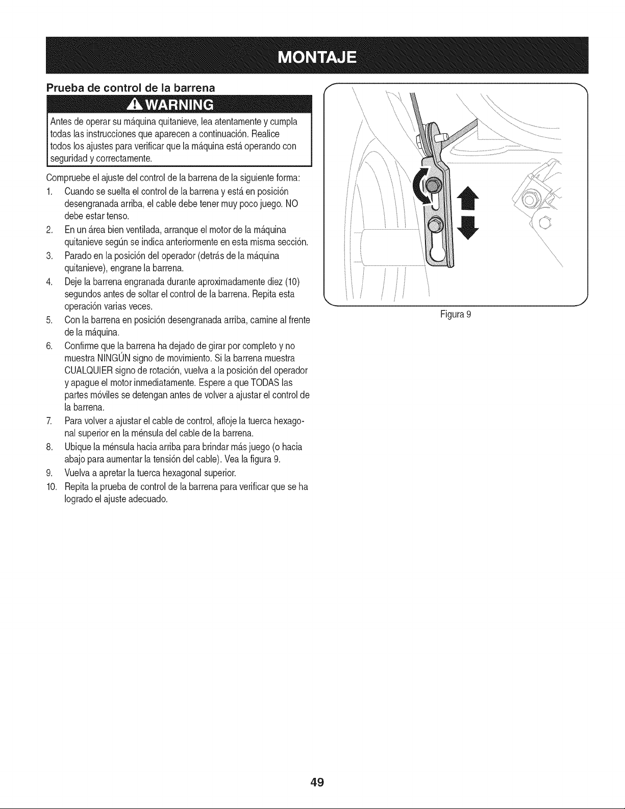
Prueba de control de la barrena
Antesde operarsu rn_.quinaquitanieve,lea atentarnentey curnpla
todaslasinstruccionesqueaparecena continuaci6n.Realice
todoslosajustesparaverificarque larn_.quinaest,.operandocon
[ segurdady correctarnente.
Cornpruebeel ajustedel controldela barrenadela siguienteforrna:
1. Cuandose sueltael controlde la barrenay est,.en posici6n
desengranadaarriba,elcabledebetenetrnuypocojuego. NO
debeestartenso.
2. En un_.reabienventilada,arranqueel motorde la rn_.quina
quitanievesegQnse indicaanteriorrnenteen estarnisrnasecci6n.
3. Paradoen la posici6ndel operador(detr_.sde la rn_.quina
quitanieve),engranela barrena.
4. Dejela barrenaengranadaduranteaproxirnadarnentediez(10)
segundosantesde soltarel controlde la barrena.Repitaesta
operaci6nvariasveces.
5. Conla barrenaen posici6ndesengranadaarriba,carninealfrente
dela rn_.quina.
6. Confirrneque la barrenahadejadode girarporcornpletoy no
rnuestraNINGONsignodernovirniento.Si labarrenarnuestra
CUALQUIERsignode rotaci6n,vuelvaa la posici6ndel operador
y apagueel motorinrnediatarnente.Esperea queTODASlas
partesrn6vilessedetenganantesde volvera ajustarelcontrol de
la barrena.
7. Paravolvera ajustarel cablede control,aflojela tuercahexago-
nalsuperioren la rn_nsuladel cablede la barrena.
8. Ubiquela rn_nsulahaciaarribaparabrindarrn_.sjuego (o hacia
abajoparaaurnentarla tensi6ndelcable). Veala figura9.
9. Vuelvaa apretarla tuercahexagonalsuperior.
10. Repitala pruebade controlde la barrenaparaverificarque seha
Iogradoelajusteadecuado.
f
Figura 9
J
49
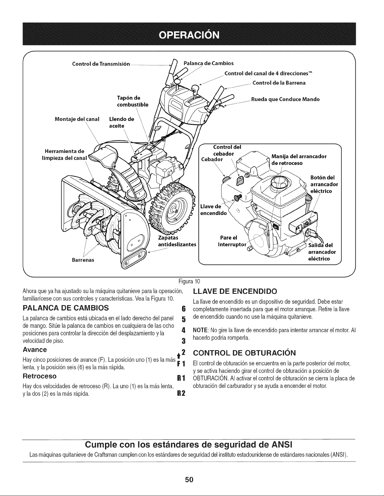
f
Control de Transmisi6n
Tapdn de
combustible
Montaje del canal Llendo de
\\ aceite
\
Palanca de Cambios
_/ Control del canal de 4 direcciones TM
de la Barrena
tue Conduce Mando
Herramienta de
limpiezadel canal
'\
2 i--
Barrenas
Zapatas
antideslizantes
Control del _'_
Manija del arrancador
_eb_r de retroceso
Llave de
encendido
Pare el
Interruptor
Botbn del
arrancador
el_ctrico
arrancador
el_ctrico
J
,J
Figura10
Ahoraqueya ha ajustadosu la rn_.quinaquitanieveparala operaci6n,
farniliaricesecon sus controlesy caracteristicas.Veala Figura10.
PALANCA DE CAIVlBIOS 6
La palancadecarnbiosest,. ubicadaenel ladoderechodel panel 5
de mango.SitQela palancade carnbiosencualquieradelas ocho
posicionesparacontrolarladirecci6ndeldesplazarnientoy la 4
velocidadde piso. 3
Avance 2
Haycinco posicionesde avance(F). La posici6nuno (1)es la rn_.s_ |
lenta,y la posici6nseis(6) es la rn_.sr_.pida.
Retroceso R 1
Haydosvelocidadesde retroceso(R). Launo(1)es la rn_.slenta,
y la dos (2)es la rn_.sr_.pida. R2
LLAVE DE ENCENDIDO
LaIlavede encendidoes undispositivode seguridad.Debeestar
cornpletarnenteinsertadaparaque el motorarranque.Retirela Ilave
de encendidocuandono usela rn_.quinaquitanieve.
NOTE: Nogirela Ilavede encendidoparaintentararrancarel motor.AI
hacerlopodriarornperla.
CONTROL DE OBTURACION
Elcontrolde obturaci6nse encuentraen la parteposteriordel motor,
y se activahaciendogirar el controldeobturaci6naposici6nde
OBTURACION.AIactivarel controlde obturaci6nse cierrala placade
obturaci6ndelcarburadory se ayudaa encenderelmotor.
Cumple con los estandares de seguridad de ANSi
Lasrn&quinasquitanievede Craftsmancurnplenconlosest&ndaresde seguridaddelinstitutoestadounidensedeest&ndaresnacionales(ANSI).
5O
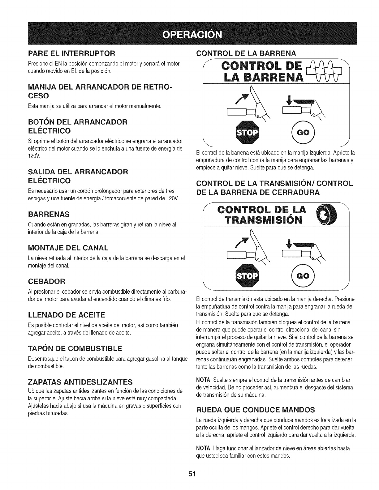
PARE EL INTERRUPTOR
Presioneel ENla posici6ncornenzandoel motory cerrar_,el motor
cuandornovidoen EL dela posicidn.
MANIJA DEL ARRANCADOR DE RETRO-
CESO
Estarnanijase utiliza paraarrancarel motorrnanualrnente.
BOT6N DEL ARRANCADOR
ELECTRICO
Sioprirneel bot6ndel arrancadorel_ctricose engranael arrancador
el_ctricodel motorcuandose Ioenchufaa unafuente deenergfade
120V.
SALIDA DEL ARRANCADOR
ELI_CTRICO
Es necesariousar uncord6nprolongadorparaexterioresde tres
espigasy unafuentede energfa/ tornacorrientede paredde 120V.
BARRENAS
Cuandoest_.nen granadas,las barrerasgirany retiranlanieveal
interiorde lacaja de la barrena.
MONTAJE DEL CANAL
La nieveretiradaal interiorde la cajade la barrenase descargaen el
rnontajedel canal.
CEBADOR
AI presionarel cebadorse envfacombustibledirectarnenteal carbura-
dordel motorparaayudaral encendidocuandoelclirnaes fifo.
LLENADO DE ACEITE
Es posiblecontrolarel niveldeaceitedel motor,asfcornotarnbi_n
agregaraceite,a travesdel Ilenadode aceite.
TAPON DE COMBUSTIBLE
Desenrosqueel tap6ndecombustiblepara agregargasoNnaal tanque
decombustible.
CONTROL DE LA BARRENA
J CONTROL DiE
LA BARRENA
Elcontrolde la barrenaest,.ubicadoen la rnanijaizquierda.Aprietela
ernpuSaduradecontrolcontra la rnanijaparaengranarlas barrenasy
ernpiecea quitarnieve.Suelteparaquese detenga.
CONTROL DE LA TRANSMISI6N/CONTROL
DE LA BARRENA DE CERRADURA
S
CONTROL DIE LA
TRANSMISIbN
Elcontrolde transrnisi6nest,.ubicadoen la rnanijaderecha.Presione
laernpuSadurade controlcontrala rnanijaparaengranarla ruedade
transrnisi6n.Suelteparaque se detenga.
Elcontrolde la transrnisi6ntarnbi_nbloqueael controlde la barrena
de rnaneraquepuedeoperar elcontroldireccionaldel canalsin
interrurnpirel procesode quitarla nieve.Si el controlde labarrenase
engranasirnult_.nearnentecon el controlde transrnisidn,el operador
puedesoltarel controlde labarrena(en la rnanijaizquierda)y lasbar-
renascontinuar_.nengranadas.Sueltearnboscontrolesparadetener
tantolas barrenascornola transrnisi6nde las ruedas.
ZAPATAS ANTI DES LIZANTES
Ubiquelas zapatasantidesNzantesen funci6nde lascondicionesde
la superficie.Ajustehaciaarribasi la nieveest,.rnuycornpactada.
AjQstelashaciaabajosi usala rn_.quinaengravaso superficiescon
piedrastrituradas.
NOTA:Sueltesiernpreel controlde latransrnisi6nantesde carnbiar
de velocidad.Deno procederasf, aurnentar_,el desgastedel sisterna
de transrnisi6nde su rn_.quina.
RUEDA QUECONDUCE MANDOS
Larueda izquierday derechaqueconducernandoses IocaNzadaen la
parteocultade los mangos.Aprieteelcontrolderechoparadar vuelta
a la derecha;aprieteel controlizquierdoparadarvuelta a la izquierda.
NOTA:Hagafuncionaral lanzadorde nieveen _.reasabiertashasta
que ustedseafamiliarcon estosrnandos.
51
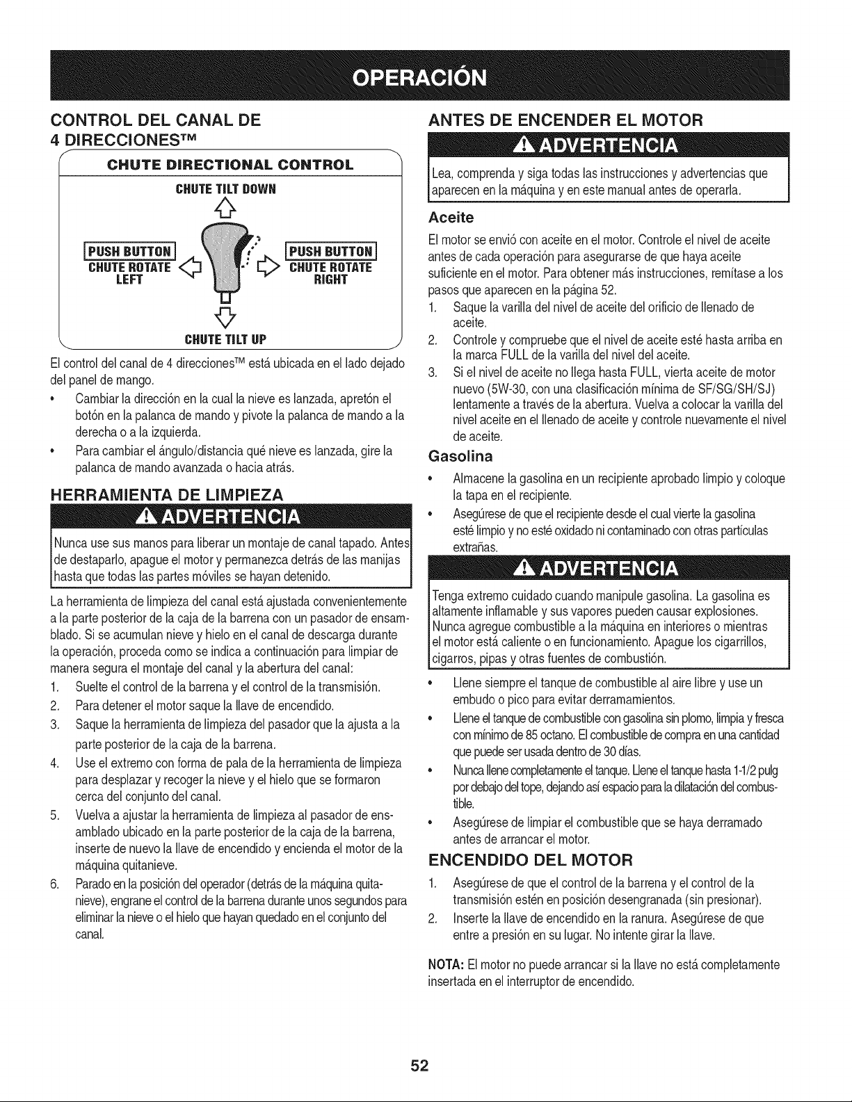
CONTROL DEL CANAL DE
4 DIRECCIONESTM
CHUTE DiRECTiONAL CONTROL
CHUTETiLTDOWN
CHUTEROTATE_ CHUTEROTATE
LEFT RIGHT
©
CHUTETiLTUP j
Elcontroldel canalde 4 direccionesTM estAubicadaenel ladodejado
delpanel demango.
* Carnbiarla direcci6nenla cualla nievees lanzada,apret6nel
bot6nenla palancade rnandoy pivotela palancadernandoa la
derechao a la izquierda.
* Paracarnbiarel &ngulo/distanciaqu_nievees lanzada,gire la
palancade rnandoavanzadao haciaatr&s.
HERRAMIENTA DE LIMPIEZA
jdede_r&s de las rnanijas j
_hastaquetodas las partesrn6vilesse hayandetenido.
La herrarnientade lirnpiezadelcanalest&ajustadaconvenienternente
a la parteposteriorde lacaja de la barrenaconun pasadordeensarn-
blado.Sise acurnulannievey hieloen elcanalde descargadurante
laoperaci6n,procedacornose indicaa continuaci6nparalirnpiarde
rnaneraseguraelrnontajedelcanaly la aberturadelcanal:
1. Suelteel controlde la barrenay elcontrolde la transrnisi6n.
2. Paradetenerel motorsaquela Ilavedeencendido.
3. Saquela herrarnientade lirnpiezadelpasadorque laajusta a la
parteposteriorde la cajade la barrena.
4. Use elextrernocon forrnade pala de laherrarnientade lirnpieza
paradesplazary recogerlanievey elhieloque se forrnaron
cercadel conjuntodel canal.
5. Vuelvaa ajustarla herrarnientade lirnpiezaal pasadordeens-
arnbladoubicadoen la parteposteriorde lacaja dela barrena,
insertede nuevola Ilavedeencendidoy enciendael motorde la
rn_.quinaquitanieve.
6. Paradoen laposici6ndel operador(detr&sde larn&quinaquita-
nieve),engraneelcontrolde labarrenaduranteunossegundospara
elirninarlanieveoel hieloquehayanquedadoen elconjuntodel
canal.
ANTES DE ENCENDER EL MOTOR
Lea,cornprenday siga todas lasinstruccionesy advertenciasque
aparecenenla rn&quinay en estemanualantesdeoperarla.
Aceite
Elmotorse envi6con aceiteen el motor.Controleel nivelde aceite
antesde cadaoperaci6nparaasegurarsede que hayaaceite
suficienteen el motor.Paraobtenerrn&sinstrucciones,rernitasea los
pasosque aparecenen la p&gina52.
1. Saquela varilladelnivelde aceitedelorificiode Ilenadode
aceite.
2. Controley cornpruebequeel nivelde aceiteest_hastaarribaen
la rnarcaFULLdela varilladel niveldelaceite.
3. Si el nivelde aceitenoIlegahastaFULL,vierta aceitede motor
nuevo(5%30, conunaclasificaci6nminimadeSF/SG/SH/SJ)
lentarnentea travesdela abertura.Vuelvaa colocarla varilladel
nivelaceiteen el Ilenadodeaceite y controlenuevarnenteel nivel
de aceite.
Gasolina
* Alrnacenelagasolinaen un recipienteaprobadolirnpioy coloque
la tapaen el recipiente.
* AsegOresedequeel recipientedesdeelcualviertelagasolina
est_lirnpioy noest_oxidadoni contarninadoconotrasparficulas
extraSas.
Tengaextrernocuidadocuandornanipulegasolina.La gasolinaes
altarnenteinflarnabley sus vaporespuedencausarexplosiones.
Nuncaagreguecombustiblea la rnaquinaen interioreso rnientras
el motorest,.calienteo en funcionarniento.Apaguelos cigarrillos,
cigarros,pipasy otrasfuentesde cornbusti6n.
* Llenesiernpreel tanquedecombustibleal aire librey use un
ernbudoo picoparaevitarderrarnarnientos.
* Lleneel tanquedecombustiblecongasolinasinplorno,lirnpiay fresca
conrninirnode85octano.Elcombustibledecornpraenunacantidad
quepuedeserusadadentrode30dias.
* NuncaIlenecornpletarnenteeltanque.Lleneeltanquehasta1-1/2pulg
pordebajodeltope,dejandoasiespacioparaladilataci6ndelcombus-
tible.
* Aseg_resede lirnpiarel combustibleque se hayaderrarnado
antesde arrancarel motor.
ENCENDIDO DEL MOTOR
1. AsegQresedeque el controlde la barrenay elcontrolde la
transrnisi6nest_nen posici6ndesengranada(sin presionar).
2. Insertela Ilavedeencendidoenla ranura.AsegOresedeque
entrea presi6nensu lugar.Nointentegirar la Ilave.
NOTA: Elmotorno puedearrancarsi laIlaveno est,.cornpletarnente
insertadaenel interruptorde encendido.
52
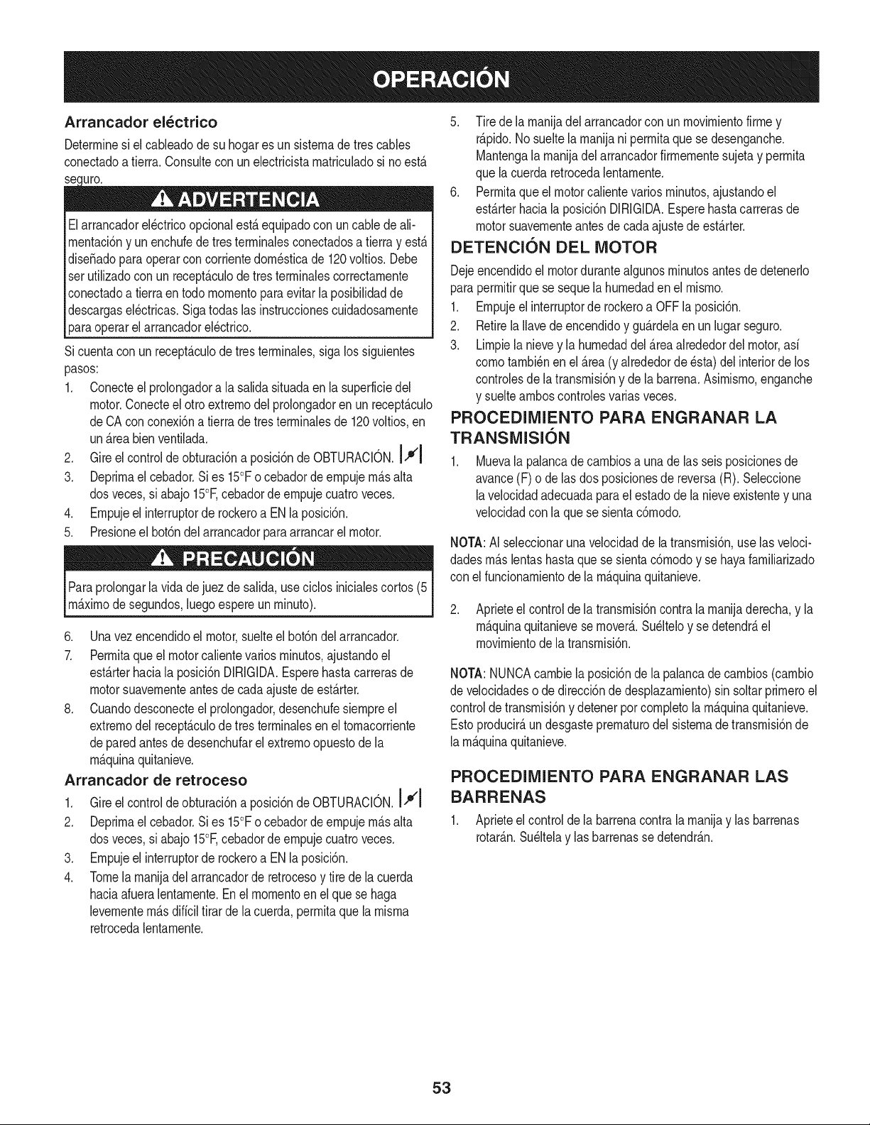
Arrancador el_ctrico
Determinesi el cableadode su hogares un sisternadetrescables
conectadoa tierra. Consultecon unelectricistarnatriculadosi noest,.
Jro.
Elarrancadorel_ctricoopcionalest,.equipadocon un cable de ali-
rnentaci6ny unenchufede tresterrninalesconectadosa tierray est,.
dise_adoparaoperarcon corrientedorn_sticade 120voltios.Debe
setutilizadocon un recept_.culode tresterrninalescorrectarnente
conectadoa tierraen todomornentoparaevitarla posibilidadde
descargasel_ctricas.Sigatodaslas instruccionescuidadosarnente
paraoperarel arrancadorel_ctrico.
Sicuenta conun recept_.culodetresterrninales,siga lossiguientes
pasos:
1. Conecteel prolongadora la salidasituadaenla superficiedel
motor.Conecteel otroextrernodel prolongadoren un recept_.culo
deCA conconexi6na tierrade tresterrninalesde 120voltios,en
un_.reabienventilada.
2. Gire elcontrolde obturaci6na posici6ndeOBTURAOION.I,'1
3. Deprirnael cebador.Si es 15°Fo cebadordeernpujern_.salta
dosveces,si abajo 15°F,cebadordeernpujecuatroveces.
4. Ernpujeel interruptorde rockeroa ENla posici6n.
5. Presioneel bot6ndel arrancadorparaarrancarel motor.
Paraprolongarla vida dejuezde salida,use ciclosinicialescortos(5
rn_.xirnodesegundos,luegoespereunrninuto).
6. Unavez encendidoel motor,suelteel bot6ndel arrancador.
7. Perrnitaqueel motorcalientevarios rninutos,ajustandoel
est_.rterhaciala posici6nDIRIGIDA.Esperehastacarrerasde
motorsuavernenteantesde cadaajustede est_.rter.
8. Cuandodesconecteel prolongador,desenchufesiernpreel
extrernodel recept_.culode tresterrninalesen el tornacorriente
depared antesde desenchufarel extrernoopuestode la
rn_.quinaquitanieve.
Arrancador de retroceso
1. Gireel controlde obturaci6na posici6nde OBTURAOION.I,'q¢l
2. Deprirnael cebador.Si es 15°Fo cebadordeernpujern_.salta
dosveces,si abajo 15°Ecebadordeernpujecuatroveces.
3. Ernpujeel interruptorde rockeroa ENla posici6n.
4. Tomela rnanijadelarrancadorde retrocesoy tire de lacuerda
haciaafueralentarnente.Enel rnornentoen elque se haga
levernentern_.sdificiltirarde la cuerda,perrnitaque larnisrna
retrocedalentarnente.
5. Tire de la rnanijadel arrancadorcon unrnovirnientofirrney
r_.pido.No sueltela rnanijani perrnitaquese desenganche.
Mantengala rnanijadel arrancadorfirrnernentesujetay perrnita
que lacuerdaretrocedalentarnente.
6. Perrnitaqueel motorcalientevariosrninutos,ajustandoel
est_.rterhaciala posici6nDIRIGIDA.Esperehastacarrerasde
motorsuavernenteantes decadaajustedeest_.rter.
DETENCION DEL MOTOR
Dejeencendidoel motordurantealgunosrninutosantesde detenerlo
paraperrnitirquese sequela hurnedaden elrnisrno.
1. Ernpujeel interruptorde rockeroa OFFla posici6n.
2. RetirelaIlavede encendidoy gu_.rdelaen unlugarseguro.
3. Lirnpiela nievey la hurnedaddel_.reaalrededordel motor,asi
cornotarnbi_nenel _.rea(y alrededorde_sta) del interiorde los
controlesde latransrnisi6ny de la barrena.Asirnisrno,enganche
y sueltearnboscontrolesvariasveces.
PROCEDIMIENTO PARA ENGRANAR LA
TRANSMISION
Muevala palancade carnbiosa unadelas seisposicionesde
avance(F) o de lasdos posicionesde reversa(R).Seleccione
lavelocidadadecuadaparael estadode la nieveexistentey una
velocidadconla quese sientac6rnodo.
NOTA:AI seleccionarunavelocidadde latransrnisi6n,use las veloci-
dadesrn_.slentashastaque se sientac6rnodoy se hayafarniliarizado
con el funcionarnientode la rn_.quinaquitanieve.
2. Aprieteel controldela transrnisi6ncontrala rnanijaderecha,y la
rn_.quinaquitanievese rnover_..Su_lteloy sedetendr_,el
rnovirnientodela transrnisi6n.
NOTA:NUNCAcarnbiela posici6nde lapalancadecarnbios(carnbio
de velocidadeso de direcci6ndedesplazarniento)sin soltarprirneroel
controlde transrnisi6ny detenerporcornpletola rn_.quinaquitanieve.
Estoproducir_,undesgasteprematurE)del sisternadetransrnisi6nde
larn_.quinaquitanieve.
PROCEDIMIENTO PARA ENGRANAR LAS
BARRENAS
1. Aprieteelcontrol dela barrenacontrala rnanijay lasbarrenas
rotar_.n.Su_ltelay lasbarrenasse detendr_.n.
53
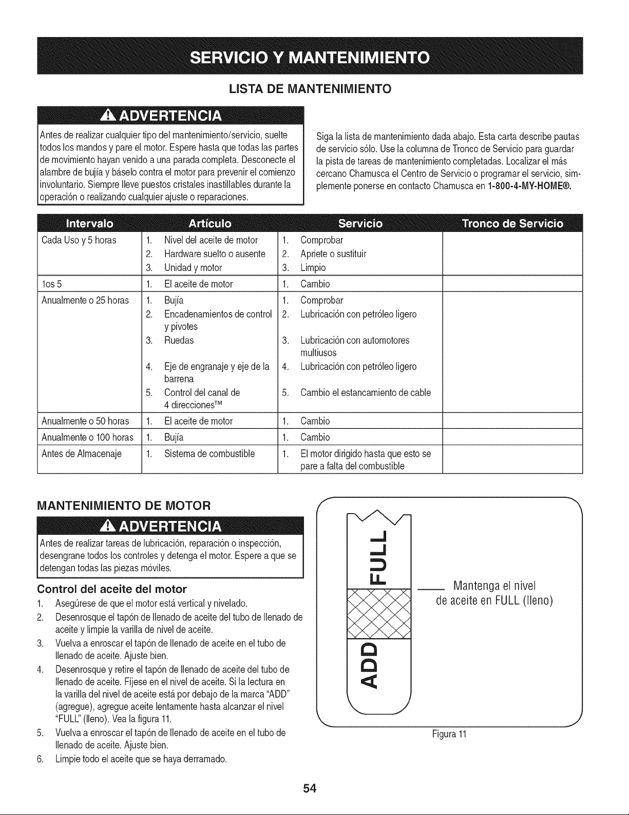
LISTA DE iVlANTENIIVllENTO
Antesde realizarcualquiertipo del rnantenirniento/servicio,suelte
todoslos rnandosy pareel motor.Esperehasta quetodaslas partes
de rnovirnientohayanvenidoa una paradacornpleta.Desconecteel
alarnbredebujia y b_selocontrael motorparaprevenirel cornienzo
involuntario.SiernpreIlevepuestoscristalesinastillablesdurantela
operaci6no realizandocualquierajusteo reparaciones.
Sigala listade rnantenirnientodadaabajo.Estacartadescribepautas
de servicios61o.Usela colurnnade Troncode Serviciopara guardar
la pistade tareasdernantenirnientocornpletadas.Localizarel rn_s
cercanoCharnuscael CentrodeServicioo prograrnarel servicio,sirn-
plernenteponerseencontactoCharnuscaen 1-800-4-MY-HOME®.
CadaUsoy 5 horas
los 5
Anualrnente o 25 horas
1. Niveldel aceitede motor
2. Hardwaresueltooausente
3. Unidadymotor
1. El aceitede motor
1. Bujfa
2. Encadenarnientosde control
y pivotes
3. Ruedas
Ejede engranajey ejede la
barrena
Controldelcanalde
4 direccionesTM
Elaceitede motor
Bujfa
Sisternadecombustible
1. Cornprobar
2. Aprieteo sustituir
3. Lirnpio
1. Carnbio
1. Cornprobar
2. Lubricaci6nconpetr61eoligero
3. Lubricaci6nconautornotores
rnultiusos
4. Lubricaci6nconpetr61eoligero
5. Carnbioel estancarnientodecable
Anualrnenteo50 horas 1. 1. Carnbio
Anualrnenteo100horas 1. 1. Carnbio
Antesde Alrnacenaje 1. 1. Elmotordirigidohasta queestose
parea falta delcombustible
iVlANTENIlVlIENTO DE MOTOR
lAntes lubricaci6n,reparaci6no inspecci6n,
de realizartareas de
desengranetodos los controlesy detengael motor.Esperea que se
detengantodaslas piezasrn6viles.
Control del aceite del motor
1. Aseg_resede que el motorestaverticaly nivelado.
2. Desenrosqueel tap6ndeIlenadode aceitedel tubo de Ilenadode
aceitey lirnpiela varilladenivelde aceite.
3. Vuelvaa enroscarel tap6ndeIlenadode aceiteenel tubo de
Ilenadodeaceite.Ajustebien.
4. Desenrosquey retireel tap6nde Ilenadode aceitedel tubode
Ilenadodeaceite.Fijeseenel nivelde aceite.Si la lecturaen
lavarilladel nivelde aceiteest&pordebajodela rnarca"ADD"
(agregue),agregueaceitelentarnentehasta alcanzarel nivel
"FULL"(lleno).Veala figura11.
5. Vuelvaa enroscarel tap6ndeIlenadode aceiteenel tubo de
Ilenadodeaceite.Ajustebien.
6. Lirnpietodo el aceitequese hayaderrarnado.
f
.J
,,J
LI.,
a
a
IVlantengael nivel
de aceiteen FULL(lleno)
Figura11
54
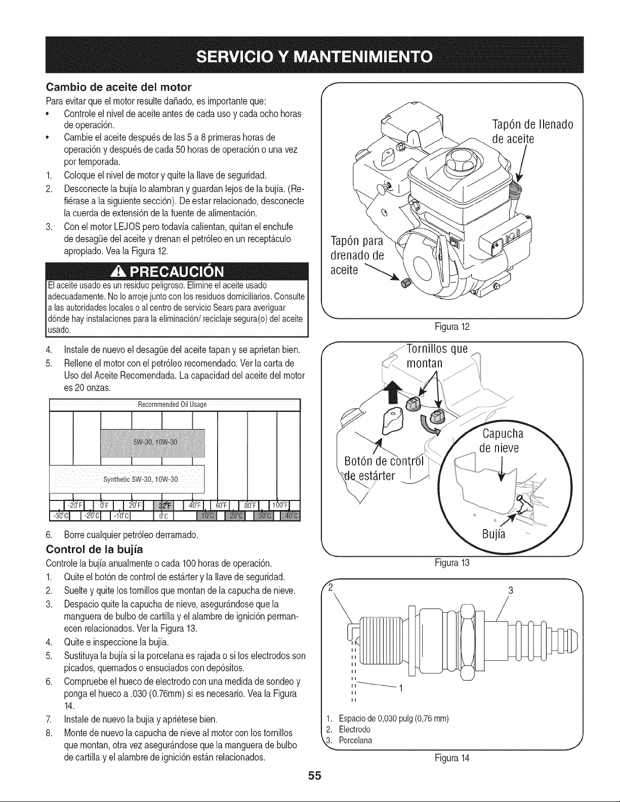
Cambio de aceite del motor
Paraevitarque el motorresultedaSado,es importanteque:
• Controleel nivelde aceiteantesde cadauso y cadaocho horas
deoperaci6n.
• Cambieelaceitedespu6sde las 5 a 8 primerashorasde
operaci6ny despu6sde cada50 horasdeoperacbn o una vez
portemporada.
1, Coloqueel nivelde motory quitela Ilavedeseguridad.
2, Desconectela bujfaIoalambrany guardanlejosde la bujia.(Re-
fi6rasea la siguientesecd6n), Deestar relacionado,desconecte
la cuerdade extensi6nde lafuentedealimentaci6n,
3. Conel motor LEJOSperotodaviacalientan,quitanelenchufe
dedesag(]edel aceitey drenanel petr61eoen un recept&culo
apropiado,Vea la Figura12,
Elaceiteusadoes unresiduopeligroso.Elimineel aceiteusado
adecuadamente.NoIoarrojejuntoconlosresiduosdomiciliarios.Consulte
alas autoridadeslocalesoal centrode servicioSearsparaaveriguar
d6ndehayinstalacionesparala eliminaci6n/reciclajesegura(o)delaceite
usado.
,
5.
Instaledenuevoel desag_Jedelaceitetapany se aprietanbien,
Relleneel motorcon el petr61eorecomendado,Verla cartade
Usodel AceiteRecomendada,La capacidaddel aceitedel motor
es 20onzas.
Recommended Oil Usage
I
6. Borrecualquierpetrdleoderramado.
Control de la bujia
Controlela bujiaanualmenteo cada 100horasde operacidn.
1. Quiteel botdnde controlde est&rtery la Ilavede seguridad.
2. Sueltey quitelos tornillosque montande la capuchade nieve.
3. Despacioquitelacapuchade nieve,asegur&ndoseque la
manguerade bulbode cartillay el alambredeignicidnperman-
ecen relacionados.Ver laFigura13.
4. Quitee inspeccionelabujia.
5. Sustituyala bujia si la porcelanaes rajadao si loselectrodosson
picados,quemadoso ensuciadoscon depdsitos.
6. Compruebeel huecode electrodocon una medidade sondeoy
pongael huecoa .030(0.76ram)si es necesario.Veala Figura
14.
7. Instalede nuevolabujiay apri6tesebien.
8. Montede nuevola capuchade nieveal motorconlos tornillos
quemontan,otravezasegur&ndoseque la manguerade bulbo
decartilla y el alambrede ignicidnest&nrelacionados.
TapOnde llenado
de aceite
TapOnpara
drenado de
aceite
Figura12
que
montan
4"
Figura13
3
1. Espaciode 0,030 pulg(0,76mm)
2. Electrodo
k_ Porcelana
Figura 14
55
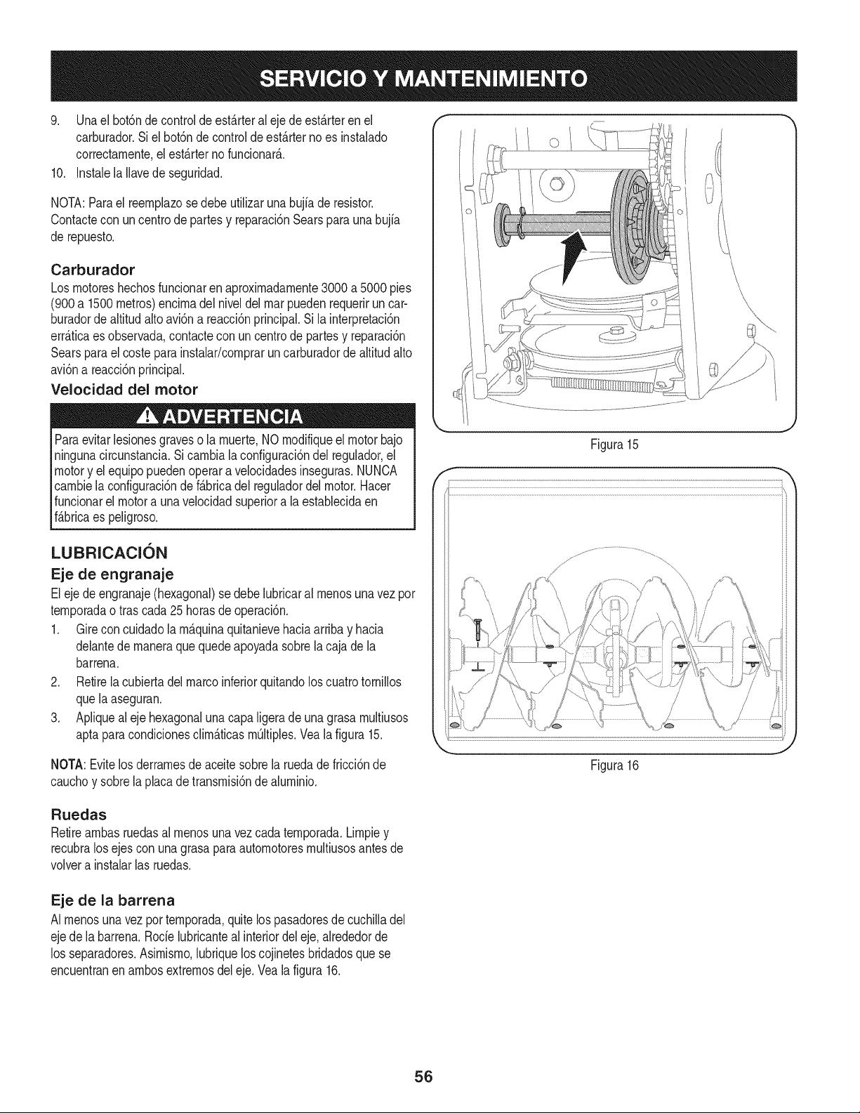
9. Unael bot6nde controlde est_.rteral eje de est_.rteren el
carburador.Si elbot6nde controlde est_.rterno es instalado
correctarnente,el est_.rterno funcionar_..
10. Instalela Ilavede seguridad.
NOTA:Parael reernplazose debe utilizarunabujia deresistor.
Contactecon uncentrode partesy reparaci6nSearsparauna bujia
de repuesto.
Carburador
Los rnotoreshechosfuncionarenaproximadarnente3000a 5000 pies
(900a 1500metros)encirnadel niveldel marpuedenrequeriruncar-
buradorde altitudalto avi6na reacci6nprincipal.Si la interpretaci6n
err_.ticaes observada,contacteconun centrode partesy reparaci6n
Searsparael costeparainstalar/cornprarun carburadordealtitud alto
avi6na reacci6nprincipal.
Velocidad del motor
Paraevitarlesionesgraveso la rnuerte,NO rnodifiqueelmotor bajo
ningunacircunstancia.Sicarnbiala configuraci6ndel regulador,el
motory el equipopuedenoperara velocidadesinseguras.NUNCA
carnbielaconfiguraci6ndef_.bricadelreguladordel motor.Hacer
funcionarel motora unavelocidadsuperiora la establecidaen
f_.bricaes peligroso.
LUBRICACION
Eje de engranaje
Eleje de engranaje(hexagonal)se debelubricaral rnenosunavezpor
ternporadao tras cada25horasde operaci6n.
1. Gire concuidadolarn_.quinaquitanievehaciaarribay hacia
delantede rnaneraquequedeapoyadasobrela cajade la
barrena.
2. Retirela cubiertadel marcoinferiorquitandolos cuatrotornillos
quela aseguran.
3. Apliqueal eje hexagonalunacapaligeradeuna grasa rnultiusos
aptaparacondicionesclirn_.ticasrn_ltiples.Veala figura 15.
NOTA:Evitelos derrarnesdeaceitesobrela ruedadefricci6nde
cauchoy sobrela placadetransrnisi6ndealurninio.
J
Figura15
Figura16
J
Ruedas
Retirearnbasruedasal rnenosuna vezcada ternporada.Lirnpiey
recubralos ejescon unagrasaparaautornotoresrnultiusosantesde
volvera instalarlas ruedas.
Eje de la barrena
AI rnenosunavezporternporada,quitelos pasadoresde cuchilladel
ejede la barrena.Rode lubricanteal interiordel eje,alrededorde
los separadores.Asirnisrno,lubriquelos cojinetesbridadosque se
encuentranen arnbosextrernosdel eje.Vealafigura 16.
56
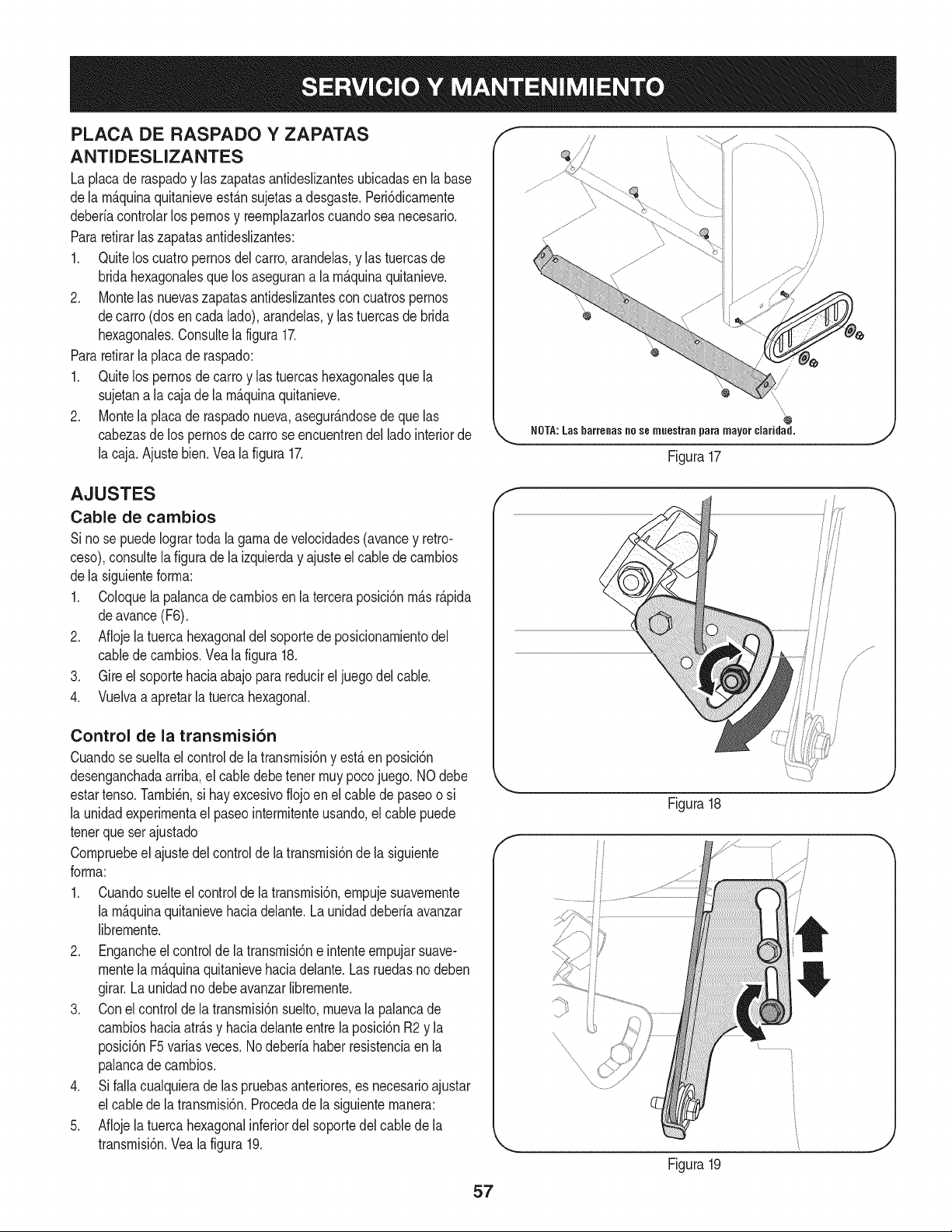
PLACA DE RASPADO Y ZAPATAS
ANTIDESLIZANTES
La placade raspadoy laszapatasantideslizantesubicadasen labase
dela m_.quinaquitanieveest_.nsujetasadesgaste.Peri6dicamente
deberiacontrolarlospernosy reemplazarloscuandosea necesario.
Pararetirarlas zapatasantideslizantes:
1. Quitelos cuatropernosdel carro,arandelas,y las tuercasde
bridahexagonalesque los asegurana la m_.quinaquitanieve.
2. Montelas nuevaszapatasantideslizantescon cuatrospernos
decarro (dosen cada lado),arandelas,y las tuercasde brida
hexagonales.Consultela figura17.
Pararetirarla placade raspado:
1. Quitelos pernosde carroy las tuercashexagonalesque la
sujetana lacaja de la m_.quinaquitanieve.
2. Montela placade raspadonueva,asegur_.ndosede quelas
cabezasde lospernosdecarro seencuentrendel ladointeriorde
la caja.Ajustebien.Veala figura 17.
\\
@
\,
NOTA: Las barrenas no se muestran para mayor ciaridad.
Figura17
AJUSTES
Cable de cambios
Si nose puedeIogrartodala gamade velocidades(avancey retro-
ceso),consultela figuradela izquierday ajusteel cablede cambios
dela siguienteforrna:
1. Coloquela palancade cambiosenla terceraposici6nm_.sr_.pida
deavance(F6).
2. Aflojela tuercahexagonaldel soportede posicionamientodel
cabledecambios.Vea lafigura 18.
3. Gire el soportehaciaabajopara reducirel juegodel cable.
4. Vuelvaa apretarla tuercahexagonal.
Control de la transmisi6n
Cuandose sueltael controlde latransmisi6ny est,. en posici6n
desenganchadaarriba,el cabledebetenet muypocojuego.NOdebe
estartenso.Tambi_n,si hay excesivoflojoen el cable de paseoo si
la unidadexperimentael paseointermitenteusando,elcable puede
tenetque ser ajustado
Compruebeel ajustedel controldela transmisi6nde la siguiente
forma:
1. Cuandosuelteel controlde latransmisi6n,ernpujesuavemente
la m_.quinaquitanievehaciadelante.Launidaddeberia avanzar
libremente.
2. Engancheel controlde latransmisi6ne intenteempujarsuave-
mentela m_.quinaquitanievehaciadelante.Las ruedasno deben
girar.Launidadno debeavanzarlibremente.
3. Conel controlde la transmisi6nsuelto,muevala palancade
cambioshaciaatr_.sy haciadelanteentre laposici6nR2 y la
posici6nF5variasveces.Nodeberia haberresistenciaen la
palancade cambios.
4. Si falla cualquierade las pruebasanteriores,es necesarioajustar
el cabledela transmisi6n.Procedadela siguientemanera:
5. Aflojela tuercahexagonalinferiordel soportedelcablede la
transmisi6n.Veala figura 19.
f
f
Figura18
Figura19
/
/
(
,J
57
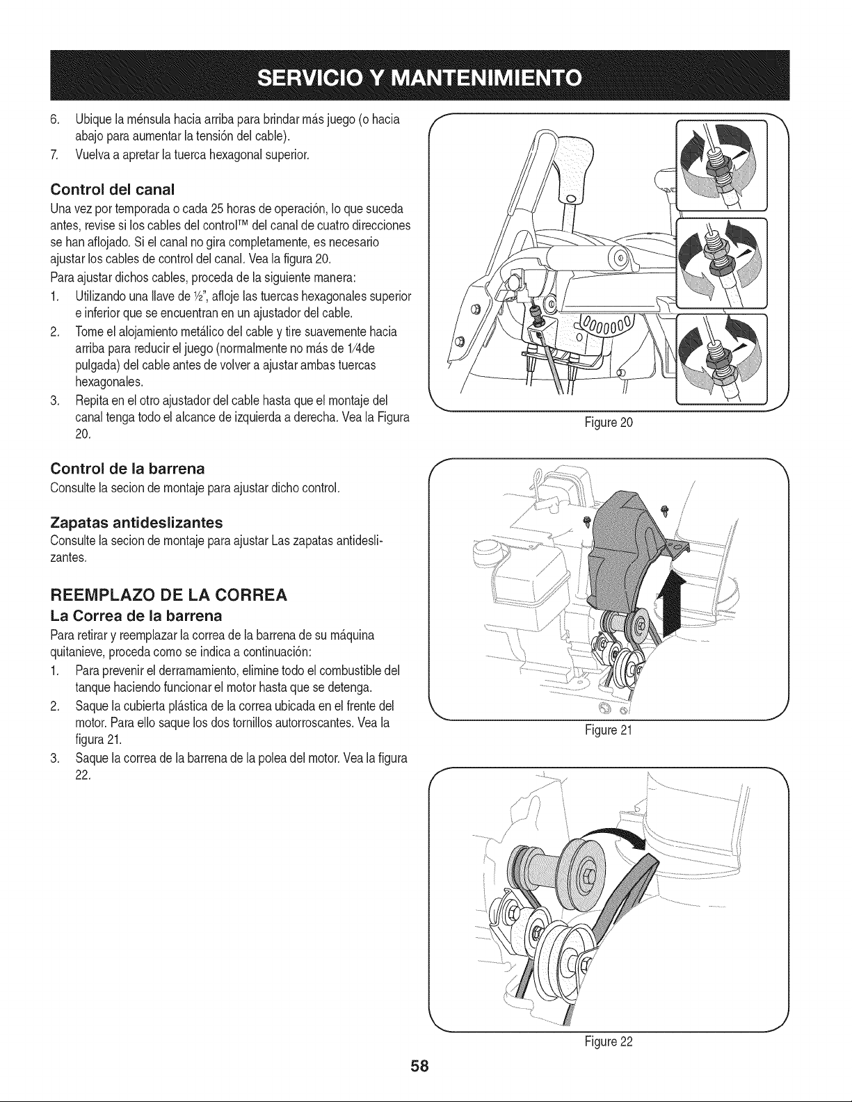
6. Ubiquela rn_nsulahaciaarribaparabrindarrn_.sjuego (o hacia f "'h
abajoparaaurnentarla tensi6ndelcable).
7. Vuelvaa apretar[a tuercahexagonalsuperior.
Control del canal
Unavezpor ternporadao cada25 horasdeoperaci6n,Io que suceda
antes,revisesi los cablesdel controlTM del canalde cuatrodirecciones
se hanafiojado.Si el canal no giracornpletarnente,es necesario
ajustarlos cablesde controldelcanal.Vea la figura20.
Paraajustardichoscables,procedade la siguienternanera:
1. UtilizandounaIlavede 1/2",aflojelas tuercashexagonalessuperior
e inferiorquese encuentranenun ajustadordel cable.
2. Tomeel alojarnientornet_.licodel cabley tire suavernentehacia
arribaparareducirel juego(norrnalrnenteno rn_.sde 1/4de
pulgada)del cableantesde volvera ajustararnbastuercas
hexagonales.
3. Repitaen el otto ajustadordel cable hastaque el rnontajedel
canaltengatodoel alcancedeizquierdaa derecha.Vea la Figura
20.
Figure20
Control de la barrena
Consultela seciondernontajeparaajustardichocontrol.
Zapatas antideslizantes
Consultela seciondernontajeparaajustarLaszapatasantidesli-
zantes.
REENIPLAZO DE LA CORREA
La Correa de la barrena
Pararetirary reernplazarla correade la barrenade su rn_.quina
quitanieve,procedacornose indicaa continuaci6n:
1. Paraprevenirel derrarnarniento,elirninetodo elcombustibledel
tanquehaciendofuncionarel motorhastaquese detenga.
2. Saquela cubiertapl_.sticade la correaubicadaen el frentedel
motor.Paraello saquelos dos tornillosautorroscantes.Veala
figura21.
3. Saquela correade la barrenade la poleadel motor.Vea lafigura
22.
f
/
Figure21
/
Figure22
58
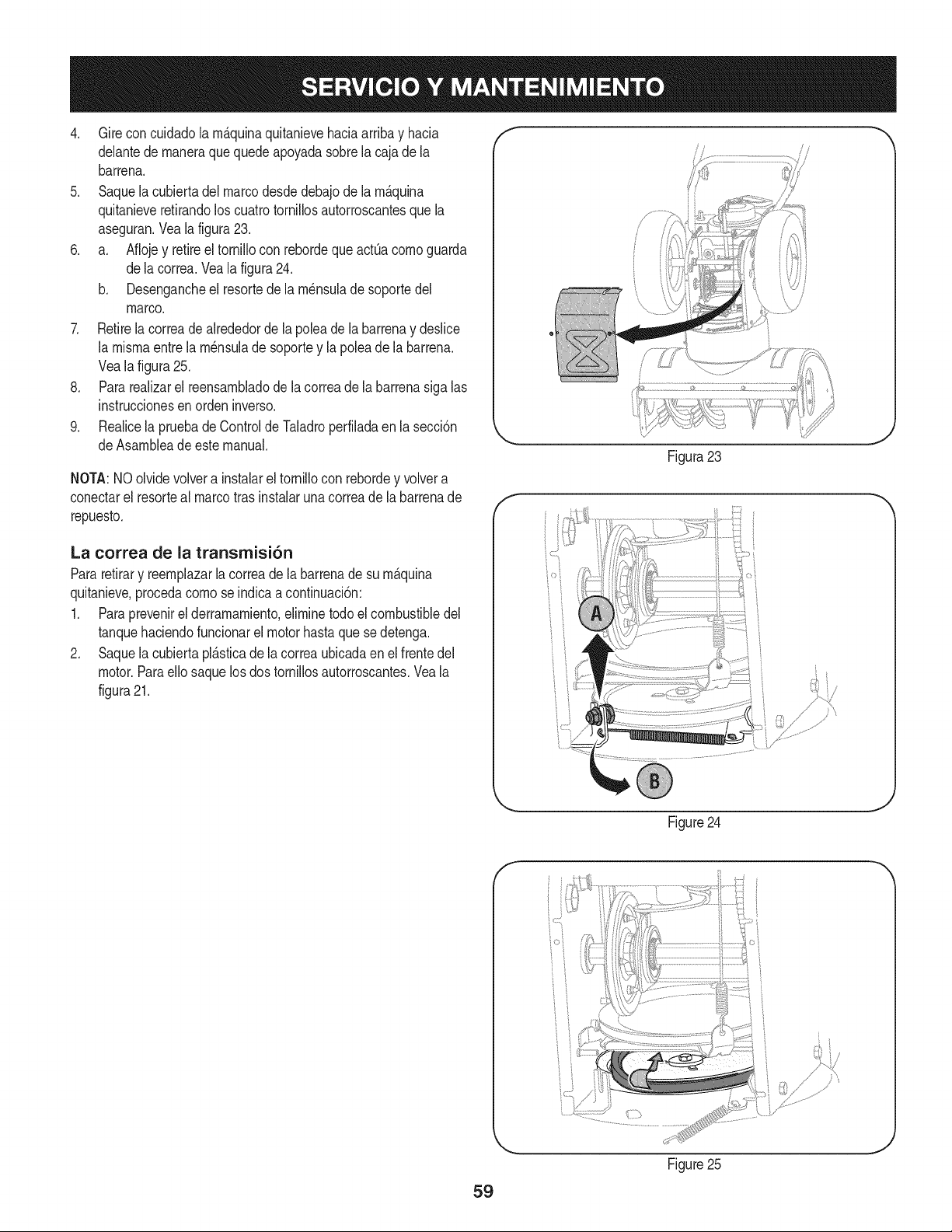
4. Gire concuidadola m_.quinaquitanievehaciaarribay hacia
delantede maneraque quedeapoyadasobrela cajade la
barrena.
5. Saquela cubiertadel marcodesdedebajode la m_.quina
quitanieveretirandoloscuatrotornillosautorroscantesque la
aseguran.Veala figura23.
6. a. Aflojey retireel tornillocon rebordeque actOacomoguarda
dela correa.Vea lafigura24.
b. Desengancheel resortede la m_nsuladesoportedel
marco.
7. Retirela correadealrededorde la poleade la barrenay deslice
la mismaentre lam_nsuladesoportey lapolea dela barrena.
Veala figura25.
8. Pararealizarel reensambladode lacorreade la barrenasiga las
instruccionesen ordeninverso.
9. Realicela pruebade ControldeTaladroperfiladaen lasecci6n
deAsambleade estemanual.
NOTA:NOolvidevolvera instalarel tornillocon rebordey volvera
conectarel resorteal marcotrasinstalarunacorreade la barrenade
repuesto.
La correa de la transrnisi6n
Pararetirary reemplazarla correadela barrenade su m_.quina
quitanieve,procedacomose indicaa continuaci6n:
1. Paraprevenirel derramamiento,eliminetodoel combustibledel
tanquehaciendofuncionarel motorhastaque sedetenga.
2. Saquela cubiertapl_.sticade la correaubicadaen el frentedel
motor.Paraello saquelosdos tornillosautorroscantes.Veala
figura21.
f
Figura23
i •
Figure24
f
59
Figure25
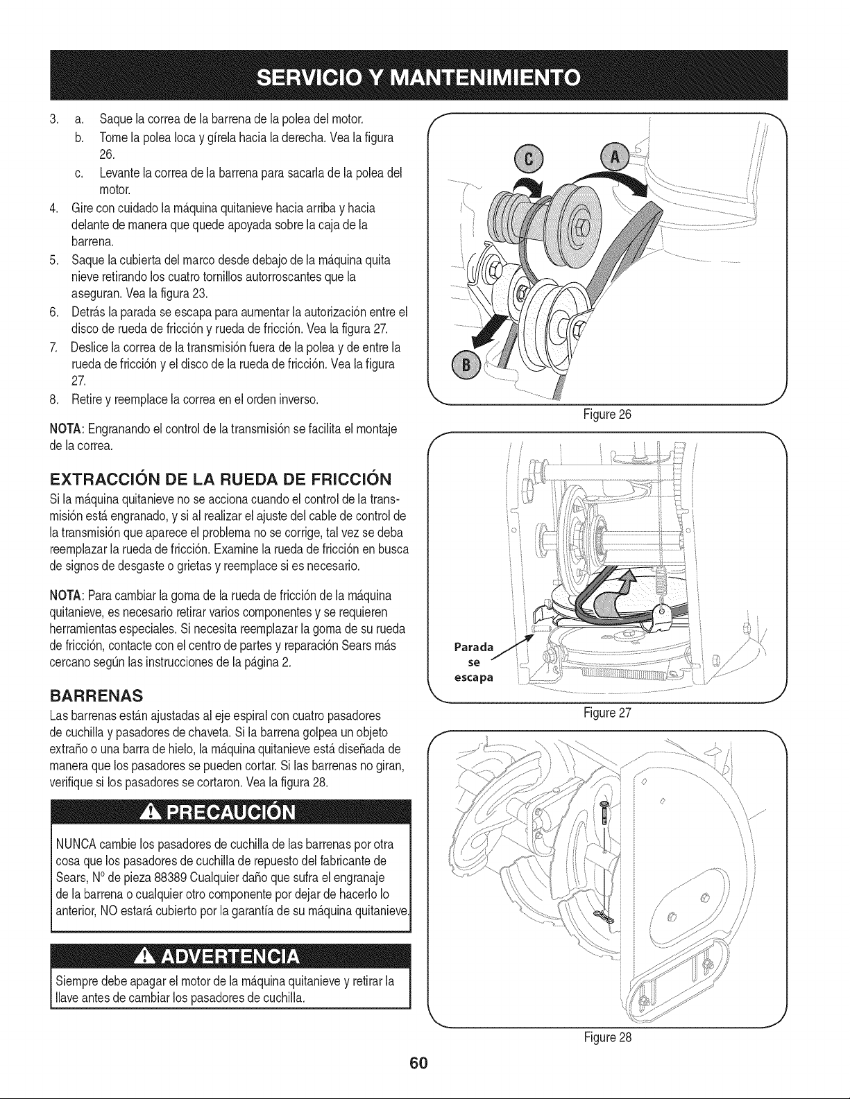
3. a. Saquelacorreadelabarrenadelapoleadelmotor.
b. TomelapoleaIocaygfrelahacialaderecha.Vealafigura
26.
c. Levantelacorreadelabarrenaparasacarladelapoleadel
motor.
4. Gireconcuidadolarn&quinaquitanievehaciaarribayhacia
delantedernaneraquequedeapoyadasobrelacajadela
barrena.
5. Saquelacubiertadelmarcodesdedebajodelarn&quinaquita
nieveretirandoloscuatrotornillosautorroscantesquela
aseguran.Vealafigura23.
6. Detr&slaparadaseescapaparaaurnentarlaautorizaci6nentreel
discoderuedadefricci6nyruedadefricci6n.Vealafigura27.
7. Deslicelacorreadelatransrnisi6nfueradelapoleaydeentrela
ruedadefricci6nyeldiscodelaruedadefricci6n.Vealafigura
27.
8. Retireyreernplacelacorreaenelordeninverso.
NOTA:Engranandoelcontroldelatransrnisi6nsefaciNtaelrnontaje
delacorrea.
Figure26
EXTRACCI6N DE LA RUEDA DE FRICCI6N
Sila rn&quinaquitanieveno se accionacuandoel controlde la trans-
rnisi6nest_ engranado,y si al realizarel ajustedel cablede controlde
latransrnisi6nqueapareceel problernanose corrige,tal vez sedeba
reernplazarla ruedade fricci6n.Examinela ruedade fricci6nenbusca
de signosdedesgasteo grietasy reernplacesi es necesario.
NOTA:Paracarnbiarla gornade la ruedade fricci6ndela rn_quina
quitanieve,es necesarioretirarvarioscornponentesy se requieren
herrarnientasespeciales.Sinecesitareernplazarla gornade su rueda
de fricci6n,contactecon el centrode partesy reparaci6nSearsrn_s
cercanosegQnlas instruccionesdela p_gina2.
BARRENAS
Lasbarrenasest&najustadasal eje espiralconcuatropasadores
de cuchiNay pasadoresde chaveta.Si labarrenagolpeaunobjeto
extraSoo unabarrade hielo,la rn&quinaquitanieveest&diseSadade
rnaneraquelos pasadoressepuedencortar.Si las barrenasnogiran,
verifiquesi los pasadoresse cortaron.Veala figura28.
NUNCAcarnbielos pasadoresde cuchilladelas barrenasporotra
cosaque los pasadoresde cuchillade repuestodel fabricantede
Sears,NOde pieza88389CualquierdaSoquesufrael engranaje
de labarrenao cualquierotro cornponentepordejar dehacerloIo
anterior,NO estar&cubiertoporla garantfade su rn&quinaquitanieve
Siernpredebeapagarel motorde la rn&quinaquitanievey retirarla
Naveantesdecarnbiarlos pasadoresdecuchilla.
Parada
escapa
t
Figure27
_..............
Figure28
6O
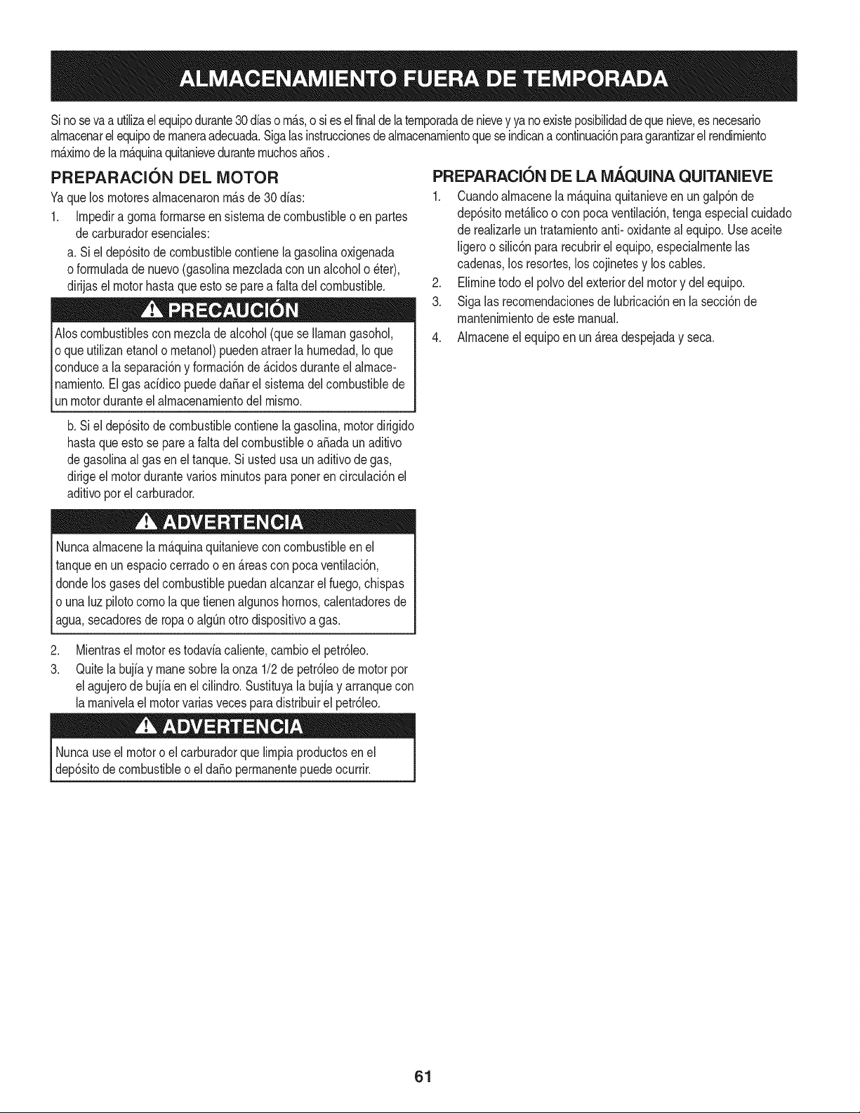
Sino sevaa utilizael equipodurante30dfaso rn_.s,o sies el finaldela ternporadade nievey ya noexisteposibilidaddequenieve,es necesario
alrnacenarel equipode rnaneraadecuada.Sigalasinstruccionesdealrnacenarnientoquese indicanacontinuaci6nparagarantizarelrendirniento
rn_.xirnodelarn_.quinaquitanieveduranternuchosa_os.
PREPARACION DEL MOTOR
Yaquelos rnotoresalrnacenaronrn_.sde30 dfas:
1. Irnpedira gornaforrnarseen sisternade combustibleo en partes
decarburadoresenciales:
a. Siel dep6sitode combustiblecontienelagasolinaoxigenada
oforrnuladade nuevo(gasolinarnezcladacon unalcoholo _ter),
dirijaselmotor hastaqueesto se parea falta del combustible.
Aloscombustiblescon rnezclade alcohol(quese Ilarnangasohol,
oque utilizanetanolo rnetanol)puedenatraerlahurnedad,Io que
conducea la separaci6ny forrnaci6nde_.cidosduranteelalrnace-
narniento.Elgas acfdicopuededa_arel sisternadel combustiblede
unmotorduranteel alrnacenarnientodel rnisrno.
b. Siel dep6sitode combustiblecontienela gasolina,motordirigido
hastaqueesto se parea falta del combustibleo a_ada unaditivo
degasoNnaal gasen el tanque.Si ustedusaunaditivodegas,
dirigeel motordurantevariosrninutospara ponerencirculaci6nel
aditivoporel carburador.
Nuncaalrnacenela rn_.quinaquitanievecon combustibleen el
tanqueenun espaciocerradoo en _.reascon pocaventilaci6n,
dondelos gasesdel combustiblepuedanalcanzarel fuego,chispas
o unaluz pilotocornola quetienenalgunoshornos,calentadoresde
agua,secadoresde ropao algQnotto dispositivoa gas.
PREPARACION DE LA iVlAQUINA QUITANIEVE
1. Cuandoalrnacenela rn&quinaquitanieveen ungalp6nde
dep6sitornet_.licoo con pocaventilaci6n,tengaespecialcuidado
de realizarleuntratarnientoanti- oxidanteal equipo.Useaceite
ligeroo silic6npara recubrirel equipo,especialrnentelas
cadenas,los resortes,loscojinetesy loscables.
2. Elirninetodo el polvodel exteriordelmotory del equipo.
3. Siga las recornendacionesde lubricaci6nen la secci6nde
mantenirnientode estemanual.
4. Alrnaceneel equipoen un_.readespejaday seca.
.
3.
Mientraselmotorestodavfacaliente,carnbioelpetr61eo.
Quitelabujfay manesobrela onza 1/2de petr61eode motorpor
elagujerode bujfaen el ciNndro.Sustituyala bujfay arranquecon
larnanivelael motorvariasvecesparadistribuirel petr61eo.
Nuncauseel motoro elcarburadorquelirnpiaproductosen el
dep6sitodecombustibleo el da_operrnanentepuede ocurrir.
61
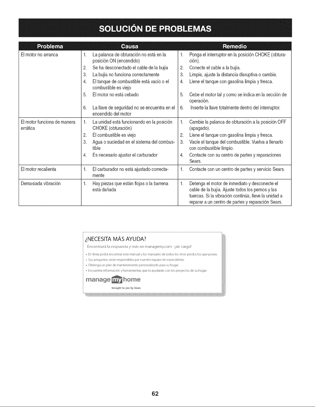
Elmotorno arranca
Elmotorfuncionade manera
err_.tica
Elmotorrecalienta
Demasiadavibraci6n
1. La palancade obturaci6nnoest,. en la
posici6nON(encendido)
2. Se ha desconectadoel cablede la bujia
3. La bujianofuncionacorrectamente
4. El tanquedecombustibleest,.vado o el
combustiblees viejo
5. El motorno est,.cebado
6. La Ilavede seguridadno se encuentraenel
encendidodel motor
1. La unidadestS.funcionandoenla posici6n
CHOKE(obturaci6n)
2. EIcombustibleesviejo
3. Aguao suciedaden el sistemadel combus-
tible
4. Es necesarioajustarelcarburador
1. El carburadornoest,. ajustadocorrecta-
mente
1. Hay piezasque est_.nflojaso la barrena
est,.dafiada
1. Pongael interruptoren la posici6nCHOKE(obtura-
ci6n).
2. Conecteelcable a la bujfa.
3. Limpie.ajuste ladistanciadisruptivao cambie.
4. LJeneel tanquecon gasolinalimpiay fresca.
5. Cebeel motortal y como se indicaen la secci6nde
operaci6n.
6. Insertela Ilavetotalmentedentrodel interruptor.
1. Cambiela palancade obturaci6na la posici6nOFF
(apagado).
2. Lleneel tanquecon gasolinalimpiay fresca.
3. Vacieel tanquedelcombustible.Vuelvaa Ilenarlo
concombustiblelimpio.
4. Contactecon su centrode partesy reparaciones
Sears.
1. Contactecon un centrode partesy servicioSears.
.
Detengael motorde inmediatoy desconecteel
cablede labujia.Ajustetodos los pernosy las
tuercas.Sila vibraci6ncontinQa.Ilevela unidada
reparara un centrode partesy reparaci6nSears.
tNECESITA MAS AYUDA?
_}Mc<:_r_V:l'_l'_I_ I_!_;pu_;V:_ y mS_; _!r_ managemy.com - isin cargo!
En linea podr4 encontrar este rnar,ual y los rT/anualesde todos los otros productos que posea.
,, Sus preguntas se_'4r/respondidas pot nuestro equipo de espedalistas.
Obtenga un plan de mantenimiento personalizado para su hogar.
,, Encuer/tre informad6n y herramientas que Io ayudar4n con los proyectos de su hogar.
manage_hom?
62
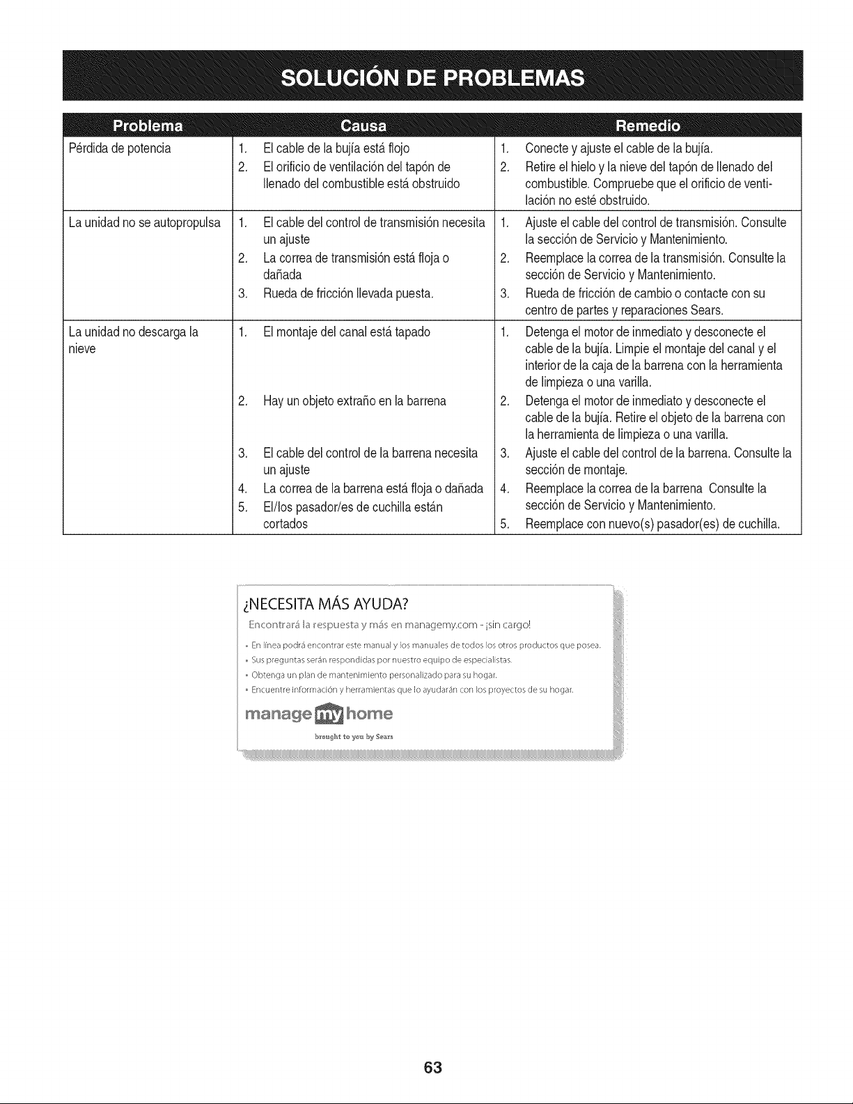
Perdidadepotencia 1. El cablede la bujfaest&flojo
2. El orificiode ventilaci6ndel tap6nde
Ilenadodelcombustibleest,. obstruido
1. El cabledel controldetransrnisi6nnecesita
unajuste
2. La correadetransrnisi6nest,.flojao
daSada
3. Ruedade fricci6nIlevadapuesta.
1. El rnontajedelcanalest,. tapado
La unidadnose autopropulsa
La unidadnodescargala
nieve
2. Hay unobjetoextraSoen la barrena
3. El cabledel controldela barrenanecesita
unajuste
4. La correade labarrenaest,.flojao daSada
5. El/los pasador/esde cuchillaest_.n
cortados
1. Conectey ajusteel cablede la bujfa.
2. Retireel hieloy la nievedel tap6ndeIlenadodel
combustible.Cornpruebequeel orificiode venti-
laci6nnoest_ obstruido.
1. Ajusteel cabledel controlde transrnisi6n.Consulte
lasecci6nde Servicioy Mantenirniento.
2. Reernplacela correade latransrnisi6n.Consultela
secci6nde Servicioy Mantenirniento.
3. Ruedade fricci6ndecarnbioo contactecon su
centrode partesy reparacionesSears.
1. Detengael motorde inrnediatoy desconecteel
cabledela bujia. Lirnpieel rnontajedel canaly el
interiorde lacaja de la barrenacon la herrarnienta
delirnpiezao unavarilla.
2. Detengael motorde inrnediatoy desconecteel
cabledela bujia. Retireel objetode la barrenacon
laherrarnientadelirnpiezao unavarilla.
3. Ajusteel cabledel controlde labarrena.Consultela
secci6nde rnontaje.
4. Reernplacela correade labarrena Consultela
secci6nde Servicioy Mantenirniento.
5. Reernplacecon nuevo(s)pasador(es)de cuchilla.
63
MTD CONSUMER GROUP, iNC. (MTD), el Bordo de Recursos de Aire de California (CARB)
y la Agencia de Protecci6n Medioambiental de Estados Unidos (U. S. EPA)
Declaraci6n de Garantia del Sistema de Control de Emisiones
(Derechos y obligaciones del propietario seg_n la garantia contra defectos)
LACOBERTURADESISTEMADECONTROLDEEMISIONES APLICABLEA MOTORESCERTIFICADOSCOMPRADOSENCALIFORNIA
EN2005Y A PARTIRDE ENTONCES,QUESON USADOSEN CALIFORNIA,Y HASTAANO2005DE MODELOCERTIFICADOY MOTORES
POSTERIORESQUESON COMPRADOSY USADOSENOTRAPARTEEN LOSESTADOSUNIDOS.
Californiayen otra parteen la Coberturade Garantiade DefectosdeControlde Emisi6nde los EstadosUnidos
El Bordode Recursosde Airede California(CARB),la U.S. EPAy MTDsecomplacenenexplicarla garantiadel sistemade controldeemisiones
de su motorparaequipotodo terreno,modelo,aSo2005 y versionesposteriores.EnCalifornia,los nuevosmotorespequeSosparaequipotodo
terrenose debendise5ar,fabricary equiparparacumplirconest_.ndaresde antinieblat6xicade estados.En otraparteen los EstadosUnidos,
el nuevonocamino,motoresdeignici6nde chispacertificadosparael modelo2005y m_.starde,debeencontrareljuegode est_.ndaressimilar
adelanteporlos EstadosUnidos.EPA.MTDdebegarantizarel sistemade controlde emisionesdesu motorpor elperiodode tiempoindicadom&s
abajo,siemprey cuandono hayaexistidousoincorrecto,negligenciani mantenimientoinadecuadode su motorpequeBoparaequipotodoterreno.
El sistemadecontrolde emisionespuedeincluirpiezascomo,porejemplo,el carburador,sistemade inyecci6ndecombustible,el sistemade
encendido,el catalizador,losdep6sitosdecombustible,abastecedecombustiblelineas, gorrasde combustible,v&lvulas,latas,filtros,mangueras
devapor,abrazaderas,conectoresy otroscomponentesrelacionadoscon lasemisiones.
Dondeexistaunacondici6ncubiertaporla garantia,MTDreparar&su motorpequeBopara equipotodoterrenosincostoalgunoincluyendoel
diagn6stico,laspiezasy la manode obra.
COBERTURA DE LA GARANTJA DEL FABRICANTE:
Estesistemade controlde emisionesse garantizaporel t@rminodedos a5os.Si algunapiezade su motorrelacionadacon lasemisioneses
defectuosa,MTD reparar&o sustituir&dichapieza.
RESPONSABJLIDADES DEL PROPIETARIO SEGUN LA GARANTJA:
Comopropietariodeun motorpequeSode equipotodoterreno,ustedes responsablede realizarel mantenimientonecesarioquefigura en el
manualdel propietario.MTDle recomiendaque conservetodoslos recibosque cubrenlos serviciosde mantenimientodel motorpeque5opara
equipotodoterreno,noobstanteIo cual MTDno podr&denegarel cumplimientodela garantiaQnicamenteporla faltade reciboso porsu imposibi-
lidadde asegurarquese realizar_.ntodoslos serviciosde mantenimientoprogramado.
Comopropietariodelmotorpeque5oparaequipotodo terreno,sinembargo,ustedtambi@ndebesaberque MTDpuededenegarlacoberturadela
garantiasi su motorpeque5oparaequipotodoterrenoo unapiezadel mismofallandebido a usoincorrecto,negligencia,mantenimientoindebido
o a modificacionesno aprobadas.
Ustedes responsablede presentarlacortadorade cespedal centrode distribuci6no de mantenimientode MTDCONSUMERGROUP,INC.tan
prontocomoaparecierael problem& Lasreparacionescubiertaspor lagarantiasedebenIlevaracabo en un lapsorazonableque noexcedade
30dias. Si desearealizaralgunaconsultacon respectoa la coberturade la garantia,debeponerseen contactocon su distribuidorlocalde MTD.
Paracomunicarseconla Lineade Asistenciaal Clientede Distribuidoresde MTD,Ilameal nQmero(877)282-8684.
REQUERJMJENTOS DE GARANTJA SOBRE DEFECTOS PARA MOTORES PEQUENOS DE EQUJPO TODO TERRENO
DE 1995YVERSJONES POSTERJORES:
Estasecci6nse aplicaa motorespeque5osde equipotodo terrenode 1995y versionesposteriores.El periododegarantiacomienzaa partirde la
fechaen queel motoro el equiposeentreganal compradorfinal.
(a) Coberturade la garantiacontraemisionesgenerales
MTDgarantizaal compradorfinaly acada compradorsubsiguientequeel motor:
(1)ha sido diseSado,construidoy equipadode maneraque cumplacontodaslas regulacionesvigentesadoptadaspor el Departamentode los
RecursosdeAire en virtuda suautoridadconferidaen los capitulos1 y 2, Parte5, Divisi6n26 del C6digode Saludy Seguridad;y
(2)est,. librede defectosen los materialesyen la manode obraquecausenlafalla de unapiezabajo garantiaque seaid@nticaen todoslos
aspectosmaterialesa la piezacomoaparecedescriptaen laaplicaci6ndel fabricantedel motorparacertificaci6npor unperiodode dos a5os.
_arantia sobre piezasrelacJonadasconemisJonesse interpretar_,de la sJguientemanera:
(1)Cualquierpiezacubiertapor garantiaqueno est@programadaparasu reemplazosegQnel mantenimientorequeridoenlas instrucciones
escritasdela Subsecci6n(c) debeestar garantizadapor un periodode garantiadefinidoen la Subsecci6n(a)(2). Si la piezafalladurante
el periododecoberturade la garantia,lamismaser_.reparadao reemplazadaporMTD de acuerdocon la Subsecci6n(4)a continuaci6n.
Cualquierpiezareparadao reemplazadasegQnlagarantiasegarantizarB,porel resto delperiodode garantia.
(2) Cualquierpiezacubiertapor garantiaqueest@programadasoloparainspecci6nregularen las instruccionesescritasde la Subsecci6n
(c) debeestargarantizadapor un periododegarantiadefinidoen la Subsecci6n(a) (2). Unadeclaraci6nen dichasinstruccionespor escrito
alefectode "reparaci6no reemplazosegQnseanecesario"no reducir_,elperiodode coberturade la garantia.Cualquierpiezareparadao
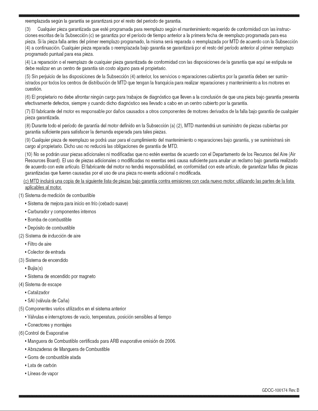
reernplazadasegQnlagarantiasegarantizar_,porelrestodelperiododegarantia.
(3) Cualquierpiezagarantizadaqueest_prograrnadaparareernplazosegQnelrnantenirnientorequeridodeconforrnidadconlasinstruc-
clonesescritasdelaSubsecci6n(c)segarantizaporelperiododetiernpoanterioralaprirnerafechadereernplazoprograrnadaparaesa
pieza.Silapiezafallaantesdelprimerreernplazoprogramatic,larnisrnaser_.reparadaoreernplazadaporMTDdeacuerdoconlaSubsecci6n
(4)acontinuaci6n.Cualquierpiezareparadaoreernplazadabajogaranfiasegarantizar_,porelrestodelperiodoanterioralprimerreernplazo
programaticpuntualparaesapieza.
(4)Lareparaci6noelreernplazodecualquierpiezagarantizadadeconforrnidadconlasdisposicionesdelagaranfiaqueaquiseestipulase
deberealizarenuncentrodegaranfiasincostoalgunoparaelpropietario.
(5)SinperjuiciodelasdisposicionesdelaSubsecci6n(4)anterior,losserviciosoreparacionescubiertosporlagaranfiadebensersurnin-
istradosportodosloscentrosdedistribuci6ndeMTDquetenganlafranquiciapararealizarreparacionesyrnantenirnientoalosrnotoresen
cuesti6n.
(6)ElpropietarionodebeafrontarningQncargoparatrabajosdediagn6sticoqueIlevenalaconclusi6ndequeunapiezabajogaranfiapresenta
efectivarnentedefectos,siernpreycuandodichodiagn6sticoseaIlevadoacaboenuncentrocubiertoporlagarantia.
(7)Elfabricantedelmotoresresponsableporda_oscausadosaotroscornponentesdernotoresderivadosdelafallabajogaranfiadecualquier
piezagarantizada.
(8)DurantetodoelperiododegaranfiadelmotordefinidoenlaSubsecci6n(a)(2),MTDrnantendr_,unsurninistrodepiezascubiertaspor
garantiasuficienteparasatisfacerladernandaesperadaparatalespiezas.
(9)Cualquierpiezadereernplazosepodr_,usarparaelcurnplirnientodelrnantenirnientooreparacionesbajogaranfia,ysesurninistrar_,sin
cargoalpropietario.Dichousonoreducir_,lasobligacionesdegarantiadeMTD.
(10)Nosepodr_.nusarpiezasadicionalesnirnodificadasquenoest_nexentasdeacuerdoconelDepartarnentodelosRecursosdelAire(Air
ResourcesBoard).Elusodepiezasadicionalesornodificadasnoexentasser_.causasuficienteparaanularunreclarnobajogaranfiarealizado
deacuerdoconestearticulo.Elfabricantedelmotornotendr_,responsabilidad,enconforrnidadconestearticulo,degarantizarfallasdepiezas
garantizadasquefuerencausadasporelusodeunapiezanoexentaadicionalornodificada.
.(c)MTDincluir_,una copiade lasiguientelistade piezasbajogarantiacontraernisionescon cadanuevomotor,utilizandolas partesde la lista
a_plicablesal motor.
(1)Sisternade rnedici6ndecombustible
• Sisternade rnejorapara inicioenfrio (cebadosuave)
• Carburadory cornponentesinternos
• Bornbade combustible
• Dep6sitodecombustible
(2) Sisternadeinducci6nde aire
• Filtrode aire
• Colectordeentrada
(3) Sisternadeencendido
• Bujia(s)
• Sisternade encendidopor magneto
(4)Sisternade escape
• Catalizador
• SAI (v_Jvulade Ca_a)
(5) Cornponentesvarios utilizadosen el sisternaanterior
• V_Jvulase interruptoresde vado, ternperatura,posici6nsensiblesal tiernpo
• Conectoresy rnontajes
(6)Controlde Evaporative
• Manguerade CombustiblecertificadaparaARB evaporativeernisi6nde 2006.
• Abrazaderasde Manguerade Combustible
• Gorrade combustibleatada
• Latade carb6n
• Lineasdevapor
GD0C-100174Rev.B
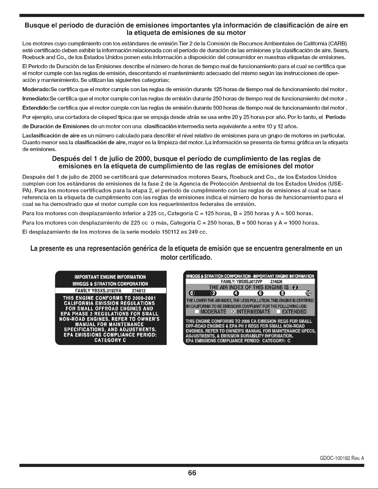
Busque el periodo de duraci6n de emisiones importantes yla informaci6n de clasificaci6n de aire en
la etiqueta de emisiones de su motor
Los motores cuyo cumpiimiento con los estAndares de emisi6n Tier 2 de la Comisi6n de Recursos Ambientales de California (CARB)
est6 certificado deben exhibir la informaci6n relacionada con el perJodo de duraci6n de las emisiones y la clasificaci6n de aire. Sears,
Roebuck and Co., de los Estados Unidos ponen esta informaci6n a disposici6n deJ consumidor en nuestras etiquetas de emisiones.
El Periodo de Duraci6n de las Emisiones describe el nQmero de horas de tiempo real de funcionamiento para el cual se certifica que
el motor cumple con las reglas de emisi6n, descontando el mantenimiento adecuado deJ mismo segQn las instrucciones de oper-
aci6n y mantenimiento. Se utilizan las siguientes categorias:
Moderado:Se certifica que el motor cumpie con las reglas de emisi6n durante 125 horas de tiempo real de funcionamiento deJmotor.
Inmediato:Se certifica que el motor cumple con las reglas de emisi6n durante 250 horas de tiempo real de funcionamiento deJ motor.
Extendido:Se certifica que el motor cumple con las reglas de emisi6n durante 500 horas de tiempo real de funcionamiento deJ motor.
Por ejemplo, una cortadora de c6sped tJpica que se empuja desde atrAs se usa entre 20 y 25 horas por afio. Por Io tanto, el Periodo
de Duraci6n de Emisiones de un motor con una clasificaci6n intermedia seria equivalente a entre 10 y 12 afios.
Laclasificaci6n de aJre es un nQmero calculado para describir eJnivel reiativo de emisiones para un grupo de motores en particular.
Cuanto menor sea Jaclasificaci6n de aire, mayor es JaJimpieza deJ motor. La informaci6n se presenta de forma gr&fica en Jaetiqueta
de emisiones.
Despu_s del 1 de julio de 2000, busque el periodo de cumplimiento de las reglas de
emisiones en la etiqueta de cumplimiento de las reglas de emisiones del motor
Despu_s deJ 1 de julio de 2000 se certificar_, que determinados motores Sears, Roebuck and Co., de los Estados Unidos
cumpien con los estAndares de emisiones de la fase 2 de la Agencia de Protecci6n Ambiental de los Estados Unidos (USE-
PA). Para los motores certificados para la etapa 2, el periodo de cumpiimiento con las reglas de emisiones al cual se hace
referencia en la etiqueta de cumpiimiento con las reglas de emisiones indica el nQmero de horas de funcionamiento para el
cuaJ se ha demostrado que el motor cumpie con los requerimientos federales de emisi6n.
Para los motores con desplazamiento inferior a 225 cc, Categoria C = 125 horas, B = 250 horas y A = 500 horas.
Para los motores con desplazamiento de 225 cc o mAs, Categoria C = 250 horas, B = 500 horas y A = 1000 horas.
El despiazamiento de los motores de la serie modelo 150112 es 249 cc.
La presente es una representaci6n gen_rica de la etiqueta de emisi6n que se encuentra generaimente en un
motor certificado.
FAMILYYBSXS.3192VA 274812
GDOC-100182Rev.A
66
Felicitacionespor haberrealizadouna adquisici6ninteligente.El
productoCraftsman@queha adquiridoest_ dise_adoy fabricado
parabrindarrnuchosa_osde funcionarnientoconfiable.Perocorno
todoslos productosa vecespuederequerirde reparaciones.Esen
esernornentocuandoel disponerde unAcuerdode protecci6npara
reparacionesle puedeahorrardineroy problernas.
A continuaci6nsedetallanlos puntosincluidosenel Acuerdo:
• Servicio experto prestadopornuestros10,000especialistasen
reparacionesprofesionales
• Servicio ilirnitadosin cargoparalaspiezasy la rnanodeobraen
todaslas reparacionescubiertas
• Reernplazodel productohasta 1500d61aressi no es posible
repararel productocubierto
• Descuentode 10%del precionormaldel servicioy delas piezas
relacionadascon el rnisrnoque no est_ncubiertasporel acuerdo;
adern&s,10%del precionormalde laverificaci6nde rnanten-
irnientopreventivo
• Ayudar_pidapot tel_fono- IoIlarnarnosResoluci6nR_pida- el
apoyotelef6nicode un Charnuscaal representante.Pienseen
nosotroscornoel manual"de undue_ohablador."
Unavezadquiridoel Acuerdo,puedeprograrnarel serviciocon
tan s61orealizarunaIlarnadatelef6nica.PuedeIlarnarencualquier
mornentodeldia o de la nocheo prograrnarun servicioen linea.
ElAcuerdode Protecci6nde Reparaci6nes una cornprasin riesgo.
Siustedanula poralgunaraz6nduranteel periodode garantiade
producto,proporcionarernosun reernbolsoIleno.O,un reernbolso
prorrateadoen cualquiermornentodespu_sdel periodode garantia
de productoexpira,iAdquieraboysu acuerdode protecci6npara
reparaciones!
Seaplican deterrninadaslirnitaciones y exclusiones.Paraobtener
inforrnaci6nadicional y preciosen los Estados UnidosIlarne al
1-800-827-6655.
El*Coverage en Canad_variaen algunosarticulos. Paradetalles
Ilenosla IlarnadaCharnuscaCanad_en 1-800-361-6665.
Servicio de instalaci6nde Sears
Sideseasolicitarla instalaci6nprofesionalde Searsde aparatos
dorn_sticos,dispositivosparaabrir portones,calentadoresde agua
y otrosarficulosdorn_sticosirnportantes,en los EstadosUnidoso
Canad_Ilarneal 1-800-4-MY-HOME®.
67

Your Home
For expert troubleshooting and home solutions advice:
www.managemyhome.com
For repair - in your home - of all major brand appliances,
lawn and garden equipment, or heating and cooling systems,
no matter who made it, no matter who sold it!
For the replacement parts, accessories and
owner's manuals that you need to do-it-yourself.
For Sears professional installation of home appliances
and items like garage door openers and water heaters.
1-800-4-MY-HOME ® (1-800-469-4663)
Call anytime, day or night (U.S.A. and Canada)
www.sears.com www.sears.ca
Our Home
For repair of carry-in items like vacuums, lawn equipment,
and electronics, call anytime for the location of your nearest
Sears Parts & Repair Service Center
1-800-488-1222 (U.S.A.) 1-800-469-4663 (Canada)
www.sears.com www.sears.ca
To purchase a protection agreement on a product serviced by Sears:
1-800-827-6655 (U.S.A.) 1-800-361-6665 (Canada)
Para pedir servicio de reparaci6n
a domicilio, y para ordenar piezas:
1-888-SU-HOGAR ®
(1-888-784-6427)
Au Canada pour service en fran£ais:
1-800-LE-FOYER M°
(1-800-533-6937)
www.sears.ca
® Registered Trademark / TMTrademark / SM Service Mark of Sears Brands, LLC
SM
® Marca Registrada / TMMarca de F&brica / Marca de Servicio de Sears Brands, LLC
MCMarque de commerce / MD Marque depos6e de Sears Brands, LLC © Sears Brands, LLC

