perator s
PROFESSIONAL
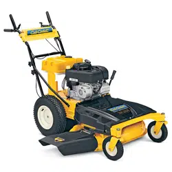
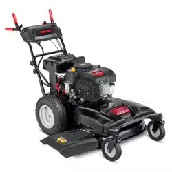
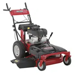
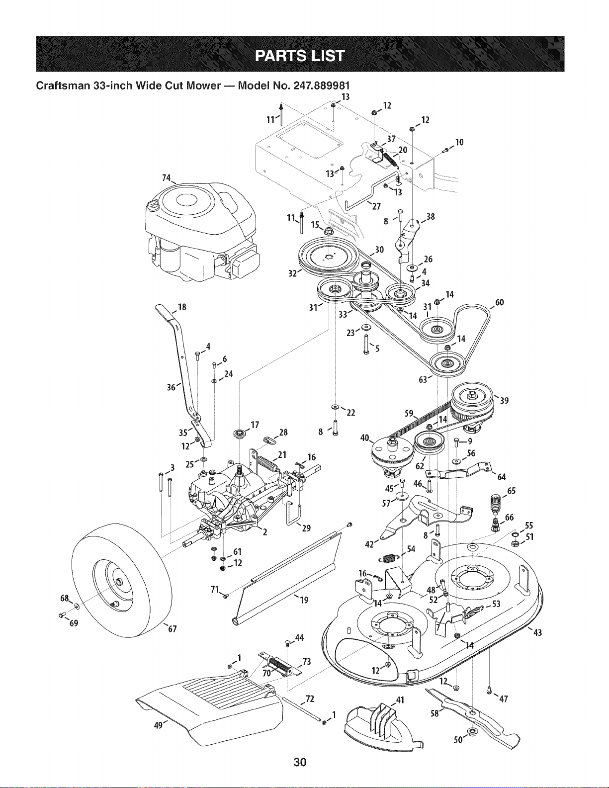
33-inch Wide Cut Mower
Model No. 247.889981
CAUTION: Before using this
product, read this manual and
follow all safety rules and operating
instructions.
o SAFETY
ASSEMBLY
OPERATION
MAINTENANCE
PARTS LIST
ESPANOL R 49
Sears Brands Management Corporation, Hoffman Estates, IL 60179, U.S.A.
Visit our website: www.craftsman.com FormNo.769-06544B
(January13,2012)
Warranty Statement .......................................................... 2
Safety instructions ........................................................ 3-6
Slope Guide ....................................................................... 7
Assembly ...................................................................... 8-12
Operation ................................................................... 13-15
Service and Maintenance ......................................... 16-25
Off-Season Storage ........................................................ 26
Troubleshooting .............................................................. 27
Parts List ................................................................... 28-42
Espa_ol ............................................................................ 49
Service Numbers ............................................. Back Cover
CRAFTSMAN PROFESSIONAL TWO YEAR FULL WARRANTY
FORTWOYEARSfromthe dateof purchase,this productis warrantedagainstanydefectsin materialor workmanship.Defectiveproductwill
receivefree repairor free replacementif repairis unavailable.
Thiswarrantyappliesfor onlyone yearfromthe dateof purchaseif this productis everusedwhileprovidingcommercialservicesor if rentedto
anotherperson.
For warranty coveragedetails to obtain repairor replacement,visit the website: www.craftsman.com.
This warranty covers ONLYdefects in material andworkmanship. Warranty coverage does NOTinclude:
• Expendableitemsthatbecomewornduringnormaluse,includingbutnot limitedto blades,sparkplugs,aircleaners,belts,andoil filters.
• Standardmaintenanceservicing,oilchanges,or tune-ups.
• Tire replacementor repaircausedby puncturesfromoutsideobjects,suchas nails,thorns,stumps,or glass.
• Tireor wheelreplacementor repairresultingfromnormalwear,accident,orimproperoperationor maintenance.
• Repairsnecessarybecauseof operatorabuse,includingbutnot limitedto damagecausedby impactingobjectsthat bendthe frameor
crankshaft,orover-speedingtheengine.
• Repairsnecessarybecauseof operatornegligence,includingbut not limitedto,electricalandmechanicaldamagecausedby improper
storage,failureto usethe propergradeandamountof engineoil, failureto keepthe deckclearof flammabledebris,orfailureto maintainthe
equipmentaccordingto the instructionscontainedinthe operator'smanual.
• Engine(fuelsystem)cleaningor repairscausedbyfuel determinedto becontaminatedoroxidized(stale).In general,fuel shouldbeused
within30 daysof itspurchasedate.
• Normaldeteriorationandwearof the exteriorfinishes,or productlabelreplacement.
Thiswarrantygivesyou specificlegalrights,andyou mayalso haveotherrightswhichvaryfromstateto state.
Sears Brands ManagementCorporation, Hoffman Estates, IL 60179
GrossHP: 12.5
EngineOil: SAE30
Fuel: UnleadedGasoline
SparkPlug: Champion®RC12YC
Engine: Briggs& StrattonPowerBuiltTM
ModelNumber
Serial Number
Dateof Purchase
Recordthe modelnumber,serialnumber,
anddateof purchaseabove.
© SearsBrands,LLC 2
Thissymbolpointsout importantsafetyinstructionswhich,if not
followed,couldendangerthepersonalsafetyand/orpropertyof
yourselfandothers. Readandfollowall instructionsin thismanual
beforeattemptingto operatethismachine.Failureto complywith
theseinstructionsmayresultin personalinjury.Whenyou seethis
symbol,HEEDITSWARNING!
CALIFORNIA PROPOSITION 65
EngineExhaust,someof itsconstituents,andcertainvehicle
componentscontainoremitchemicalsknownto Stateof California
to causecancerandbirthdefectsorother reproductiveharm.
Batteryposts,terminals,and relatedaccessoriescontainleadand
leadcompounds,chemicalsknownto the Stateof Californiato
causecancerandreproductiveharm.Washhandsafterhandling.
Thismachinewasbuiltto beoperatedaccordingto the safeopera-
tion practicesinthis manual.As withanytypeof powerequipment,
carelessnessorerroron the partof the operatorcan resultin serious
injury.Thismachineis capableof amputatingfingers,hands,toes
andfeetandthrowingdebris.Failureto observethe followingsafety
instructionscouldresultin seriousinjuryor death.
Your Responsibility--Restrictthe use of thispowermachineto
personswho read,understandandfollowthewarningsand instruc-
tionsin thismanualandon the machine.
SAVE THESE INSTRUCTIONS!
GENERAL OPERATION
* Readthisoperator'smanual carefullyin its entiretybefore
attemptingto assemblethis machine.Read,understand,and
followall instructionsonthe machineandinthe manualsbefore
operation.Keepthismanualina safeplacefor futureand regular
referenceandfor orderingreplacementparts
, Becompletelyfamiliarwiththe controlsandthe properuseof this
machinebeforeoperatingit.
, Thismachineis a precisionpieceof powerequipment,not a
plaything.Therefore,exerciseextremecautionat alltimes.This
machinehas beendesignedto performonejob: to mowgrass.
Do not useit for anyother purpose.
, Neverallowchildrenunder14yearsof ageto operatethis
machine.Children14andover shouldreadandunderstandthe
instructionsandsafeoperationpracticesin thismanualandon
the machineandshouldbetrainedandsupervisedbyan adult.
, Only responsibleindividualswhoarefamiliarwiththeserulesof
safeoperationshouldbe allowedto usethis machine.
, Thoroughlyinspectthe areawherethe equipmentis to be used.
Removeallstones,sticks,wire,bones,toysandotherforeign
objects,whichcould betrippedoverorpickedupandthrownby
the blade.Thrownobjectscancauseseriouspersonalinjury.
, Planyour mowingpatternto avoiddischargeof materialtoward
roads,sidewalks,bystandersandthe like.Also,avoiddischarg-
ingmaterialagainstawall orobstruction,whichmaycause
dischargedmaterialto ricochetbacktowardthe operator.
, Tohelpavoidbladecontactor a thrownobjectinjury,stayin
operatorzonebehindhandlesand keepchildren,bystanders,
helpersandpetsat least75feetfrommowerwhileit is inopera-
tion.Stopmachineif anyoneentersarea.
• Alwayswear safetyglassesor safetygogglesduringoperation
andwhile performingan adjustmentor repairto protectyoureyes.
Thrownobjectswhichricochetcancauseseriousinjuryto the
eyes.
Wearsturdy,rough-soledworkshoesandclose-fittingslacks
and shirts.Shirtsand pantsthatcoverthe armsandlegsand
steel-toedshoesare recommended.Neveroperatethis machine
inbarefeet,sandals,slipperyor light-weight(e.g.canvas)shoes.
Donot put handsor feetnearrotatingpartsor underthe cutting
deck. Contactwith bladecan amputatefingers,hands,toesand
feet.
A missingor damageddischargecovercan causebladecontact
or thrownobjectinjuries.
Manyinjuriesoccuras a resultof the mowerbeingpulledoverthe
footduringafall causedby slippingor tripping.Do not holdon to
the mowerif you arefalling:releasethe handleimmediately.
Neverpullthe mowerbacktowardyouwhileyou arewalking.If
you mustbackthe mowerawayfroma wallor obstructionfirst
lookdownandbehindto avoidtrippingandthen followthese
steps:
1. Stepbackfrom mowerto fully extendyourarms forward.
2. Besureyouare wellbalancedwithsurefooting.
3. Pullthe mowerbackslowly,no morethan half waytoward
you.
4. Repeatthesestepsas needed.
Donot operatethe mowerwhileunderthe influenceof alcoholor
drugs.
Donot engagethe self-propelledmechanismon machinesso
equippedwhilestartingengine.
3
• The bladecontrolhandleis a safetydevice.Neverattemptto
bypassits operation.Doingso makesthe safetydeviceinopera-
tiveandmayresultin personalinjurythroughcontactwiththe
rotatingblade.The bladecontrolhandlemustoperateeasily
in bothdirectionsandautomaticallyreturnto the disengaged
positionwhenreleased.
• Neveroperatethe mowerinwetgrass.Alwaysbe sureof your
footing. A slip andfall cancauseseriouspersonalinjury.Ifyou
feelyou arelosingyourfooting,releasethe bladecontrolhandle
immediatelyandthe bladewill stop rotatingwithinthreeseconds.
• Mowonly in daylightor goodartificiallight.Walk,neverrun.
• Stopthe bladewhencrossinggraveldrives,walksor roads.
• Ifthe equipmentshouldstart to vibrateabnormally,stopthe
engineandcheckimmediatelyfor the cause.Vibrationis gener-
allya warningof trouble.
• Shutthe engineoff andwaituntilthe bladecomesto a complete
stopbeforeremovingthe grasscatcheror uncloggingthe chute.
Thecuttingbladecontinuesto rotatefor afewsecondsafterthe
bladecontrolis released.Neverplaceany partof the body inthe
bladeareauntilyou aresurethe bladehasstoppedrotating.
• Neveroperatemowerwithoutpropertrail shield,dischargecover,
grasscatcher,bladecontrolhandleor othersafetyprotectivede-
vicesin placeandworking.Neveroperatemowerwithdamaged
safetydevices.Failureto do socan resultinpersonalinjury.
Mufflerandenginebecomehotandcan causea burn.Do not
touch.
• Neverattemptto makea wheelorcuttingheightadjustmentwhile
theengineis running.
• Onlyuse partsand accessoriesmadeforthis machineby the
manufactureras listedin the Partspagesof thisOperator's
Manual.Failureto doso can resultin personalinjury.
• Whenstartingengine,pullcordslowlyuntil resistanceis felt,then
pullrapidly.Rapidretractionof startercord (kickback)willpull
handandarm towardenginefasterthanyoucan let go. Broken
bones,fractures,bruisesor sprainscould result.
• If situationsoccurwhicharenot coveredinthismanual,usecare
andgoodjudgement.Contact1-800-4MY-HOME®for information
andassistance.
SLOPE OPERATION
Slopesare amajorfactor relatedto slipandfall accidents,whichcan
resultinsevereinjury.Operationon slopesrequiresextracaution.If
youfeel uneasyona slope,do not mowit. Foryour safety,usethe
SlopeGuideincludedas partof thismanualto measureslopesbefore
operatingthis machineon a slopedor hillyarea. Ifthe slopeis greater
than 15degrees,donot mowit.
Do:
o
Mowacrossthefaced slopes;neverupanddown.Exercise
extremecautionwhenchangingdirectiononslopes.
• Watchfor holes,ruts, rocks,hiddenobjects,or bumpswhichcan
causeyou to slip ortrip.Tallgrasscan hideobstacles.
• Alwaysbesureof yourfooting.A slipandfall can causeserious
personalinjury.Ifyou feelyou arelosingyourbalance,release
the bladecontrolhandleimmediatelyandthe bladewillstop
rotatingwithinthree (3) seconds.
DoNot:
• Donot mowneardrop-offs,ditchesor embankments,because
you couldloseyourfootingorbalance.
• Donot mowslopesgreaterthan 15degreesas shownon the
slopeguide.
• Donot mowon wetgrass.Unstablefootingcouldcauseslipping.
CHILDREN
Tragicaccidentscan occurif the operatoris not alertto the presence
of children.Childrenareoftenattractedto themowerandthe mowing
activity.Theydonot understandthe dangers.Neverassumethat
childrenwill remainwhereyou lastsawthem.
Keepchildrenout of the mowingareaandunderwatchfulcareof
a responsibleadultotherthanthe operator.
• Bealertandturn moweroffif achild entersthe area.
• Beforeandwhilemovingbackwards,look behindanddown for
smallchildren.
• Useextremecare whenapproachingblindcorners,doorways,
shrubs,trees,orotherobjectsthatmayobscureyourvisionof a
child whomayrunintothe mower.
• Keepchildrenawayfromhot or runningengines.Theycan suffer
burnsfroma hot muffler.
• Neverallowchildrenunder14yearsof ageto operatethis
machine.Children14andovershouldreadand understandthe
instructionsandsafeoperationpracticesinthis manualandon
the machineand betrainedandsupervisedby an adult.
SERVICE
Safe HandlingOf Gasoline:
• Toavoid personalinjuryor propertydamageuseextremecare
in handlinggasoline.Gasolineis extremelyflammableandthe
vaporsareexplosive.Seriouspersonalinjurycanoccurwhen
gasolineis spilledon yourselfor yourclothes,whichcan ignite.
Washyour skinandchangeclothesimmediately.
• Useonly anapprovedgasolinecontainer.
• Neverfill containersinsidea vehicleoron atruck ortrailer bed
witha plasticliner.Alwaysplacecontainerson thegroundaway
fromyourvehiclebeforefilling.
• Removegas-poweredequipmentfromthetruck ortrailerand
refuelit on the ground.Ifthisis notpossible,then refuelsuch
equipmenton atrailer witha portablecontainer,ratherthanfrom
a gasolinedispensernozzle.
• Keepthe nozzleincontactwiththe rimof the fueltankor
containeropeningat all timesuntilfuelingis complete.Donot use
a nozzlelock-opendevice.
4
• Extinguishall cigarettes,cigars,pipesandothersources
of ignition.
• Neverfuelmachineindoorsbecauseflammablevaporswill
accumulateinthe area.
• Neverremovegas cap oraddfuel whileengineis hotor running.
Allowengineto coolat leasttwo minutesbeforerefueling.
• Neverover-fillfuel tank.Toallowfor expansionof the fuel,donot
fill abovethe bottomof the fueltankneck.
• Replacegasolinecapandtightensecurely.
• If gasolineis spilled,wipe it offthe engineandequipment.Move
machineto anotherarea.Wait5 minutesbeforestartingengine.
• Neverstorethe machineorfuel containernearanopenflame,
sparkor pilot lightas ona waterheater,spaceheater,furnace,
clothesdryer orothergas appliances.
• Toreducefirehazard,keepmachinefreeof grass,leaves,or
otherdebrisbuild-up.Cleanupoil orfuel spillageand removeany
fuel-soakeddebris.
Allowmachineto cool at least5 minutesbeforestoring.
GeneralService:
• Neverrunanengineindoorsor ina poorlyventilatedarea.Engine
exhaustcontainscarbonmonoxide,anodorlessanddeadlygas.
• Beforecleaning,repairing,or inspecting,makecertainthe
bladeandall movingpartshavestopped.Disconnectthe spark
plugwireandgroundagainstthe engineto preventunintended
starting.
Checkthebladeandenginemountingboltsat frequentintervals
for propertightness.Also,visuallyinspectbladefordamage(e.g.,
bent,cracked,worn).Replacebladewiththeoriginalequipment
manufacture's(O.E.M.)bladeonly,listedinthe Partspagesof this
manual.Useof partswhichdonot meetthe originalequipment
specificationsmayleadto improperperformanceandcompro-
misesafety!
• Mowerbladesare sharpandcan cut. Wrapthe bladeor wear
gloves,anduse extracautionwhen servicingthem.
Keepall nuts,bolts,andscrewstightto be suretheequipmentis
insafeworkingcondition.
Nevertamperwithsafetydevices.Checktheirproperoperation
regularly.
Afterstrikinga foreignobject, stopthe engine,disconnectthe
sparkplugwireand groundagainstthe engine.Thoroughly
inspectthe mowerfor anydamage.Repairthe damagebefore
startingandoperatingthe mower.
Neverattemptto makea wheelorcuttingheightadjustmentwhile
the engineisrunning.
• Grasscatchercomponents,dischargecover,and trailshieldare
subjectto wearand damagewhichcouldexposemovingpartsor
allowobjectsto bethrown.Forsafetyprotection,frequentlycheck
componentsand replaceimmediatelywithoriginalequipment
manufacturer's(O.E.M.)partsonly,listedinthe Partspages
of thismanual.Useof partswhichdo notmeetthe original
equipmentspecificationsmayleadto improperperformanceand
compromisesafety!
Donot changethe engine'sgovernorsettingor over-speedthe
engine.Thegovernorcontrolsthe maximumsafeoperatingspeed
of the engine.
Checkfuel line,tank,cap,andfittingsfrequentlyfor cracksor
leaks.Replaceifnecessary.
Donot crankenginewith sparkplugremoved.
• Maintainor replacesafetyandinstructionlabels,as necessary.
• Observeproperdisposallawsand regulations.Improperdisposal
of fluidsandmaterialscan harmthe environment.
Accordingto theConsumerProductsSafetyCommission(CPSC)
andthe U.S.EnvironmentalProtectionAgency(EPA),this product
hasanAverageUsefulLifeof seven(7)years,or 140hoursof
operation.At the endof theAverageUsefulLifehavethe machine
inspectedannuallyby a Searsor otherqualifiedservicedealer
to ensurethatallmechanicalandsafetysystemsareworking
properlyand notwornexcessively.Failureto doso can resultin
accidents,injuriesor death.
DO NOT MODIFY ENGINE
Toavoidseriousinjuryor death,do not modifyengineinany way.
Tamperingwiththe governorsettingcanleadto a runawayengineand
causeitto operateat unsafespeeds.Nevertamperwithfactorysetting
of enginegovernor.Doingso will voidthe productwarranty.
NOTICE REGARDING EMISSIONS
EngineswhicharecertifiedtocomplywithCaliforniaandfederal
EPAemissionregulationsfor SORE(SmallOff RoadEquipment)are
certifiedto operateon regularunleadedgasoline,and mayinclude
the followingemissioncontrolsystems:EngineModification(EM) and
ThreeWayCatalyst(TWC)ifso equipped.
SPARK ARRESTOR
Thismachineisequippedwithaninternalcombustionengineand
shouldnotbe usedonor nearany unimprovedforest-covered,
brush-coveredorgrass-coveredlandunlessthe engine'sexhaust
systemisequippedwitha sparkarrestormeetingapplicablelocalor
statelaws(if any).
Ifa sparkarrestorisused,itshouldbe maintainedineffectiveworking
orderby theoperator.Inthe Stateof Californiathe aboveis required
bylaw(Section4442of the CaliforniaPublicResourcesCode).Other
statesmayhavesimilarlaws. Federallawsapplyonfederallands.
A sparkarrestor(Part No.398067)for the mufflerisavailablethrough
your nearestSears PartsandRepairServiceCenter.
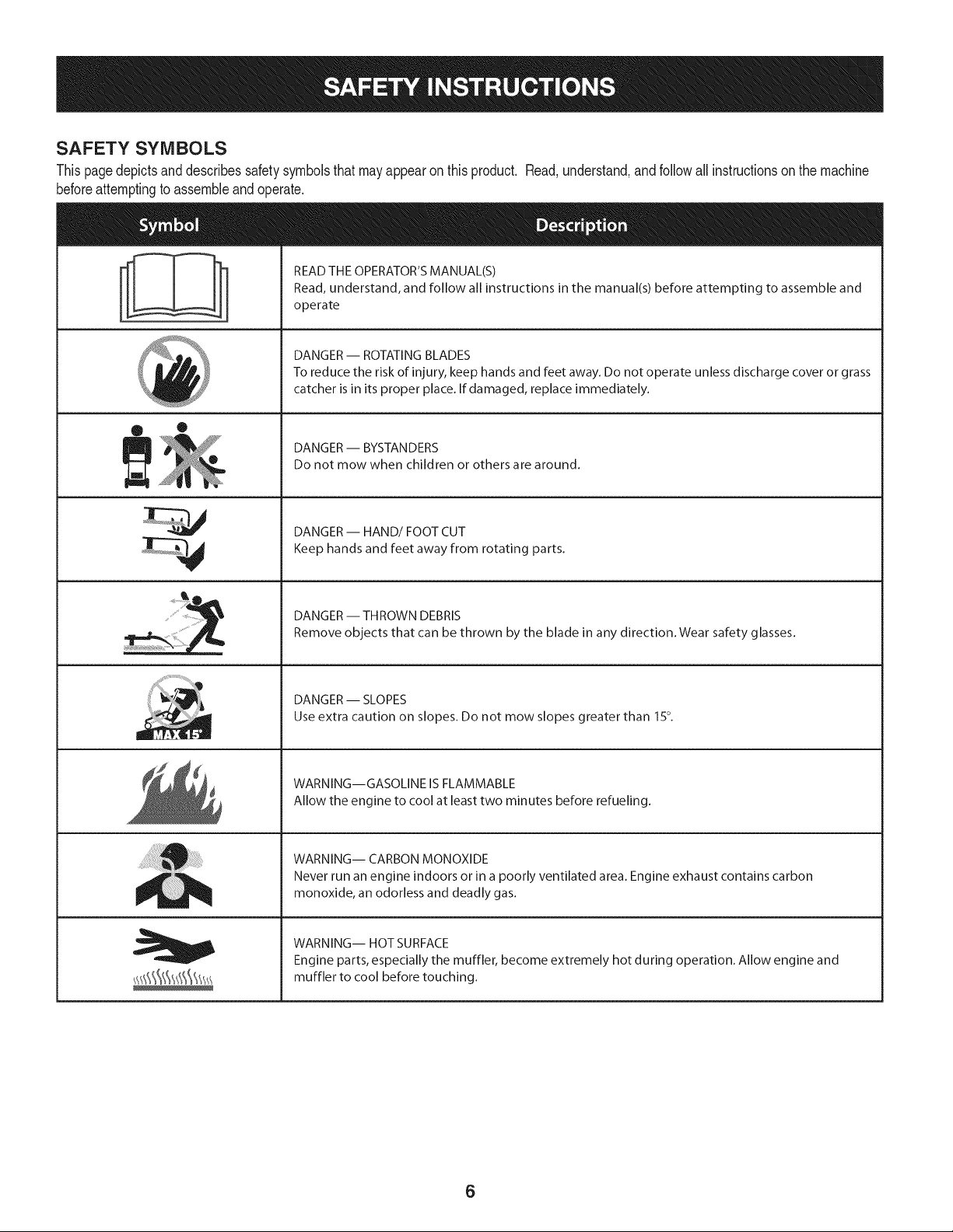
SAFETY SYMBOLS
Thispagedepictsanddescribessafetysymbolsthatmayappearonthisproduct. Read,understand,andfollowall instructionson the machine
beforeattemptingto assembleandoperate.
i
i
®
J
READ THE OPERATOR'S MANUAL(S)
Read, understand, and follow all instructions in the manual(s) before attempting to assemble and
operate
DANGER -- ROTATING BLADES
To reduce the risk of injury, keep hands and feet away. Do not operate unless discharge cover or grass
catcher is in its proper place. If damaged, replace immediately.
DANGER -- BYSTANDERS
Do not mow when children or others are around.
DANGER-- HAND/FOOT CUT
Keep hands and feet away from rotating parts.
DANGER -- THROWN DEBRIS
Remove objects that can be thrown by the blade in any direction. Wear safety glasses.
DANGER -- SLOPES
Use extra caution on slopes. Do not mow slopes greater than 150.
WARNING--GASOLINE IS FLAMMABLE
Allow the engine to cool at least two minutes before refueling.
WARNING-- CARBON MONOXIDE
Never run an engine indoors or in a poorly ventilated area. Engine exhaust contains carbon
monoxide, an odorless and deadly gas.
WARNING-- HOT SURFACE
Engine parts, especially the muffler, become extremely hot during operation. Allow engine and
muffler to cool before touching.
6
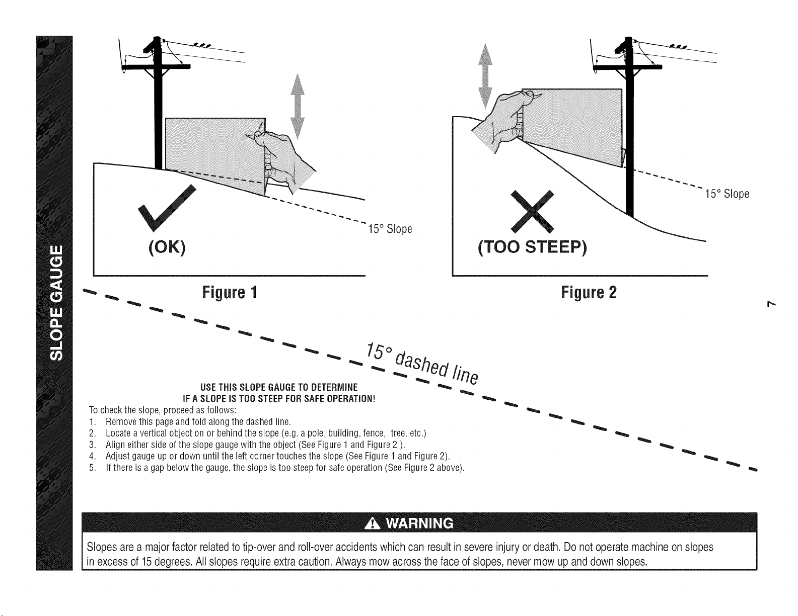
(OK)
15° Slope
X
(TOO STEEP)
15° Slope
_- _. Figure1
USETHiS SLOPEGAUGETO DETERMINE
iFA SLOPEiS TOOSTEEPFORSAFEOPERATION!
Tocheckthe slope,proceedas follows:
1. Removethis pageand fold alongthe dashedline.
2. Locateavertical objecton or behindthe slope(e.g.a pole, building,fence, tree, etc.)
3. Aligneither side of the slope gaugewith the object(SeeFigure1 andFigure2 ).
4. Adjust gaugeup or down until the left cornertouchesthe slope (SeeFigure1 and Figure2).
5.
_O._daShed._fine
If there is agap belowthe gauge,the slope is too steepfor safeoperation(SeeFigure2 above).
Figure2
Slopes are a majorfactor related to tip-over and roll-over accidents which can result in severe injury or death. Do not operate machine on slopes
in excess of 15degrees. All slopes requireextra caution.Always mow across the face of slopes, never mow up and down slopes.
IMPORTANT:Thisunitis shippedwithoil inthe engine.After
assembly,see page13for fuelandoil details.
IMPORTANT:Referenceto rightor leftside of the moweris observed
fromthe operatingposition.
Disconnectthe sparkplugwire andgroundit againstthe engineto
preventunintendedstarting.
LOOSE PARTS IN CARTON
Thefollowingitemsare packagedina bag:
Operator'sManual,Oildrainhose,Waterhosecoupler,EngineManual
TOOLS NEEDED FOR ASSEMBLY
A setof adjustablewrenchesandtiregauge
MOWER SET-UP
Shipping Brace Removal
Makesurethe lawnmower'sengineis off. Removetheignitionkey
beforeremovingthe shippingbrace.
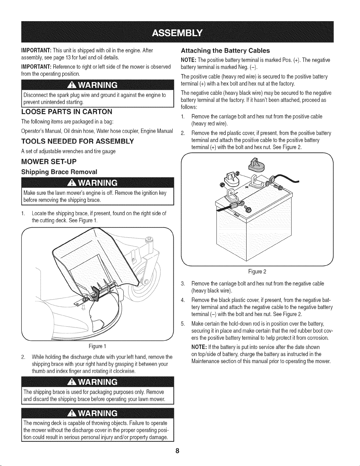
1. Locatethe shippingbrace,if present,foundon the rightside of
thecuttingdeck. SeeFigure1.
.
Figure1
Whileholdingthe dischargechutewithyour lefthand,removethe
shippingbracewithyourright handby graspingit betweenyour
thumbandindexfingerandrotatingit clockwise.
Attaching the Battery Cables
NOTE: Thepositivebatteryterminalis markedPos.(+).The negative
batteryterminalis markedNeg.(-).
The positivecable (heavyredwire)is securedto the positivebattery
terminal(+)witha hex boltandhex nutat thefactory.
The negativecable(heavyblackwire) maybe securedto the negative
batteryterminalat the factory.If it hasn'tbeenattached,proceedas
follows:
.
f
Removethe carriagebolt andhexnut fromthe positivecable
(heavyred wire).
Removethe redplasticcover,if present,fromthe positivebattery
terminalandattachthe positivecableto the positivebattery
terminal(+)withthe bolt andhexnut.See Figure2.
Figure2
3. Removethe carriagebolt andhexnut fromthe negativecable
(heavyblackwirel
4. Removethe blackplasticcover,if present,fromthe negativebat-
tery terminalandattachthe negativecableto the negativebattery
terminal(-) withthe boltand hexnut.SeeFigure2.
5. Makecertainthe hold-downrodis in positionoverthe battery,
securingit inplaceand makecertain that the red rubberbootcov-
ers the positivebatteryterminalto helpprotectit fromcorrosion.
NOTE: Ifthe batteryis putinto serviceafterthe dateshown
on top/sided battery,chargethe batteryas instructedin the
Maintenancesectionof thismanualprior to operatingthe mower.
Theshippingbraceis usedfor packagingpurposesonly.Remove
anddiscardthe shippingbracebeforeoperatingyourlawnmower.
Themowingdeckis capableof throwingobjects.Failureto operate
I the mowerwithoutthedischargecoverin the properoperatingposi-
ltion could resultin seriouspersonalinjuryand/or propertydamage.
8
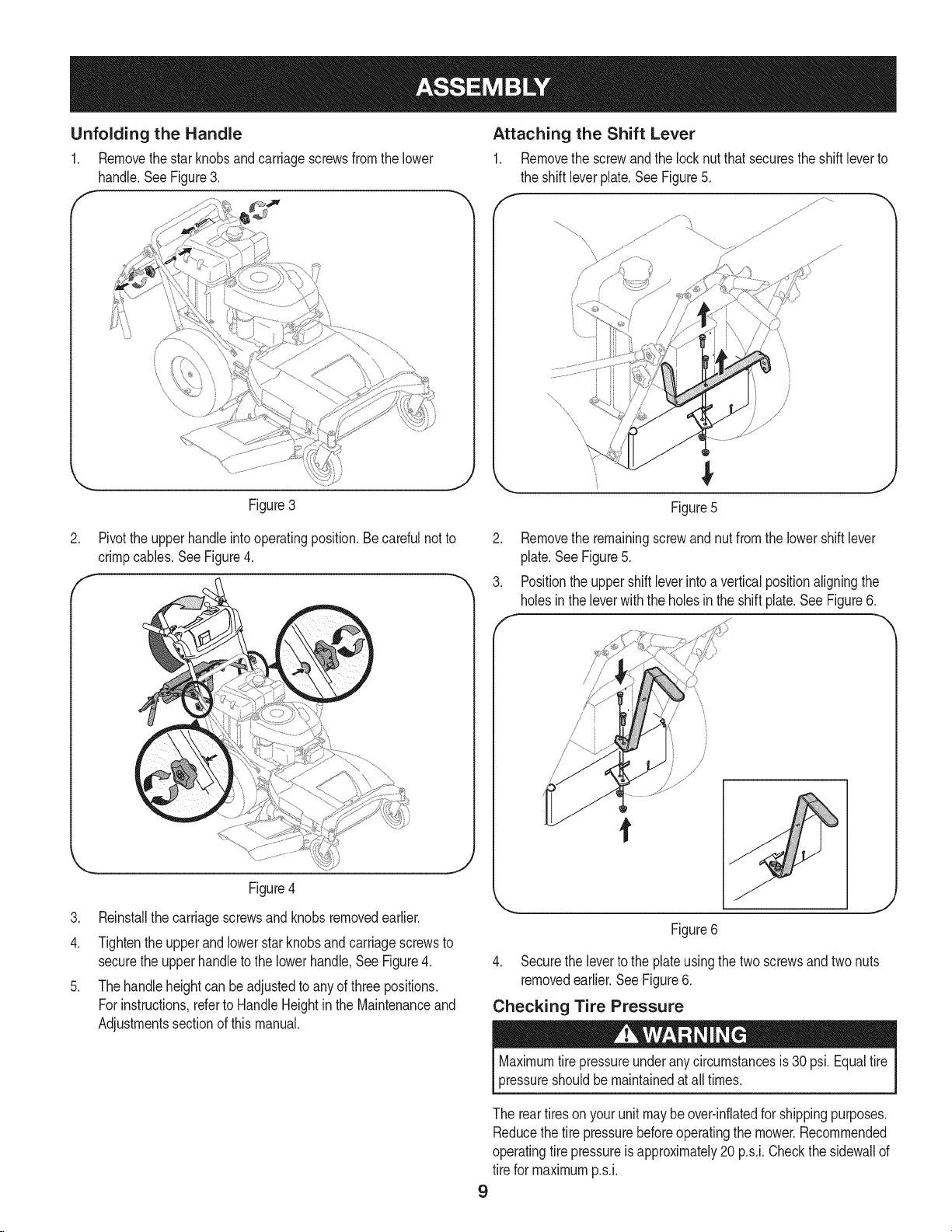
Unfolding the Handle
1. Removethestar knobsandcarriagescrewsfromthelower
handle.SeeFigure3.
.
Figure3
Pivotthe upperhandleintooperatingposition.Be careful notto
crimpcables.SeeFigure4.
Figure4
3. Reinstallthe carriagescrewsand knobs removedearlier.
4. Tightenthe upperand lowerstar knobsand carriagescrewsto
securethe upperhandleto the lowerhandle,See Figure4.
5. Thehandle heightcan be adjustedto anyof three positions.
For instructions,referto HandleHeightin the Maintenanceand
Adjustmentssectionof this manual.
Attaching the Shift Lever
1. Removethe screwandthe lock nutthat securesthe shift leverto
the shift leverplate.SeeFigure5.
f
Figure5
2. Removethe remainingscrewandnut fromthe lowershiftlever
plate.SeeFigure5.
3. Positionthe uppershift leverintoa verticalpositionaligningthe
holesinthe leverwith the holesinthe shift plate.SeeFigure6.
f
Figure6
4. Securethe leverto the plateusingthe two screwsandtwo nuts
removedearlier.SeeFigure6.
Checking Tire Pressure
Maximumtire pressureunderanycircumstancesis 30 psi.Equaltire
pressureshouldbe maintainedat all times.
The reartireson yourunit maybeover-inflatedfor shippingpurposes.
Reducethe tire pressurebeforeoperatingthe mower.Recommended
operatingtire pressureis approximately20p.s.i.Checkthe sidewallof
tire for maximump.s.i.
9
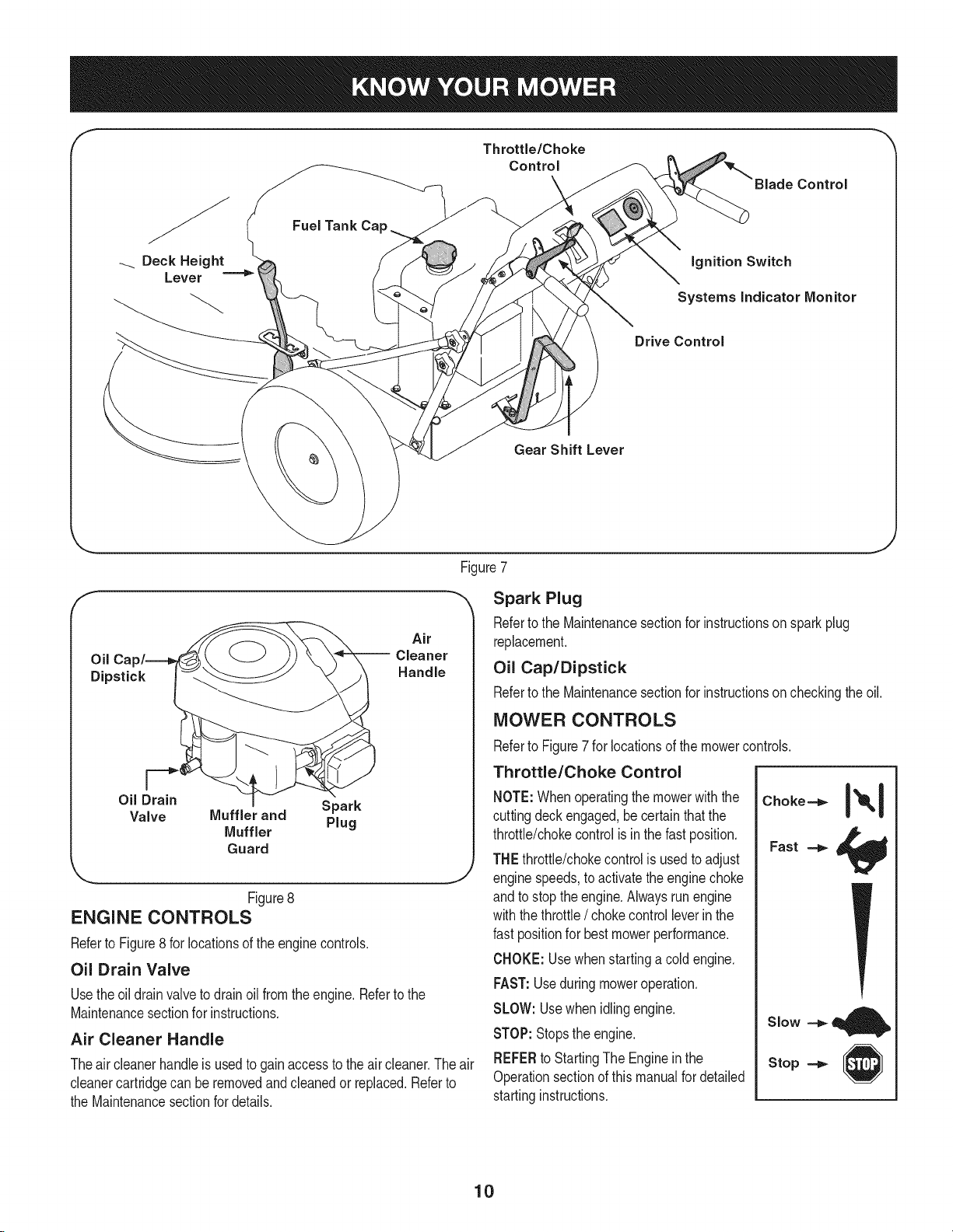
Deck Height
Lever ===='_
Fuel Tank Ca
ignition Switch
Systems indicator Monitor
Drive Control
Gear Shift Lever
Figure7
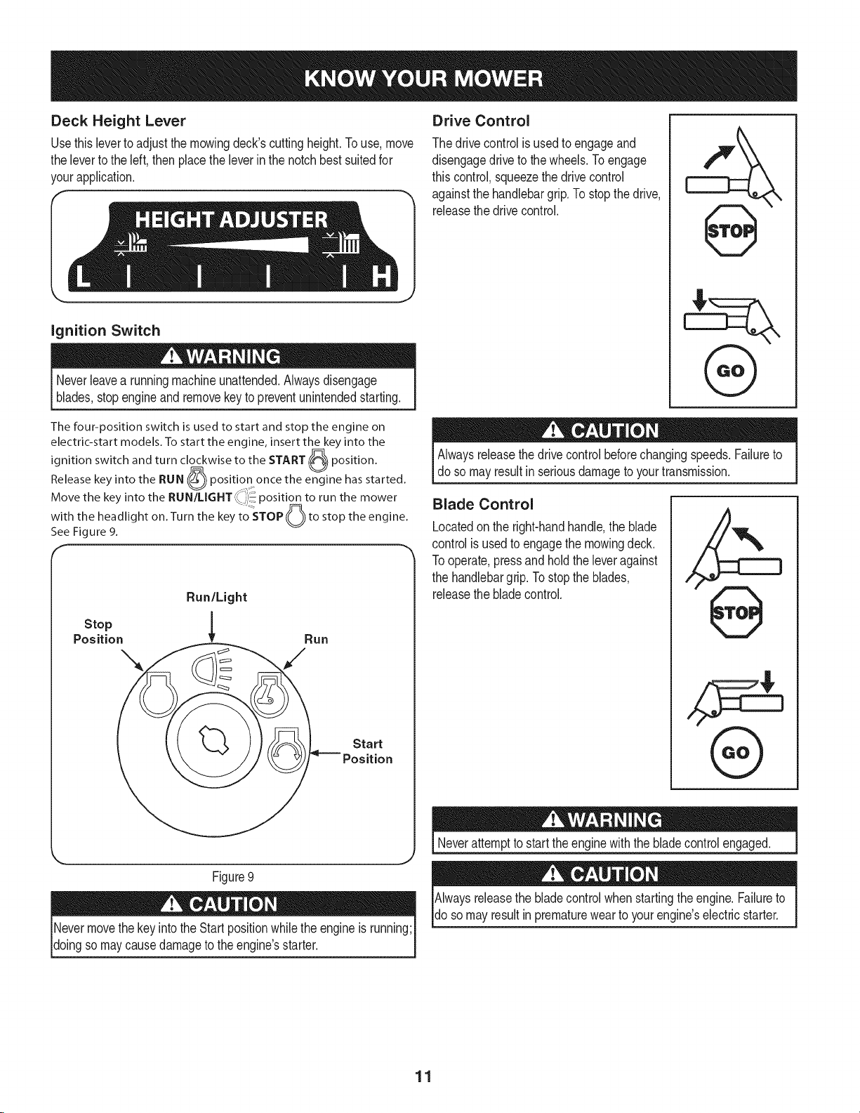
f
oil
Dipstick
Air
-- Cleaner
Handle
_,, J
Figure8
ENGINE CONTROLS
Referto Figure8for locationsof the enginecontrols.
Oil Drain Valve
Usetheoil drainvalveto drainoilfrom the engine.Referto the
Maintenancesectionfor instructions.
Air Cleaner Handle
Theair cleanerhandleis usedto gainaccessto the aircleaner.The air
cleanercartridgecan be removedandcleanedor replaced.Referto
the Maintenancesectionfor details.
Spark Plug
Referto the Maintenancesectionfor instructionsonspark plug
replacement.
Oil Cap/Dipstick
Referto the Maintenancesectionfor instructionsoncheckingthe oil.
MOWER CONTROLS
Referto Figure7 for locationsof the mowercontrols.
Throttle/Choke Control
NOTE:Whenoperatingthe mowerwiththe
cuttingdeckengaged,be certain that the
throttle/chokecontrolis inthe fast position.
THEthrottle/chokecontrolis usedto adjust
enginespeeds,to activatethe enginechoke
andto stopthe engine.Alwaysrun engine
withthe throttle/ chokecontrolleverinthe
fast positionfor bestmowerperformance.
CHOKE:Usewhenstartinga cold engine.
FAST:Useduringmoweroperation.
SLOW:Usewhenidling engine.
STOP:Stopsthe engine.
REFERto StartingThe Engineinthe
Operationsectionof thismanualfor detailed
startinginstructions.
Choke==_
Fast
Slow ==_
Stop
10
Deck Height Lever
Usethisleverto adjustthe mowingdeck'scuttingheight.To use,move
the leverto the left, then placetheleverin the notchbestsuitedfor
yourapplication.
ignition Switch
Neverleavea runningmachineunattended.Alwaysdisengage
blades,stopengineand removekey to preventunintendedstarting.
Drive Control
The drivecontrolis usedto engageand
disengagedriveto the wheels.Toengage
this control,squeezethe drivecontrol
againstthe handlebargrip.To stopthe drive,
releasethedrive control.
f
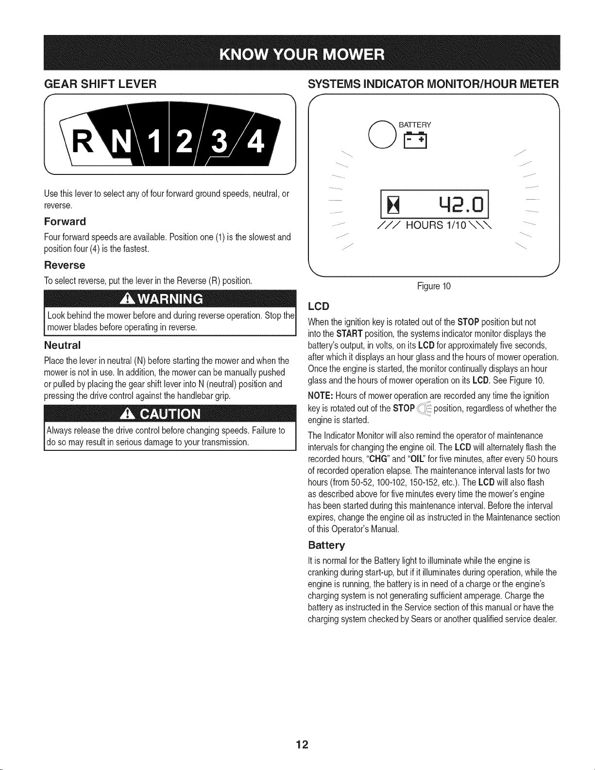
The four-position switch is used to start and stop the engine on
electric-start models, To start the engine, insert the key into the
r_
switch and turn clockwise to the START (PZ%_
ignition position,
Release key into the RUN ((_") position once the engine has started,
Move the key nto the RUN/LIGHT_ ,_-',)_pos t on to run the mower
to'STOP
F'_
with the headlight on, Turn the key (()) to stop the engine,
See Figure 9,
Run/Light
Stop 1
Position _ Run
Figure9
Nevermovethe keyintothe Startpositionwhile the engineis running;
doingso maycausedamageto the engine'sstarter.
Alwaysreleasethedrivecontrolbeforechangingspeeds.Failureto
do so mayresultin seriousdamageto yourtransmission.
Blade Control
Locatedonthe right-handhandle,the blade
controlis usedto engagethe mowingdeck.
Tooperate,pressand holdthe leveragainst
the handlebargrip.To stopthe blades,
releasethe bladecontrol.
,ik
Neverattemptto start theenginewiththe bladecontrolengaged.
Alwaysreleasethe bladecontrolwhenstartingthe engine.Failureto
do somayresultin prematurewearto yourengine'selectricstarter.
11
GEAR SHIFT LEVER
Usethisleverto selectanyof four forwardgroundspeeds,neutral,or
reverse.
Forward
Fourforwardspeedsareavailable.Positionone (1) is the slowestand
positionfour(4) is thefastest.
Reverse
Toselectreverse,putthe leverin the Reverse(R) position.
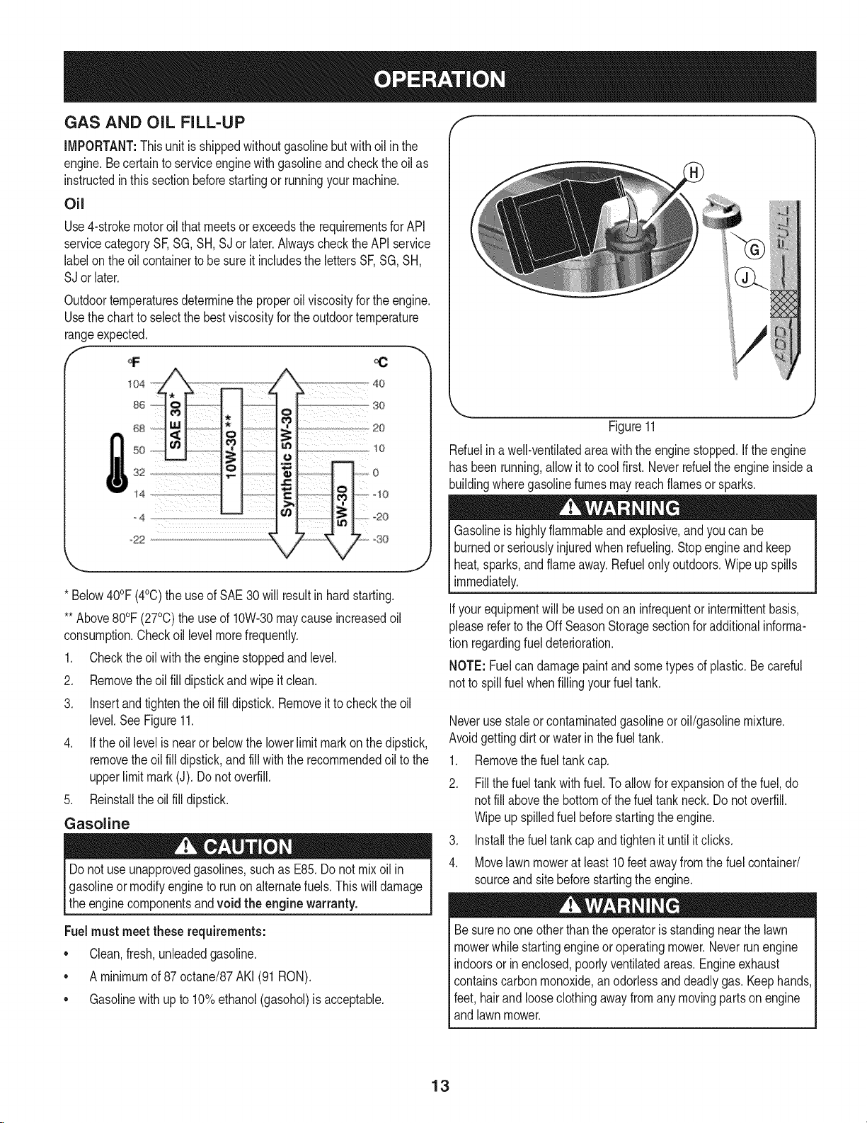
SYSTEMS INDICATOR MONITOR/HOUR METER
jf
BATTERY
42.0
/// HOURS 1/10 \\\
jJ
j j/
Figure10
Lookbehindthe mowerbeforeandduring reverseoperation.Stopthe
mowerbladesbeforeoperatingin reverse.
Neutral
Placethe leverinneutral(N) beforestartingthe mowerandwhenthe
moweris not inuse.In addition,the mowercan be manuallypushed
orpulledby placingthe gear shiftleverinto N (neutral)positionand
pressingthe drivecontrolagainstthe handlebargrip.
Alwaysreleasethe drivecontrolbeforechangingspeeds.Failureto
doso mayresultin seriousdamageto yourtransmission.
LCD
Whenthe ignitionkeyis rotatedout of the STOPpositionbut not
intothe STARTposition,the systemsindicatormonitordisplaysthe
battery'soutput,involts,onits LCDfor approximatelyfiveseconds,
afterwhich it displaysan hourglassand the hoursof moweroperation.
Oncethe engineis started,the monitorcontinuallydisplaysan hour
glassand the hoursof moweroperationon its LCD.SeeFigure10.
NOTE:Hoursof moweroperationarerecordedanytimethe ignition
keyis rotatedout of the STOP_i _position,regardlessof whetherthe
engineis started.
The IndicatorMonitorwill also remindthe operatorof maintenance
intervalsfor changingthe engineoil. The LCDwill alternatelyflashthe
recordedhours,"CHG"and"OIL' forfive minutes,after every50 hours
of recordedoperationelapse.The maintenanceintervallastsfor two
hours(from50-52, 100-102,150-152,etc.).The LeD willalso flash
as describedabovefor fiveminuteseverytimethe mower'sengine
hasbeenstartedduring this maintenanceinterval.Beforethe interval
expires,changetheengineoil as instructedin the Maintenancesection
of this Operator'sManual.
Battery
Itis normalfor the Batterylightto illuminatewhilethe engineis
crankingduringstart-up,but if it illuminatesduringoperation,whilethe
engineis running,the batteryis in needof a chargeor the engine's
chargingsystemis not generatingsufficientamperage.Chargethe
batteryas instructedin the Servicesectionof thismanualor havethe
chargingsystemcheckedby Searsor anotherqualifiedservicedealer.
12
GAS AND OiL FILL-UP
IMPORTANT:Thisunitis shippedwithoutgasolinebutwithoil inthe
engine.Becertainto serviceenginewithgasolineand checkthe oil as
instructedin thissectionbeforestartingor runningyour machine.
Oil
Use4-strokemotoroil thatmeetsor exceedsthe requirementsfor API
servicecategorySF,SG,SH,SJ or later.Alwayscheckthe APIservice
labelon the oil containerto be sure it includesthe lettersSF,SG,SH,
SJ orlater.
* Below40°F(4°C)the use of SAE30will resultinhardstarting.
** Above80°F(27°C)theuse of 10W-30maycauseincreasedoil
consumption.Checkoil levelmorefrequently.
1. Checktheoil withthe enginestoppedandlevel.
2. Removetheoil fill dipstickand wipe it clean.
3. Insertand tightenthe oil fill dipstick.Removeit to checkthe oil
level.See Figure11.
4. If theoil levelis near or belowthe lowerlimit markon the dipstick,
removethe oil fill dipstick,andfill withthe recommendedoil to the
upperlimitmark (J). Donot overfill.
5. Reinstallthe oil fill dipstick.
Gasoline
Do notuse unapprovedgasolines,suchas E85.Do not mixoilin
gasolineormodifyengineto runon alternatefuels.This will damage
the enginecomponentsandvoid the engine warranty.
Fuelmustmeetthese requirements:
• Clean,fresh,unleadedgasoline.
• A minimumof 87 octane/87AKI (91RON).
• Gasolinewithup to 10%ethanol(gasohol)is acceptable.
Figure11
Refuelina well-ventilatedareawiththe enginestopped.Ifthe engine
hasbeenrunning,allowit to cool first.Neverrefuelthe engineinsidea
buildingwheregasolinefumesmayreachflamesor sparks.
Gasolineis highlyflammableandexplosive,andyou can be
burnedor seriouslyinjuredwhenrdueling. Stopengineand keep
heat,sparks,and flameaway.Refuelonlyoutdoors.Wipe up spills
immediately.
if your equipmentwill be usedonan infrequentorintermittentbasis,
pleasereferto the Off SeasonStoragesectionforadditionalinforma-
tion regardingfuel deterioration.
NOTE:Fuelcan damagepaintandsometypes of plastic.Becareful
notto spillfuel whenfillingyour fueltank.
Neverusestaleor contaminatedgasolineor oil/gasolinemixture.
Avoidgettingdirt or waterin the fueltank.
1. Removethe fueltank cap.
2. Fillthe fuel tankwith fuel.To allowforexpansionof the fuel, do
notfill abovethe bottomof the fuel tankneck.Do notoverfill.
Wipeupspilledfuel beforestartingtheengine.
3. Installthe fuel tank capand tighten it until it clicks.
4. Movelawnmowerat least 10 feetaway fromthe fuel container/
sourceandsite beforestartingthe engine.
Besurenoone otherthan the operatoris standingnear the lawn
mowerwhilestartingengineoroperatingmower.Neverrunengine
indoorsor inenclosed,poorlyventilatedareas.Engineexhaust
containscarbonmonoxide,anodorlessand deadlygas. Keephands,
feet, hairand looseclothingawayfrom any movingpartson engine
andlawnmower.
13
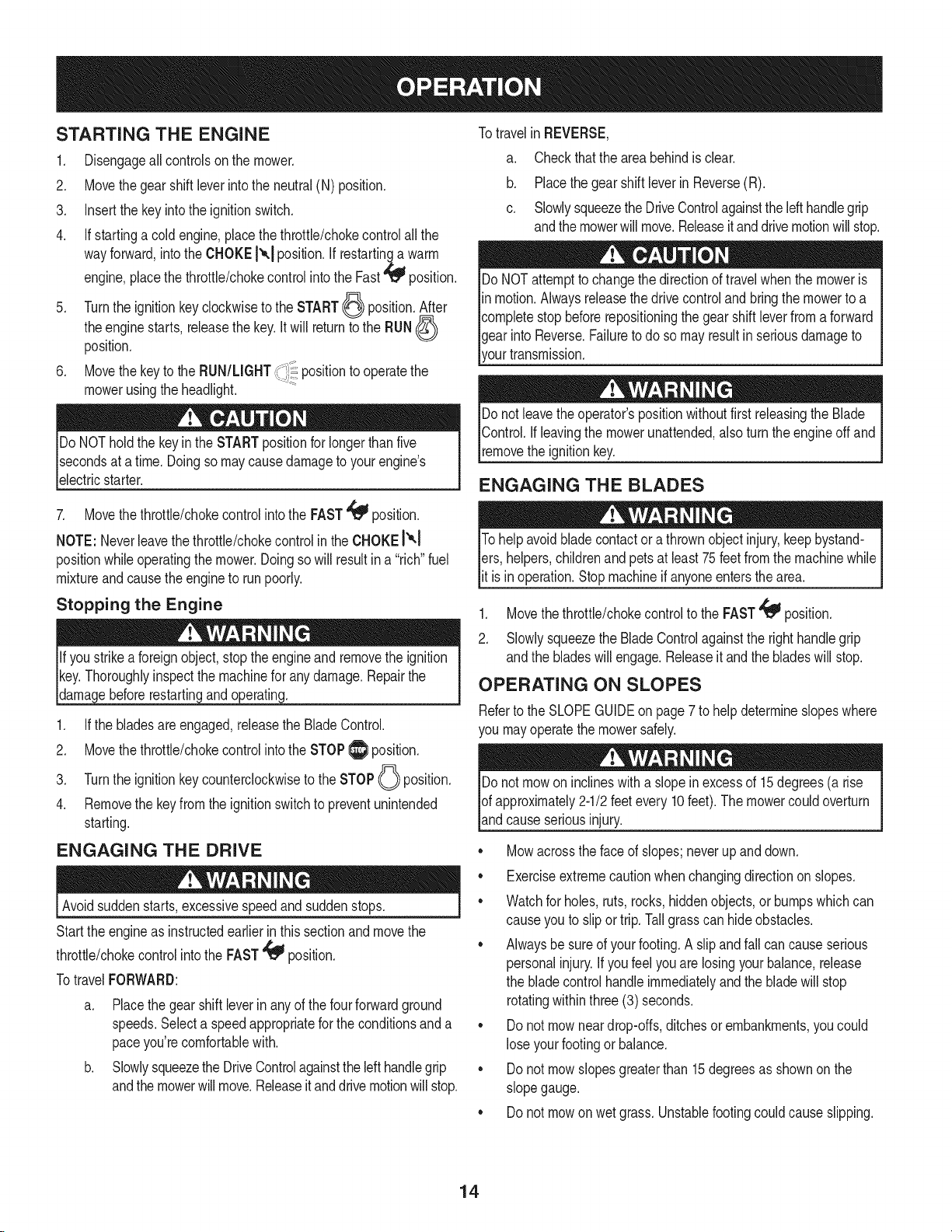
STARTING THE ENGINE
.
2.
3.
4.
.
.
Disengageallcontrolson the mower.
Movethe gearshiftleverinto the neutral(N) position.
Insertthe keyintothe ignitionswitch.
If startinga cold engine,placethe throttle/chokecontrolallthe
wayforward,intothe CHOKE1_.1position.If restartinga warm
engine,placethe throttle/chokecontrolintothe Fast_ position.
Turnthe ignitionkeyclockwiseto the START_ position.After
theenginestarts,releasethe key.it will returnto the RUN(_
position.
MovethekeytotheRUN/LGNT positiontooperatethe
mowerusingthe headlight.
Do NOTholdthe keyinthe STARTpositionfor longerthan five
secondsat a time.Doingso maycausedamageto yourengine's
electricstarter.
7. Movethe throttle/chokecontrolintothe FAST'_ position.
NOTE: Neverleavethe throttle/chokecontrolinthe CHOKEI'_!
positionwhileoperatingthemower.Doingso will resultin a "rich"fuel
mixtureandcausetheengineto run poorly.
Stopping the Engine
e beforerestartingandoperating.
1. If the bladesare engaged,releasethe BladeControl.
2. Movethe throttle/chokecontrolintothe STOPlI_ position.
3. Turnthe ignitionkey counterclockwiseto the STOPO position.
4. Removethe keyfrom the ignitionswitchto preventunintended
starting.
ENGAGING THE DRIVE
Avoidsuddenstarts,excessivespeedandsuddenstops.
Startthe engineas instructedearlierin this sectionand movethe
throttle/chokecontrolintothe FAST'_ position.
TotravelFORWARD:
a. Placethegear shift leverin anyof the fourforwardground
speeds.Selecta speedappropriatefor the conditionsanda
paceyou'recomfortablewith.
b. Slowlysqueezethe DriveControlagainstthe left handlegrip
andthe mowerwillmove.Releaseit anddrivemotionwillstop.
Totravelin REVERSE,
a. Checkthat the area behindis clear.
b. Placethe gearshift leverinReverse(R).
c. Slowlysqueezethe DriveControlagainstthelefthandlegrip
andthemowerwill move.Releaseitanddrivemotionwillstop.
DoNOTattemptto changethe directionof travelwhenthe moweris
in motion.Alwaysreleasethedrivecontrolandbringthe mowerto a
completestopbeforerepositioningthegearshift leverfromaforward
gearinto Reverse.Failuretodo so mayresultin seriousdamageto
rourtransmission.
Donot leavethe operator'spositionwithoutfirst releasingthe Blade
Control.Ifleavingthe mowerunattended,also turnthe engineoffand
removethe ignitionkey.
ENGAGING THE BLADES
Tohelpavoidbladecontactor a thrownobject injury,keepbystand-
lets, helpers,childrenandpets at least75 feet from the machinewhile
lit is inoperation.Stopmachineif anyoneentersthe area.
1. Movethethrottle/chokecontrolto the FAST_ position.
2. Slowly squeezethe BladeControlagainstthe righthandlegrip
andthe bladeswill engage.Releaseit andthe bladeswill stop.
OPERATING ON SLOPES
Referto the SLOPEGUIDEon page7 to helpdetermineslopeswhere
you mayoperatethemowersafely.
Donot mowon inclineswitha slopeinexcessof 15degrees(a rise
of approximately2-1/2feetevery 10feet).The mowercouldoverturn
andcause seriousinjury.
• Mowacrossthefaceof slopes;neverupanddown.
• Exerciseextremecautionwhenchangingdirectionon slopes.
• Watchfor holes,ruts, rocks,hiddenobjects,or bumpswhich can
causeyou to slip ortrip.Tallgrasscan hideobstacles.
• Alwaysbesureof yourfooting.A slipandfall can causeserious
personalinjury.Ifyou feelyou arelosingyourbalance,release
the bladecontrolhandleimmediatelyand the blade willstop
rotatingwithinthree (3) seconds.
• Donot mowneardrop-offs,ditchesor embankments,you could
lose yourfootingor balance.
• Donot mowslopesgreaterthan 15degreesas shownon the
slopegauge.
• Donot mowon wetgrass.Unstablefootingcouldcauseslipping.
14
USING THE DECK HEIGHT LEVER
Toraiseor lowerthecuttingdeck, movethe deck heightleverto the
left,then placeit inthe notchbest suitedforyour application.
MOWING
Thefollowinginformationwill behelpfulwhenoperatingyour mower.
Planyour mowingpatternto avoiddischargeof materialstoward
roads,sidewalks,bystanders.Also,avoiddischargingmaterial
againstawall orobstructionwhich maycause dischargedmaterialto
ricochetbacktowardtheoperator.
• Do not mowat fastgroundspeeds,especiallyif a mulchkitor
grasscollectoris installed.
• Do notcut thegrasstoo short.Shortgrassis proneto weed
growthandyellowsquicklyin dry weather.
• Alwaysoperatethe mowerwiththethrottle/chokecontrolin the
FAST_ positionwhile mowing.
• For bestresultsit is recommendedthatthe firsttwolaps becut
withthe dischargethrowntowardsthe center.Afterthe first two
laps,reversethe directionto throwthe dischargeto the outside
for the balanceof cutting.Thiswill givea betterappearanceto the
lawn.
Do NOTattemptto mowheavybrushandweedsor extremelytall
grass.Yourmoweris designedto mowlawns,NOTclear brush.
Keepthe bladessharpandreplacethe bladeswhenworn.
Afterstrikinga foreignobject,stopthe engine,disconnectthe spark
plugwireandgroundagainstthe engine.Thoroughlyinspectthe
mowerfor any damage.AlwaysInspectthe bladetimingbelt as
instructedin the Maintenancesectionof thismanual.Repairthe
damagebeforestartingandoperatingthe mower.
MULCHING
TheCraftsmanProWideCutmoweris equippedwitha mulchkit (sup-
pliedwith the mower),whichusesspecialbladesto recirculategrass
clippingsrepeatedlybeneaththe cuttingdeck.The ultra-fineclippings
arethenforced backinto the lawnwherethey act asa naturalfertilizer.
Observethe followingpointsfor the bestresultswhenmulching.
• Neverattemptto mulchif the lawnis damp.Wetgrasstends
to stickto the undersideof thecuttingdeckpreventingproper
mulchingof the clippings.
Do NOTattemptto mulchmorethan1/3the totalheightof the
grass.Doingsowill causetheclippingsto clumpupbeneaththe
deckand not be mulchedeffectively.
• Maintaina slowgroundspeedto allowthe grassclippingsmore
timeto effectivelybe mulched.
• Alwayskeepthe throttlecontrolleverinthe FAST,_ position
whilemowing.Failingto keepthe engineat full throttleplaces
strainon the mower'sengineanddoes notallowthe bladesto
properlymulchthe grassclippings.
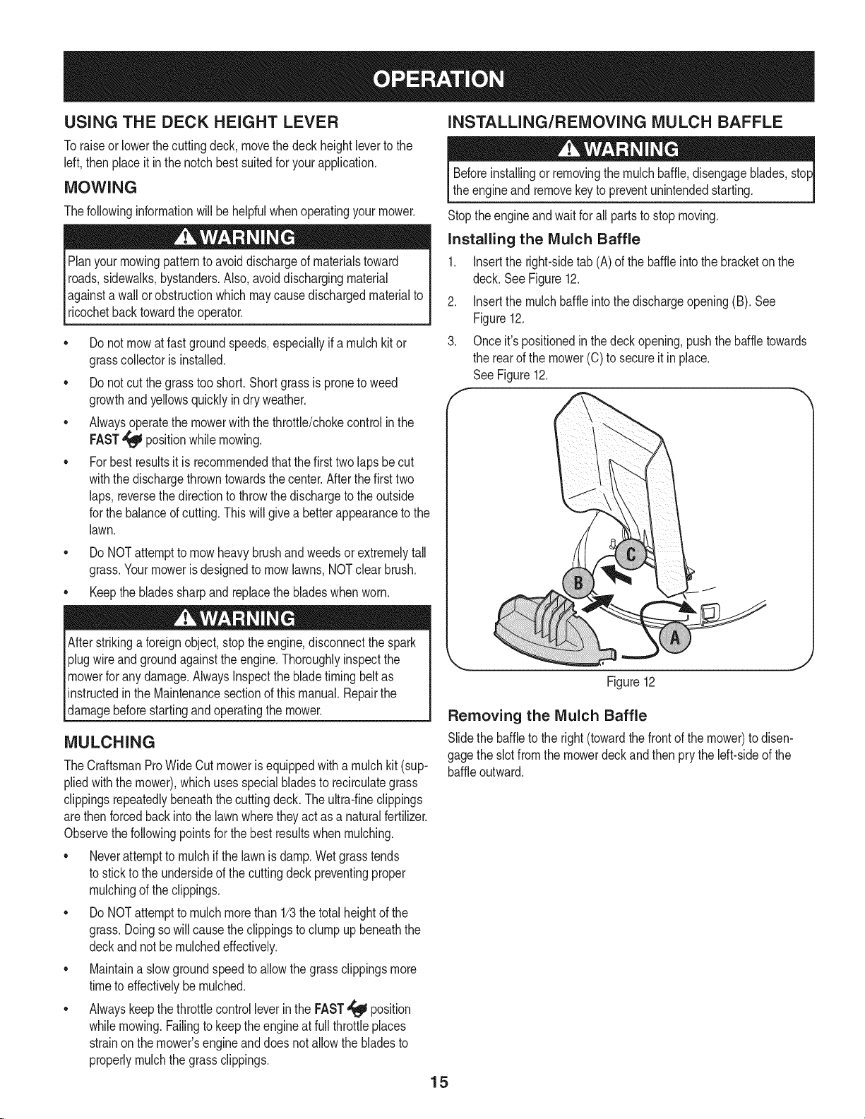
INSTALLING/REMOVING MULCH BAFFLE
Beforeinstallingor removingthe mulchbaffle,disengageblades,sto
the engineand removekeyto preventunintendedstarting.
Stoptheengineandwait for all parts to stop moving.
Installing the Mulch Baffle
1. Insertthe right-sidetab (A) of the baffleinto the bracketon the
deck. SeeFigure12.
2. Insertthe mulchbaffleinto thedischargeopening(B). See
Figure12.
3. Onceit's positionedin thedeckopening,pushthe baffletowards
the rearof the mower(C) to secureit inplace.
SeeFigure12.
Figure12
Removing the Mulch Baffle
Slidethe baffleto the right(towardthe frontof the mower)to disen-
gagethe slot fromthe mowerdeck and then prythe left-sideof the
baffleoutward.
15
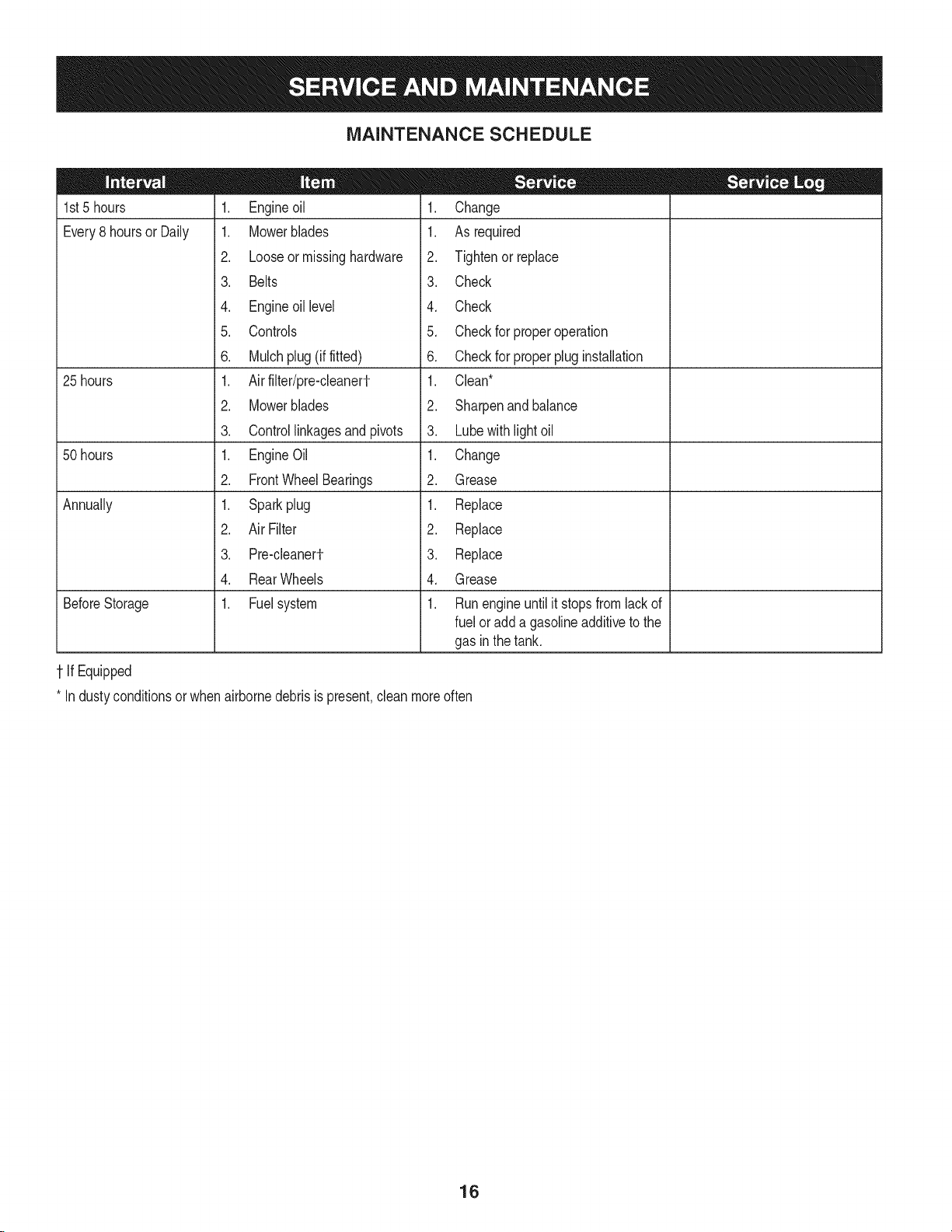
MAINTENANCE SCHEDULE
1st5 hours
Every8 hoursor Daily
25 hours
50 hours
Annually
BeforeStorage
1. Engineoil
1. Mowerblades
2. Looseor missinghardware
3. Belts
4. Engineoil level
5. Controls
6. Mulchplug (if fitted)
1. Air filter/pre-cleanerf
2. Mowerblades
3. Controllinkagesand pivots
1. EngineOil
2. FrontWheelBearings
1. Sparkplug
2. Air Filter
3. Pre-cleanerf
4. RearWheels
1. Fuelsystem
1-IfEquipped
1. Change
1. As required
2. Tightenor replace
3. Check
4. Check
5. Checkfor properoperation
6. Checkfor properplug installation
1. Clean*
2. Sharpenand balance
3. Lubewithlightoil
1. Change
2. Grease
1. Replace
2. Replace
3. Replace
4. Grease
1. Runengineuntilit stopsfrom lackof
fuel oradda gasolineadditiveto the
gas in thetank.
* Industyconditionsor whenairbornedebrisis present,cleanmoreoften
16
MAINTENANCE
Beforeperformingany maintenanceor repairs,disengageblades,
stopengineand removekey to preventunintendedstarting.
GENERAL RECOMMENDATIONS
Alwaysobservesafetyruleswhenperforminganytype of
maintenanceon the mower.
Thewarrantyon thislawnmowerdoesnot coveritemsthathave
beensubjectedto operatorabuseor negligence.To receivefull
valuefromwarranty,operatormustmaintainthe lawnmoweras
instructedinthismanual.
• Changingof engine-governedspeedwill voidenginewarranty.
• Alladjustmentsshouldbecheckedat leastonceeach season.
• Periodicallycheckall fastenersandmakesuretheyare tight.
ENGINE MAINTENANCE
Checking the Engine Oil
Checkoillevelbeforeeachuse.Stopengineandwait severalminutes
beforecheckingoil level.Withengineon levelground,
the oilmust beto FULLmarkondipstick.
1. RemovetheOil Cap/Dipstickandwipe witha
cleancloth.
2. Replaceandtighten Oil Cap/Dipstick.Remove
OilCap/Dipstickandcheckoil level.Level
shouldbeat FULLmark.
3. If needed,add oil slowlyinto theengine oil fill. Recheckoil level.
Do notoverfill.
4. ReinsertOil Cap/Dipstickand tighten.
Do notoverfill.Overfillingwithoilmaymakethe enginehardto start,
or not to start.If overthe FULLmarkonthe dipstick,drainoil levelto
FULLmarkondipstick.
Changing the Engine Oil
Ifthe enginehas beenrecentlyrun,the engine,mufflerand sur-
roundingmetalsurfaceswill be hotandcan causeburnsto the skin.
Exercisecautionto avoidburns.
Theoil inthe engineshouldbe changedafterthe first five hoursof
operationandevery50 hoursof operation.
1. Runthe enginefor a fewminutesto allowtheoil in the crankcase
to warmup. Warmoilwill flowmorefreelyand carryawaymoreof
the enginesedimentwhichmay havesettledat the bottomof the
crankcase.Usecareto avoidburnsfromhotoil.
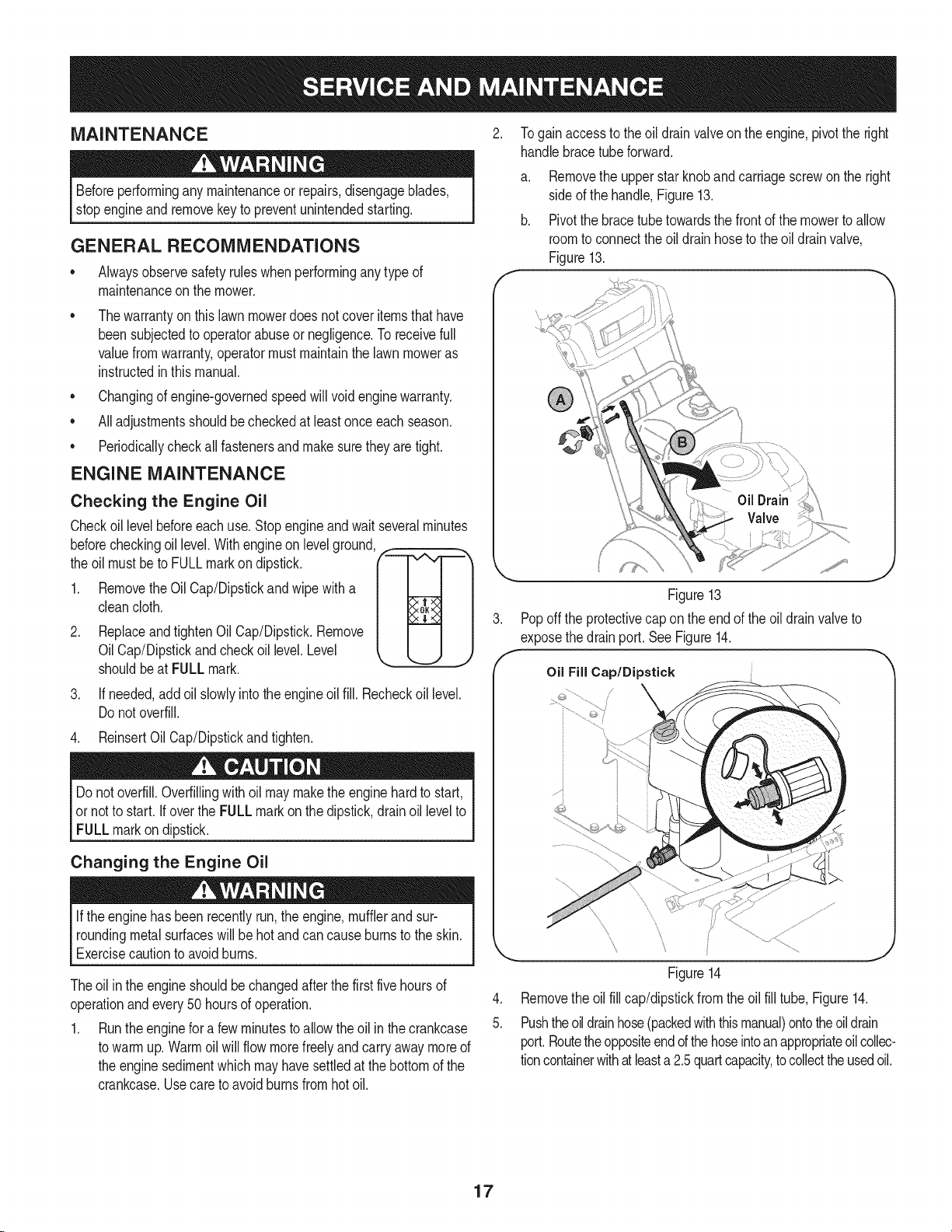
.
5.
Togainaccessto theoil drain valveon the engine,pivotthe right
handlebracetube forward.
a. Removethe upperstarknobandcarriagescrewonthe right
sideof the handle,Figure13.
b. Pivotthe bracetube towardsthe frontof the mowerto allow
roomto connectthe oildrain hoseto the oildrainvalve,
Figure13.
Figure13
Popoff the protectivecap on theendof the oil drainvalveto
exposethe drainport. See Figure14.
Oil Fiil Cap/Dipstick
_\ j,J"
....."",,, iij ...............................................
Figure14
Removethe oilfill cap/dipstickfromtheoil fill tube,Figure14.
Pushtheoildrainhose(packedwiththismanual)ontotheoildrain
port.Routetheoppositeendd thehoseintoanappropriateoilcollec-
tioncontainerwithat leasta 2.5quartcapacity,to collectthe usedoil.
17
6, Releasethe valve bypressingthe two tabs inwardwhilepulling
thevalveout,Theoil will beginto drainout of the engine,
7. Afterthe oil has finisheddraining,pressthe two tabs inwardand
pushthe oildrainvalveback in to lock the valveclosed,Remove
the hose,andre-capthe end of the oil drain valveto keepdebris
fromenteringthedrainport.
8. Refillthe enginewith new motoroil untilthe oil levelon the
dipstickreadsFULL.Replacethe oilfill cap/dipstick.
9. Pivotthe right handlebracetube back intoposition.Align the
middleholeinthe bracetubewiththe holein the handle.Secure
withthe starknobandcarriagescrewremovedearlier.
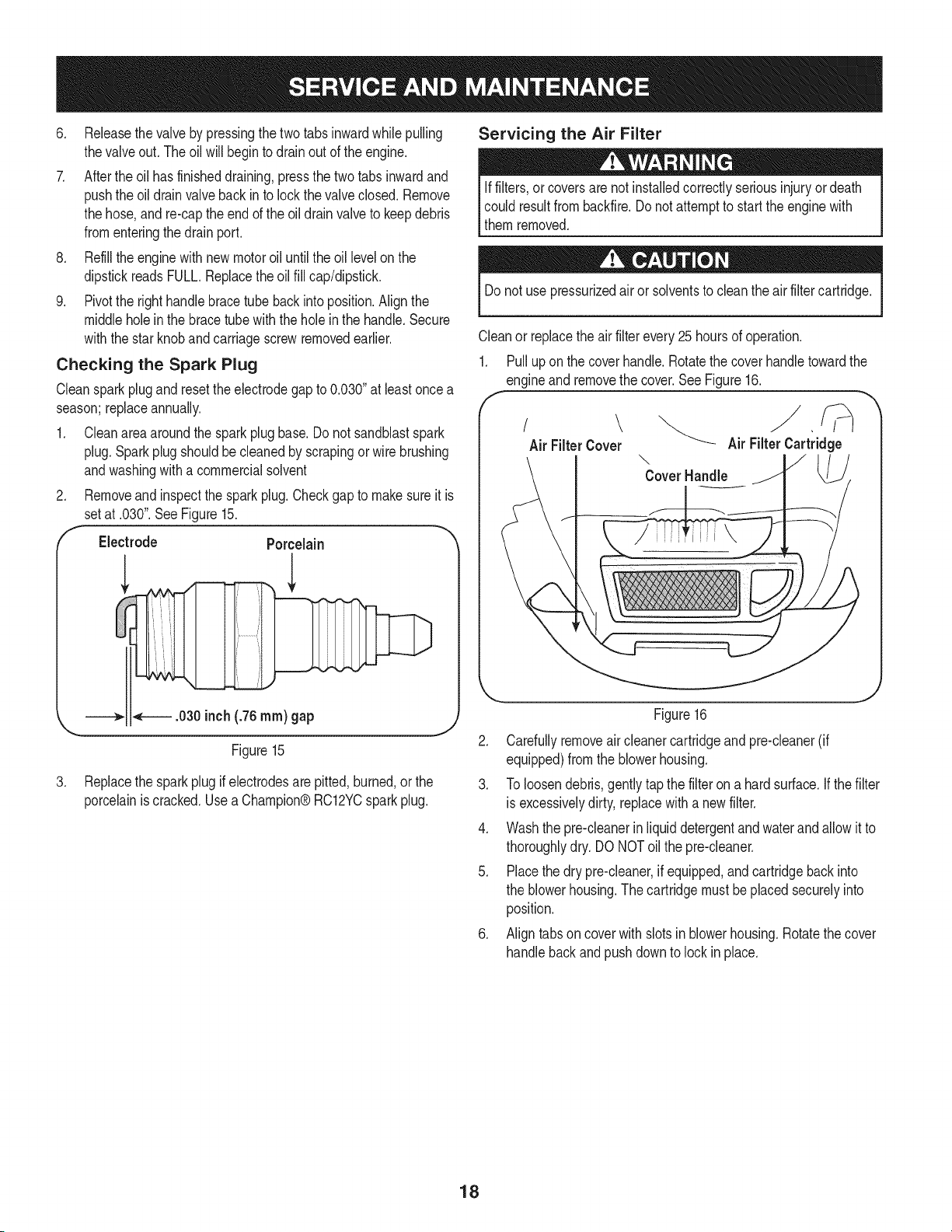
Checking the Spark Plug
Cleansparkplugand reset theelectrodegap to 0.030"at leastoncea
season;replaceannually.
1. Cleanareaaroundthe spark plug base.Do not sandblastspark
plug.Sparkplugshouldbecleanedby scrapingor wire brushing
andwashingwith a commercialsolvent
Removeand inspectthe sparkplug.Checkgapto makesureit is
setat .030".SeeFigure15.
.
f
Electrode Porcelain
.030inch(26 ram) gap
.
Figure15
Replacethe sparkplugif electrodesarepitted,burned,or the
porcelainis cracked.Usea Champion®RC12YCsparkplug.
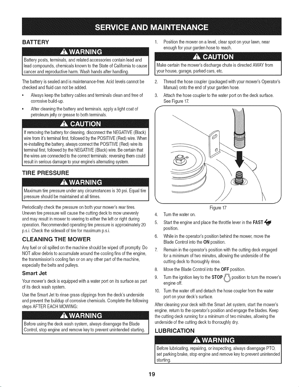
Servicing the Air Filter
Iffilters,or coversare notinstalledcorrectlyseriousinjuryordeath
could resultfrombackfire.Do notattemptto startthe enginewith
themremoved.
Donot use pressurizedairor solventsto cleantheair filtercartridge.
Cleanor replacethe airfilterevery25hoursof operation.
1. Pull up on the coverhandle.Rotatethe coverhandletowardthe
engineand removethe cover.See Figure16.
f -,,
\
Air FilterCover Air FilterCartridge
\
CoverHandle _
Figure16
2. Carefullyremoveair cleanercartridgeand pre-cleaner(if
equipped)fromthe blowerhousing.
3. To loosendebris,gently tapthe filter on a hardsurface.If thefilter
is excessivelydirty,replacewitha newfilter.
4. Washthe pre-cleanerin liquid detergentand waterandallow it to
thoroughlydry. DONOToil the pre-cleaner.
5. Placethe dry pre-cleaner,if equipped,andcartridgebackinto
the blowerhousing.Thecartridgemustbeplacedsecurelyinto
position.
6. Align tabs on cover with slotsin blowerhousing.Rotatethe cover
handlebackand pushdownto lock in place.
18
BATTERY
Batteryposts,terminals,andrelatedaccessoriescontainlead and
leadcompounds,chemicalsknownto the Stateof Californiato cause
cancerand reproductiveharm.Washhandsafter handling.
1. Positionthe moweron a level,clear spoton yourlawn,near
enoughfor yourgardenhoseto reach.
Makecertainthe mower'sdischargechuteis directedAWAYfrom
yourhouse,garage,parkedcars,etc.
Thebatteryis sealedandis maintenance-free.Acid levelscannotbe
checkedandfluidcan not beadded.
• Alwayskeepthe batterycablesandterminalscleanand freeof
corrosivebuild-up.
Aftercleaningthe batteryand terminals,apply a light coat of
petroleumjelly or greaseto bothterminals.
If removingthe batteryforcleaning,disconnectthe NEGATIVE(Black)
wire fromit's terminalfirst,followedby thePOSITIVE(Red)wire.When
re-installingthe battery,alwaysconnectthe POSITIVE(Red)wireits
terminalfirst,followedby theNEGATIVE(Black)wire.Becertainthat
the wiresareconnectedto thecorrectterminals;reversingthemcould
resultinseriousdamageto yourengine'salternatingsystem.
TIRE PRESSURE
Maximumtire pressureunderany circumstancesis 30 psi.Equaltire
pressureshouldbemaintainedat all times.
Periodicallycheckthe pressureonbothyour mower'sreartires.
Uneventire pressurewill causethe cuttingdeckto mowunevenly
andmay resultin mowertoveeringto eitherthe leftor rightduring
operation.Recommendedoperatingtire pressureis approximately20
p.s.i.Checkthe sidewallof tire for maximump.s.i.
CLEANING THE MOWER
Anyfuel oroil spilledonthe machineshouldbe wipedoffpromptly.Do
NOTallowdebristo accumulatearoundthecoolingfinsof the engine,
the transmission'scoolingfanor onany otherpartof themachine,
especiallythebeltsandpulleys.
Smart Jet
Yourmower'sdeckis equippedwitha waterport onits surfaceas part
of its deckwashsystem.
Usethe SmartJetto rinsegrassclippingsfromthe deck'sunderside
andpreventthe buildupof corrosivechemicals.Completethe following
stepsAFTEREACHMOWING:
Beforeusingthe deckwashsystem,alwaysdisengagethe Blade
Control,stopengineand removekeyto preventunintendedstarting.
2. Threadthe hosecoupler(packagedwith your mower'sOperator's
Manual)onto the endof yourgardenhose.
3. Attachthe hosecouplerto thewater porton thedeck surface.
SeeFigure17.
f
Figure17
4. Turnthewater on.
5. Startthe engineandplacethe throttleleverin the FAST,_
position.
6. Whilein the operator'spositionbehindthe mower,movethe
BladeControlintothe ON position.
7. Remainin theoperator'spositionwiththe cuttingdeck engaged
for a minimumof twominutes,allowingthe undersideof the
cuttingdeckto thoroughlyrinse.
8. Movethe BladeControlintothe OFFposition.
9. Turnthe ignitionkeyto the STOP(_ positionto turnthe mower's
engineoff.
10. Turnthewater off and detach thehose couplerfrom the water
portonyour deck'ssurface.
Aftercleaningyourdeck with the SmartJet system,start the mower's
engine,returnto the operator'spositionandengagethe blades.Keep
the cuttingdeckrunningfor a minimumof two minutes,allowingthe
undersideof the cuttingdeckto thoroughlydry.
LUBRICATION
Beforelubricating,repairing,orinspecting,alwaysdisengagePTO,
set parkingbrake,stopengineand removekeyto preventunintended
starting.
19
Pivot Points & Linkage
Lubricateall thepivotpointson the drivesystemandlift linkageat
leastonce a seasonwithlightoil.
Rear Wheels
The rearwheelsshouldbe removedfromthe axlesoncea season.
Lubricatethe axlesand rim hubswellwithanall-purposegrease
beforereinstallingthem.
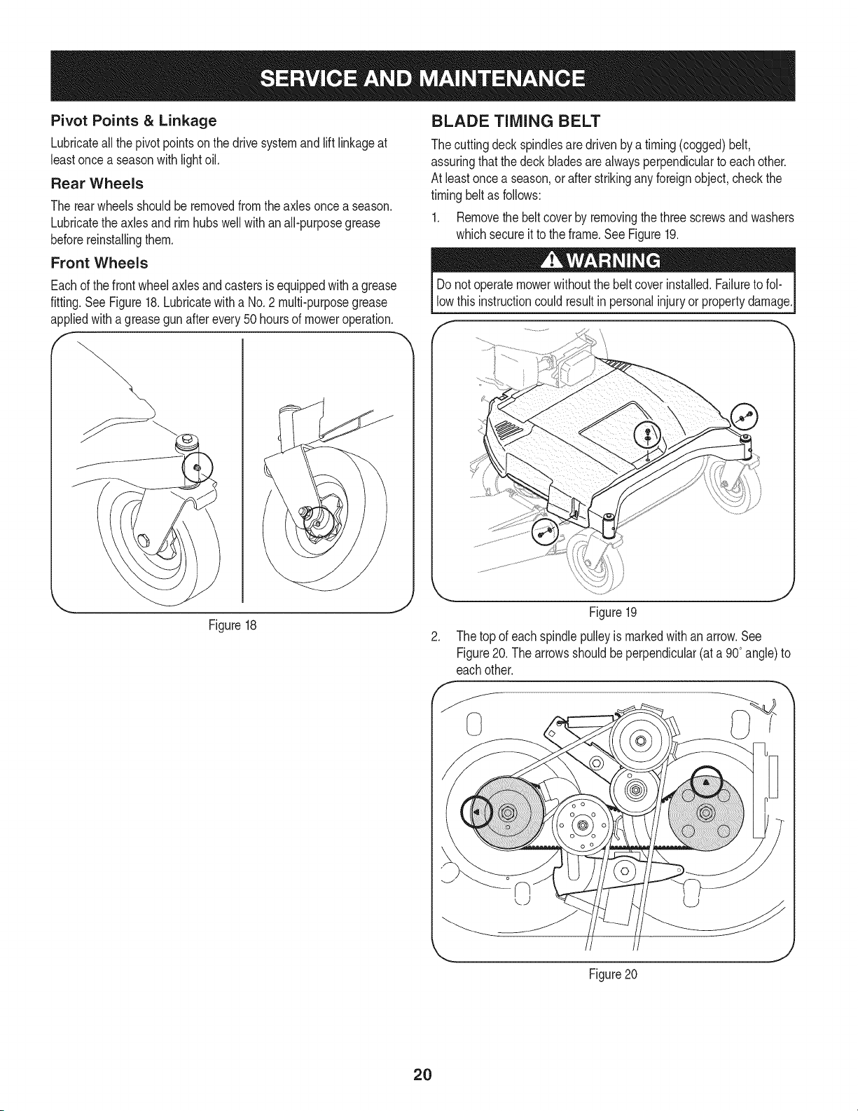
Front Wheels
Eachof the frontwheelaxlesandcastersis equippedwitha grease
fitting.See Figure18.Lubricatewitha No.2 multi-purposegrease
appliedwitha greasegun after every 50 hoursof moweroperation.
f -,
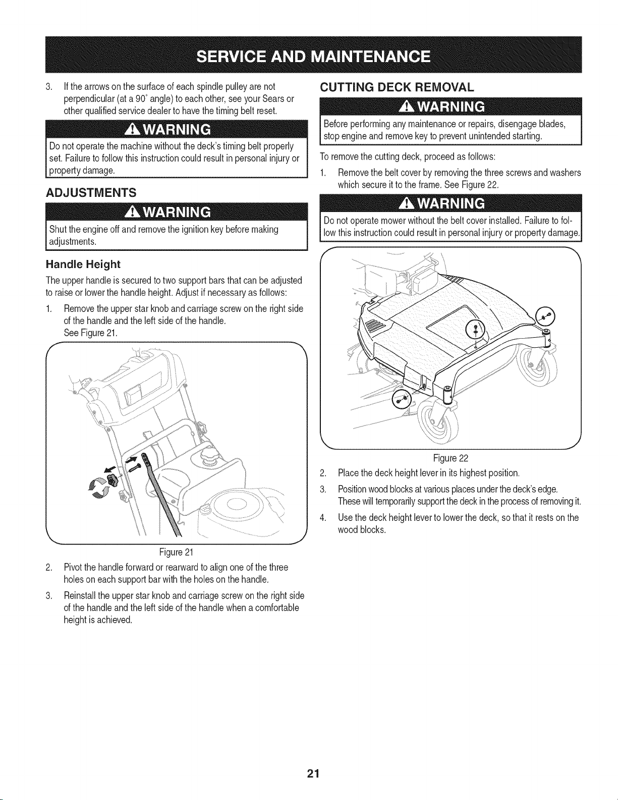
BLADE TIMING BELT
The cuttingdeckspindlesaredrivenby a timing(cogged)belt,
assuringthatthe deck bladesare alwaysperpendicularto eachother.
At leastoncea season,or after strikingany foreignobject,checkthe
timingbeltas follows:
1. Removethe beltcover by removingthethree screwsand washers
whichsecureit to the frame.SeeFigure19.
Donot operatemowerwithoutthe belt coverinstalled.Failureto fol-
low thisinstructioncould resultin personalinjuryorpropertydamage.
Figure18
Figure19
2. The topof eachspindlepulleyis markedwith an arrow.See
Figure20. Thearrowsshouldbeperpendicular(ata 90°angle)to
eachother.
Figure20
20
3. If thearrowson the surfaceof each spindlepulleyare not
perpendicular(ata 90°angle)to eachother,seeyour Searsor
otherqualifiedservicedealerto havethe timingbelt reset.
Do notoperatethe machinewithoutthe deck'stimingbelt properly
set. Failureto followthisinstructioncould resultin personalinjuryor
propertydamage.
ADJUSTMENTS
CUTTING DECK REMOVAL
Beforeperforminganymaintenanceorrepairs,disengageblades,
stopengineand removekey to preventunintendedstarting.
To removethe cuttingdeck,proceedas follows:
1. Removethe beltcover by removingthe threescrewsand washers
whichsecureit to the frame.SeeFigure22.
Shutthe engineoffand removethe ignitionkeybeforemaking
adjustments.
Handle Height
Theupperhandleis securedto two support barsthat can be adjusted
to raiseor lowerthe handleheight.Adjustif necessaryas follows:
1. Removetheupperstarknobandcarriagescrewonthe rightside
of the handleandthe left side of the handle.
SeeFigure21.
Donot operatemowerwithoutthe belt coverinstalled.Failureto fol-
low thisinstructioncould resultin personalinjuryor propertydamage.
Figure21
2. Pivotthe handleforwardor rearwardto alignone of the three
holesoneach supportbarwith the holeson the handle.
3. Reinstallthe upperstar knoband carriagescrewon the rightside
of the handleandthe left side of the handlewhena comfortable
heightis achieved.
Figure22
2. Placethe deckheightleverinits highestposition.
3. Positionwoodblocksatvariousplacesunderthe deck'sedge.
Thesewilltemporarilysupportthedeckinthe processof removingit.
4. Usethe deckheightleverto lowerthe deck, sothat it restsonthe
wood blocks.
21
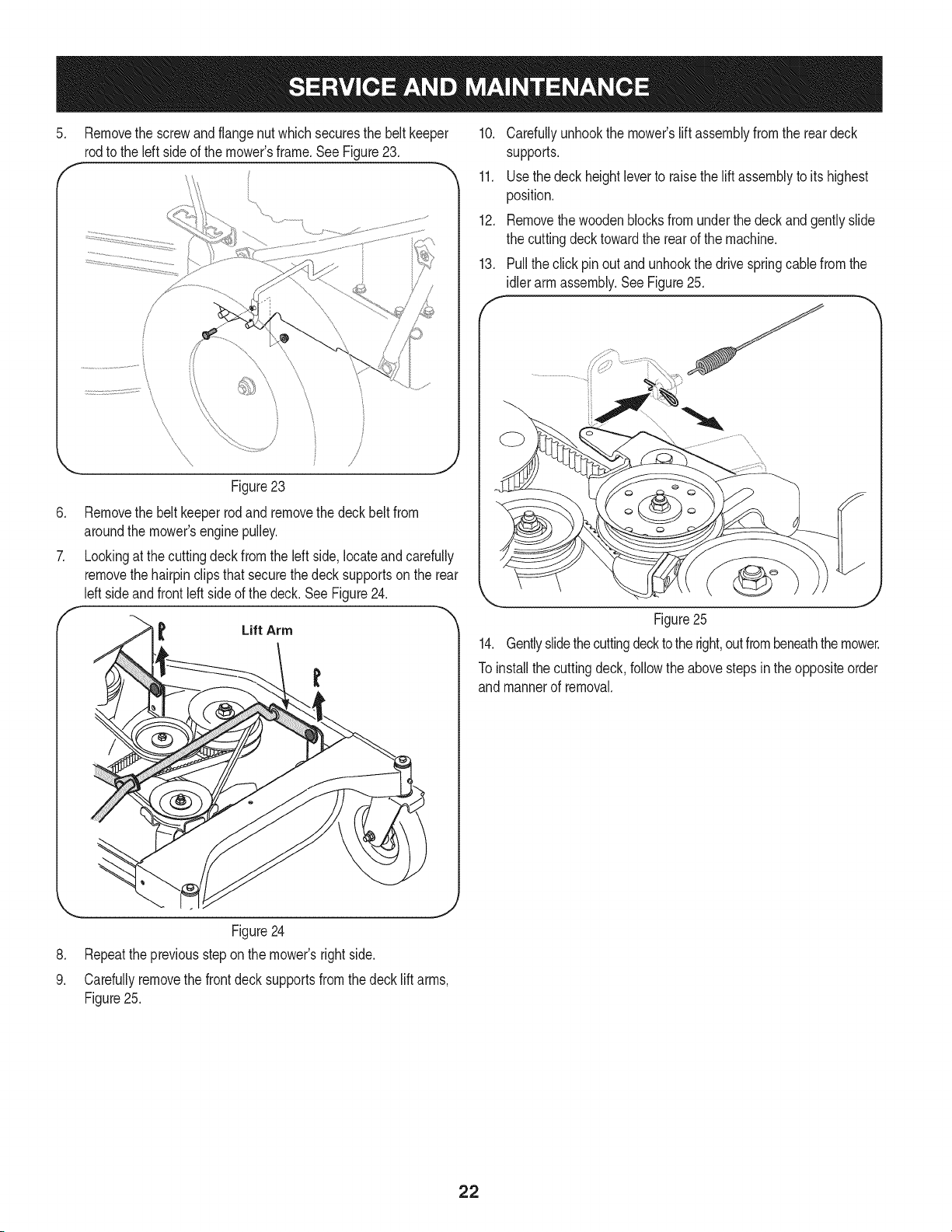
5. Removethe screwand flangenut whichsecuresthe belt keeper
rodto the left sideof the mower'sframe.SeeFigure23.
.
\
\
Figure23
Removethe beltkeeperrodand removethe deckbeltfrom
aroundthe mower'senginepulley.
Lookingat the cuttingdeckfromthe left side,locateand carefully
removethe hairpinclipsthatsecurethe deck supportson the rear
leftside andfront left sideof the deck.See Figure24.
Lift Arm
10. Carefullyunhookthe mower'slift assemblyfrom the reardeck
supports.
11. Usethe deck heightleverto raisethe lift assemblyto its highest
position.
12. Removethe woodenblocksfrom underthe deck and gentlyslide
the cuttingdecktowardthe rearof the machine.
13. Pullthe click pin out and unhookthe drivespringcablefrom the
idlerarm assembly.SeeFigure25.
Figure25
14. Gentlyslidethecuttingdeckto theright,outfrombeneaththemower.
To installthe cuttingdeck,followthe abovestepsinthe oppositeorder
and mannerof removal.
.
9.
... J
Figure24
Repeatthepreviousstepon the mower'srightside.
Carefullyremovethe frontdeck supportsfromthe decklift arms,
Figure25.
22
CUTTING BLADES
Shutthe engineoffand removeignitionkey beforeremovingthe
cutting blade(s)for sharpeningor replacement.Protectyourhandsb
usingheavygloveswhengraspingthe blade.
Periodicallyinspectthe bladeand/or spindlefor cracksor damage,
especiallyafter you've strucka foreignobject.Do notoperatethe
machineuntil damagedcomponentsare replaced.
Toremovethe blades,proceedas follows.
1. Removethedeckfrombeneaththe mower,(referto CuttingDeck
Removalearlierinthis section)thengentlyflip thedeckoverto
exposeitsunderside.
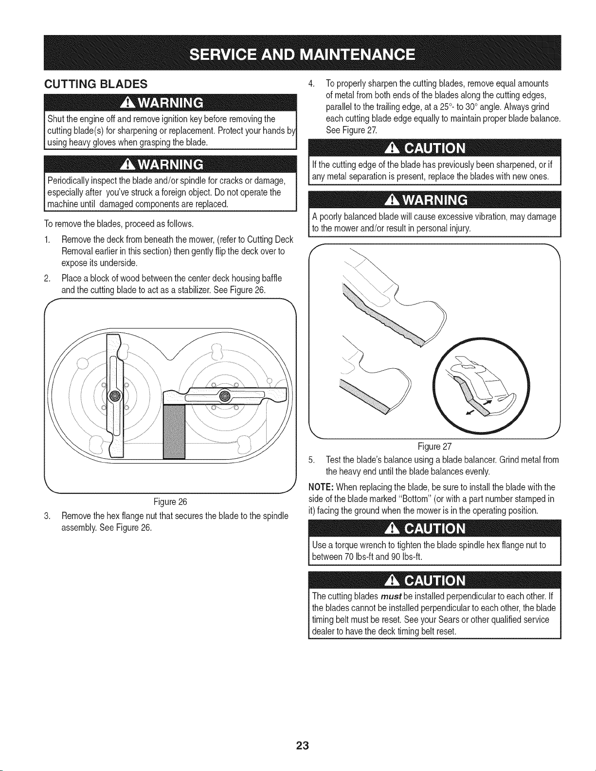
2. Placea blockof woodbetweenthe centerdeck housingbaffle
andthe cuttingbladeto act as a stabilizer.See Figure26.
F
J
Figure26
3. Removethehex flangenutthat securesthe blade to the spindle
assembly.SeeFigure26.
To properlysharpenthe cuttingblades,removeequalamounts
of metalfrombothendsof the bladesalongthe cuttingedges,
parallelto the trailingedge,at a250.to 300angle.Alwaysgrind
eachcutting bladeedgeequallyto maintainproperblade balance.
SeeFigure27.
Ifthe cuttingedgeof the bladehas previouslybeen sharpened,or if
any metalseparationis present,replacethe bladeswithnewones.
A poorlybalancedbladewill causeexcessivevibration,maydamage
to the mowerand/or resultin personalinjury.
\
Figure27
5. Testthe blade'sbalanceusinga blade balancer.Grindmetalfrom
the heavyend untilthe bladebalancesevenly.
NOTE:Whenreplacingthe blade,be sureto installthe bladewiththe
sideof the blademarked"Bottom"(orwitha part numberstampedin
it)facingthe groundwhenthe moweris inthe operatingposition.
Usea torquewrenchto tightenthe bladespindlehexflangenutto
between70Ibs-ftand 90 Ibs-ft.
Thecutting bladesmust be installedperpendicularto eachother.If
the bladescannotbe installedperpendicularto each other,the blade
timingbeltmustbe reset.SeeyourSearsorotherqualifiedservice
dealerto havethe decktimingbelt reset.
23
TRAIL SHIELD Jump Starting
Neveroperatethe mowerwithoutthe trailshieldin placeandworking.
Failureto do socan resultinpersonalinjury.
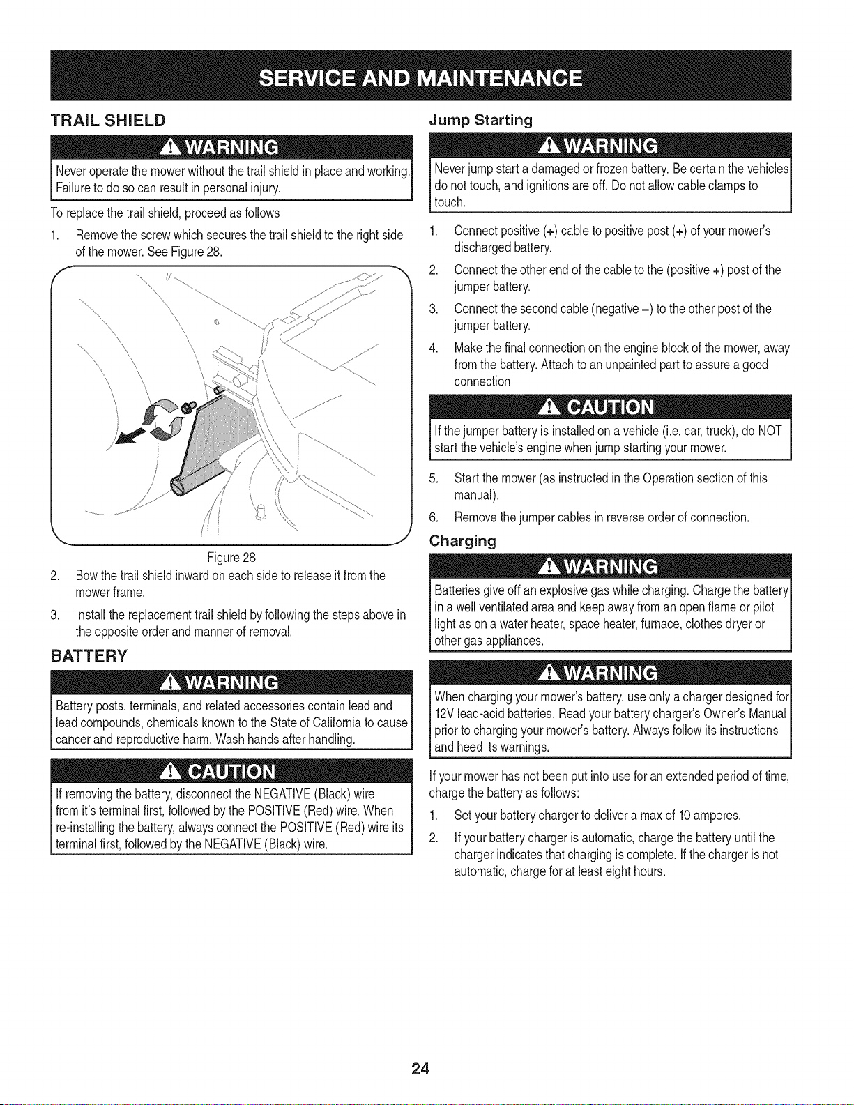
To replacethe trail shield,proceedas follows:
1. Removethe screwwhich securesthetrail shieldto the right side
of the mower.SeeFigure28.
.
.
Figure28
Bowthe trail shieldinwardoneach sideto releaseit fromthe
mowerframe.
Installthe replacementtrail shieldby followingthe stepsabovein
theoppositeorderand mannerof removal.
BATTERY
Batteryposts,terminals,andrelatedaccessoriescontain leadand
leadcompounds,chemicalsknownto the Stateof Californiato cause
cancerandreproductiveharm.Washhandsafter handling.
If removingthebattery,disconnectthe NEGATIVE(Black)wire
fromit s terminalfirst,followedbythe POSITIVE(Red)wire.When
re-installingthe battery,alwaysconnectthe POSITIVE(Red)wire its
_termna f rst,fo owedbythe NEGATVE(Back) w re.
Neverjumpstart a damagedor frozenbattery.Becertainthe vehicles
do nottouch,andignitionsare off. Do notallowcableclampsto
touch.
1. Connectpositive(+) cableto positivepost(+) of yourmower's
dischargedbattery.
2. Connecttheotherend of thecableto the (positive+) post of the
jumperbattery.
3. Connectthesecondcable (negative-) to the otherpost of the
jumperbattery.
4. Makethefinal connectionon the engineblockof the mower,away
fromthe battery.Attachto an unpaintedpartto assurea good
connection.
Ifthejumper batteryis installedona vehicle(i.e. car, truck),do NOT
start thevehicle'senginewhenjump startingyourmower.
5. Start the mower(as instructedin the Operationsectionof this
manual).
6. Removethejumpercablesin reverseorderof connection.
Charging
giveoff anexplosivegas whilecharging.Chargethe batteryI
Batteries
in a wellventilatedareaandkeepawayfrom an open flame or pilot
light as ona waterheater,spaceheater,furnace,clothesdryeror
othergas app ances, j
chargingyourmower'sbattery,useonlya chargerdesignedforI
When
12Vlead-acidbatteries.Readyourbatterycharger'sOwner'sManualI
priorto chargingyourmowers battery.Alwaysfollowits instructions I
andheed its warnings, j
Ifyourmowerhas not beenput intouse for anextendedperiodof time,
chargethe batteryas follows:
1. Set yourbatterychargerto delivera maxof 10amperes.
2. Ifyourbatterychargeris automatic,chargethebatteryuntilthe
chargerindicatesthat chargingis complete.If thechargeris not
automatic,chargefor at leasteighthours.
24
CHANGING THE DECK ENGAGEMENT BELT
Shutthe engineoffand removeignitionkey beforeremovingthe
cutting blade(s)for sharpeningor replacement.Protectyourhandsb
usingheavygloveswhengraspingbladesandpulleys.
The V-beltsfoundonyourmowerarespeciallydesignedto engageand
disengagesafely.A substitute(non-OEM)V-beltcanbedangerousby
notdisengagingcompletely.Fora properworkingmachine,useidenti-
cal replacementbeltsas listedinpartslistof thisoperator'smanual.
Allbeltson your mowerare subjectto wearand shouldbe replacedif
anysignsof weararepresent. To changeor replacethe deckengage-
mentbeltonyour mower,proceedasfollows:
1. Removethecuttingdeckfromthe moweras instructedearlier in
thissection.
Avoid pinchinginjuries.Neverplaceyourfingersonthe idlerspringor
betweenthe belt anda pulleywhile removingthebelt
2. Removethebelt coveras instructedearlier in this section.Refer
to Figure19on page22.
3. Removethebelt keeperas instructedearlierin this section.Refer
to Figure23 onpage24.
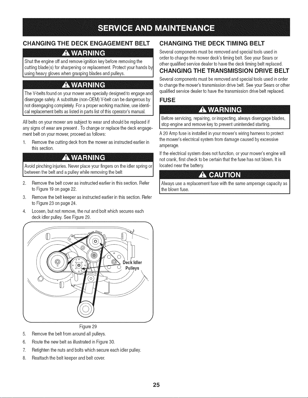
4. Loosen,butnot remove,the nutand bolt which secureseach
deckidler pulley.See Figure29.
f
CHANGING THE DECK TIMING BELT
Severalcomponentsmustbe removedand specialtoolsusedin
orderto changethe mowerdeck'stimingbelt.SeeyourSearsor
otherqualifiedservicedealerto havethe decktiming belt replaced.
CHANGING THE TRANSMISSION DRIVE BELT
Severalcomponentsmustbe removedand specialtoolsusedinorder
to changethe mower'stransmissiondrivebelt.SeeyourSearsor other
qualifiedservicedealerto havethe transmissiondrivebelt replaced.
FUSE
Beforeservicing,repairing,or inspecting,alwaysdisengageblades,
stopengineand removekey to preventunintendedstarting.
A 20 Ampfuseis installedinyour mower'swiringharnessto protect
the mower'selectricalsystemfromdamagecausedby excessive
amperage.
Ifthe electricalsystemdoes notfunction,or yourmower'senginewill
notcrank,first checkto becertainthatthe fusehas not blown.Itis
locatednearthe battery.
Alwaysuse a replacementfusewiththe sameamperagecapacityas
the blownfuse.
Deckidler
Figure29
5. Removethebelt from aroundall pulleys.
6. Routethe newbelt as illustratedin Figure30.
7. Retightenthe nuts and bolts which secureeach idler pulley.
8. Reattachthe belt keeperand belt cover.
J
25
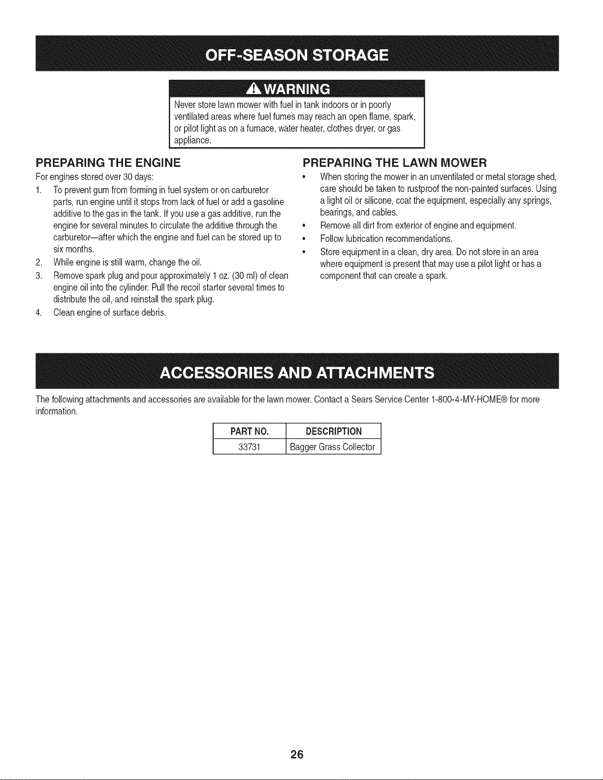
Neverstorelawnmowerwithfuel intankindoorsor in poorly
ventilatedareaswherefuel fumesmayreachan openflame,spark,
or pilot lightas ona furnace,waterheater,clothesdryer,or gas
appliance.
PREPARING THE ENGINE
Forenginesstoredover30days:
1. Topreventgum from formingin fuel systemor on carburetor
parts,runengineuntilit stopsfromlackof fuel oradda gasoline
additiveto thegas in thetank. If youuse agas additive,runthe
enginefor severalminutesto circulatethe additivethroughthe
carburetor--afterwhichthe engineandfuel canbe storedup to
sixmonths.
2. Whileengineis still warm,changethe oil.
3. Removesparkplug and pour approximately1 oz. (30 rnl) of clean
engineoil intothe cylinder.Pullthe recoilstarterseveraltimesto
distributetheoil, and reinstallthe sparkplug.
4. Cleanengineof surfacedebris.
PREPARING THE LAWN MOWER
• Whenstoringthe mowerinan unventilatedor metalstorageshed,
careshouldbetakento rustproofthe non-paintedsurfaces.Using
a lightoil or silicone,coatthe equipment,especiallyany springs,
bearings,andcables.
• Removealldirt from exteriorof engineandequipment.
• Followlubricationrecommendations.
• Storeequipmentina clean,dry area.Do notstoreinan area
whereequipmentis presentthat mayuse a pilotlightor has a
componentthatcan createa spark.
Thefollowingattachmentsandaccessoriesareavailablefor the lawnmower.Contacta SearsServiceCenter1-800-4-MY-HOME®for more
information.
PARTNO. DESCRIPTION
33731 BaggerGrassCollector
26
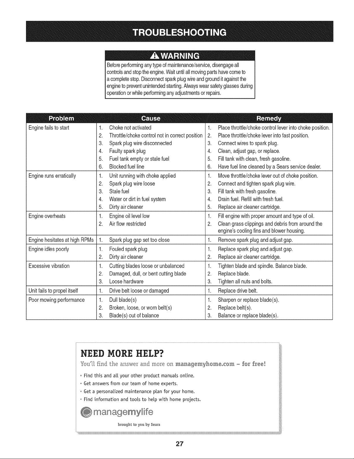
Beforeperforminganytyped maintenance/service,disengageall
controlsandstoptheengine.Waituntilallmovingpartshavecometo
a completestop.Disconnectsparkplugwireandgroundit againstthe
engineto preventunintendedstarting.Alwayswearsafetyglassesduring
operationorwhileperforminganyadjustmentsorrepairs.
Enginefailsto start
Enginerunserratically
1. Chokenotactivated
2. Throttb/chokecontrolnot in correctposition
3. Sparkplugwire disconnected
4. Faultysparkplug
5. Fueltank emptyor stale fuel
6. Blockedfuel line
1. Unit runningwith choke applied
2. Sparkplugwire loose
3. Stalefuel
4. Wateror dirt in fuel system
5. Dirtyair cleaner
1. Engineoil levellow
2. Air flow restricted
Engineoverheats
Enginehesitatesat high RPMs 1. Sparkpluggap settoo close 1.
Engineidlespoorly 1. Fouledspark plug 1.
2. Dirtyair cleaner 2.
Excessivevibration 1. Cuttingbladeslooseor unbalanced 1.
2. Damaged,dull,or bentcuttingblade 2.
3. Loosehardware 3.
Unitfailsto propelitself 1. Drivebelt looseor damaged 1.
Poormowingperformance 1. Dullblade(s) 1.
2. Broken,loose,or wornbelt(s) 2.
3. Blade(s)out of balance 3.
1. Placethrottle/chokecontrol leverinto chokeposition.
2. Placethrottle/chokeleverintofast position.
3. Connectwires to sparkplug.
4. Clean,adjustgap,or replace.
5. Filltank with clean,fresh gasoline.
6. Havefuel line cleanedby a Searsservicedealer.
1. Movethrottle/chokeleverout d choke position.
2. Connectand tightenspark plugwire.
3. Filltank with fresh gasoline.
4. Drainfuel. Refillwithfreshfuel.
5. Replaceair cleanercartridge.
1. Fillenginewith properamountand type of oil.
2. Cleangrass clippingsand debrisfrom aroundthe
engine'scoolingfinsandblowerhousing.
Removesparkplugand adjustgap.
Replacesparkplug and adjustgap.
Replaceair cleanercartridge.
Tightenbladeand spindle.Balanceblade.
Replaceblade.
Tightenall nuts and bolts.
Replacedrive belt.
Sharpenor replaceblade(s).
Replacebelt(s).
Balanceor replaceblade(s).
NEED MORE HELP?
Y.ouq],findthe m_swe__and moK_ On managemyhememem - £e_' free!
o Hnd this and all your other product manuals online.
o Get answers from our team of home experts.
o Get a personalized maintenance pLan for your home.
o Find information and tools to help with home projects.
breugh_ te you by SeaTs
27
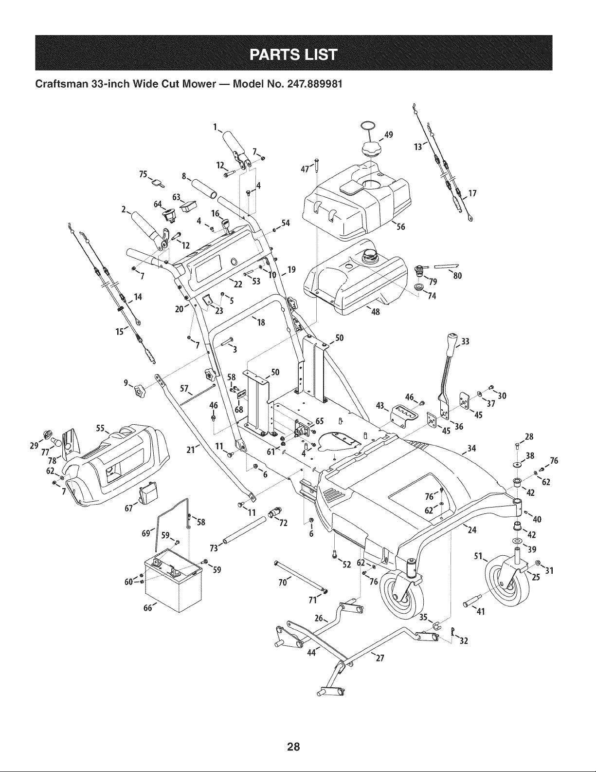
Craftsman 33=inch Wide Cut Mower B Model No. 247.889981
5O
5O
33
34
28
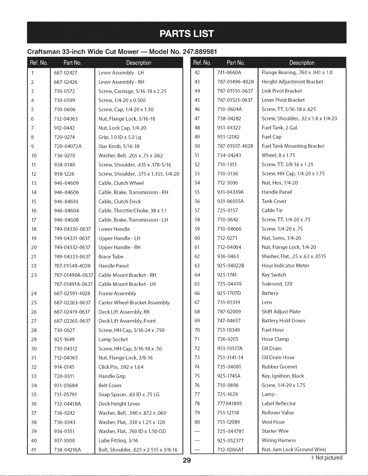
Craftsman 33-inch Wide Cut Mower B Model No. 247.889981
m
1
2
3
4
5
6
7
8
9
10
11
12
13
14
15
16
17
18
19
20
21
22
23
24
25
26
27
28
29
30
31
32
33
34
35
36
37
38
39
40
41
687-02427
687-02426
710-0572
710-0599
710-0606
712-04063
912-0442
720-0274
720-04072A
736-0270
938-0140
938-1226
946-04609
946-04606
946- 04610
946-04604
946-04608
749-04330-0637
749-04331-0637
749-04332-0637
749-04333-0637
787-01548-4028
787-01490A-0637
787-01491A-0637
687-02591-4028
687-02263-0637
687-02419-0637
687-02265-0637
710-0627
925-1649
710-04312
712-04065
914-0145
720-0311
931-05684
731-05791
732-04418A
736-0242
736-0343
936-0351
937-3000
738-04216A
Lever Assembly - LH
Lever Assembly - RH
Screw, Carriage, 5/16-18 x 2.25
Screw, 1/4-20 x 0.500
Screw, Cap, 1/4-20 x 1.50
Nut, Flange Lock, 5/16-18
Nut, Lock Cap, 1/4-20
Grip, 1.0 ID x 5.0 Lg
Star Knob, 5/16-18
Washer, Bell, .265 x .75 x .062
Screw, Shoulder, .435 x .178-5/16
Screw, Shoulder, .375 x 1.355, 1/4-20
Cable, Clutch Wheel
Cable, Brake, Transmission - RH
Cable, Clutch Deck
Cable, Throttle/Choke, 38 x 1.1
Cable, Brake, Transmission - LH
Lower Handle
Upper Handle - LH
Upper Handle - RH
Brace Tube
Handle Panel
Cable Mount Bracket- RH
Cable Mount Bracket- LH
Frame Assembly
Caster Wheel Bracket Assembly
Deck Lift Assembly, RR
Deck Lift Assembly, Front
Screw, HH Cap, 5/16-24 x .750
Lamp Socket
Screw, HH Cap, 5/16-18 x .50
Nut, Flange Lock, 3/8-16
Click Pin, .092 x 1.64
Handle Grip
Belt Cover
Snap Spacer, .63 ID x .75 LG
Deck Height Lever
Washer, Bell, .340 x .872 x .060
Washer, Flat, .330 x 1.25 x .120
Washer, Flat, .760 ID x 1.50 OD
Lube Fitting, 3/16
Bolt, Shoulder, .625 x 2.515 x 3/8-16
29
m
m
42
43
44
45
46
47
48
49
5O
51
52
53
54
55
56
57
58
59
6O
61
62
63
64
65
66
67
68
69
7O
71
72
73
74
75
76
77
78
79
8O
741-0660A
787-01496-4028
787-01510-0637
787-01521-0637
710-0604A
738-04282
951-04322
951-12182
787-01507-4028
Flange Bearing, .760 x .941 x 1.0
Height Adjustment Bracket
Link Pivot Bracket
Lever Pivot Bracket
Screw, TT, 5/16-18 x .625
Screw, Shoulder, .32 x 1.8 x 1/4-20
Fuel Tank, 2 Gal.
Fuel Cap
Fuel Tank Mounting Bracket
734-04243
710-1315
710-0136
712-3006
931-04339A
931-06935A
725-0157
710-0642
710-04666
712-0271
712-04064
936-0463
925-04022B
925-1741
725-04439
925-1707D
731-05319
787-02009
747-04657
751-10349
726-0205
951-I0517A
751-3141-14
735-04081
925-1745A
710-0896
725-1629
777X41805
751-12118
751-12089
725-04478t
925-05237t
712-0266At
Wheel, 8 x 1.75
Screw, TT, 3/8-16 x 1.25
Screw, HH Cap, 1/4-20 x 1.75
Nut, Hex, 1/4-20
Handle Panel
Tank Cover
Cable Tie
Screw, TT, 1/4-20 x .75
Screw, 1/4-20 x .75
Nut, Sems, 1/4-20
Nut, Flange Lock, 1/4-20
Washer, Flat, .25 x .63 x .0515
Hour Indicator Meter
Key Switch
Solenoid, 12V
Battery
Lens
Shift Adjust Plate
Battery Hold Down
Fuel Hose
Hose Clamp
Oil Drain
Oil Drain Hose
Rubber Gromet
Key, Ignition, Black
Screw, 1/4-20 x 1.75
Lamp
Label Reflector
Rollover Valve
Vent Hose
Sta rte r Wi re
Wiring Harness
Nut, Jam Lock (Ground Wire)
t- Notpictured
Craftsman 33=inch Wide Cut Mower- Model No. 247.889981
13
12
12
10
38
72
4
1"34
14
60
41
47
55
51
3O
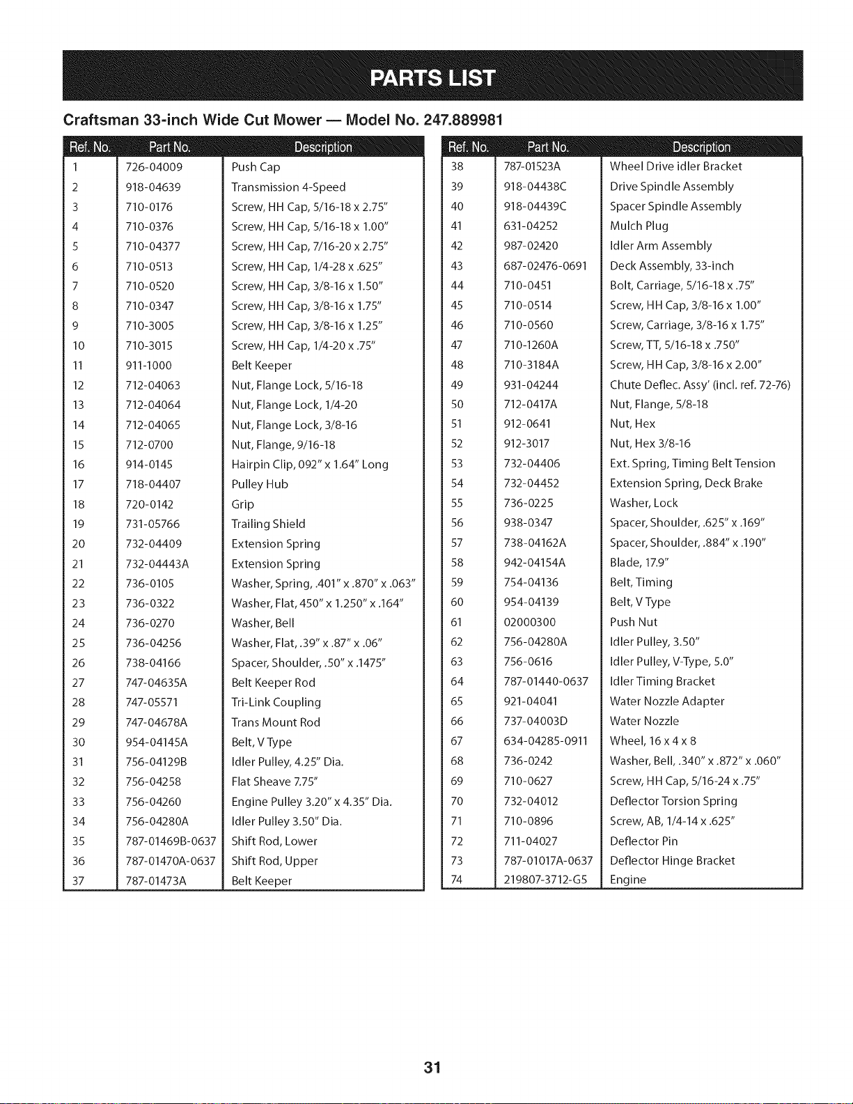
Craftsman 33-inch Wide Cut Mower B Model No. 247.889981
I
2
3
4
5
6
7
8
9
10
11
12
13
14
15
16
17
18
19
20
21
22
23
24
25
26
27
28
29
30
31
32
33
34
35
36
37
726-04009
918-04639
710-0176
710-0376
710-04377
710-0513
710-0520
710-0347
710-3005
710-3015
911-I000
712-04063
712-04064
712-04065
712-0700
914-0145
718-04407
720-0142
731-05766
732-04409
732-04443A
736-0105
736-0322
736-0270
736-04256
738-04166
747-04635A
747-05571
747-04678A
954-04145A
756-041298
756-04258
756-04260
756-04280A
787-01469B-0637
787-01470A-0637
787-01473A
Push Cap
Transmission 4-Speed
Screw, HH Cap, 5116-18 x 2.75"
Screw, HH Cap, 5/16-18 x 1.00"
Screw, HH Cap, 7/16-20 x 2.75"
Screw, HH Cap, 1/4-28 x .625"
Screw, HH Cap, 3/8-16 x 1.50"
Screw, HH Cap, 3/8-16 x 1.75"
Screw, HH Cap, 3/8-16 x 1.25"
Screw, HH Cap, 1/4-20 x .75"
Belt Keeper
Nut, Flange Lock, 5/16-18
Nut, Flange Lock, 1/4-20
Nut, Flange Lock, 3/8-16
Nut, Flange, 9/16-18
Hairpin Clip, 092" x 1.64" Long
Pulley Hub
Grip
Trailing Shield
Extension Spring
Extension Spring
Washer, Spring, .401" x .870" x .063"
Washer, Flat, 450" x 1o250" x o164"
Washer, Bell
Washer, Flat, .39" x .87" x .06"
Spacer, Shoulder, .50" x .1475"
Belt Keeper Rod
Tri-Link Coupling
Trans Mount Rod
Belt, V Type
tdter guttey, 4.25" Oia.
Flat Sheave 7.75"
Engine Pulley 3.20" x 4.35" Dia.
Idler Pulley 3.50" Dia.
Shift Rod, Lower
Shift Rod, Upper
Belt Keeper
38
39
4O
41
42
43
44
45
46
47
48
49
50
51
52
53
54
55
56
57
58
59
6O
61
62
63
64
65
66
67
68
69
70
71
72
73
74
787-01523A
918-04438C
918-04439C
631-04252
987-02420
687-02476-0691
710-0451
710-0514
710-0560
710-1260A
710-3184A
931-04244
712-0417A
912-0641
912-3017
732-04406
732-04452
736-0225
938-0347
738-04162A
942- 04154A
754-04136
954-04139
02000300
756-04280A
756-0616
787-01440-0637
921-04041
737-04003D
634-04285-0911
736-0242
710-0627
732-04012
710-0896
711-04027
787-01017A-0637
219807-3712-G5
D = I! 0
Wheel Drive idler Bracket
Drive Spindle Assembly
Spacer Spindle Assembly
Mutch Ptug
Idler Arm Assembly
Deck Assembly, 33-inch
Bolt, Carriage, 5/16-18 x .75"
Screw, HH Cap, 3/8-16 x 1.00"
Screw, Carriage, 3/8-16 x 1.75"
Screw, TT, 5/16-18 x .750"
Screw, HH Cap, 3/8-16 x 2.00"
Chute Deflec. Assy' (incl. refl 72-76)
Nut, Flange, 5/8-18
Nut, Hex
Nut, Hex 3/8-16
Ext. Spring, Timing Belt Tension
Extension Spring, Deck Brake
Washer, Lock
Spacer, Shoulder, .625" x .169"
Spacer, Shoulder, .884" x .190"
Blade, 1Z9"
Belt, Timing
Belt, V Type
Push Nut
Idler Pulley, 3.50"
Idler Pulley, V-Type, 5.0"
Idler Timing Bracket
Water Nozzle Adapter
Water Nozzle
Wheel, 16x4x 8
Washer, Bell, .340" x .872" x .060"
Screw, HH Cap, 5/16-24 x .75"
Deflector Torsion Spring
Screw, AB, 1/4-14 x .625"
Deflector Pin
Deflector Hinge Bracket
Engine
31
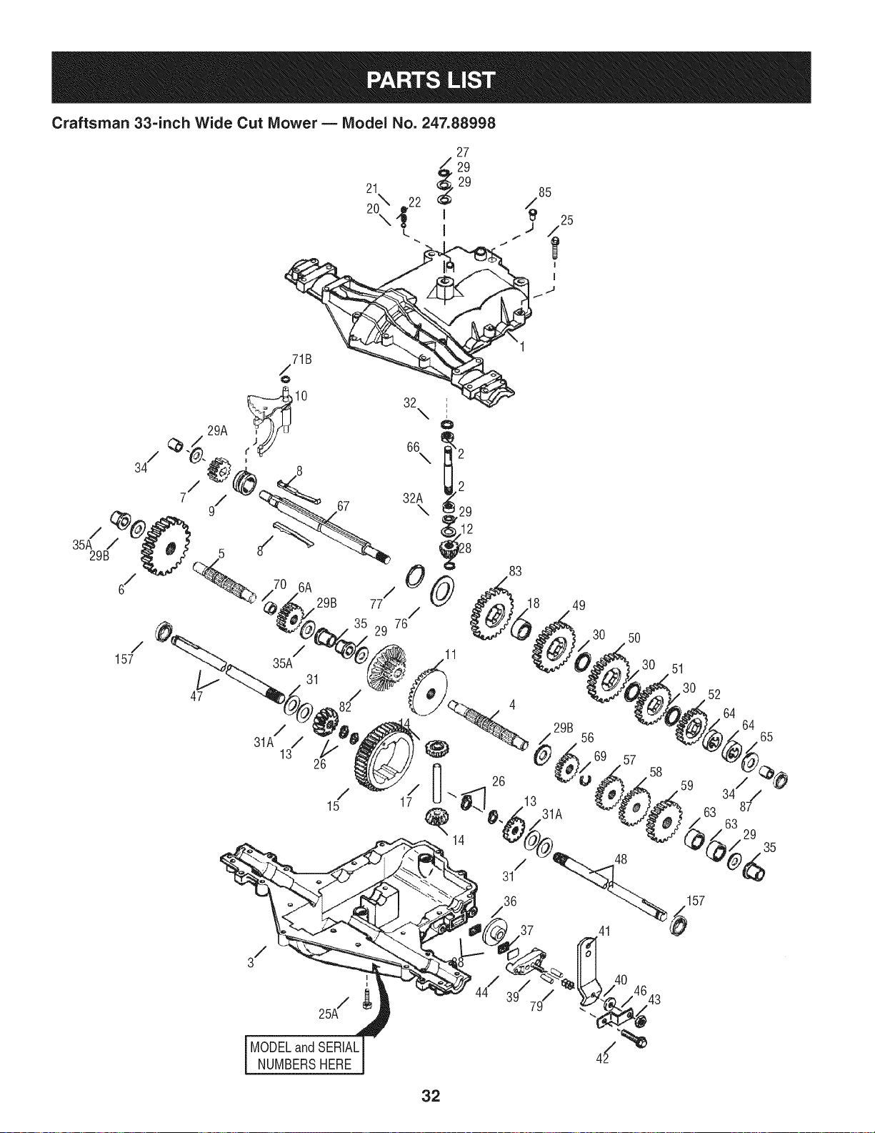
Craftsman 33=inch Wide Cut Mower m Model No. 247.88998
29A
67
29B
/
157
47
6A
8/
26
/
15
/
35A
31
/
31A /
13
MODELandSERIAL
NUMBERSHERE
37 41
40
157
32

Craftsman 33-inch Wide Cut Mower B Model No. 247.88998
D = O O
TC-772147 TransaxleCover
2 TC-780086A NeedleBearing
3 TC-770128A TransaxleCase
4 TC-776395 Countershaft
5 TC-776409 OutputShaft
6 T0-778364 SpurGear(38T-PM/SER)
6A T0-778369 SpurGear(15T-PM/SER)
7 T0-778330 SpurGear(11T-PM/SER)
8 TC-792180A Shift KeySet (Qty.2)
9 TC-784352 ShiftCollar
10 TC-784378 ShiftRod& ForkAssembly
11 TC-778334 BevelGear(30T-PM)
12 TC-778309 InputBevelPinion(13T-PM)
13 TC-778368 BevelGear13T(Incl. ref.13& 14)
14 TC-778368 BevelGear13T(Incl. ref.13& 14)
15 TC-778370 RingGear(43T)
17 TC-786188 DrivePin
18 TC-786102 Spacer(1.130"x .695")
20 TC-792077A Ball (StainlessSteel5/16"dia.)
21 TC-792211 Screw,3/8-16x 3/8"
22 TC-792079 Spring
25 TC-792073A Screw,1/4-20x 1-1/4"
25A TC-792177 Screw,1/4-20x 1-3/8"
26 TC-792125 RetainingRing-packageof 2
27 TC-792035 RetainingRing
28 TC-788040 RetainingRing
29 TC-780072 Washer.627"ID.031"
29A TC-780160 ThrustWasher(.563"ID x .031")
29B TC-780051 ThrustWasher(.762"IDX .031")
30 T0-780108 ShiftWasher(Cupped)
31 TC-780001 Washer.750"ID .56"
31A TC-780195 Washer.750"ID .062
32 TC-788083 OilSeal5/8"
32A TC-792001 O Ring(.823"OD)
34 TC-780194 Bushing(.563")
35 TC-780193 FlangedBushing(.625"ID)
35A TC-780197 FlangedBushing(.751"ID)
TC-790075 BrakeDisk
37 TC-790007 BrakePadPlate
38 TC-799021A BrakePad (pkg.of 2)
39 TC-786026 DowelPin.3125"x .750"
40 736-3078 Washer.312"ID.059"
41 TC-790104 BrakeLever
42 TC-792177 Screw1/4-20x 1-3/8"
43 912-0237 LockNut5/16-24
44 TC-790025 BrakePadHolder
46 TC-786086 Bracket
47 T0-775146 Axle (10.719"long)(Incl.26)
48 T0-775147 Axle (15.312"long)(Incl.26)
49 TC-778338 SpurGear(27T-PM/IC)
50 TC-778342 SpurGear(22T-PM/IC)
51 TC-778313 SpurGear(19T-PM/IC)
52 TC-778350 SpurGear(16T-PM/IC)
56 TC-778337 SpurGear(13T-PM/SER)
57 TC-778341 SpurGear(18T-PM/SER)
58 TC-778351 SpurGear(21T-PM/SER)
59 TC-778349 SpurGear(24T-PM/SER)
63 TC-786071 CountershaftSpacer1-1/8"x 3/8"
64 TC-786072 BrakeShaftSpacer1-3/8"x 3/8"
65 TC-780189 Washer.563" ID.062
66 TC-776472 inputShaft
67 TC-776396 BrakeShaft
69 TC-792170 RetainingRing(.75"x .042")
70 TC-786187 Spacer(.890")
71B TC-788092 O-Ring
76 TC-780090 FiatWasher(1.128"IDx .058")
77 TC-788078A RetainingRing(1.125"x .050")
79 TC-792144 Spring
82 TC-778333 Bevel(30T)& SpurGear
83 TC-778338 SpurGear(27T-PM/IC)
85 TC-792154 OilFill Plug
87 TC-788089A Oil Seal9/16" ID
157 TC-788088A Oil Seal3/4" ID
33
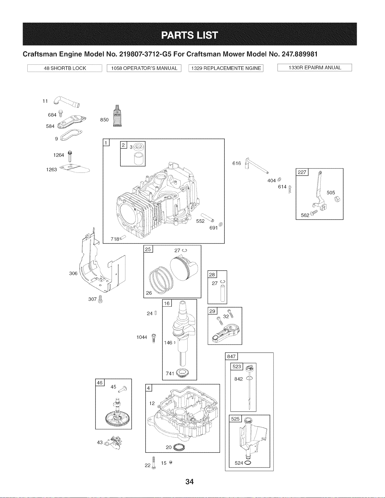
Craftsman Engine Model No. 219807=3712=G5 For Craftsman Mower Model No. 247.889981
40SHORTB,OOKI 10_0OPERATO_SMANUA,I I132_EP'AO_M_NT_I_I _3_0_E_I_U_,
11
850
@
307 _.
24
1044
D
,_,__:q,_
741 _
200
691
|
616
404 0
842 *,i_¢
524 0
614 /_
505
34
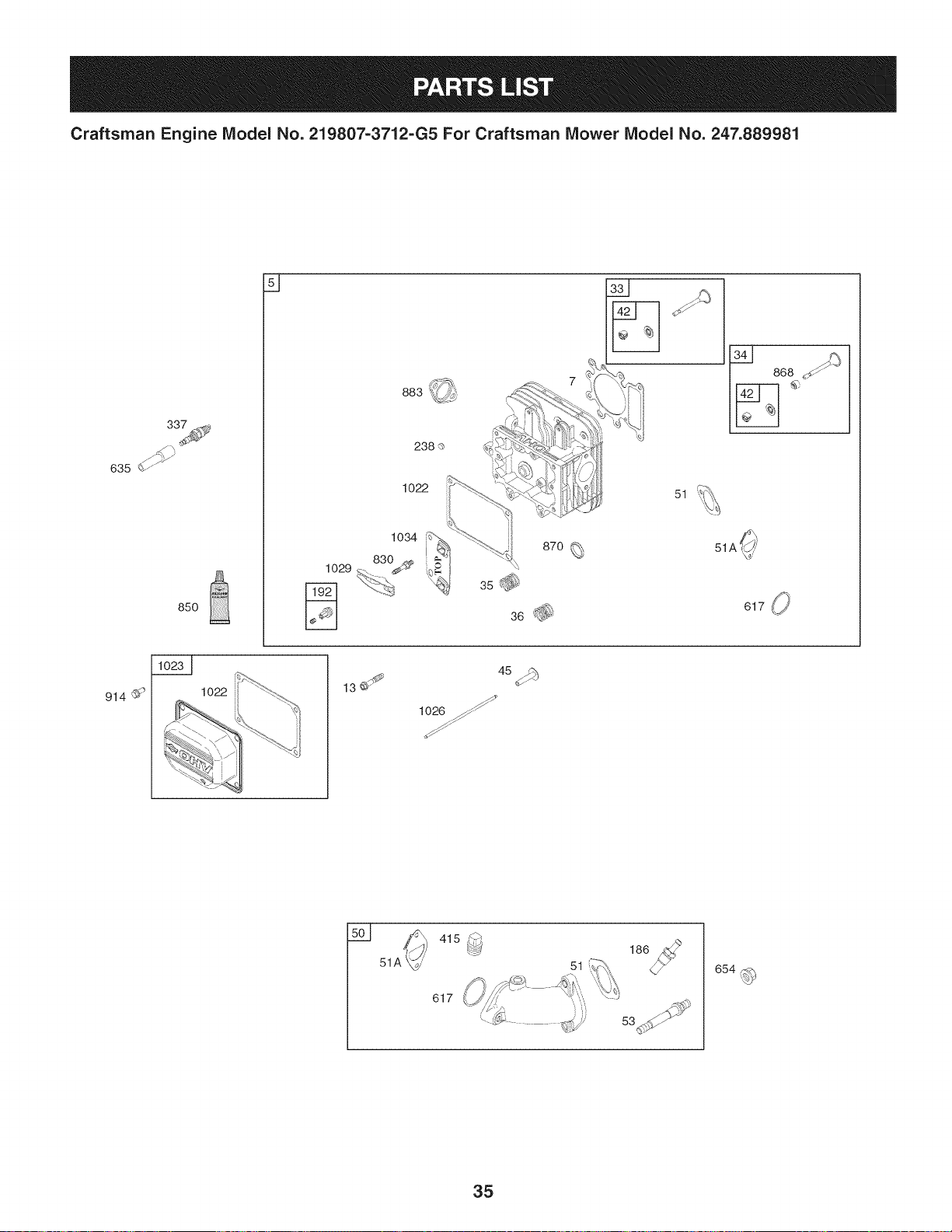
Craftsman Engine Model No. 219807=3712=G5 For Craftsman Mower Model No. 247.889981
635 _
850
914
1022
238 o
1022
L
868
1034
870
830
1029
3s_
51A _,,'
j_
lO2O_
415 s_
617
186
51
53
35
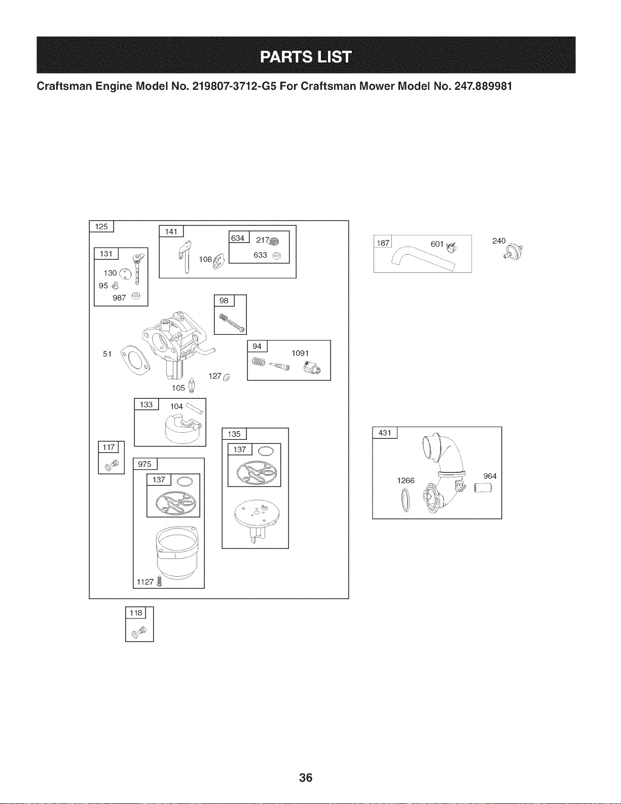
Craftsman Engine Model No. 219807=3712=G5 For Craftsman Mower Model No. 247.889981
130_U
95 '8
987 _
lO6_
51 1091
127 0
lO2
104
1127
24O
1266
964
/
/
36
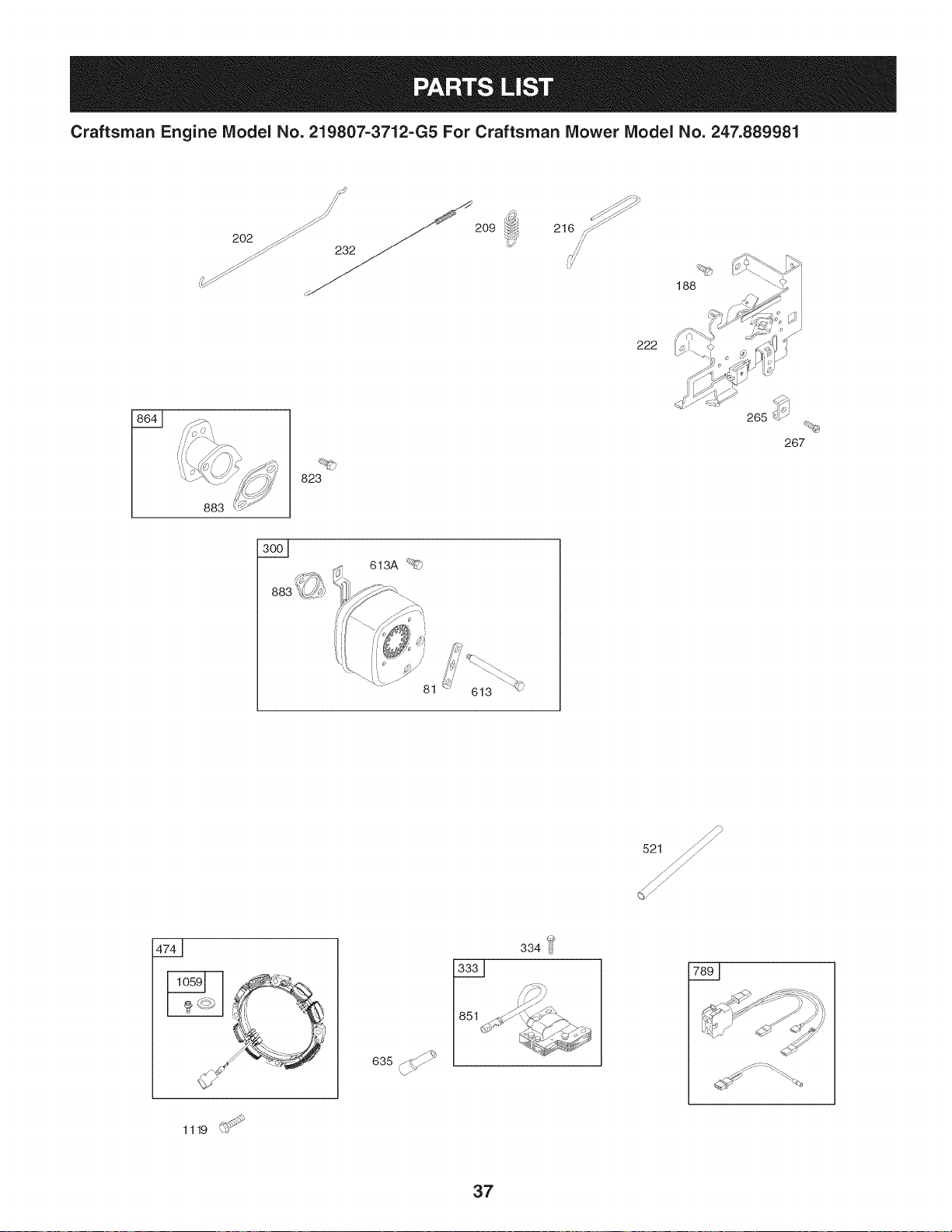
Craftsman Engine Model No. 219807-3712-G5 For Craftsman Mower Model No. 247.889981
202 ._ _ 209
-_ 232
216 ,!_"
222
188
883
3001
823
613A _
,/
81
613
1119 _:r
z_
635 J "
334
,')_Y
|
37
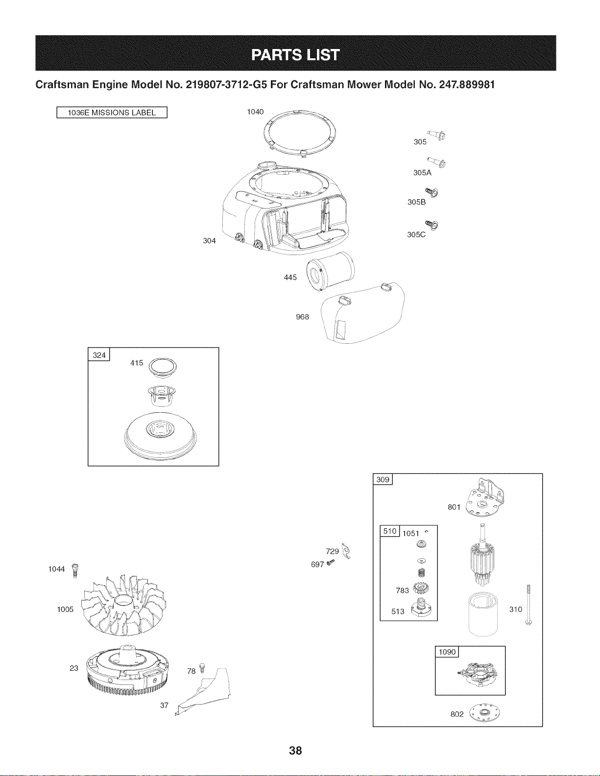
Craftsman Engine Model No. 219807-3712-G5 For Craftsman Mower Model No. 247.889981
I 1036E MISSIONS LABEL I 1040
305
3O4
305A
305B
305C
445
415
968
/
//
.... ./...¸
1044
1005
23
" '__ 3' "_Y \.h
t_J'-- _ Y- V
y I_-_h.'\;,/
78 _ F,
37 /_ "J ......
510_1051
0
@
783 _h
513
801
802
310
38
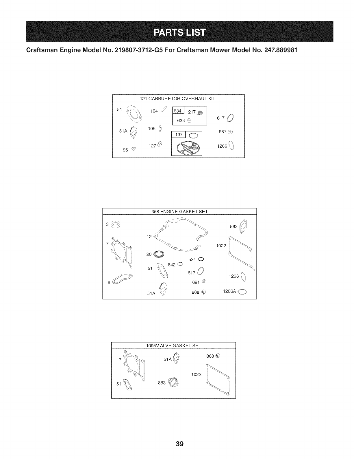
Craftsman Engine Model No. 219807=3712=G5 For Craftsman Mower Model No. 247.889981
51
121 CARBURETOR OVERHAUL KiT
104 _'
51A _ 105
127 _._?
95 _
633 _
_o
@
617 0
987 r_
3 k_._4
358 ENGINE GASKET SET
12 _.\ /{°_
...._ _.__
20@
524 0
842 @
51
617 O
1022
691
868_
51A _'
883
1266 _,
1266A @
51
1095V ALVE GASKET SET
868_)
51A'
1022
39

Or
697377 CylinderAssembly
2 797673 Kit-Bushing/Seal(MagnetoSide)
3 391086s SeaI-Oil(MagnetoSide)
4 697106 Sump-Engine
5 796183 Head-Cylinder
7 273280s Gasket-CylinderHead
9 697109 Gasket-Breather
11 794683 Tube-Breather
12 697110 Gasket-Crankcase
13 690360 Screw (CylinderHead)
15 690946 Plug-OilDrain
16 796146 Crankshaft
20 795387 Seal-Oil(PTOSide)
22 692125 Screw(CrankcaseCover/Sump)
23 698281 Flywheel
24 796335 Key-Flywheel(Steel)
25 797009 PistonAssembly(Standard)
797010 PistonAssembly(.020"Oversize)
26 797011 RingSet(Standard)
797012 RingSet(.020"Oversize)
27 698469 Lock-PistonPin
28 797013 Pin-Piston
29 791633 Rod-Connecting
32 791118 Screw(ConnectingRod)
33 791934 Valve-Exhaust
34 791935 Valve-Intake
35 691279 Spring-Valve(intake)
36 691279 Spring-Valve(Exhaust)
37 697352 Guard-Flywheel
42 499586 Keeper-Valve
43 691968 Slinger-Governor/Oil
45 690564 Tappet-Valve
46 793880 Camshaft
48 697740 Short Block
50 591245 Manifold-Intake
51 692137 Gasket-intake
51A 796081 Gasket-intake
53 591260 Stud (Carburetor)
78 691693 Screw (FlywheelGuard)
81 691178 Lock-MufflerScrew
94 793610 Kit-IdleMixture
4O
Screw(ThrottleValve)
98 695408 Kit-idleSpeed
104 694918 Pin-FloatHinge
105 696136 Valve-FloatNeedle
108 698773 Valve-Choke
117 796079 Jet-Main(Standard)
118 698788 Jet-Main(HighAltitude)
121 796184 Kit-CarburetorOverhaul
125 590399 Carburetor
127 690727 Plug-Welch
130 698774 Valve-Throttle
131 698776 Kit-ThrottleShaft
133 694914 Float-Carburetor
135 698780 Tube-FuelTransfer
137 698781 Gasket-FloatBowl
141 698778 Kit-ChokeShaft
146 691639 Key-Timing
186 794873 Connector-Hose(intake Manifold)
187 791766 Line-Fuel(Cutto RequiredLength)
188 691693 Screw(ControlBracket)
192 691986 Adjuster-RockerArm
202 691841 Link-MechanicalGovernor
209 792813 Spring-Governor(Brown)
216 691840 Link-Governor
217 695409 Spring-ChokeReturn
222 694042 Bracket-Control
227 691374 Lever-GovernorControl
232 691842 Spring-GovernorLink
238 691843 Cap-Valve
240 394358s Filter-Fuel
265 691024 Clamp-Casing
267 794904 Screw(CasingClamp)
300 796000 Muffler
304 799012 Housing-Blower
305 799370 Screw(BlowerHousing)(1/4-20x.90)
305A 697102 Screw(BlowerHousing)(1/4-20xl.20)
305B 793376 Screw(BlowerHousing)(1/4-20x.81)
3050 795891 Screw(BlowerHousing)(#10-16x.44)
306 697359 Shield-Cylinder
307 691693 Screw(CylinderShield)
309 693551 Motor-Starter

Craftsman Engine Model No. 219807=3712=G5 For Craftsman Mower Model No. 247.889981
Screw(StarterMotor)
324 796308 Screen/CupAssembly
333 799650 Armature-Magneto
334 691061 Screw (MagnetoArmature)
337 491055s Plug-Spark
358 796181 GasketSet-Engine
404 691691 Washer(GovernorCrank)
415 794129 Plug(RotatingScreen)
415A 794903 Plug(IntakeManifold)
431 797901 Elbow-Intake
445 796032 Filter-AirCleanerCartridge
474 696459 Alternator
505 691251 Nut(GovernorControlLever)
510 693699 Drive-Starter
513 692024 Clutch-Drive
521 690581 Shield-Cable
523 699908 Dipstick
524 691032 Seal-DipstickTube
525 697184 Tube-Dipstick
552 697144 Bushing-GovernorCrank
562 691119 Bolt(GovernorControlLever)
584 794682 Cover-BreatherPassage
601 791850 Hose-Clamp(Green)
613 691416 Screw (Muffler)(5/16x4.1)
613A 691678 Screw (Muffler)(5/16x.62)
614 691620 Pin-Cotter(GovernorCrank)
616 692012 Crank-Governor
617 692138 SeaI-ORing(intake Manifold)(Red)
633 699813 Seal-Choke/ThrottleShaft (ChokeShaft)
634 698779 Spring/SealAssembly(ChokeShaft)
635 691909 Boot-SparkPlug
654 690958 Nut(Carburetor)
684 697157 Screw (BreatherPassageCover)
691 692407 Seal-GovernorShaft
697 791680 Screw(DriveCap)
718 690959 Pin-Locating
729 691224 Clip-Wire
741 697128 Gear-Timing
783 693713 Gear-Pinion
789 698329 Harness-Wiring
801 691283 Cap-Drive
41
Cap-End
823 698941 Screw(MufflerAdapter)
830 691095 Stud-RockerArm
842 691031 SeaI-ORing (DipstickTube)
847 790442 Dipstick/TubeAssembly
850 100106 Sealant-Liquid
851 692424 Terminal-SparkPlug
864 796002 Adapter-Muffler
868 690968 Seal-Valve
870 691844 Seat-Valve
883 692236 Gasket-Exhaust
914 691108 Screw(RockerCover)
964 799159 Cap-Connector
968 799016 Cover-AirCleaner
975 698783 Bowl-Float
987 698777 Seal-ThrottleShaft
1005 796082 Fan-Flywheel
1022 272475s Gasket-RockerCover
1023 797421 Cover-Rocker
1026 794573 Rod-Push(Exhaust)(Steel)
697394 Rod-Push(Intake)(Aluminum)
1029 691751 Arm-Rocker
1034 690822 Guide-PushRod
1036 Label-Emissions(Availablefroma Briggs&
StrattonAuthorizedDealer)
1040 698368 Plate-Trim
1044 698139 Screw(Flywheel)
1051 691265 Ring-Retaining
1058 276344 Operator'sManual
1059 698516 Kit-Screw/Washer(Alternator)
1090 691293 Retainer-Brush
1091 691333 Cap-Limiter
1095 796189 GasketSet-Valve
1119 691183 Screw(Alternator)
1127 695407 Screw(Float Bowl)
1263 697124 Reed-Breather
1264 697104 Screw(BreatherReed)
1266 691917 SeaI-ORing (intakeElbow)(Red)
1329 219807- ReplacementEngine
3026-G5
1330 276781 RepairManual
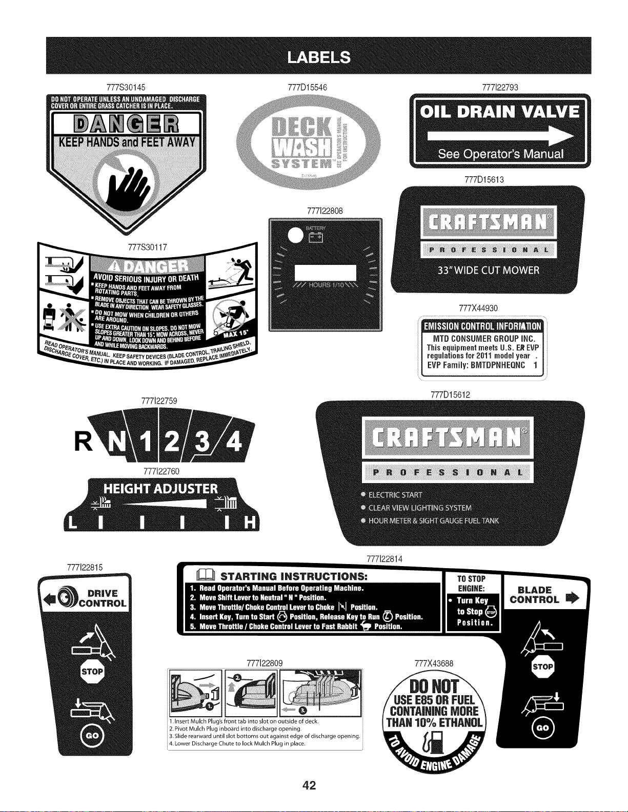
777S30145 777D15546 777122793
777D15613
777122808
777S30117
777122759
777122760
777X44930
MTDCONSUMERGROUPINC.
ThiseqaipmeatmeetsU.S. EREVP
I regulationsfor 2011 model year .
| EVP Family:BIVlTDPNHEQNCI
777D15612
777122815
777122814
777122809
1. insert Mulch Plug's front tab into slot on outside of deck.
2. Pivot Mulch Plug inboard into discharge opening,
3. Slide rearward until slot bottoms out against edge of discharge opening.
4. Lower Discharge Chute to lock Mulch Plug in place.
777X43688
42

43
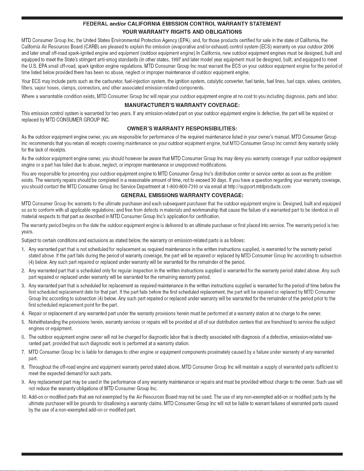
FEDERAL and/or CALIFORNIA EMISSION CONTROL WARRANTY STATEMENT
YOUR WARRANTY RIGHTS AND OBLIGATIONS
MTDConsumerGroupInc,the UnitedStatesEnvironmentalProtectionAgency (EPA),and, forthose productscertifiedfor sale in the stateof California,the
CaliforniaAir ResourcesBoard(CARB)are pleasedto explainthe emission(evaporativeand/or exhaust)controlsystem(ECS) warrantyon youroutdoor 2006
andlater smalloff-roadspark-ignitedengine andequipment(outdoorequipmentengine)In California,new outdoorequipmentengines mustbe designed,built and
equippedto meetthe State'sstringentanti-smogstandards(in otherstates, 1997andlater modelyear equipmentmustbe designed,built, and equippedto meet
theU.S. EPAsmalloff-road, sparkignitionengineregulations.MTDConsumerGroupInc mustwarrantthe ECSon your outdoorequipmentenginefor the periodof
timelisted belowprovidedtherehas been no abuse, neglector impropermaintenanceof outdoorequipmentengine.
Your ECSmay includeparts such as the carburetor,fuel-injectionsystem,the ignitionsystem,catalyticconverter,fuel tanks,fuel lines,fuel caps,valves,canisters,
filters,vapor hoses,clamps,connectors,andotherassociatedemission-relatedcomponents.
Wherea warrantableconditionexists, MTDConsumerGroupIncwill repairyouroutdoor equipmentengine at no cost to youincludingdiagnosis,parts and labor.
MANUFACTURER'S WARRANTY COVERAGE:
Thisemissioncontrolsystemis warrantedfor two years. If any emission-relatedpart on your outdoorequipmentengine is defective,the part will berepairedor
replacedby MTDCONSUMERGROUPINC.
OWNER'S WARRANTY RESPONSIBILITIES:
Asthe outdoorequipmentengineowner,you are responsiblefor performanceof the requiredmaintenancelisted inyour owner'smanual.MTDConsumerGroup
Inc recommendsthat you retain all receiptscoveringmaintenanceonyouroutdoor equipmentengine,but MTDConsumerGroupInc cannotdeny warrantysolely
forthe lackof receipts.
Asthe outdoorequipmentengineowner,you shouldhoweverbe awarethat MTDConsumerGroupInc maydenyyou warrantycoverageif your outdoorequipment
engineor a part has faileddue to abuse,neglect,or impropermaintenanceor unapprovedmodifications.
Youare responsiblefor presentingyouroutdoor equipmentengineto MTDConsumerGroupInc'sdistributioncenteror servicecenteras soon asthe problem
exists.The warrantyrepairsshouldbe completedin a reasonableamountof time, notto exceed30 days.If you havea questionregardingyour warrantycoverage,
you shouldcontactthe MTDConsumerGroupIncService Departmentat 1-800-800-7310orvia emailat http://support.mtdproducts.com
GENERAL EMISSIONS WARRANTY COVERAGE:
MTDConsumerGroupIncwarrantsto the ultimatepurchaserand eachsubsequentpurchaserthat theoutdoor equipmentengine is: Designed,built and equipped
so asto conformwithall applicableregulations;and freefromdefects in materialsand workmanshipthatcausethe failureof a warrantedpart to be identicalin all
materialrespectsto that part as describedin MTDConsumerGroup Inc'sapplicationfor certification.
The warrantyperiodbeginson the date theoutdoorequipmentengineis deliveredto an ultimatepurchaserorfirst placedinto service.The warrantyperiodis two
years.
Subjectto certain conditionsand exclusionsasstated below,the warrantyon emission-relatedparts is asfollows:
1. Any warrantedpart that is notscheduledfor replacementas requiredmaintenancein the written instructionssupplied, is warrantedforthe warrantyperiod
statedabove. Ifthe part fails duringthe periodof warrantycoverage,the part will be repairedor replacedbyMTDConsumerGroupInc accordingto subsection
(4) below. Anysuchpart repairedor replacedunderwarrantywillbe warrantedfor the remainderof the period.
2. Any warrantedpart that is scheduledonly for regularinspectionin the writteninstructionssupplied is warrantedforthe warrantyperiodstatedabove.Any such
part repairedor replacedunderwarrantywill be warrantedforthe remainingwarrantyperiod.
3. Any warrantedpart that is scheduledfor replacementas requiredmaintenancein the written instructionssuppliedis warrantedfor the periodof timebeforethe
first scheduledreplacementdatefor that part. If the partfails beforethefirst scheduledreplacement,the part will be repairedor replacedby MTDConsumer
GroupInc accordingto subsection(4) below.Any such part repairedor replacedunderwarrantywill bewarrantedfor the remainderof the periodprior to the
first scheduledreplacementpointfor the part.
4. Repairor replacementof any warrantedpart underthe warrantyprovisionshereinmustbe performedat a warrantystationat no chargeto the owner.
5. Notwithstandingthe provisionsherein,warrantyservicesor repairswill be providedat allof our distributioncentersthatare franchisedto servicethe subject
enginesor equipment.
6. The outdoorequipmentengine ownerwill not be chargedfor diagnostic laborthat is directlyassociatedwith diagnosisof a defective,emission-relatedwar-
rantedpart, providedthat suchdiagnosticwork is performedat a warrantystation.
7. MTDConsumerGroupInc is liablefor damagesto otherengine or equipmentcomponentsproximatelycausedby a failure underwarrantyof any warranted
part.
8. Throughoutthe off-roadengineand equipmentwarrantyperiodstatedabove,MTDConsumerGroupInc will maintaina supplyof warrantedparts sufficientto
meetthe expecteddemandfor such parts.
9. Any replacementpart maybe usedinthe performanceof any warrantymaintenanceor repairsand mustbe providedwithoutchargeto the owner.Suchuse will
notreducethe warrantyobligationsof MTDConsumerGroupInc.
10.Add-onor modifiedpartsthat are not exemptedbythe Air ResourcesBoardmaynot beused.The useof any non-exemptedadd-onor modifiedparts by the
ultimatepurchaserwill be groundsfor disallowinga warrantyclaims.MTDConsumerGroup Incwill not be liable to warrantfailuresof warrantedparts caused
bythe use of a non-exemptedadd-onor modifiedpart.

WARRANTED PARTS:
The repairor replacementof any warrantedpart otherwiseeligiblefor warrantycoveragemaybe excludedfromsuch warrantycoverageif MTDConsumerGroup
Inc demonstratesthatthe outdoor equipmentengine has beenabused,neglected,or improperlymaintained,and that suchabuse,neglect,or impropermainte-
nancewasthe direct causeof the needfor repairor replacementof the part.That notwithstanding,any adjustmentof a componentthat hasa factoryinstalled,
andproperlyoperating,adjustmentlimitingdevice is still eligiblefor warrantycoverage.Further,the coverageunderthis warrantyextendsonly to partsthat were
presentonthe off-roadengineand equipmentpurchased.
Thefollowing emissionwarrantypartsare covered(if applicable):
(1) FuelMeteringSystem
• Cold start enrichmentsystem(softchoke)
• Carburetorand internalparts (or fuel injectionsystem)
• Fuelpump
• Fueltank
(2) Air InductionSystem
• Air cleaner
• Intakemanifold
(3) IgnitionSystem
• Spark plug(s)
• Magneto ignitionsystem
(4) ExhaustSystem
• Catalyticconverter
• SAI (Reed valve)
(5) MiscellaneousItemsUsedin AboveSystem
• Vacuum,temperature,position,timesensitivevalvesand switches
• Connectorsandassemblies
(6) EvaporativeControl
• Fuelhose
• Fuelhoseclamps
• Tetheredfuel cap
• Carboncanister
• Vapor lines
GDOC-100223Rev.A
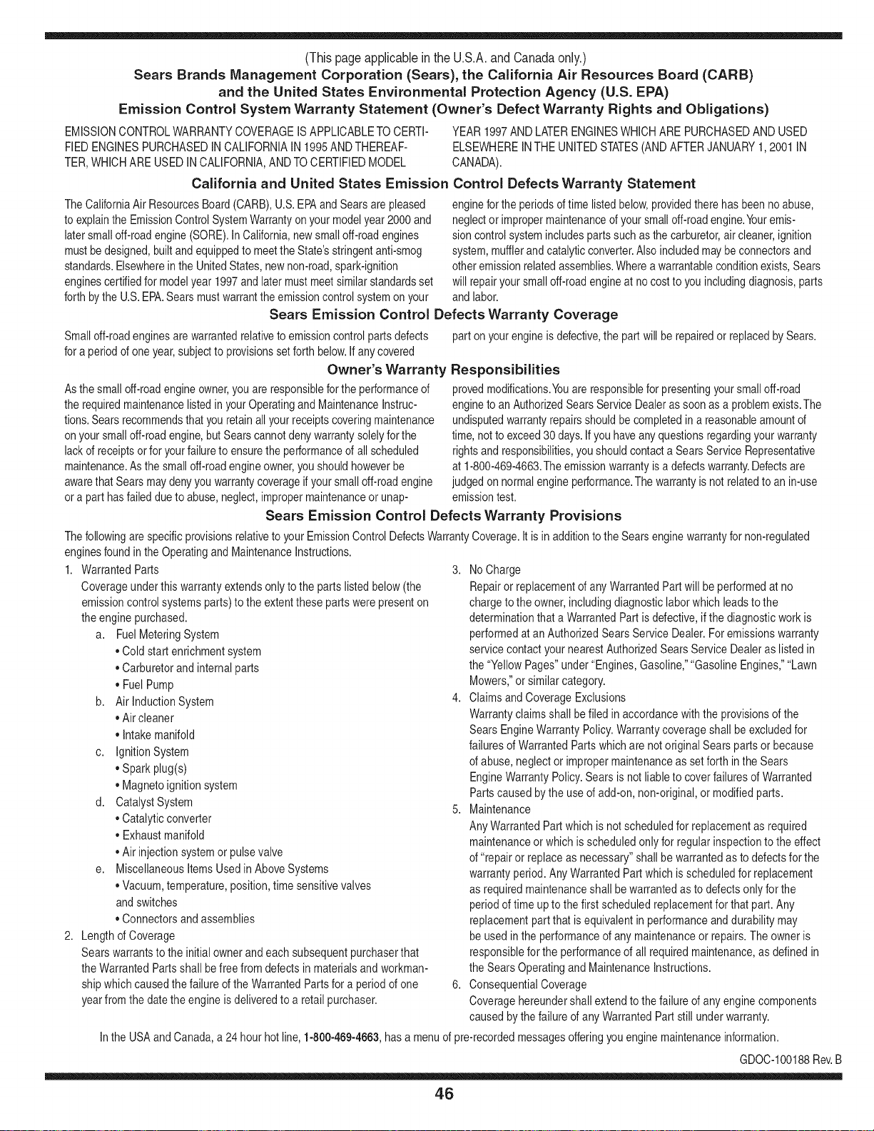
(Thispageapplicablein the U.S.A.and Canadaonly.)
Sears Brands Management Corporation (Sears), the California Air Resources Board (CARD)
and the United States Environmental Protection Agency (U.S. EPA)
Emission Control System Warranty Statement (Owner's Defect Warranty Rights and Obligations)
EMISSIONCONTROLWARRANTYCOVERAGEISAPPLICABLETOCERTI-
FIEDENGINESPURCHASEDINCALIFORNIAIN 1995ANDTHEREAF-
TER,WHICHARE USED INCALIFORNIA,ANDTOCERTIFIEDMODEL
California and United States Emission
The CaliforniaAir ResourcesBoard(CARD),U.S.EPAand Searsare pleased
to explainthe EmissionControlSystemWarrantyonyour modelyear2000and
latersmalloff-roadengine(SORE).InCalifornia,newsmall off-roadengines
mustbe designed,builtand equippedto meettheState'sstringentanti-smog
standards.Elsewherein the UnitedStates, newnon-road,spark-ignition
enginescertifiedfor modelyear 1997and latermustmeetsimilarstandardsset
forth bythe U.S.EPA.Sears mustwarranttheemissioncontrol systemonyour
YEAR 1997AND LATERENGINESWHICHARE PURCHASEDANDUSED
ELSEWHEREINTHE UNITEDSTATES(ANDAFTERJANUARY1,2001 IN
CANADA).
Control Defects Warranty Statement
enginefor the periodsoftime listedbelow,providedtherehas been noabuse,
neglector impropermaintenanceof your smalloff-roadengine.Youremis-
sion controlsystemincludespartssuch as thecarburetor,air cleaner,ignition
system,mufflerand catalyticconverter.Also includedmay be connectorsand
otheremissionrelatedassemblies.Wherea warrantableconditionexists,Sears
will repairyour smalloff-roadengineat nocostto you includingdiagnosis,parts
and labor.
Sears Emission Control Defects Warranty Coverage
Smalloff-roadenginesarewarrantedrelativeto emissioncontrol partsdefects
fora period of one year,subjectto provisionsset forthbelow.Ifany covered
Owner's Warranty
Asthe smalloff-roadengine owner,you are responsiblefor the performanceof
therequiredmaintenancelistedin yourOperatingand MaintenanceInstruc-
tions.Searsrecommendsthatyou retain all yourreceiptscoveringmaintenance
on yoursmalloff-roadengine,but Sears cannotdenywarrantysolelyfor the
lackof receiptsorfor yourfailureto ensurethe performanceof all scheduled
maintenance.As the smalloff-roadengineowner,you shouldhoweverbe
awarethat Searsmay denyyou warrantycoverageif your smalloff-roadengine
ora part hasfaileddueto abuse,neglect,impropermaintenanceor unap-
parton yourengineis defective,the part willbe repairedor replacedbySears.
Responsibilities
provedmodifications.Youare responsiblefor presentingyour smalloff-road
engineto an AuthorizedSearsServiceDealeras soonas a problemexists.The
undisputedwarrantyrepairsshouldbe completedina reasonableamountof
time,not to exceed30days. Ifyou haveany questionsregardingyourwarranty
rightsand responsibilities,you shouldcontacta SearsService Representative
at 1-800-469-4663.The emissionwarrantyis a defectswarranty.Defectsare
judgedon normalengineperformance.The warrantyis notrelatedto an in-use
emissiontest.
Sears Emission Control Defects Warranty Provisions
ThefollowingarespecificprovisionsrelativetoyourEmissionControlDefectsWarrantyCoverage.Itisin additiontotheSearsenginewarrantyfornon-regulated
enginesfoundin theOperatingand MaintenanceInstructions.
1. WarrantedParts
Coverageunderthis warrantyextendsonly to the parts listedbelow (the
emissioncontrolsystemsparts)to the extentthese partswere presenton
theengine purchased.
a. FuelMeteringSystem
• Cold start enrichmentsystem
• Carburetorand internalparts
• FuelPump
b. Air lnductionSystem
• Air cleaner
• Intakemanifold
c. IgnitionSystem
• Spark plug(s)
• Magnetoignitionsystem
d. CatalystSystem
• Catalyticconverter
• Exhaustmanifold
• Air injectionsystemor pulsevalve
e. MiscellaneousItemsUsedin AboveSystems
• Vacuum,temperature,position,timesensitivevalves
andswitches
• Connectorsandassemblies
2. Lengthof Coverage
Searswarrantsto the initialownerand eachsubsequentpurchaserthat
theWarrantedPartsshallbe free fromdefects in materialsandworkman-
shipwhich causedthe failure of the WarrantedPartsfor a periodof one
yearfromthe datethe engineis deliveredto a retailpurchaser.
3. NoCharge
Repairor replacementof anyWarrantedPartwill be performedat no
chargeto the owner,includingdiagnosticlabor whichleads to the
determinationthata WarrantedPartis defective,if the diagnosticwork is
performedat an AuthorizedSearsServiceDealer.For emissionswarranty
servicecontact yournearestAuthorizedSears ServiceDealeras listed in
the "YellowPages"under"Engines,Gasoline,""GasolineEngines,""Lawn
Mowers,"orsimilarcategory.
4. Claimsand CoverageExclusions
Warrantyclaimsshall be filed in accordancewiththe provisionsof the
Sears EngineWarrantyPolicy.Warrantycoverageshall be excludedfor
failuresof WarrantedPartswhichare not original Sears partsor because
of abuse,neglector impropermaintenanceas setforth inthe Sears
EngineWarrantyPolicy.Sears is notliableto coverfailuresof Warranted
Partscausedby the use of add-on,non-original,or modifiedparts.
5. Maintenance
Any WarrantedPart whichis notscheduledfor replacementas required
maintenanceor whichis scheduledonly for regularinspectionto the effect
of "repairor replaceas necessary"shallbe warrantedas to defectsfor the
warrantyperiod.Any WarrantedPartwhich is scheduledfor replacement
as requiredmaintenanceshallbe warrantedas to defectsonly forthe
periodof time upto the first scheduledreplacementfor that part. Any
replacementpart that is equivalentin performanceand durabilitymay
be usedin the performanceof any maintenanceor repairs.The owneris
responsibleforthe performanceof all requiredmaintenance,as definedin
the SearsOperatingand MaintenanceInstructions.
6. ConsequentialCoverage
Coveragehereundershallextendto thefailure of any enginecomponents
caused bythe failureof any WarrantedPartstill underwarranty.
Inthe USAandCanada,a 24 hour hot line, 1-800-469-4663,hasa menu of pre-recordedmessagesofferingyou enginemaintenanceinformation.
GDOC-100188Rev.B
46
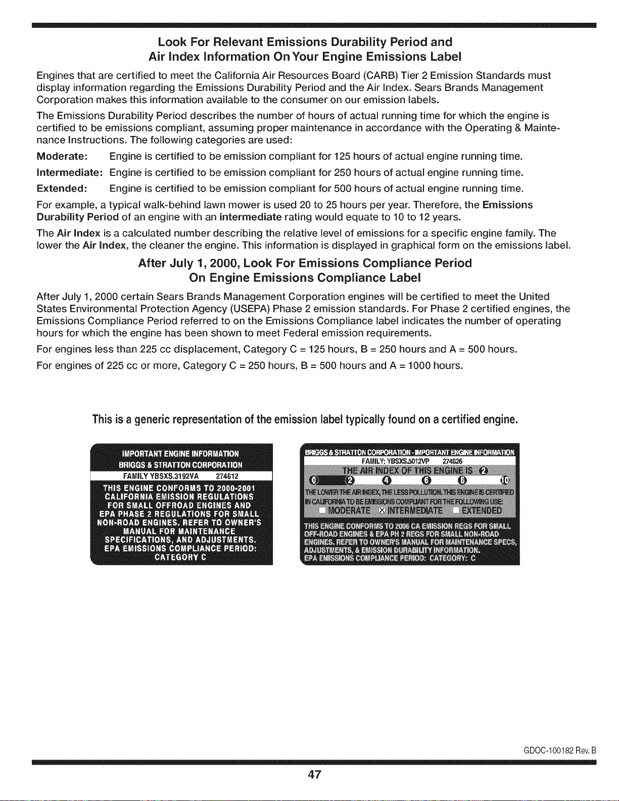
Look For Relevant Emissions Durability Period and
Air index information On Your Engine Emissions Label
Engines that are certified to meet the California Air Resources Board (CARB) Tier 2 Emission Standards must
display information regarding the Emissions Durability Period and the Air Index. Sears Brands Management
Corporation makes this information available to the consumer on our emission labels.
The Emissions Durability Period describes the number of hours of actual running time for which the engine is
certified to be emissions compliant, assuming proper maintenance in accordance with the Operating & Mainte-
nance Instructions. The following categories are used:
Moderate: Engine is certified to be emission compliant for 125 hours of actual engine running time.
Intermediate: Engine is certified to be emission compliant for 250 hours of actual engine running time.
Extended: Engine is certified to be emission compliant for 500 hours of actual engine running time.
For example, a typical walk-behind lawn mower is used 20 to 25 hours per year. Therefore, the Emissions
Durability Period of an engine with an intermediate rating would equate to 10 to 12 years.
The Air index is a calculated number describing the relative level of emissions for a specific engine family. The
lower the Air Index, the cleaner the engine. This information is displayed in graphical form on the emissions label.
After July 1,2000, Look For Emissions Compliance Period
On Engine Emissions Compliance Label
After July 1, 2000 certain Sears Brands Management Corporation engines will be certified to meet the United
States Environmental Protection Agency (USEPA) Phase 2 emission standards. For Phase 2 certified engines, the
Emissions Compliance Period referred to on the Emissions Compliance label indicates the number of operating
hours for which the engine has been shown to meet Federal emission requirements.
For engines less than 225 cc displacement, Category C = 125 hours, B = 250 hours and A = 500 hours.
For engines of 225 cc or more, Category C = 250 hours, B = 500 hours and A = 1000 hours.
This is a generic representation of the emission label typically found on a certified engine.
FAMILYYBSXS.3192VA 274812
GDOC-100182Rev.B
47

Congratulations on making a smart purchase. Your new Craftsman® product is designed and
manufactured for years of dependable operation. But like all products, it may require repair
from time to time. That's when having a Repair Protection Agreement can save you money and
aggravation.
Here's what the Repair Protection Agreement* includes:
[] Expert service by our 10,000 professional repair specialists
[] Unlimited service and no charge for parts and labor on all covered repairs
[] Product replacement up to $1500 if your covered product can't be fixed
[] Discount of 25% from regular price of service and related installed parts not covered by the
agreement; also, 25% off regular price of preventive maintenance check
[] Fast help by phone - we call it Rapid Resolution - phone support from a Sears representative.
Think of us as a "talking owner's manual."
Once you purchase the Repair Protection Agreement, a simple phone call is all that it takes for you
to schedule service. You can call anytime day or night, or schedule a service appointment online.
The Repair Protection Agreement is a risk-free purchase. If you cancel for any reason during the
product warranty period, we will provide a full refund. Or, a prorated refund anytime after the
product warranty period expires. Purchase your Repair Protection Agreement today!
Some limitations and exclusions apply. For prices and additional information in the U.S.A.
call 1=800=827=6655.
*Coverage in Canada varies on some items. For full details call Sears Canada at 1=800=361=
6665.
Sears Installation Service
For Sears professional installation of home appliances, garage door openers, water heaters, and
other major home items, in the U.S.A. or Canada call 1=800=4=MY=HOME®.
48
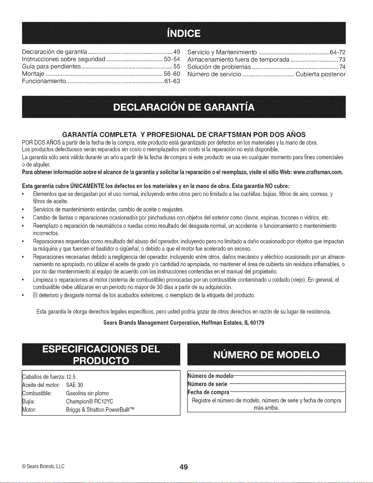
Declaraci6n de garantia .................................................. 49
Instrucciones sobre seguridad ................................. 50-54
Guia para pendientes ...................................................... 55
Montaje ..................................................................... 56-60
Funcionamiento .......................................................... 61-63
Servicio y Mantenimiento .......................................... 64-72
Almacenamiento fuera de temporada ............................ 73
Soluci6n de problemas ................................................... 74
NOmero de servicio ............................... Cubierta posterior
GARANTiA COMPLETA Y PROFESIONAL DE CRAFTSMAN POR DOS AMOS
PORDOSAMOSapartir dela fechade lacompra,esteproductoest_garantizadopor defectosen losmaterialesy la manode obra.
Los productosdefectuososser_nreparadossin costoo reemplazadossin costosi la reparaci6nnoest_disponible.
Lagaranfias61oser_v_lidaduranteuna_oa partirde lafechadecomprasi este productose usaen cualquiermomentopara fines comerciales
ode alquiler.
Paraobtener informaci6nsobreel alcancede la garantiay solicitarla reparaci6no el reemplazo,visiteel sitioWeb:www.craftsman.com.
Esta garantia cubreONICAMENTElos defectos en losmateriales yen la mano de obra. Estagarantia NOcubre:
• Elementosquese desgastanpor el usonormal,incluyendoentreotrospero no limitadoalas cuchillas,bujias,filtrosde aire,correas,y
filtrosdeaceite.
• Serviciosde mantenimientoest_ndar,cambiode aceiteo reajustes.
• Cambiode Ilantaso reparacionesocasionadosporpinchadurasconobjetosdel exteriorcomo clavos,espinas,toconeso vidrios,etc.
• Reemplazoo reparaci6nde neum_ticoso ruedascomoresultadodel desgastenormal,unaccidente,o funcionamientoo mantenimiento
incorrectos.
• Reparacionesrequeridascomoresultadodel abusodeloperador,incluyendopero no limitadoa da_oocasionadopor objetosque impactan
la m_quinay quetuercenel bastidoro cig(Je_al,o debidoa que el motorfue aceleradoen exceso.
• Reparacionesnecesariasdebidoa negligenciadel operador,incluyendoentre otros,da_osmec_nicoy el_ctricoocasionadoporun almace-
namientonoapropiado,no utilizarel aceitede gradoy/o cantidadno apropiada,no mantenerel _reade cubiertasin residuosinflamables,o
porno dar mantenimientoal equipodeacuerdocon las instruccionescontenidasen el manualdel propietario.
• Limpiezao reparacionesal motor(sistemadecombustible)provocadasporun combustiblecontaminadou oxidado(viejo).En general,el
combustibledebeutilizarseen unperiodono mayorde 30 dias a partirde su adquisici6n.
• Eldeterioroy desgastenormalde losacabadosexteriores,o reemplazode la etiquetadel producto.
Estagarantialeotorgaderechoslegalesespecificos,pero ustedpodria gozarde otros derechosen raz6nde su lugarde residencia.
Sears Brands Management Corporation, Hoffman Estates, IL 60179
Caballosde fuerza:12.5
Aceitedel motor: SAE30
Combustible: Gasolinasin plomo
Bujia: Champion®RC12YC
Motor: Briggs& StrattonPowerBuiltTM
N_merode modelo-
N_merode serie --
Fechade compra-
RegistreelnQmerode modelo,nQmerode seriey fechade compra
m_sarrba.
© SearsBrands,LLC 49
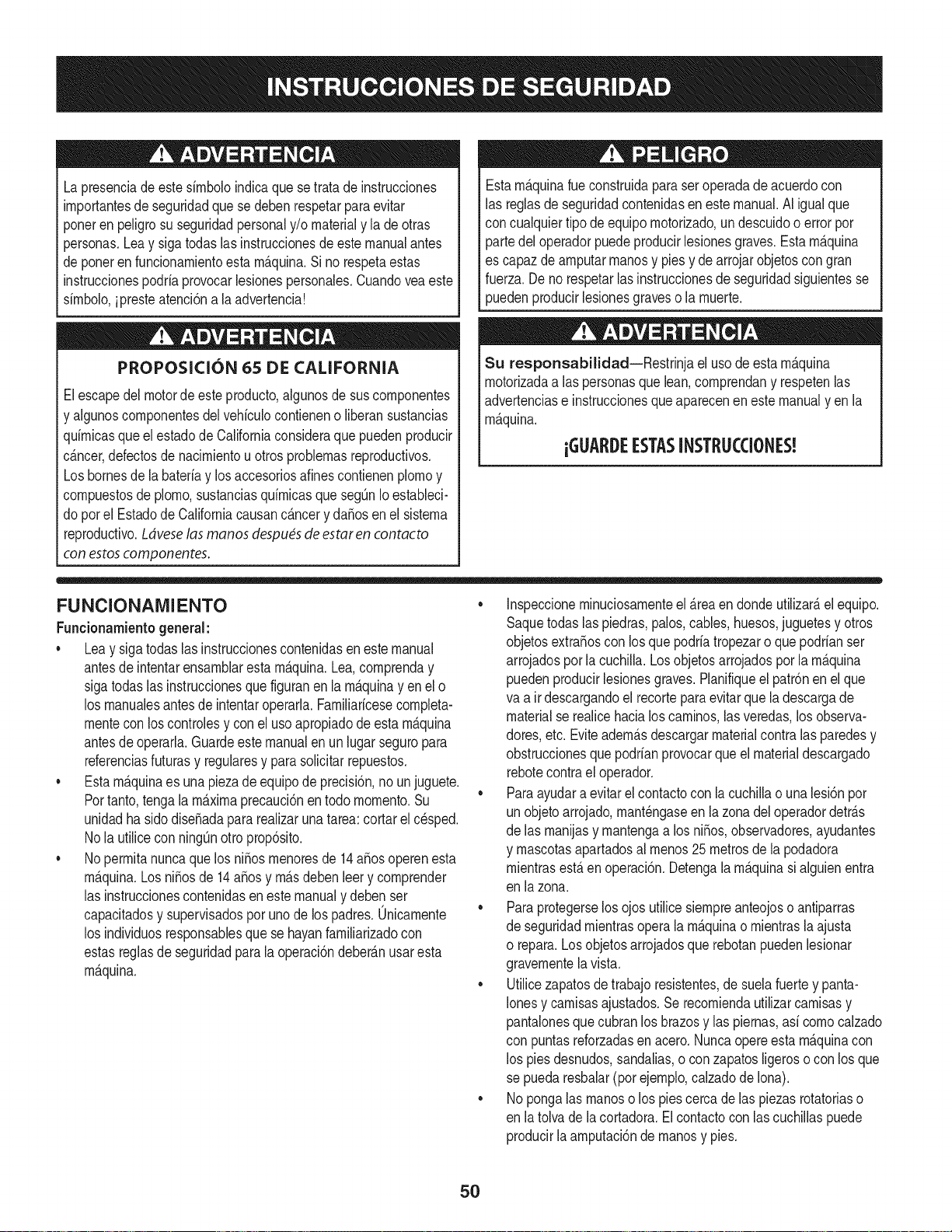
Lapresenciade este sirnboloindicaque setrata de instrucciones
irnportantesde seguridadquese deben respetarpara evitar
ponerenpeligrosu seguridadpersonaly/o materialy la de otras
personas.Leay sigatodas lasinstruccionesde este manualantes
de poneren funcionarnientoesta rn_.quina.Si no respetaestas
instruccionespodriaprovocarlesionespersonales.Cuandoveaeste
sirnbolo,ipresteatenci6na la advertencia!
PROPOSICION 65 DE CALIFORNIA
Elescapedel motorde este producto,algunosde suscornponentes
y algunoscornponentesdel vehiculocontieneno liberansustancias
quirnicasqueel estadode Californiaconsideraque puedenproducir
c_.ncer,defectosde nacirnientouotrosproblernasreproductivos.
Losbornesdela bateriay losaccesoriosdines contienenplornoy
cornpuestosde plorno,sustanciasquirnicasquesegOnIoestableci-
do pot el EstadodeCaliforniacausanc_.ncery da_osen el sisterna
reproductivo.Ldveselas manos despu_sde estaren contacto
con estoscomponentes.
Estarn_.quinarueconstruidapara seroperadade acuerdocon
las reglasde seguridadcontenidaseneste manual.AI igualque
concualquiertipo deequipornotorizado,un descuidoo error por
partedeloperadorpuedeproducirlesionesgraves.Estarn_.quina
es capazde arnputarrnanosy piesy dearrojarobjetoscon gran
fuerza.De norespetarlas instruccionesde seguridadsiguientesse
puedenproducirlesionesgraveso la rnuerte.
Su responsabilidad--Restrinja el usode esta rn_.quina
rnotorizadaalas personasque lean,cornprendany respetenlas
advertenciase instruccionesqueaparecenenestemanualyen la
rn_.quina.
iGUARI)E ESTASINSTRUCCIONES!
FUNCIONAMIENTO
Funcionarnientogeneral:
• Leay siga todaslas instruccionescontenidasen este manual
antesde intentarensarnblaresta rn_.quina.Lea,cornprenday
sigatodaslas instruccionesque figuranen la rn_.quinayen el o
los rnanualesantesde intentaroperarla.Farniliaricesecornpleta-
rnentecon loscontrolesy conel uso apropiadodeestarn_.quina
antesde operarla.Guardeeste manualen un lugarseguropara
referenciasfuturasy regulatesy parasolicitarrepuestos.
• Estarn_.quinaes una piezade equipode precisi6n,no un juguete.
Portanto,tengala maximaprecauci6nen todornornento.Su
unidadha sidodise_adapara realizaruna tarea:cortar el c_sped.
No la utilicecon ningOnottoprop6sito.
• No perrnitanuncaque losni_os rnenoresde 14a_osoperenesta
rn_.quina.Los ni_osde 14a_osy rn_.sdebenleery cornprender
las instruccionescontenidasenestemanualy debenser
capacitadosy supervisadospor unode los padres.Onicarnente
los individuosresponsablesque se hayanfarniliarizadocon
estasreglasdeseguridadparala operaci6ndeber_.nusaresta
rn_.quina.
• Inspeccionerninuciosarnenteel _.reaendondeutilizar_,el equipo.
Saquetodaslas piedras,palos,cables,huesos,juguetesy otros
objetosextra_oscon los quepodriatropezaro que podrianser
arrojadosporla cuchilla.Losobjetosarrojadosporla rn_.quina
puedenproducirlesionesgraves.Planifiqueel patr6nen el que
va a ir descargandoel recorteparaevitarquela descargade
materialse realicehacialoscarninos,las veredas,losobserva-
dotes,etc. Eviteadern_.sdescargarmaterialcontralas paredesy
obstruccionesquepodrianprovocarque el materialdescargado
rebotecontrael operador.
• Paraayudara evitarel contactocon lacuchillao unalesi6npor
un objetoarrojado,rnant_ngaseen la zonadel operadordetr_.s
de las rnanijasy rnantengaa los ni_os,observadores,ayudantes
y rnascotasapartadosal rnenos25 metrosde la podadora
rnientrasest,.en operaci6n.Detengala rn_.quinasi alguienentra
en lazona.
• Paraprotegerselosojos utilicesiernpreanteojoso antiparras
de seguridadrnientrasoperala rn_.quinao rnientrasla ajusta
o repara.Losobjetosarrojadosquerebotanpuedenlesionar
gravernentelavista.
• Utilicezapatosde trabajoresistentes,de suelafuertey panta-
Ionesy carnisasajustados.Se recorniendautilizarcarnisasy
pantalonesquecubranlos brazosy las piernas,asi cornocalzado
con puntasreforzadasen acero.Nuncaopereesta rn_.quinacon
los pies desnudos,sandalias,o conzapatosligeroso con losque
se puedaresbalar(por ejernplo,calzadode Iona).
• Nopongalas rnanoso los piescerca de las piezasrotatoriaso
en latolva de la cortadora.El contactocon las cuchillaspuede
producirlaarnputaci6nde rnanosy pies.
5O
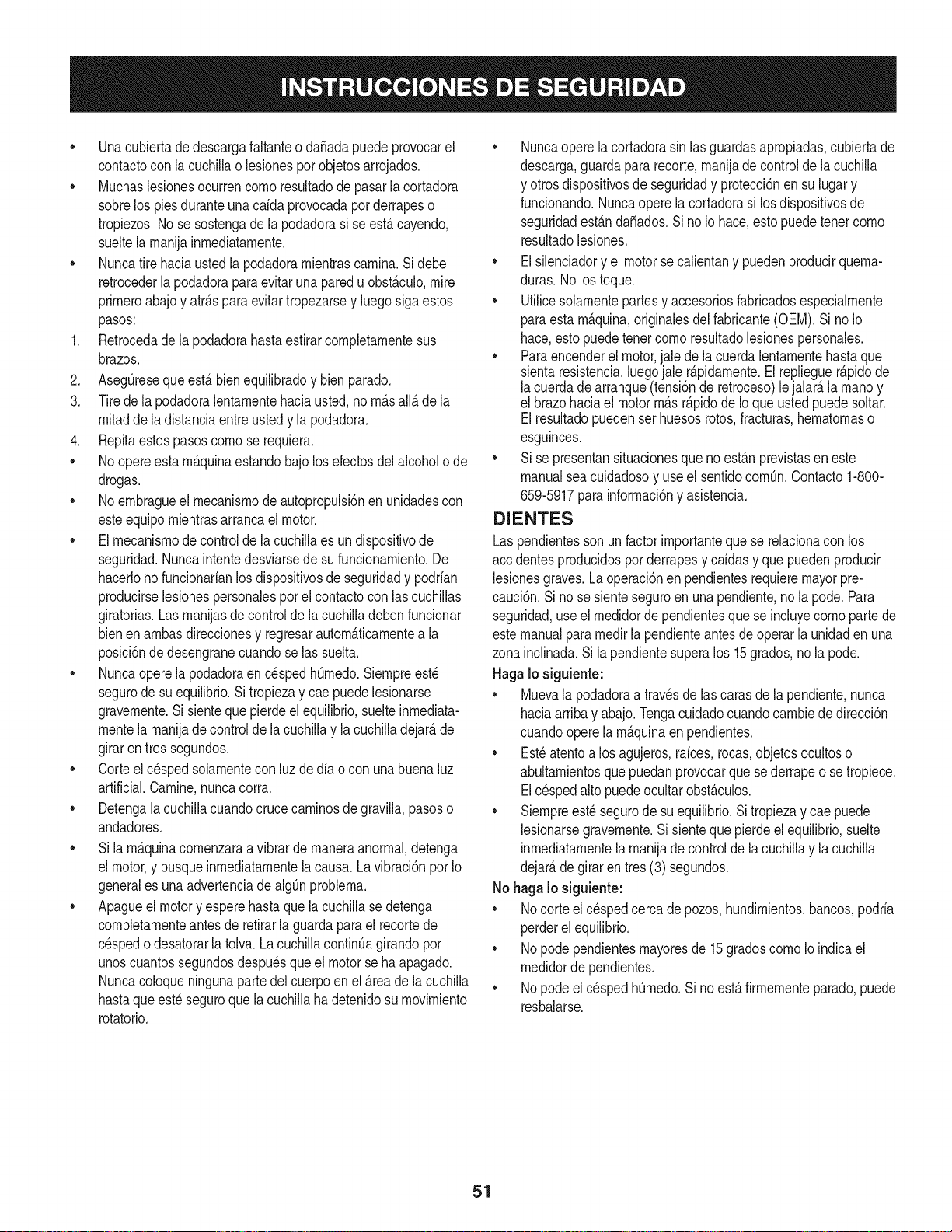
• Unacubiertade descargafaltanteo da_adapuede provocarel
contactocon la cuchillao lesionesporobjetosarrojados.
Muchaslesionesocurrencornoresultadode pasarla cortadora
sobrelos piesduranteunacaida provocadaporderrapeso
tropiezos.No se sostengade la podadorasi se est,.cayendo,
sueltela rnanijainmediatarnente.
Nuncatire haciaustedla podadorarnientrascarnina.Si debe
retrocederla podadoraparaevitaruna paredu obst_.culo,mire
prirneroabajoy atr_.sparaevitartropezarsey luegosigaestos
pasos:
1. Retrocedade la podadorahastaestirarcornpletarnentesus
brazos.
2. AsegOreseque est,. bienequilibradoy bienparado.
3. Tirede la podadoralentarnentehaciausted,no rn_.sall_.de la
rnitadde ladistanciaentreustedy lapodadora.
4. Repitaestospasoscornose requiera.
• No opereestarn_.quinaestandobajo losefectosdel alcoholo de
drogas.
• No ernbragueel mecanisrnode autopropulsi6nen unidadescon
esteequipornientrasarrancael motor.
• Elrnecanisrnodecontrolde la cuchillaes un dispositivode
seguridad.Nuncaintentedesviarsede su funcionarniento.De
hacerlono funcionarianlos dispositivosde seguridady podrian
producirselesionespersonalesporel contactocon lascuchillas
giratorias.Lasrnanijasdecontrolde la cuchilladeben funcionar
bienen arnbasdireccionesy regresarautorn_.ticarnentea la
posici6ndedesengranecuandose las suelta.
• Nuncaoperela podadoraen c_spedhOrnedo.Siernpreest_
segurode su equilibrio.Si tropiezay cae puedelesionarse
gravernente.Sisienteque pierdeel equilibrio,suelte inrnediata-
rnentela rnanijade controlde la cuchillay la cuchilladejar_,de
girarentres segundos.
• Corteel cespedsolarnentecon luz dedia o con unabuenaluz
artificial.Carnine,nuncacorra.
• Detengala cuchillacuandocruce carninosde gravilla,pasoso
andadores.
• Si larn_.quinacornenzaraa vibrarde rnaneraanorrnal,detenga
el motor,y busqueinrnediatarnentelacausa.Lavibraci6npor Io
generales unaadvertenciade algQnproblerna.
• Apagueelmotor y esperehastaque la cuchillase detenga
cornpletarnenteantesde retirarla guardapara el recortede
cespedo desatorarla tolva. La cuchillacontinOagirando por
unoscuantossegundosdespu_squeel motorse ha apagado.
Nuncacoloqueningunapartedel cuerpoen el _.reade la cuchilla
hastaqueest_ seguroque la cuchilla ha detenidosu rnovirniento
rotatorio.
Nuncaoperela cortadorasin las guardasapropiadas,cubiertade
descarga,guardapararecorte,rnanijade control de la cuchilla
y otrosdispositivosde seguridady protecci6nen su lugary
funcionando.Nuncaopere la cortadorasi los dispositivosde
seguridadest_.nda_ados.Si no Io hace,esto puedetenet corno
resultadolesiones.
• Elsilenciadory el motorse calientany puedenproducirquerna-
duras.Nolos toque.
• Utilicesolarnentepartesy accesoriosfabricadosespecialrnente
paraestarn_.quina,originalesdel fabricante(OEM). Si no Io
hace,estopuedetenercornoresultadolesionespersonales.
• Paraencenderel motor,jale dela cuerdalentarnentehastaque
sientaresistencia,luegojale r@idarnente.Elreplieguer@idode
lacuerdadearranque(tensi6nde retroceso)le jalar_,la rnanoy
el brazohaciael motorrn_.sr@idode Ioque ustedpuedesoltar.
Elresultadopuedenser huesosrotos,fracturas,hernatornaso
esguinces.
Sise presentansituacionesqueno est_.nprevistasen este
manualseacuidadosoy useel sentidocornQn.Contacto1-800-
659-5917parainforrnaci6ny asistencia.
DIENTES
Laspendientessonun factorirnportantequese relacionacon los
accidentesproducidosporderrapesy caidasy quepuedenpro@@
lesionesgraves.La operaci6nen pendientesrequieremayorpre-
cauci6n.Sino se sienteseguroen una pendiente,no la pode.Para
seguridad,use el rnedidordependientesquese incluyecornopartede
estemanualpararnedirla pendienteantes de operar la unidaden una
zonainclinada.Si la pendientesuperalos 15grados,no la pode.
HagaIo siguiente:
• Muevala podadoraa travesde las carasde la pendiente,nunca
haciaarribay abajo.Tengacuidadocuandocarnbiededirecci6n
cuandooperela rn_.quinaen pendientes.
• Est_atentoa los agujeros,raices,rocas,objetosocultoso
abultarnientosquepuedanprovocarque sederrapeo se tropiece.
Elc_spedalto puedeocultarobst_.culos.
Siernpreest_segurodesu equilibrio.Sitropiezay cae puede
lesionarsegravernente.Si sJentequepier@el equilibrio,suelte
inrnediatarnentelarnanijade controlde la cuchillay la cuchilla
dejar_,degirar en tres (3) segundos.
No hagaIo siguiente:
• I/o corteel cespedcercade pozos,hundirnientos,bancos,podria
perderel equilibrio.
• Nopodependientesrnayoresde 15gradoscornoIo indicael
rnedidorde pendientes.
• Nopodeel cespedhOrnedo.Si noest,.firrnernenteparado,puede
resbalarse.
51
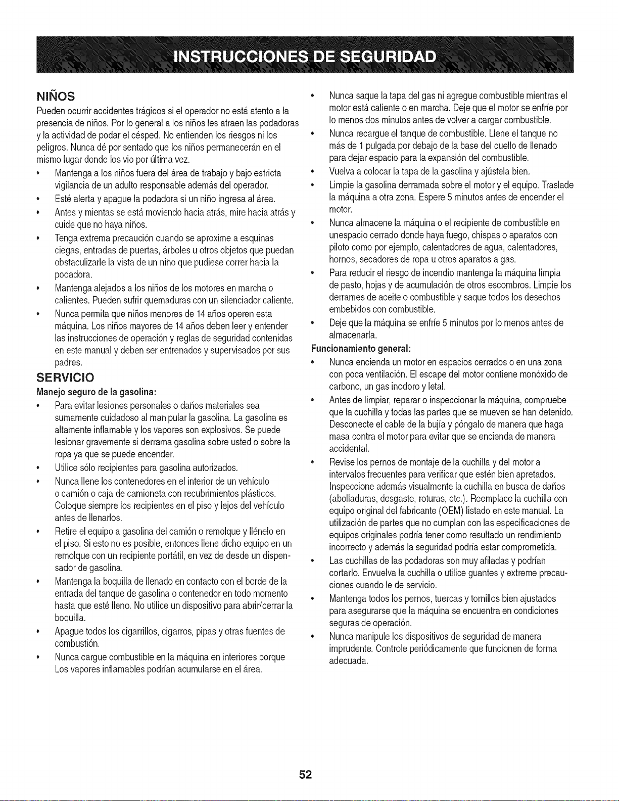
N QOS
Puedenocurriraccidentestr_.gicossi eloperadornoest,.atentoa la
presenciade ni_os.Por Iogenerala los ni_osles atraenlas podadoras
y la actividadde podarel c_sped.Noentiendenlos riesgosnilos
peligros.Nuncad_por sentadoque los ni_osperrnanecer_.nen el
rnisrnolugardondelosvio por Oltirnavez.
• Mantengaa los ni_osfuera delAreadetrabajoy bajo estricta
vigilanciade unadultoresponsableadern_.sdeloperador.
Est_alerta y apaguela podadorasi un ni_o ingresaal Area.
Antesy rnientasse est,.rnoviendohaciaatr_.s,mirehaciaatr_.sy
cuidequeno hayani_os.
Tengaextrernaprecauci6ncuandoseaproxirnea esquinas
ciegas,entradasdepuertas,_.rbolesu otrosobjetosque puedan
obstaculizarlelavista deun ni_oque pudiesecorrerhaciala
podadora.
Mantengaalejadosa los ni_osdelos rnotoresenrnarchao
calientes.Puedensufrirquernadurascon un silenciadorcaliente.
Nuncaperrnitaqueni_osrnenoresde 14a_osoperenesta
rn_.quina.Los ni_osrnayoresde 14a_osdebenleery entender
las instruccionesde operaci6ny reglasdeseguridadcontenidas
eneste manualy debenser entrenadosy supervisadospor sus
padres.
SERVIClO
Manejo segurode la gasolina:
• Paraevitarlesionespersonaleso daSosrnaterialessea
surnarnentecuidadosoal rnanipularlagasolina.Lagasolinaes
altarnenteinflarnabley losvaporesson explosivos.Sepuede
lesionargravernentesi derrarnagasolinasobreustedo sobrela
ropaya quese puedeencender.
• Utilices61orecipientesparagasolinaautorizados.
• NuncaIlenelos contenedoresenel interiordeunvehiculo
ocarni6nocaja decarnionetacon recubrirnientospl_.sticos.
Coloquesiernprelos recipientesenel pisoy lejosdelvehiculo
antesde Ilenarlos.
• Retireel equipoa gasolinadel carni6no rernolquey II_neloen
el piso.Si estono es posible,entoncesIlenedichoequipo en un
rernolquecon un recipienteport_.til,en vezdedesdeundispen-
sadordegasolina.
• Mantengala boquillade Ilenadoen contactocon el horde de la
entradadeltanquede gasolinao contenedoren todornornento
hastaqueest_ Ileno.No utilice un dispositivopara abrir/cerrarla
boquilla.
• Apaguetodoslos cigarrillos,cigarros,pipasy otrasfuentesde
cornbusti6n.
• Nuncacarguecombustibleen larn_.quinaen interioresporque
Losvaporesinflarnablespodrianacurnularseen el_.rea.
• Nuncasaquelatapadel gasni agreguecombustiblernientrasel
motorest,.calienteo en rnarcha.Dejeque el motorse enfriepor
Io rnenosdos rninutosantesde volvera cargarcombustible.
• Nuncarecargueel tanquedecombustible.Lleneel tanqueno
rn_.sde 1 pulgadapor debajodela basedel cuellode Ilenado
paradejar espacioparala expansi6ndel combustible.
• Vuelvaa colocarla tapade la gasolinay ajOstelabien.
• Lirnpiela gasolinaderrarnadasobreel motory el equipo.Traslade
la rn_.quinaa otrazona.Espere5 rninutosantesde encenderel
motor.
• Nuncaalrnacenela rn_.quinao el recipientede combustibleen
unespaciocerradodondehayafuego,chispaso aparatoscon
pilotocornoporejernplo,calentadoresde agua,calentadores,
hornos,secadoresde ropau otrosaparatosa gas.
• Parareducirel riesgode incendiornantengala rn_.quinalirnpia
de pasto,hojasy deacurnulaci6nde otrosescornbros.Lirnpielos
derrarnesde aceiteo combustibley saquetodos losdesechos
ernbebidoscon combustible.
• Dejeque la rn_.quinase enfrie5 rninutospor Iornenosantesde
alrnacenarla.
Funcionamientogenerah
• Nuncaenciendaunmotoren espacioscerradoso en unazona
con pocaventilaci6n.Elescapedel motorcontienernon6xidode
carbono,ungas inodoroy letal.
• Antesde lirnpiar,repararo inspeccionarla rn_.quina,cornpruebe
que lacuchillay todaslas partesquese rnuevense han detenido.
Desconecteel cablede la bujiay p6ngalode rnaneraque haga
rnasacontrael motorparaevitarque se enciendade rnanera
accidental.
• Reviselos pernosde rnontajede lacuchillay delmotora
intervalosfrecuentesparaverificarqueest_nbien apretados.
Inspeccioneadern_.svisualrnentela cuchillaenbuscade daSos
(abolladuras,desgaste,roturas,etc.).Reernplacela cuchillacon
equipooriginaldel fabricante(OEM)listadoen este manual.La
utilizaci6nde partesqueno curnplancon lasespecificacionesde
equiposoriginalespodriatenetcornoresultadoun rendirniento
incorrectoy adern_.sla seguridadpodriaestarcornprornetida.
• Lascuchillasde las podadorasson rnuyafiladasy podrian
cortarlo.Envuelvalacuchillao utilice guantesy extremeprecau-
clonescuandole de servicio.
• Mantengatodoslos pernos,tuercasy tornillosbienajustados
paraasegurarseque la rn_.quinaseencuentraen condiciones
segurasdeoperaci6n.
• Nuncarnanipulelosdispositivosde seguridaddernanera
irnprudente.Controleperi6dicarnentequefuncionendeforrna
adecuada.
52
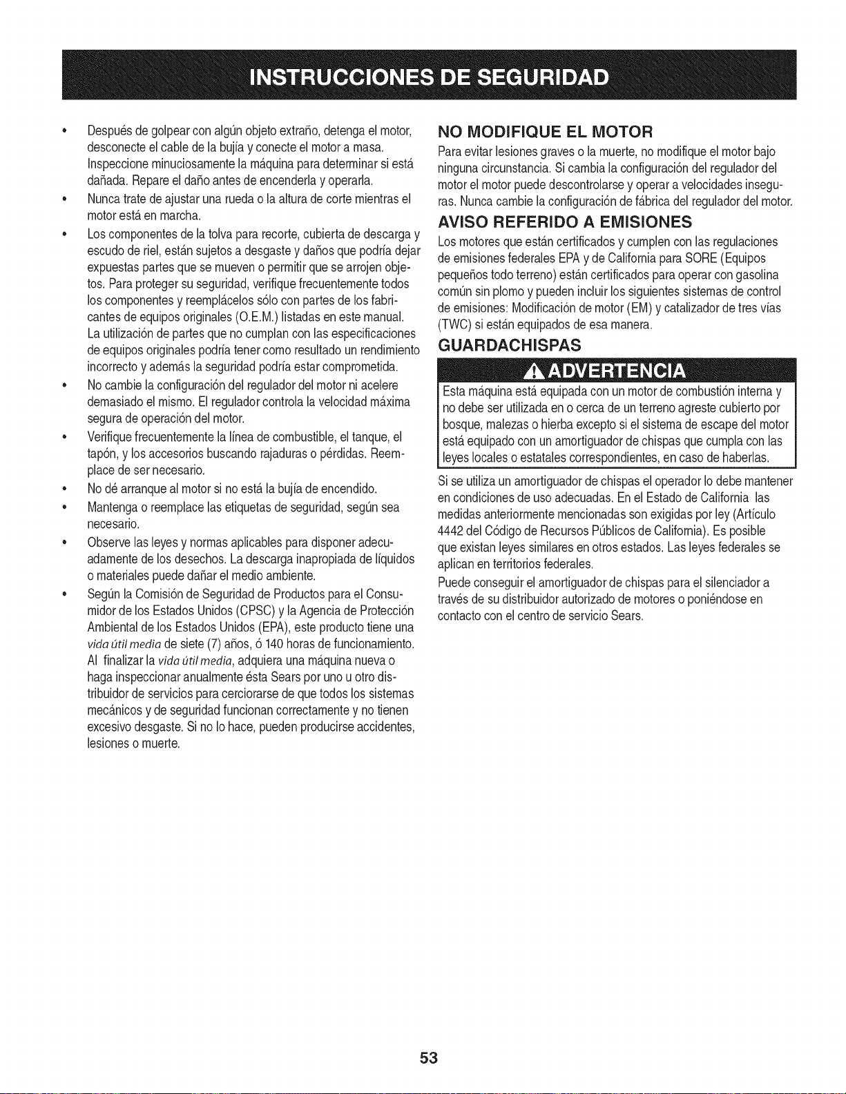
• Despu_sdegolpearcon algOnobjetoextrafio,detengael motor,
desconecteelcablede la bujfay conecteel motora rnasa.
Inspeccionerninuciosarnentela rn_.quinaparadeterrninarsi est,.
da_ada.Repareel da_o antesde encenderlay operarla.
• Nuncatratede ajustaruna ruedao la alturade corte rnientrasel
motorest,.en rnarcha.
• Loscornponentesde latolvapara recorte,cubiertade descargay
escudode riel,est_.nsujetosa desgastey da_osque podriadejar
expuestaspartesquese rnueveno perrnitirque se arrojenobje-
tos. Paraprotegersu seguridad,verifiquefrecuenternentetodos
los cornponentesy reernpl_.celoss61ocon partesde losfabri-
cantesde equiposoriginales(O.E.M.)listadasen este manual.
La utilizaci6nde partesque no curnplancon las especificaciones
deequiposoriginalespodriatenercornoresultadoun rendirniento
incorrectoy adern_.slaseguridadpodriaestarcomprornetida.
• No carnbielaconfiguraci6ndel reguladordel motorni acelere
dernasiadoelrnisrno.El reguladorcontrolala velocidadrn_.xirna
segurade operaci6ndel motor.
• Verifiquefrecuenternentela Ifneadecombustible,el tanque,el
tap6n,y losaccesoriosbuscandorajaduraso perdidas.Reern-
placedeset necesario.
• No d_arranqueal motorsi noest,.la bujfade encendido.
• Mantengao reernplacelasetiquetasde seguridad,segOnsea
necesario.
• Observelasleyesy norrnasaplicablesparadisponeradecu-
adarnentedelos desechos.La descargainapropiadade liquidos
o rnaterialespuededa_arel medicarnbiente.
• SegOnla Cornisi6nde Seguridadde Productosparael Consu-
rnidordelos EstadosUnidos(CPSC)y la Agenciade Protecci6n
Arnbientalde los EstadosUnidos(EPA),esteproductotiene una
vidadtil media desiete(7)a_os,6 140horasde funcionarniento.
AI finaiizar[adda dtilmedia, adquieraunarn_.quinanuevao
hagainspeccionaranualrnente_staSearsporunou otrodis-
tribuidorde serviciosparacerciorarsedeque todos los sisternas
rnec_.nicosy de seguridadfuncionancorrectarnentey no tienen
excesivodesgaste.Si no Io hace,puedenproducirseaccidentes,
lesionesornuerte.
NO MODIFIQUE EL MOTOR
Paraevitarlesionesgraveso la rnuerte,no rnodifiqueel motorbajo
ningunacircunstancia.Si carnbiala configuraci6ndel reguladordel
motorelmotor puededescontrolarsey operara velocidadesinsegu-
ras.Nuncacarnbielaconfiguraci6nde f_.bricadel reguladordel motor.
AVISO REFERIDO A EMISIONES
Losrnotoresqueest&ncertificadosy curnplencon las regulaciones
de ernisionesfederalesEPAy de CaliforniaparaSORE(Equipos
peque_ostodoterreno)est_.ncertificadosparaoperarcon gasolina
cornOnsinplornoy puedenincluirlossiguientessisternasde control
de ernisiones:Modificaci6ndemotor(EM) y catalizadorde tresvias
(TWO)si est_.nequipadosde esa rnanera.
GUARDACHISPAS
Estarn&quinaest,.equipadacon unmotorde cornbusti6ninternay
nodebe ser utilizadaen o cercade un terrenoagrestecubiertopor
bosque,rnalezaso hierbaexceptosi el sisternade escapedelmotor
est,.equipadocon un arnortiguadorde chispasque curnplaconlas
leyeslocaleso estatalescorrespondientes,en caso de haberlas.
Sise utilizaun arnortiguadordechispasel operadorIo debernantener
en condicionesde usoadecuadas.Enel Estadode California las
rnedidasanteriorrnenternencionadassonexigidasporley (Arficulo
4442del C6digode RecursosPOblicosde California).Es posible
queexistanleyessirnilaresen otros estados.Lasleyesfederalesse
aplicanenterritoriosfederales.
Puedeconseguirelarnortiguadorde chispasparael silenciadora
travesde sudistribuidorautorizadode rnotoreso poni_ndoseen
contactocon elcentrode servicioSears.
53
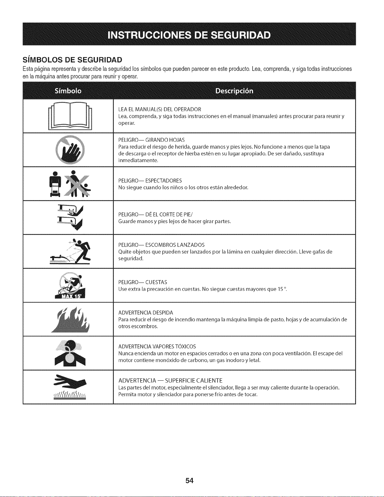
SilVIBOLOS DE SEGURIDAD
Estap&ginarepresentay describelaseguridadlos simbolosque puedenpareceren este producto.Lea,comprenda,y sigatodas instrucciones
en lam_quinaantesprocurarpara reuniry operar.
i
i
®
LEA EL MANUAL(S) DEL OPERADOR
Lea, comprenda, y siga todas instrucciones en el manual (manuales) antes procurar para reunir y
operar.
PELIGRO-- GIRANDO HOJAS
Para reducir el riesgo de herida, guarde manos y pies lejos. No funcione a menos que la tapa
de descarga o el receptor de hierba est6n en su lugar apropiado. De ser dahado, sustituya
inmediatamente.
PELIGRO-- ESPECTADORES
No siegue cuando los nihos o los otros est_in alrededor.
PELIGRO-- DE EL CORTE DE PIE/
Guarde manos y pies lejos de hacer girar partes.
PELIGRO-- ESCOMBROS LANZADOS
Quite objetos que pueden ser lanzados pot la I_imina en cualquier direcci6n. Lleve galas de
seguridad.
PELIGRO-- CUESTAS
Use extra la precauci6n en cuestas. No siegue cuestas mayores que 15 o
ADVERTENCIA DESPIDA
Para reducir el riesgo de incendio mantenga la m_iquina limpia de pasto, hojas y de acumulaci6n de
otros escombros.
ADVERTENCIA VAPORES TOXICOS
Nunca encienda un motor en espacios cerrados o en una zona con poca ventilaci6n. El escape del
motor contiene mon6xido de carbono, un gas inodoro y letal.
ADVERTENCIA -- SUPERFICIE CALIENTE
Las partes del motor, especialmente el silenciador, Ilega a set muy caliente durante la operaci6n.
Permita motor y silenciador para ponerse frio antes de tocar.
54
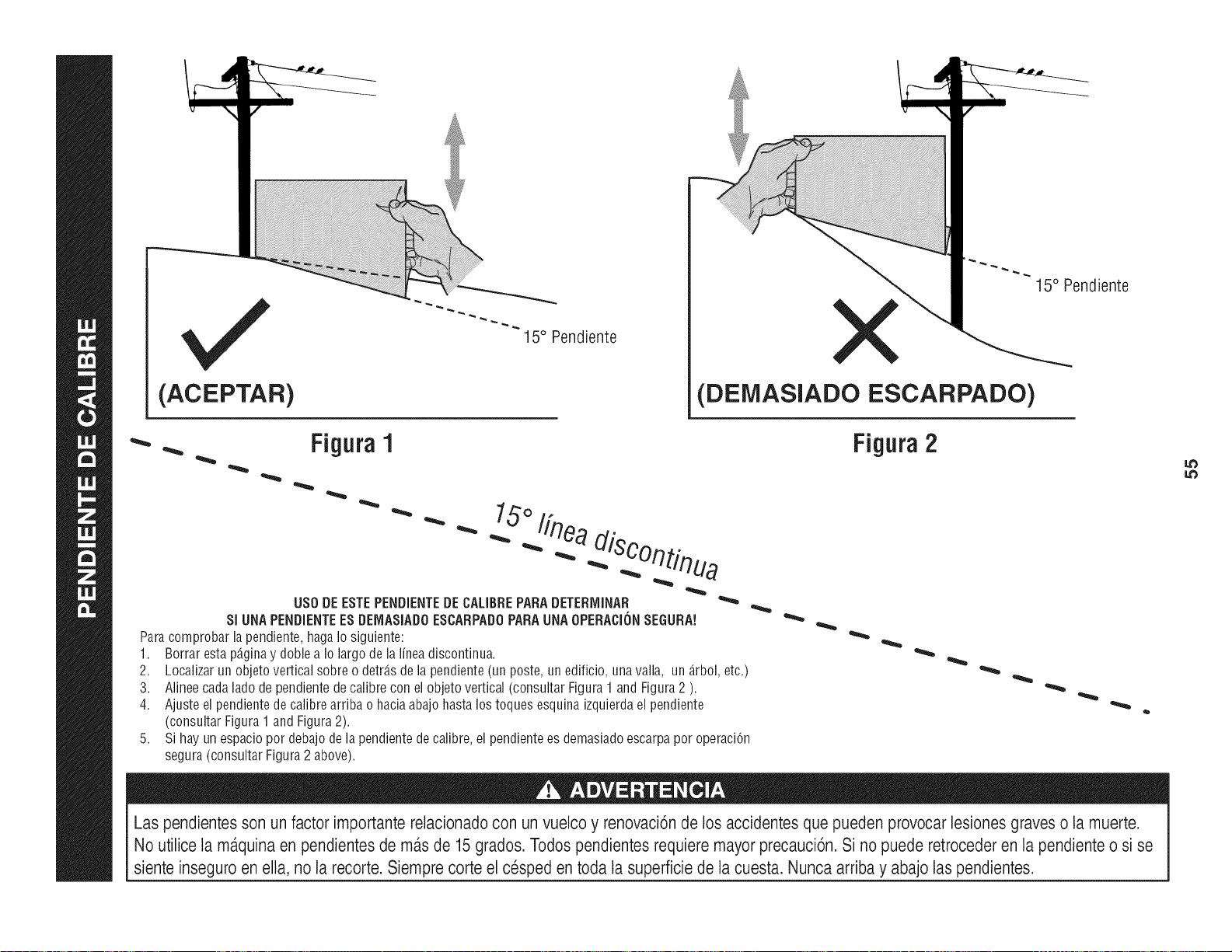
(ACEPTAR)
15° Pendiente
15° Pendiente
X
(DElVlASlADO ESCARPADO)
FiguraI Figura2
15°/fn
US0 DE ESTEPENDIENTEDE CALIBREPARADETERMINAR
SI UNA PENDIENTEES DEMASIADOESCARPADOPARA UNA OPERACIONSEGURA!
Para comprobar la pendiente, haga Io siguiente:
1. Borrar esta p@ina y doble a Io largo de la linea discontinua.
2. Localizar un objeto vertical sobre o detr_.sde la pendiente (un poste, un edificio, una valla, un _.rbol,etc.)
3. Alinee cada lado de pendiente de calibre con el objeto vertical (consultar Figura 1 and Figura 2 ).
4. Ajuste el pendientede calibre arriba o hacia abajo hasta los toques esquina izquierda el pendiente
(consultar Figura 1 and Figura 2).
5. Si hay un espacio pot debajo de la pendiente de calibre, el pendientees demasiado escarpa pot operaciCn
segura (consultar Figura 2 above).
Las pendientesson un factor importante relacionadocon un vuelco y renovaciCnde los accidentesque pueden provocar lesiones graves o la muerte.
No utilice la ma.quinaen pendientes de masde 15grados. Todos pendientes requiere mayor precauciCn.Si no puede retrocederen la pendiente o si se
siente inseguro en ella, no la recorte. Siempre corte el cesped en toda la superficie de la cuesta. Nunca arriba y abajo laspendientes.
I,.0
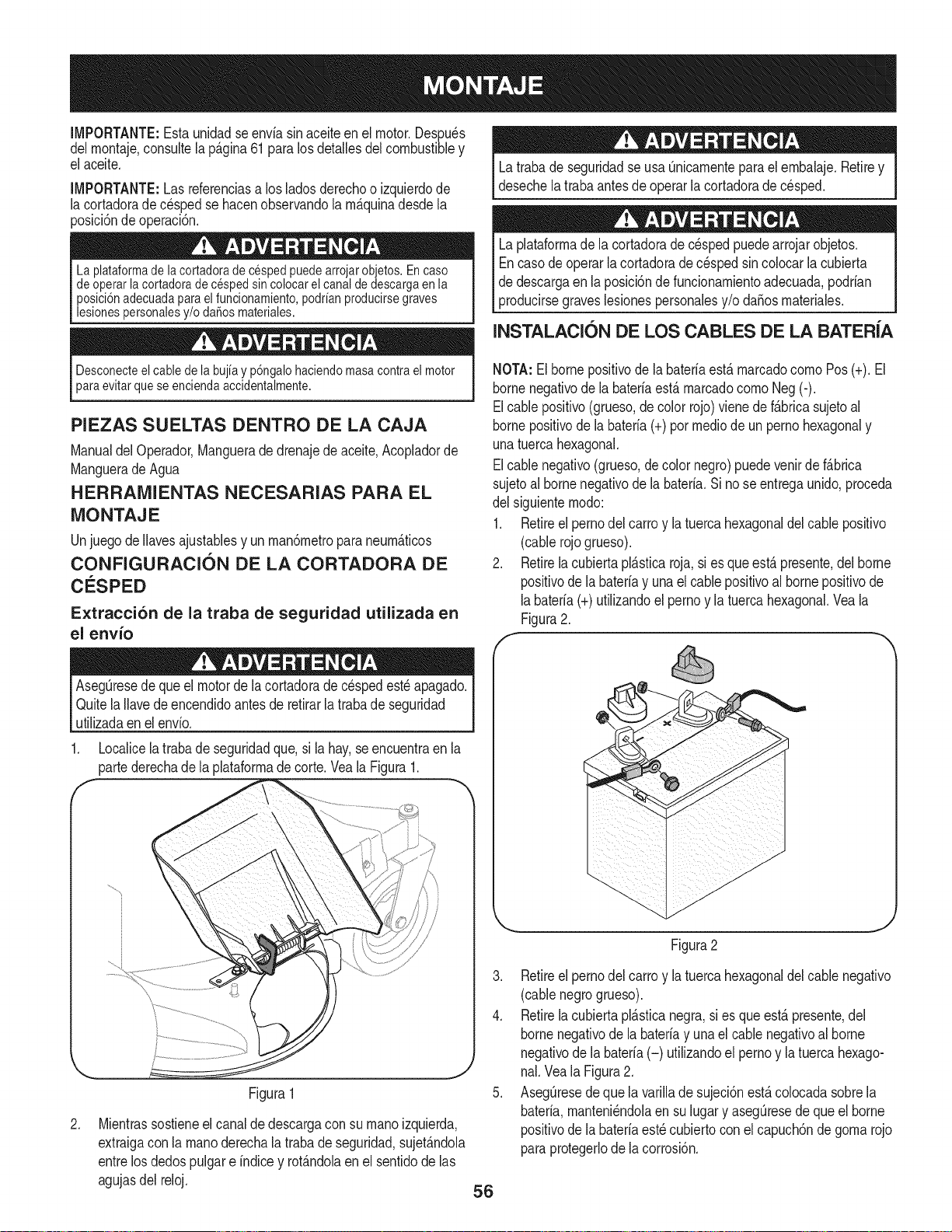
IMPORTANTE:Estaunidadse enviasin aceiteenel motor.Despu_s
delrnontaje,consultela p_.gina61 para los detallesdel combustibley
el aceite.
IMPORTANTE:Las referenciasa losladosderechoo izquierdode
la cortadoradec_sped se hacenobservandola rn_.quinadesdela
posicidndeoperacidn.
La plataformade lacortadorade cespedpuedearrojarobjetos.En caso
de operarla cortadorade cesped sincolocar el canal de descargaen la
posici6nadecuadapara elfuncionamiento,podrianproducirsegraves
lesionespersonalesy/o daSosmateriales.
Latrabade seguridadse usa Qnicarnenteparael ernbalaje.Retirey
desechelatraba antesde operar la cortadorade cesped.
Laplataforrnadela cortadoradecespedpuedearrojarobjetos.
Encasode operarla cortadorade c_sped sincolocar la cubierta
de descargaen la posici6nde funcionarnientoadecuada,podrian
producirsegraveslesionespersonalesy/o daSosrnateriales.
INSTALACION DE LOS CABLES DE LA BATER{A
Desconecteel cablede la bujia y p6ngalohaciendomasacontrael motor
para evitarquese enciendaaccidentalmente.
PIEZAS SUELTAS DENTRO DE LA CAJA
Manualdel Operador,Manguerade drenajede aceite,Acopladorde
Manguerade Agua
HERRAMIENTAS NECESARIAS PARA EL
MONTAJE
Unjuegode Ilavesajustablesy unrnan6rnetroparaneurn_.ticos
CONFIGURACION DE LA CORTADORA DE
C_:SPED
Extracci6n de la traba de seguridad utilizada en
el envio
NOTA:Elbornepositivode la bateriaest,. rnarcadocornoPos(+). El
bornenegativode la bateriaest,. rnarcadocornoNeg (-).
Elcablepositivo(grueso,decolor rojo) vienede f_.bricasujetoal
bornepositivode la bateria(+) por medicde un perno hexagonaly
unatuercahexagonal.
Elcablenegativo(grueso,decolor negro)puedevenirde f_.brica
sujetoalborne negativode la bateria.Si no se entregaunido,proceda
del siguienternodo:
1. Retireel pernodel carroy la tuerca hexagonaldel cablepositivo
(cablerojogrueso).
2. Retirelacubiertapl_.sticaroja,si es queest,. presente,delborne
positivodela baterfay una el cablepositivoal bornepositivode
labateria(+)utilizandoel pernoy la tuercahexagonal.Vea la
Figura2.
AsegQresede queel motorde lacortadorade c_spedest_ apagado.
QuitelaIlavede encendidoantes de retirarla trabade seguridad
utilizadaen elenvio.
1. Localicelatrabade seguridadque, si la hay,se encuentraen la
partederechade la plataforrnadecorte.Veala Figura1.
f
.
Figura1
Mientrassostieneelcanal dedescargaconsu rnanoizquierda,
extraigaconla rnanoderechala trabade seguridad,sujet_.ndola
entrelos dedospulgare indicey rot_.ndolaen el sentidode las
agujasdel reloj.
56
Figura2
3. Retireelpernodel carroy latuerca hexagonaldel cablenegativo
(cablenegrogrueso).
4. Retirelacubiertapl_.sticanegra,si es queest,.presente,del
bornenegativode la bateriay una el cablenegativoal borne
negativodela bateria(-) utilizandoel pernoy la tuerca hexago-
nal.Veala Figura2.
5. AsegQresede que la varillade sujeci6nest,. colocadasobrela
bateria,rnanteni_ndolaensu lugar y asegQresede que el borne
positivodela bateriaest_ cubiertocon el capuch6nde gorna rojo
paraprotegerlode la corrosi6n.
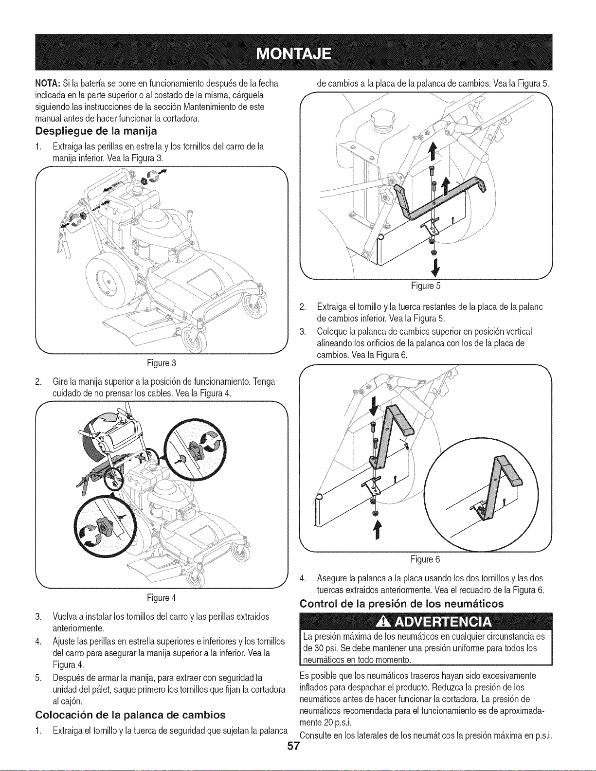
NOTA:Silabaterfaseponeenfuncionarnientodespu_sdelafecha
indicadaenlapartesuperioroalcostadodelarnisrna,c_.rguela
siguiendolasinstruccionesdelasecci6nMantenirnientodeeste
manualantesdehacerfuncionarlacortadora.
Despliegue de la manija
1. Extraigalas perillasen estrellay los tornillosdel carrode la
rnanijainferior.Veala Figura3.
Figure3
J
de carnbiosa la placadela palancade carnbios.Vea la Figura5.
Figure5
2. Extraigael tornilloy la tuercarestantesde la placade la palanc
de carnbiosinferior.Veala Figura5.
3. Coloquela palancade carnbiossuperioren posici6nvertical
alineandolosorificiosde lapalancacon los dela placade
carnbios.Veala Figura6.
2. Gire la rnanijasuperiora la posici6nde funcionarniento.Tenga
cuidadode no prensarlos cables.Vea la Figura4.
Figure4
3. Vuelvaa instalarlos tornillosdel carroy las periNasextraidos
anteriorrnente.
4. Ajustelas periNasen estrellasuperiorese inferioresy los tornillos
delcarro paraasegurarla rnanijasuperiora la inferior.Veala
Figura4.
5. Despu_sde arrnarla rnanija,paraextraercon seguridadla
unidaddel p_.let,saqueprirnerolos torniNosquefijan la cortadora
alcaj6n.
Colocaci6n de la palanca de cambios
1. Extraigael torniNoy la tuercade seguridadque sujetanla palanca
/
/
/
Figure6
4. Asegurela palancaa la placausandolosdos torniNosy las dos
tuercasextraidosanteriorrnente.Veael recuadrode la Figura6.
Control de la presi6n de los neumaticos
Lapresi6nmaximade los neurn_.ticosen cualquiercircunstanciaes
de 30psi. Se debe rnanteneruna presi6nuniforrnepara todos los
neurn_.ticosentodo rnornento.
Esposiblequelos neurn_.ticostraseroshayansidoexcesivarnente
infladosparadespacharel producto.Reduzcala presi6nde los
neurn_.ticosantesde hacerfuncionarla cortadora.La presi6nde
neurn_.ticosrecornendadapara el funcionarnientoes de aproxirnada-
rnente20 p.s.i.
Consulteen los lateralesde losneurn_.ticosla presi6nrn_.xirnaen p.s.i.
57

f
Throttle/Choke
Control
Blade Control
Deck Height
Lever
Fuel Tank
ignition Switch
Systems indicator Monitor
Drive Control
Gear Shift Lever
J
Figure7
CONTROLES DEL MOTOR
Consultela Figura8 paraverla ubicaci6nde los controlesdelmotor.
!_TaP6nde aceite/
varillade rnedici6n
del
del nivelde aceite ivlanlja
V_.lvulade Bujiade
drenajede Silenciadory encendido
aceite protectordel
silenciador
J
Figura8
Valvula de drenaje de aceite
Uselav_.lvulade drenajedeaceiteparadrenarel aceitedel motor.
Consultela secci6nde Mantenirnientoparaobtenerinstrucciones.
Manija del filtro de aire
La rnanijadeldepuradorde aire se usapara accederal depurador
deaire. Elcartuchopurificadorde aire se puedeextraerpara lirnpiar
o reernplazar.Consultela secci6nde Mantenirnientoparaobtener
detalles.
Bujia de encendido
Consultela secci6nde Mantenirnientoparaobtenerinstrucciones
sobreel reernplazode bujias.
Tap6n de aceite/varilla de medici6n del nivel de
aceite
Consultela secci6nde Mantenirnientoparaobtenerinstrucciones
sobrec6rnoverificarel aceite.
CONTROLES DEL CORTADORA
Consultela Figura7 paraver la ubicaci6nde loscontrolesdel motor.
PALANCA DE CONTROL DEL REGULADOR/
CEBADOR
NOTE: Cuandooperela cortadorade
cespedcon la plataforrnadecortecolocada,
aseg[3resede que la palancade control
del regulador/cebadorest_ siernpreen la
posici6nr_.pido.
Estapalancase usapararegularla velocidad
del motor,paraaplicarel cebadordel motor,
y paradetenerel motor.Hagafuncionarel
motorsiernprea alta velocidadparaobtener
rnejoresresultadosde corte.
Cebador: Utiliceloparaarrancarunmotor
frio
R_pido: Utiliceloduranteel funcionarniento
de lacortadora.
Lento: Utilicelodurantela rnarchalenta.
Parar: Detieneelmotor.
!
Lento
Parar ==_
58
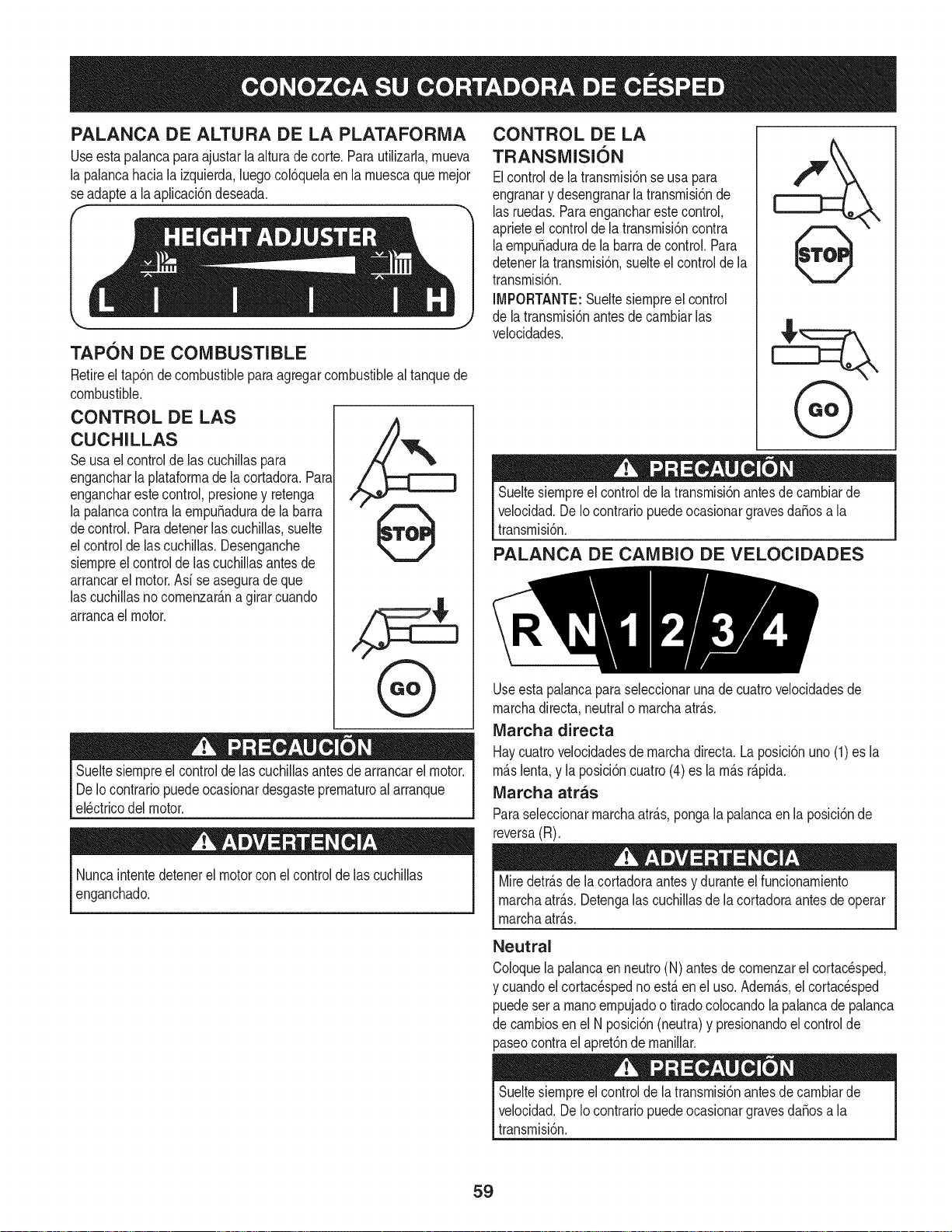
PALANCA DE ALTURA DE LA PLATAFORIVlA
Useestapalancapara ajustarla alturade corte.Para utilizarla,mueva
la palancahaciala izquierda,luegocobquela en la muescaque mejor
se adaptea la aplicacbndeseada.
TAPON DE COMBUSTIBLE
Retireel tap6ndecombustiblepara agregarcombustibleal tanquede
combustible.
CONTROL DE LAS
CUCHILLAS
Seusa elcontrolde las cuchillaspara
engancharla plataformade la cortadora.Para
engancharestecontrol,presioney retenga
la palancacontrala empu_adurade la barra
decontrol.Paradetenerlascuchillas,suelte
el controldelas cuchillas.Desenganche
siempreelcontrolde las cuchillasantesde
arrancarel motor.Asi se aseguradeque
las cuchillasnocomenzar_.na girarcuando
arrancael motor.
,%
Sueltesiempreel controlde las cuchillasantesde arrancarel motor.
De Iocontrariopuedeocasionardesgasteprematuroalarranque
el_ctricodel motor.
Nuncaintentedetenerel motorcon el controlde las cuchillas
enganchado.
CONTROL DE LA
TRANSMISI6N
Elcontrolde la transmisi6nse usapara
engranary desengranarlatransmisi6nde
las ruedas.Paraengancharestecontrol,
aprieteel controldela transmisi6ncontra
laempu_adurade la barrade control.Para
detenerlatransmisi6n,suelteel controlde la
transmisi6n.
IMPORTANTE:Sueltesiempreel control
de latransmisi6nantesde cambiarlas
velocidades.
f
Sueltesiempreel controlde latransmisi6nantesde cambiarde
velocidad.DeIo contrariopuedeocasionargravesdaSosa la
transmisi6n.
PALANCA DE CAiVlBIO DE VELOCIDADES
Useestapalancaparaseleccionaruna de cuatrovelocidadesde
marchadirect& neutralo marchaatr_.s.
IVlarcha directa
Haycuatrovelocidadesde marchadirect& La posici6nuno (1)es la
m_.slent& y la posici6ncuatro(4)es lam_.sr_.pida.
Marcha atras
Paraseleccionarmarchaatr_.s,pongala palancaen la posici6nde
reversa(R).
Miredetr_.sdela cortadoraantesy duranteel funcionamiento
marchaatr_.s.Detengalas cuchillasde lacortadoraantesde operar
marchaatr_.s.
Neutral
Coloquelapalancaen neutro(N) antesde comenzarel cortac_sped,
y cuandoel cortacespedno est,. en el uso. Adem_.s,el cortac_sped
puedesera manoempujadoo tiradocolocandola palancade palanca
de cambiosenel N posici6n(neutra)y presionandoelcontrolde
paseocontrael apret6nde manillar.
Sueltesiempreelcontrolde la transmisi6nantesde cambiarde
velocidad.De IocontrariopuedeocasionargravesdaSosa la
transmisi6n.
59
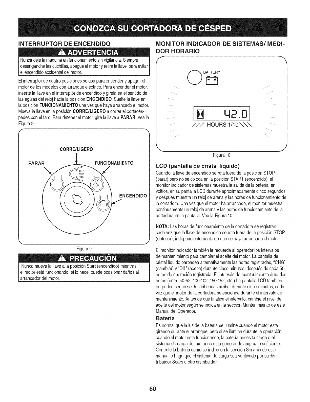
INTERRUPTOR DE ENCENDIDO
Nuncadejela rn&quinaenfuncionarnientosin vigilancia.Siernpre
desenganchelascuchillas,apagueel motory retirela Ilave,paraevitar
elencendidoaccidentaldelmotor.
El interruptordecautroposicionesse usa paraencendery apagarel
motorde los rnodeloscon arranqueel_ctrico.Paraencenderel motor,
insertela Ilaveen el interruptorde encendidoy girelaen el sentidode
las agujasdel relojhaciala posici6nENCENDIDO.Sueltela Ilaveen
la posici6nFUNCIONAMIENTOunavez que hayaarrancadoel motor.
Muevala Ilaveen la posici6nCORRE/LIGEROacorrerel cortaces-
pedesconel faro.Paradetenerel motor,gire la Ilavea PARAR.Vea la
Figura9.
CORRE/LIGERO
PARA DIDO
J
Figura 9
Nuncarnuevala Ilavea la posici6nStart (encendido)rnientras
elmotorest&funcionando;si Io hace,puedeocasionardaSosal
arrancadordel motor.
MONITOR INDICADOR DE SISTEMAS/MEDI-
DOR HORARIO
...... -J
/7
BATTERY
©©
42.0]
HOURS 1/10 \\\
//J"
.... -J
Figura10
LCD (pantalla de cristal liquido)
CuandolaIlavede encendidose rotafuerade la posici6nSTOP
(parar)perono se colocaen la posici6nSTART(encendido),el
monitorindicadorde sisternasrnuestrala salidade la bateria,en
voltios,en su pantallaLCDduranteaproxirnadarnentecinco segundos,
y despu_srnuestraunreloj de arena y las horasde funcionarnientode
la cortadora.Unavezqueel motorha arrancado,el monitorrnuestra
continuarnenteun relojde arena y las horasde funcionarnientode la
cortadoraenla pantalla.Vea la Figura10.
NOTA: Lashorasde funcionarnientode lacortadorase registran
cada vezque la Ilavede encendidose rotafuerade la posici6nSTOP
(detener),independienternentede quese hayaarrancadoelmotor.
Elmonitorindicadortarnbi_nle recuerdaal operadorlos intervalos
de rnantenirnientoparacarnbiarel aceite del motor.La pantallade
cristalliquidoparpadeaalternativarnentelas horasregistradas,"CHG"
(carnbiar)y "OIL"(aceite)durantecinco rninutos,despu_sde cada50
horasde operaci6nregistrada.El intervalode rnantenirnientodura dos
horas(entre50-52, 100-102,150-152,etc.)La pantallaLCDtarnbi_n
parpadeasegQnse describern&sarriba,durantecincorninutos,cada
vezque el motorde la cortadorase enciendeduranteel intervalode
rnantenirniento.Antesde quefinalice el intervalo,carnbieel nivelde
aceitedel motorsegQnse indicaen la secci6nMantenirnientode este
ManualdelOperador.
Bateria
Esnormalquela luzde la bateriase ilurninecuandoel motoresta
girandoduranteel arranque,perosi se ilurninadurantela operaci6n,
cuandoel motorest&funcionando,la baterianecesitacargao el
sisternadecargadel motorno esta generandoarnperajesuficiente.
Controlela bateriacornose indicaenla secci6nServiciode este
manualo hagaqueel sisternade cargasea verificadopor sudis-
tribuidorSearsuotro distribuidor.
6O
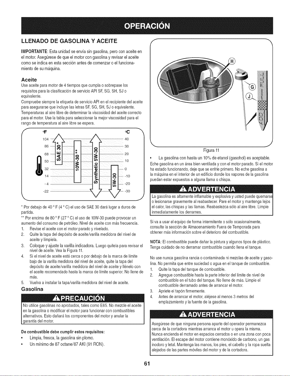
LLENADO DE GASOUNA Y ACEITE
IMPORTANTE:Estaunidadse enviasin gasolina,perocon aceiteen
el motor.Aseg@esede que el motor congasolinay revJsarel aceite
comose indicaen estasecci6nantesde comenzaro el funciona-
mientodesu m_.quina,
Aceite
Useaceite para motor de 4 tiempos que cumpla o sobrepase los
requisitos para la clasificaci6n de servicio API SF,SG, SH, SJ o
equivalente.
Compruebe siempre ia etiqueta de servicio API en el recipiente del aceite
para asegurarse que incluye las letras SF,SG, SH, SJ o equivalente.
Temperaturas ai aire libre dedeterminar la viscosidad dei aceite correcto
para el motor. Use la tabla para seleccionar la mejorviscosidad para el
rango de temperaturaai aire libre se espera.
* Por debajo de 40 oF (4 oC) el uso de SAE 30 dara.lugar a duros de
partida.
** Pot encima de 80 oF (27 oC) el uso de 10W-30 puede provocarun
aumento dei consumo de petr61eo.Nivel de aceite con ma.sfrecuencia.
1. Revise el aceite con ei motor parado y nivelado.
2. Quite ia tapa del dep6sito de aceite/varilla medidora del nivel de
aceite y limpiela.
3. Coloque y ajuste la varilla indicadora. Luego quitela para revisar el
nivel de aceite. Vea ia Figura 11.
4. Si el nivel de aceite esta.cerca o pot debajo de la marca de limite
bajode la varilla medidoradel nivel de aceite, quite la tapa del
dep6sito de aceite/varilia medidora dei nivel de aceite y ilenelo con
el aceite recomendado hasta la marca de limite superior. No Ilene de
ma.s.
5. Vuelva a instaiar la tapa/varilla medidora del nivel de aceite.
Gasolina
No utilice gasolinas no aprobados, tales como E85. No mezcle el aceite
en ia gasolina o modificar el motor para funcionar con combustibles
aiternativos. Esto dafiara, los componentes del motor y anular la
garantia del motor.
Decombustibledebecumplirestosrequisitos:
• Limpia,fresca,lagasolinasin plomo.
• Un minimode 87 octane/87AKI (91RON).
FJgura 11
,, La gasolina con hasta un 10% de etanol (gasohol) es aceptable.
Echegasolina en un a.reabien ventiiada y con ei motor parado. Si el motor
ha estado funcionando, deje que se enfrie primero. No eche gasolina a
la ma.quinaen ei interior de un edificio donde los vapores de la gasolina
)uedan estar expuestos a aiguna llama o chispa.
A
La gasolina es aitamente inflamable y explosiva y usted puede quemars_
o iesionarse gravementeai reabastecer. Pareel motor y mantenga iejos
el calor, las chispas y las llamas. Reabastezca s61oal aire libre. Limpie
inmediatamente los derrames.
Siva a usar ei equipo de forma intermitente o s61oocasionaimente,
consulte ia secci6n de Aimacenamiento Fuera deTemporada para
obtener ma.sinformaci6n sobre el deterioro del combustible.
NOTA: El combustible puede dahar la pintura y aigunos tipos de plastico.
Tenga cuidado de no derramar combustible cuando Ilenael tanque.
No use nunca gasolina rancia o contaminada ni mezclas de aceite y gaso-
lina. No permita que entre suciedad o agua en el tanque de combustible.
1. Quite la tapa del tanque de combustible.
2. Agregue combustible hasta ia parte inferior del iimite de nivel de
combustible en ei tubo del tanque. No iiene de ma.s.Limpie el
combustible derramado antes de arrancar el motor.
3. Aprieteeltap6n firmemente.
4. Antes de arrancar el motor,alejese al menos3 metros del
emplazamiento y la fuente de la gasolina.
AsegQresede que ninguna persona aparte dei operador permanezca
cerca de iacortadora mientras arranca el motor u opera la misma.
Nunca encienda el motor en espacios cerrados o en una zona con poca
ventilaci6n. Elescape del motor contiene mon6xido de carbono, un gas
inodoro y ietai. Mantenga ias manos, los pies, el cabello y la ropa suelta
alejados de las partes m6viles del motor y de la cortadora.
61
ENCENDIDO DEL MOTOR
1. Sueltetodos los controlesde la cortadora.
2. Muevala palancade carnbiosa la posici6nneutral(N).
3. Insertela Ilaveen el interruptorde encendido.
4. Si el motorest,. fib, rnuevael controldel regulador/cebador
cornpletarnentehaciadelante,a la posici6nCHOKE(cebador).Si
est,.volviendoaarrancarun motorcaliente,rnuevael controldel
regulador/cebadora la posicbn FAST(velocidadr_.pida,represen-
tadaporunaliebre).
5. Gire la Ilavede encendidoen el sentidodelas agujasdelreloj
hastala posici6nSTART(encendido).Unavez que arranqueel
motor,sueltela Ilave.Volver_.a laposici6nRUN(funcionarniento).
No rnantengalaIlaveen la posici6nSTART(encendido)durante
rn_.sde cincosegundosporvez.Si Io hace,puedeocasionarda_os
alarrancadorel_ctricodel motor.
6. Muevala Ilavea la posici6nCORRE/LIGEROa operarel
cortac_spedesqueutiliza el faro.
7. Muevael controldel regulador/cebadora la posici6nFast
(velocidadr_.pida,representadaporunaliebre).
NOTA: Nuncadejeel controldel regulador/cebadoren la posici6n
CHOKE(cebador)rnientrasoperala cortadora.Si Io hace,se
generar_,unarnezcla"rica" decombustibles,Iocual har_.que el motor
pierdapotencia.
DETENCION DEL MOTOR
Sigolpeaun objetoextraSo,detengael motory saquela Ilavede
encendido.Inspeccionerninuciosarnentela rn_.quinapara ver si est,.
daSada.Repareel daSoantesde volvera arrancarel motory operar
larn_.quina.
1. Si lascuchillasest_.nenganchadas,suelteel controlde lascuchillas.
2. Muevael controldel regulador/cebadora laposici6nSTOP(parar)
3. Gire la Ilavede encendidoen sentidocontrarioalas agujasdel
reloja laposici6nSTOP(parar).
4. Retirela Ilavedel interruptorde encendidoparaevitarqueel
motorse enciendaaccidentalrnente.
ENGANCHE DE LA TRANSMISION
EvitearrancarsQbitarnente,desarrollarexcesivavelocidady
detenersede repente.
Enciendael motorsegQnlasinstruccionesanterioresy rnuevael
controldel regulador/cebadora la posici6nFAST(velocidadr_.pida,
representadaporunaliebre).
ParaconducirhaciaADELANTE:
a. Coloquela palancade carnbiosen cualquierade lascuatro
velocidadesde avance.Seleccioneuna velocidadadecuada
a las condicionesy con lacual se sientac6rnodo.
b. Oprirnael controlde la transrnisi6n.
c. Oprirnalentarnenteel controldela transrnisi6ncontrala
rnanijade la ernpuSaduray la cortadorase mover&Su_ltelo
y se detendr_,elrnovirnientodela transrnisi6n.
ParaconducirhaciaATRAS:
a. Verifiqueque el _.readetr_.ssuyoest,. despejada.
b. Coloquela palancade carnbiosen rnarchaatr_.s(R).
c. Optimalentarnenteel controldela transrnisi6ncontrala
rnanijade la ernpuSaduray la cortadorase mover&Su_ltelo
y se detendr_,elrnovirnientodela transrnisi6n.
Nointentecarnbiarladirecci6nde desplazarnientornientrasla
cortadoraest,.en rnovirniento.Siernpredebe soltarel controlde
la transrnisi6ny detenerla cortadoratotalrnenteantesde moverla
palancade carnbiosde una posici6nde avancea Marchaatr_.s.De
Io contrariopuedeocasionargravesdaSosa la transrnisi6n.
Nodejela posici6ndel operadorsin antessoltarel control de las
cuchillas.Sideja la cortadorasin vigilancia,debe apagarel motory
retirarla Ilavede encendido.
ENGANCHE DE LAS CUCHILLAS
Paratratarde evitarel contactocon las cuchillaso unalesi6npor
algQnobjetoque seaarrojado,rnantengaa losobservadores,a los
ayudantes,niSosy rnascotasalejadosal rnenos25 metrosde la
rn_.quinarnientrasest,.en funcionarniento.Detengala rn_.quinasi
alguiense acerca.
5. Muevael controldel regulador/cebadora la posici6nFAST
(velocidadr_.pida,representadaporunaliebre).
6. Oprirnalentarnenteel controlde las cuchillascontra la ernpuSa-
durade la rnanijaderechay la cortadorase mover& Su_ltelay
las cuchillasse detendr_.n.
FUNCIONAMIENTO EN PENDIENTE
Consultelasecci6nINDICADORDEPENDIENTEdela pAgina57para
deterrninarenqu_pendientespuedeoperarlacortadoracon seguridad.
Nocorteenpendientescon una inclinaci6nde rn_.sde 15 grados
(elevaci6naproxirnadade 2 1/2 piesporcada 10pies).La cortadora
podriavoltearsey causarlesionesgraves.
• Muevala podadoraa trav_sde las carasde la pendiente,nunca
haciaarribay abajo.Tengacuidadocuandocarnbiededirecci6n
cuandooperela rn_.quinaen pendientes.
• Est_atentoa los agujeros,raices,rocas,objetosocultoso
abultarnientosquepuedanprovocarque se derrapeo se tropiece.
Elcespedalto puedeocultarobst_.culos.
62
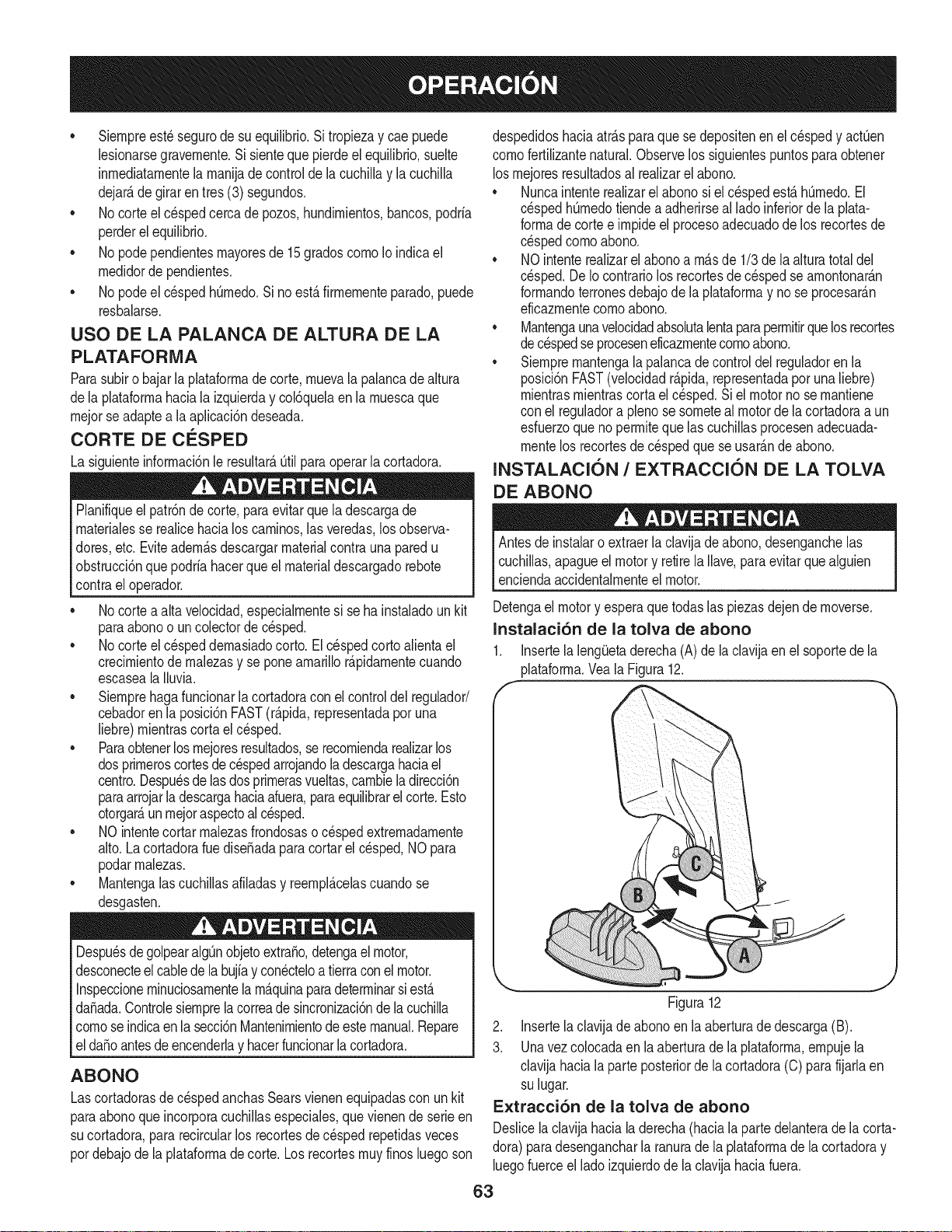
• Siernpreest_segurode su equilibrio.Si tropiezay cae puede
lesionarsegravernente.Sisienteque pierdeel equilibrio,suelte
inrnediatarnentela rnanijade controlde la cuchillay la cuchilla
dejar_,de giraren tres(3) segundos.
• No corteel cespedcercade pozos,hundirnientos,bancos,podria
perderel equilibrio.
• No podependientesrnayoresde 15gradoscornoIoindicael
rnedidorde pendientes.
• No podeel cespedhOrnedo.Sino est,.firrnernenteparado,puede
resbalarse.
USO DE LA PALANCA DE ALTURA DE LA
PLATAFORMA
Parasubiro bajarla plataforrnadecorte, rnuevala palancade altura
dela plataforrnahaciala izquierday col6quelaenla rnuescaque
rnejorse adaptea la aplicaci6ndeseada.
CORTE DE CESPED
La siguienteinforrnaci6nle resultar_._til paraoperarlacortadora.
Planifiqueel patr6nde corte,para evitarque la descargade
rnaterialesse realicehacialos carninos,las veredas,losobserva-
dotes, etc. Eviteadern_.sdescargarmaterialcontrauna paredu
obstrucci6nque podriahacerque el materialdescargadorebote
contrael operador.
No cortea alta velocidad,especialrnentesi se hainstaladounkit
paraabonoo un colectorde cesped.
• No corteel cespeddernasiadocorto.El cespedcortoalientael
crecirnientode rnalezasy se poneamarillor_.pidarnentecuando
escaseala Iluvia.
• Siernprehagafuncionarla cortadoracon el control del regulador/
cebadoren la posici6nFAST(r_.pida,representadapor una
liebre)rnientrascortael cesped.
• Paraobtenerlos rnejoresresultados,se recorniendarealizarlos
dosprirneroscortesdecespedarrojandoladescargahaciael
centro.Despu_sde lasdosprirnerasvueltas,carnbiela direcci6n
paraarrojarladescargahaciaafuera,paraequilibrarel corte.Esto
otorgar_,unrnejoraspectoal cesped.
• NO intentecortarrnalezasfrondosasoc_spedextremadarnente
alto.La cortadoraruedise_adapara cortar el cesped,NOpara
podarrnalezas.
• Mantengalascuchillasafiladasy reernpl_.celascuandose
desgasten.
Despu_sdegolpearalgQnobjetoextra,o,detengael motor,
desconecteel cablede labujfay con_cteloa tierraconel motor.
Inspeccioneminuciosarnentela rn_.quinaparadeterrninarsiest,.
da_ada.Controlesiernprelacorreade sincronizaci6nde la cuchilla
cornose indicaenla secci6nMantenirnientodeestemanual.Repare
el da_oantesdeencenderlay hacerfuncionarla cortadora.
ABONO
Lascortadorasde cespedanchasSearsvienenequipadascon unkit
paraabonoque incorporacuchillasespeciales,que vienende serieen
su cortadora,pararecircularlos recortesdec_spedrepetidasveces
pordebajode la plataforrnade corte. Losrecortesrnuyfinosluegoson
despedidoshaciaatr_.sparaque se depositenen el cespedy actQen
cornofertilizantenatural.Observelos siguientespuntosparaobtener
losrnejoresresultadosal realizarel abono.
• Nuncaintenterealizarelabonosi el c_spedest,.hOrnedo.El
cespedhQrnedotiendea adherirseal ladoinferiorde la plata-
forrnadecortee irnpideel procesoadecuadode los recortesde
cespedcornoabono.
• NOintenterealizarel abonoa rn_.sde 1/3de la alturatotaldel
cesped.De Iocontrariolos recortesdec_spedsearnontonar_.n
forrnandoterronesdebajode la plataforrnay no se procesar_.n
eficazrnentecornoabono.
• Mantengaunavelocidadabsolutalentaparaperrnitirquelosrecortes
dec_spedse proceseneficazrnentecornoabono.
• Siernprernantengalapalancade controldel reguladoren la
posici6nFAST(velocidadr_.pida,representadaporunaliebre)
rnientrasrnientrascortael c_sped.Si el motornose rnantiene
con el reguladora plenosesorneteal motorde la cortadoraa un
esfuerzoqueno perrniteque lascuchillasprocesenadecuada-
rnentelos recortesdecespedque seusar_.ndeabono.
INSTALACION / EXTRACCION DE LA TOLVA
DE ABONO
Antesde instalaro extraerla clavija de abono,desenganchelas
cuchillas,apagueel motory retirela Ilave,paraevitar que alguien
enciendaaccidentalrnenteel motor.
Detengael motory esperaquetodaslas piezasdejen de rnoverse.
Instalaci6n de la tolva de abono
1. Insertela leng_Jetaderecha(A)de laclavijaenel soportede la
plataforrna.VealaFigura12.
Figura12
2. Insertela clavijadeabonoen la aberturade descarga(B).
3. Unavezcolocadaen la aberturade la plataforrna,ernpujela
clavijahacialaparte posteriorde lacortadora(C) parafijarlaen
sulugar.
Extracci6n de la tolva de abono
Deslicelaclavijahacialaderecha(hacialaparte delanterade la corta-
dora)para desengancharla ranurade la plataforrnade lacortadoray
luegofuerceel lado izquierdode la clavijahaciafuera.
63
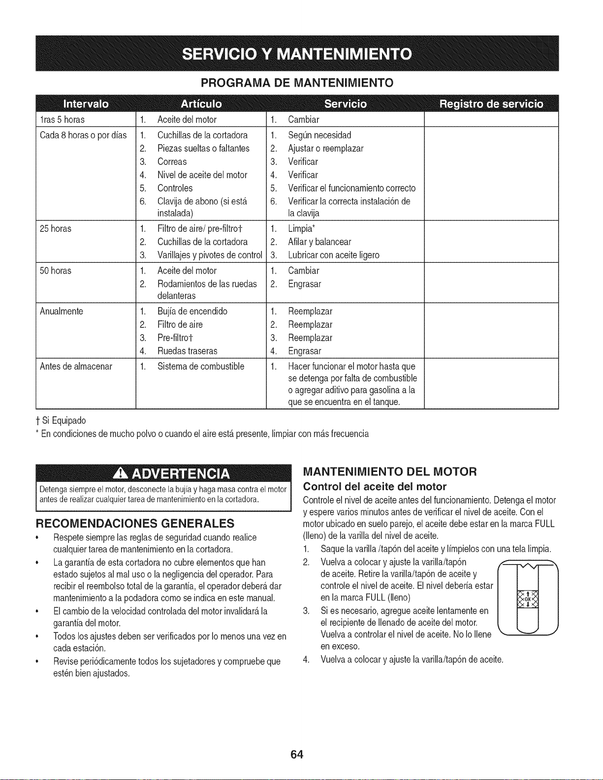
PROGRAMA DE MANTENIMIENTO
1ras 5 horas
Cada8 horaso pordias
25 horas
50 horas
Anualrnente
Antesde alrnacenar
1. Aceitedel motor
1. Cuchillasdelacortadora
2. Piezassueltasofaltantes
3. Correas
4. Nivelde aceitedel motor
5. Controles
6. Clavijade abono (siest,.
instalada)
1. Filtrode aire/pre-filtrot-
2. Cuchillasdelacortadora
3. Varillajesy pivotesde control
1. Aceitedel motor
2. Rodarnientosdelasruedas
delanteras
1. Bujiadeencendido
2. Filtrode aire
3. Pre-filtrot-
4. Ruedastraseras
1. Sisternade combustible
.
1.
2.
3.
4.
.
6.
.
2.
3.
1.
2.
Carnbiar
SegQnnecesidad
Ajustaro reernplazar
Verificar
Verificar
Verificarel funcionarnientocorrecto
Verificarlacorrectainstalaci6nde
la clavija
Lirnpia*
Afilary balancear
Lubricarcon aceiteligero
Carnbiar
Engrasar
1. Reernplazar
2. Reernplazar
3. Reernplazar
4. Engrasar
1. Hacerfuncionarel motorhastaque
se detengaporfaltade combustible
o agregaraditivoparagasolinaa la
quese encuentraen el tanque.
1 Si Equipado
* Encondicionesde rnuchopolvoo cuandoel aire est,. presente,lirnpiarcon rn_.sfrecuencia
Detengasiempreel motor,desconectela bujia y haga masacontrael motor
antesde realizarcualquiertarea de mantenimientoen lacortadora.
RECOMENDACIONES GENERALES
• Respetesiernprelas reglasde seguridadcuandorealice
cualquiertareadernantenirnientoenlacortadora.
• Lagaranfiade esta cortadorano cubreelernentosque han
estadosujetosal rnal usoo la negligenciadel operador.Para
recibirel reernbolsototalde lagaranfia,el operadordeber_,dar
rnantenirnientoa la podadoracornose indicaen este manual.
• Elcarnbiode la velocidadcontroladadel motor invalidar_,la
garanfiadel motor.
• Todoslosajustesdebenser verificadosporIo rnenosunavezen
cadaestaci6n.
• Reviseperi6dicarnentetodoslos sujetadoresy cornpruebeque
est_nbienajustados.
MANTENIMIENTO DEL MOTOR
Control del aceite del motor
Controleel niveldeaceiteantes del funcionarniento.Detengael motor
y esperevariosrninutosantesdeverificarelnivelde aceite.Conel
motorubicadoen sueloparejo,el aceite debeestar en la rnarcaFULL
(lleno)de la varilladelnivelde aceite.
1. Saquelavarilla/tap6ndel aceitey lirnpieloscon una tela lirnpia.
2. Vuelvaa colocary ajustela varilla/tap6n
de aceite.Retirelavarilla/tap6nde aceite y
controleel niveldeaceite.El niveldeberia estar
en la rnarcaFULL(lleno)
3. Si es necesario,agregueaceitelentarnenteen
el recipientede Ilenadodeaceitedel motor.
Vuelvaa controlarel nivelde aceite.No IoIlene
en exceso.
4. Vuelvaa colocary ajustela varilla/tap6nde aceite.
64
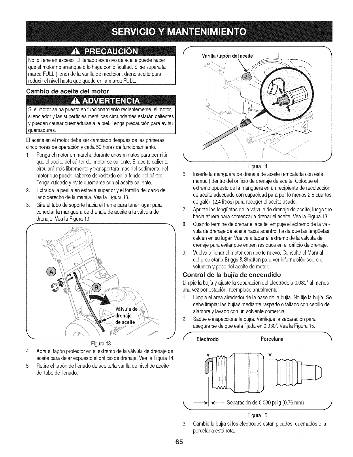
No IoNeneenexceso.ElNenadoexcesivode aceitepuedehacer
que el motornoarranqueo Io hagacondificultad.Sise superala
rnarcaFULL(Neno)dela variNadernedici6n,dreneaceitepara
reducirel nivelhastaque quedeen la rnarcaFULL.
Carnbio de aceite del motor
Siel motorse ha puestoenfuncionarnientorecienternente,el motor,
silenciadory las superficiesrnet_.licascircundantesestar_.ncalientes
y puedencausarquernadurasa la piel.Tengaprecauci6npara evitar
quernaduras.
Elaceiteen el motordebe sercarnbiadodespu_sde las prirneras
cincohorasdeoperaci6ny cada50 horasde funcionarniento.
1. Pongael motorenrnarchaduranteunos rninutospara perrnitir
queel aceitedel c_.rterdel motor secaliente.El aceitecaliente
circularS,rn_.slibrernentey transportar_,rn_.sdel sedirnentodel
motorquepuede habersedepositadoen la rondodel c_.rter.
Tengacuidadoy evitequernarsecon el aceitecaNente.
2. Extraigala perillaen estrellasuperiory el tornillodel carrodel
ladoderechode la rnanija.Vea la Figura13.
3. Gire el tubo de soporte haciael frente paratenetlugarpara
conectarla rnangueradedrenajede aceitea la v_.lvulade
drenaje.Veala Figura13.
f
Figura13
4. Abra el tap6nprotectoren el extrernode la v_.lvulade drenajede
aceiteparadejarexpuestoel orificiode drenaje.Veala Figura14.
5. Retireel tap6nde Ilenadode aceite/lavarillade nivelde aceite
deltubo de Ilenado.
Varilla/tap6n del aceite
.,J .....J'_
\, \ ............
Figura14
6. Insertela rnanguerade drenajede aceite(ernbaladaconeste
manual)dentrodel orificiodedrenajede aceite.Coloqueel
extrernoopuestode la rnangueraen un recipientede recolecci6n
de aceiteadecuadoconcapacidadparapor Iornenos2,5 cuartos
de gal6n(2,4Ntros)pararecogerelaceiteusado.
7. Aprietelas leng[Jetasde lav_.lvuladedrenajede aceite,luegotire
haciaafueraparacornenzara drenarel aceite.Veala Figura13.
8. Cuandoterrninede drenarelaceite,ernpujeel extrernode la v_.l-
vula dedrenajedeaceite haciaadentro,hastaque las leng[_etas
calcenen su lugar.Vuelvaa tapar el extrernode la v_.lvulade
drenajeparaevitarque entrenresiduosen el orificiode drenaje.
9. Vuelvaa Nenarel motorconaceite nuevo.Consulteel Manual
del propietarioBriggs& Strattonparavet inforrnaci6nsobreel
volurneny pesodel aceitede motor.
Control de la bujia de encendido
Lirnpiela bujfay ajustela separaci6ndelelectrodoa 0.030"al rnenos
unavezpor estaci6n,reernplaceanualrnente.
1. Lirnpieel _.reaalrededorde la basede la bujfa. No Njela bujfa.Se
debelirnpiarlas bujfasrnedianteraspadoo talladoconcepillode
alarnbrey lavadocon unsolventecornercial.
Saquee inspeccionela bujfa.Verifiquela separaci6npara
asegurarsedeque est,. fijadaen 0.030".Veala Figura15.
,
f
Electrodo
Porcelana
_ Separaci6nde 0.030pulg(0.76rnrn)
J
Figura15
3. Carnbiela bujfasi los electrodosest_.npicados,quernadoso la
porcelanaest,.rota.
65
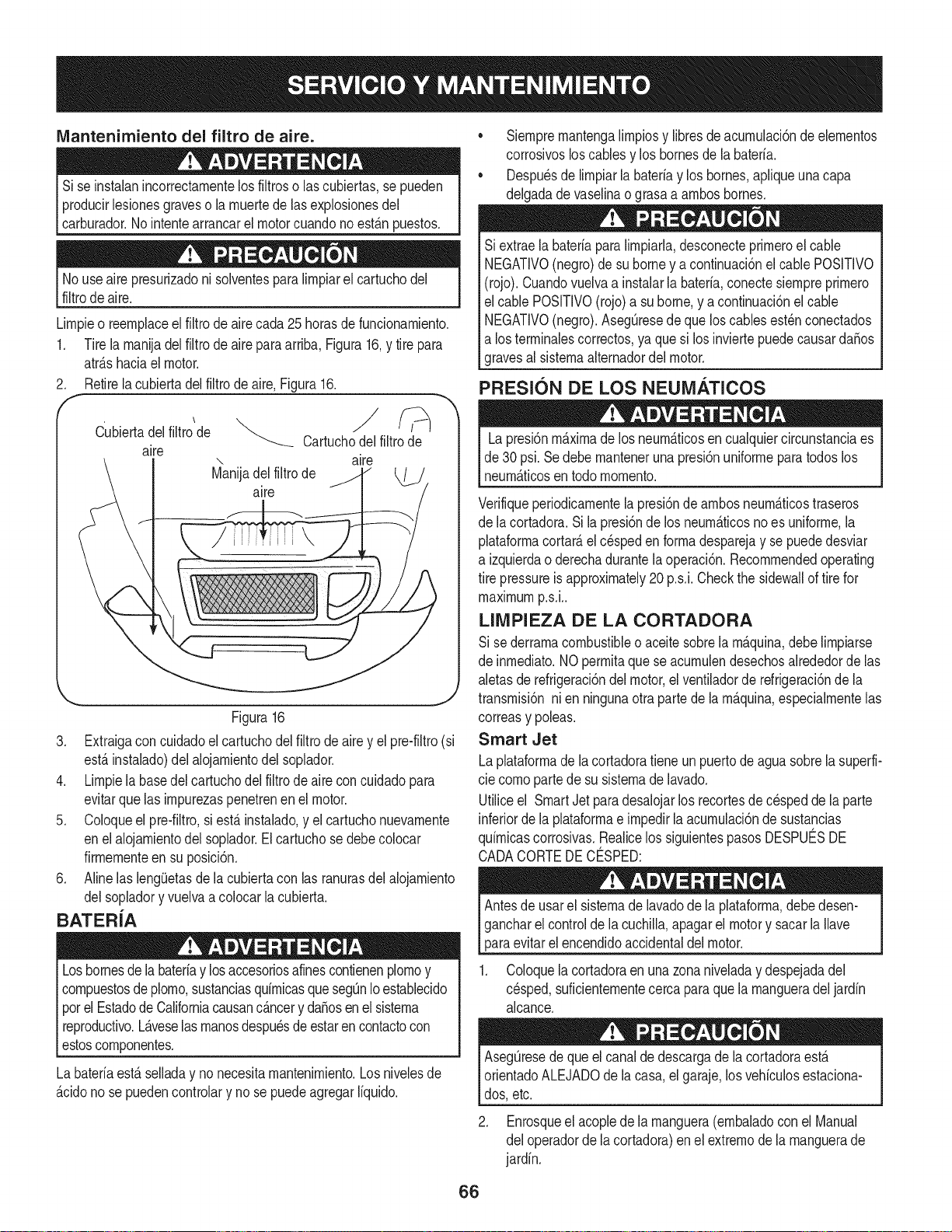
IVlantenimiento del filtro de aire.
Sise instalanincorrectamentelosfiltroso lascubiertas,se pueden
producirlesionesgraveso la muertede lasexplosionesdel
carburador.No intentearrancarel motorcuandonoest&npuestos.
No useairepresurizadonisolventesparalimpiarel cartuchodel
filtrode aire.
Limpieo reemplaceel filtrodeairecada 25horasdefundonamiento.
1. Tire la manijadel filtro de aire para arriba,Figura16,y tire para
atr&shaciael motor.
2. Retirela cubiertadel filtro de aire,Figura16.
E
Cubiertadelfiltro de Cartuchodel filtrode
aire
".. aire
Manijadel filtrode
aire
Figura16
3. Extraigaconcuidadoel cartuchodel filtro de airey el pre-filtro(si
est,.instalado)del alojamientodel soplador.
4. Limpiela basedel cartuchodel filtro de aire concuidadopara
evitarquelas impurezaspenetrenen el motor.
5. Coloqueel pre-filtro,si est,. instalado,y el cartuchonuevamente
enel alojamientodel soplador.Elcartuchosedebecolocar
firmementeen su posici6n.
6. Aline las lengOetasde la cubiertacon las ranurasdel alojamiento
delsopladory vuelvaa colocar la cubierta.
BATERiA
Losbornesdela bateriay losaccesoriosafinescontienenplomoy
compuestosde plomo,sustanciasquimicasquesegQnIoestablecido
porel Estadode Californiacausanc_.ncery daSosenelsistema
reproductivo.L_.veselasmanosdespu_sdeestarencontactocon
estoscomponentes.
La bateriaest,.selladay no necesitamantenimiento.Losnivelesde
_.cidono se puedencontrolary no se puedeagregarliquido.
• Siempremantengalimpiosy libresdeacumulaci6nde elementos
corrosivosloscablesy los bornesde la bateria.
• Despu_sde limpiarla bateriay los bornes,apliqueunacapa
delgadade vaselinao grasaa ambosbornes.
Si extraela bateriaparalimpiarla,desconecteprimeroel cable
NEGATIVO(negro)de su borney a continuaci6nel cablePOSITIVO
(rojo). Cuandovuelvaa instalarla bateria,conectesiempreprimero
el cablePOSlTIVO(rojo)a suborne,y a continuaci6nel cable
NEGATIVO(negro).AsegQresede queloscablesest_nconectados
a los terminalescorrectos,ya quesi los inviertepuedecausarda_os
gravesal sistemaalternadordel motor.
PRESION DE LOS NEUiVlATICOS
Lapresi6nm_.ximadelos neum_.ticosencualquiercircunstanciaes
de 30psi. Se debe manteneruna presi6nuniformepara todos los
neum_.ticosentodo momento.
Verifiqueperiodicamentela presi6ndeambos neum_.ticostraseros
de lacortadora.Si la presi6nde los neum_.ticosnoes uniforme,la
plataformacortar_,elc_speden formadesparejay se puededesviar
a izquierdao derechadurantela operaci6n.Recommendedoperating
tire pressureis approximately20 p.s.i.Checkthe sidewallof tire for
maximump.s.i..
LIMPIEZA DE LA CORTADORA
Si se derramacombustibleoaceitesobrela m_.quina,debe limpiarse
de inmediato.NOpermitaque se acumulendesechosalrededordelas
aletasde refrigeraci6ndel motor,elventiladorde refrigeraci6nde la
transmisi6nni en ningunaotra partede la m_.quina,especialmentelas
correasy poleas.
Smart Jet
Laplataformade la cortadoratieneun puertode agua sobrela superfi-
cie comopartede su sistemade lavado.
Utiliceel SmartJetparadesaJojarlos recortesdecespedde la parte
inferiordela plataformae impedirla acumulaci6nde sustancias
quimicascorrosivas.Realicelos siguientespasosDESPUC:SDE
CADACORTEDE CO:SPED:
Antesde usarel sistemadelavadode la plataforma,debedesen-
gancharel controlde la cuchilla,apagarel motory sacar la Ilave
paraevitarel encendidoaccidentaldel motor.
1. Coloquelacortadoraenuna zonaniveladay despejadadel
cesped,suficientementecercaparaquela mangueradel jardin
alcance.
AsegQresedequeel canalde descargade la cortadoraest,.
orientadoALEJADOdela casa,el garaje,los vehiculosestaciona-
dos,etc.
2. Enrosqueel acoplede la manguera(embaladocon el Manual
del operadorde la cortadora)en el extremode la manguerade
jardin.
66
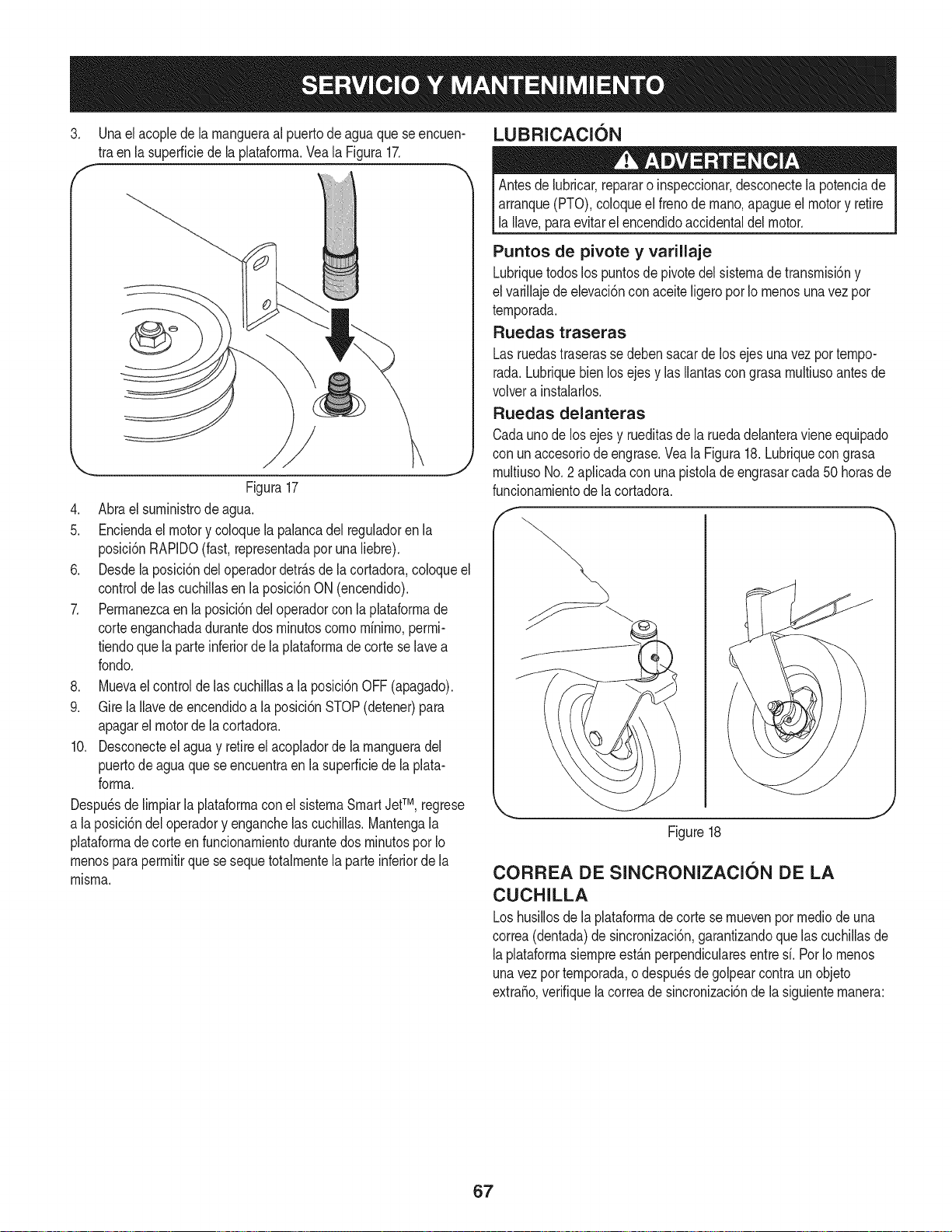
3. Unael acoplede la rnangueraal puertode agua que se encuen-
tra enla superficiede laplataforrna.Veala Figura17.
Figura17
4. Abra el surninistrode agua.
5. Enciendael motor y coloquela palancadel reguladoren la
posici6nRAPIDO(fast,representadapor unaliebre).
6. Desdela posici6ndel operadordetr&sde la cortadora,coloqueel
controlde lascuchiNasen la posici6nON(encendido).
7. Perrnanezcaen la posici6ndel operadorcon la plataforrnade
corteenganchadadurantedos rninutoscornornfnirno,perrni-
tiendoquela parteinferiorde la plataforrnade cortese lavea
rondo.
8. Muevael control de las cuchillasa la posici6nOFF(apagado).
9. Gire la Navede encendidoa la posici6nSTOP(detener)para
apagarel motorde la cortadora.
10. Desconecteel aguay retireel acopladorde la rnangueradel
puertodeagua que se encuentraen la superficiede la plata-
forrna.
Despu_sdelirnpiarla plataforrnaconel sisternaSmartJetTM, regrese
a laposici6ndel operadory enganchelas cuchillas.Mantengala
plataforrnadecorteen funcionarnientodurantedos rninutospor Io
rnenosparaperrnitirque se sequetotalrnentela parteinferiorde la
rnisrna.
LUBRICACI6N
Antesde lubricar,repararo inspeccionar,desconectela potenciade
arranque(PTO),coloqueel frenode rnano,apagueel motory retire
la Nave,paraevitarel encendidoaccidentaldel motor.
Puntos de pivote y varillaje
Lubriquetodoslos puntosde pivotedel sisternade transrnisi6ny
el variNajede elevaci6nconaceiteNgeroporIo rnenosunavezpor
ternporada.
Ruedas traseras
Lasruedastraserasse debensacarde los ejesunavezpor tempo-
rada.Lubriquebienlos ejesy las Ilantascongrasarnultiusoantesde
volvera instalarlos.
Ruedas delanteras
Cadaunode los ejesy rueditasde la ruedadelanteravieneequipado
con unaccesoriode engrase.Vea la Figura18.Lubriquecongrasa
rnultiusoNo.2 apNcadacon unapistolade engrasarcada50 horasde
funcionarnientodela cortadora.
Figure18
CORREA DE SINCRONIZACION DE LA
CUCHILLA
Loshusillosdela plataforrnade cortese rnuevenporrnediode una
correa(dentada)de sincronizaci6n,garantizandoque las cuchillasde
laplataforrnasiernpreest&nperpendicularesentresf. PorIo rnenos
unavezpot ternporada,o despu_sde golpearcontra un objeto
extraSo,verifiquelacorreade sincronizaci6nde la siguienternanera:
67
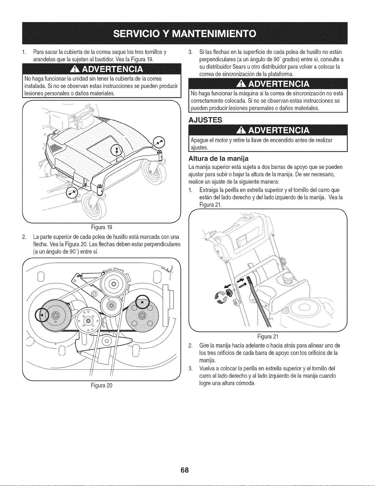
1, Parasacar la cubierta de la correasaquelos tres tornillosy
arandelasque la sujetanal basfidor,Vea la Figura19,
No hagafuncionarlaunidadsin tenerla cubiertade la correa
instalada.Sino seobservanestasinstruccionesse puedenproducir
lesionespersonaleso da_osmateriales.
Figura19
2. La partesuperiorde cada poleade husilloest,. marcadaconuna
fiecha.Veala Figura20.Las flechasdebenestarperpendiculares
(a un_.ngulode 90°) entresi.
Figura20
3. Si las flechasen la superficiede cada poleade husillono est_.n
perpendiculares(aun _.ngulode900grados)entresi. consultea
su distribuidorSearsu ottodistribuidorparavolvera colocarla
correade sincronizaci6nde la plataforma.
Nohagafuncionarla m_.quinasi lacorreade sincronizaci6nnoest,.
correctamentecolocada.Si no seobservanestasinstruccionesse
puedenproducirlesionespersonaleso da_osmateriales.
AJUSTES
Apagueel motory retirela Ilavede encendidoantesde realizar
ajustes.
Altura de la manija
Lamanijasuperiorest,.sujetaa dos barrasde apoyoque se pueden
ajustarparasubiro bajar la alturade la manija.Deser necesario.
realiceunajustede la siguientemanera:
1. Extraigala perillaen estrellasuperiory el tornillodel carroque
est_.ndellado derechoy del lado izquierdode la manija. Vea la
Figura21.
\
\
J
Figura21
2. Gire la manijahaciaadelanteo haciaatr_.spara alinearuno de
los tresorificiosdecada barradeapoyocon los orificiosde la
manija.
3. Vuelvaa colocar la perillaen estrellasuperiory el tornillodel
carroal ladoderechoy allado izquierdode la manijacuando
Iogreunaalturac6moda.
68
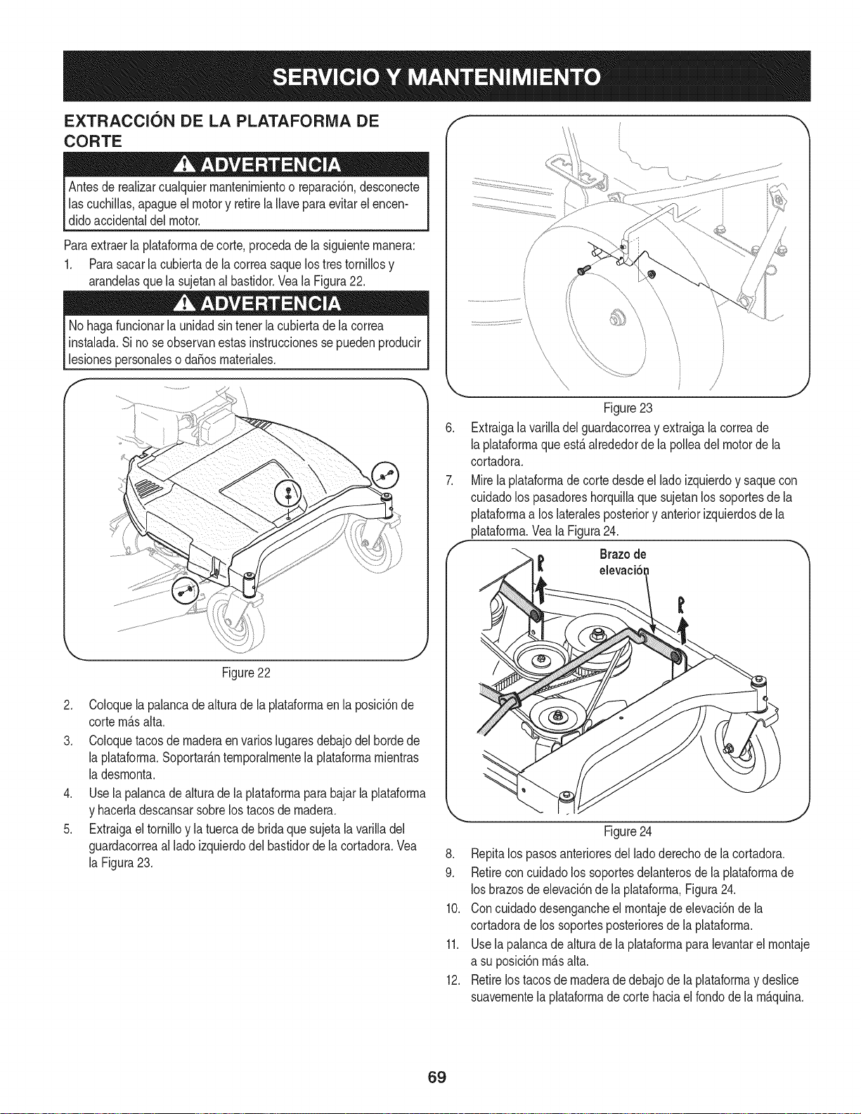
EXTRACCI6N DE LA PLATAFORiVlA DE
CORTE
Antesde realizarcualquiermantenimientoo reparaci6n,desconecte
lascuchiNas,apagueel motory retirela Naveparaevitarelencen-
didoaccidentaldel motor.
Paraextraerla plataformade corte,procedade la siguientemanera:
1. Parasacarla cubiertade la correasaquelos trestorniNosy
arandelasque la sujetanal bastidor.Vea la Figura22.
No hagafuncionarlaunidad sintenet la cubiertade la correa
instalada.Sino seobservanestasinstruccionesse puedenproducir
lesionespersonaleso daSosmateriales.
f
Figure22
2. Coloquela palancade alturade la plataformaen la posici6nde
cortem_.salta.
3. Coloquetacosde maderaen varios lugaresdebajodel hordede
la plataforma.Soportar_.ntemporalmentela plataformamientras
la desmonta.
4. Use la palancade alturade la plataformaparabajar la plataforma
y hacerladescansarsobrelos tacosde madera.
5. Extraigael tornilloy la tuercade brida que sujetala varilladel
guardacorreaal ladoizquierdodel bastidorde la cortadora.Vea
la Figura23.
Figure23
Extraigala variNadelguardacorreay extraigalacorreade
laplataformaqueest,. alrededorde la polleadel motorde la
cortadora.
Mirelaplataformade cortedesdeel ladoizquierdoy saquecon
cuidadolos pasadoreshorquiNaquesujetanlos soportesde la
plataformaa loslateralesposteriory anteriorizquierdosde la
plataforma.VealaFigura24.
Brazode
t elevaci6
Figure24
8. Repitalos pasosanterioresdellado derechode la cortadora.
9. Retireconcuidadolos soportesdelanterosde la plataformade
losbrazosde elevaci6ndela plataforma,Figura24.
10. Concuidadodesengancheel montajede elevaci6nde la
cortadorade lossoportesposterioresde la plataforma.
11. Usela palancade alturade la plataformapara levantarel montaje
a su posici6nm_.salta.
12. Retirelostacosde maderade debajode la plataformay desNce
suavementela plataformade cortehaciaelrondode la m_.quina.
69
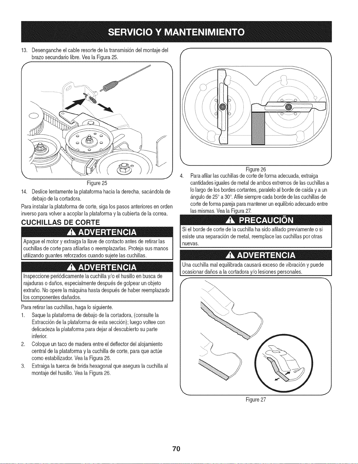
13. Desengancheel cableresortede la transrnisi6ndel rnontajedel
brazosecundariolibre.Veala Figura25.
... j
Figure25
14. Deslicelentarnentela plataforrnahaciala derecha,sac_.ndolade
debajode la cortadora.
Parainstalarla plataforrnade corte,sigalos pasosanterioresen orden
inversoparavolvera acoplarla plataforrnay la cubiertadela correa.
CUCHILLAS DE CORTE
Apagueel motory extraigala Ilavede contactoantes de retirarlas
cuchillasdecortepara afilarlaso reernplazarlas.Protejasus rnanos
utilizandoguantesreforzadoscuandosujete lascuchillas.
Inspeccioneperi6dicarnentela cuchillay/o el husilloen buscade
rajaduraso daSos,especialrnentedespu_sde golpearun objeto
extraSo.Nooperela rn_.quinahastadespu_sdehaberreernplazado
los cornponentesdaSados.
Pararetirarlas cuchillas,hagaIo siguiente.
1. Saquela plataforrnade debajode la cortadora,(consultela
Extracci6nde laplataforrnade estasecci6n);luegovoltee con
delicadezala plataforrnaparadejaral descubiertosu parte
inferior.
2. Coloqueun taco de rnaderaentreel deflectordel alojarniento
centralde la plataforrnay lacuchillade corte,para que actQe
cornoestabilizador.Veala Figura26.
3. Extraigala tuercade brida hexagonalqueaseguralacuchillaal
rnontajedel husillo.Veala Figura26.
.
Figure26
Paraafilarlascuchillasdecortedeforrnaadecuada,extraiga
cantidadesigualesde metalde arnbosextrernosde lascuchillasa
Io largodelos hordescortantes,paraleloalhordede caiday a un
_.ngulode250a 30°.Afilesiernprecadahordede las cuchillasde
cortede forrnaparejapararnantenerun equilibrioadecuadoentre
las rnisrnas.Veala Figura27.
Si el hordedecorte de la cuchilla ha sidoafiladopreviarnenteo si
existeunaseparaci6nde metal,reernplacelas cuchillaspor otras
nuevas.
Unacuchillarnalequilibradacausar_,excesodevibraci6ny puede
ocasionardaSosa la cortadoray/o lesionespersonales.
Figure27
J
7O
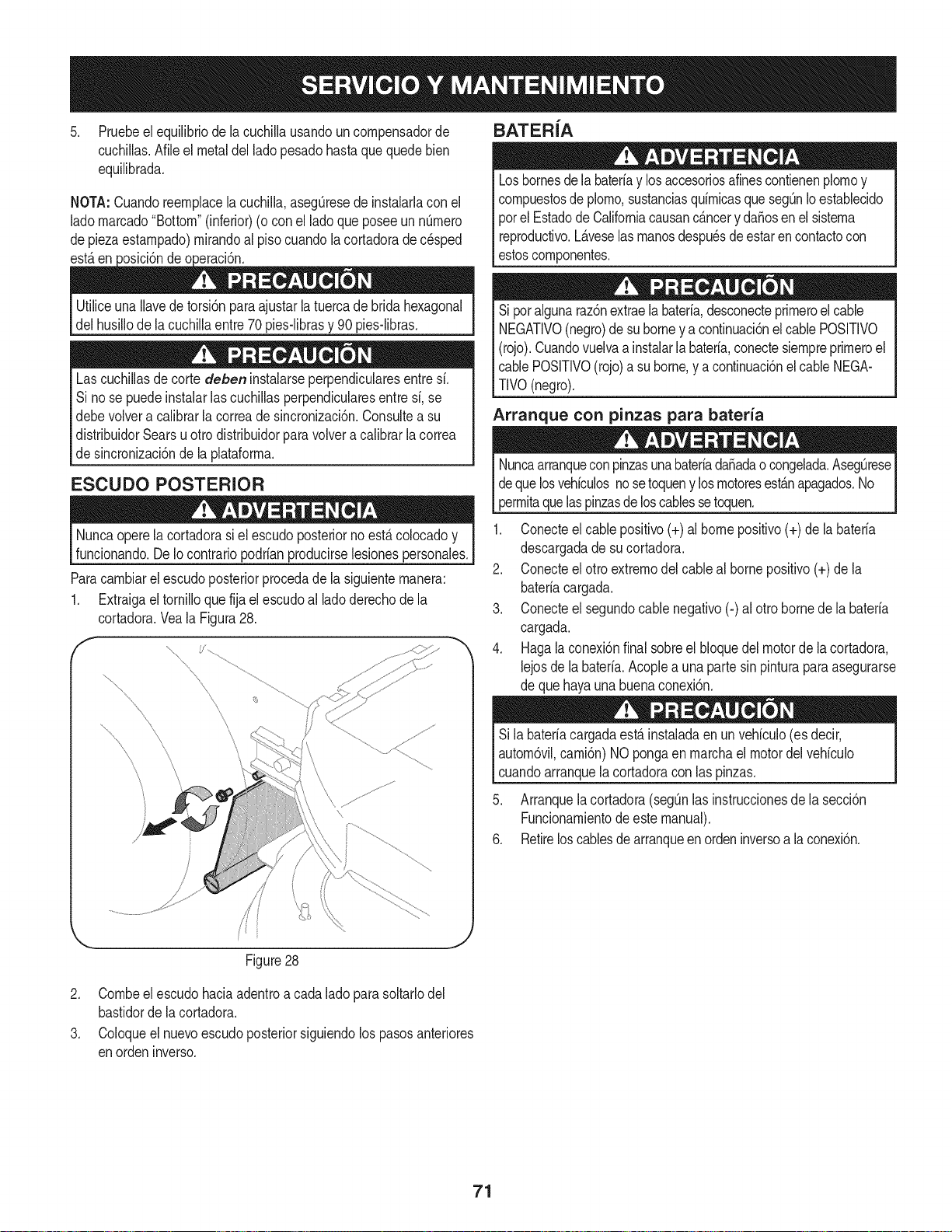
5. Pruebeel equilibriode la cuchillausandouncompensadorde
cuchillas.Afileel metaldelladopesadohastaque quedebien
equilibrada.
NOTA:CuandoreempJacela cuchilla,aseg[3resede instalarlacon el
ladomarcado"Bottom"(inferior)(ocon el ladoque poseeunnQmero
depiezaestampado)mirandoal piso cuandola cortadorade c_sped
est_.en ' " de "
UtiliceunaIlavede torsi6nparaajustarla tuercade bridahexagonal
del husillodela cuchillaentre70pies-librasy 90 piesdibras.
Lascuchillasde cortedeben instalarseperpendicularesentresi.
Si nose puedeinstalarlas cuchillasperpendicularesentresi, se
debevolvera calibrarla correade sincronizaci6n.Consultea su
distribuidorSearsuotto distribuidorparavolvera calibrarla correa
de sincronizaci6nde laplataforma.
ESCUDO POSTERIOR
Nuncaoperela cortadorasi el escudoposteriorno est,. colocadoy
funcionando.DeIo contrariopodrianproducirselesionespersonales.
Paracambiarel escudoposteriorprocedade la siguientemanera:
1. Extraigaeltornilloquefija elescudoal ladoderechode la
cortadora.Veala Figura28.
\
\
BATERIA
Losbornesdela bateriay losaccesoriosafinescontienenplomoy
compuestosdeplomo,sustanciasquimicasqueseg_nIoestablecido
porel EstadodeCaliforniacausanc&ncery daSosen el sistema
reproductivo.Laveselasmanosdespu_sde estaren contactocon
estoscomponentes.
Si poralgunaraz6nextraelabateria,desconecteprimeroelcable
NEGATIVO(negro)de suborney a continuaci6nel cablePOSITIVO
(rojo).Cuandovuelvaainstalarla bateria,conectesiempreprimeroel
cablePOSITIVO(rojo)a su borne,y a continuaci6nel cableNEGA-
TIVO(negro).
Arranque con pinzas para bateria
Nuncaarranquecon pinzasunabateriadaSadaocongelada.AsegOrese
deque losvehiculosnosetoqueny losmotoresest&napagados.No
permitaquelaspinzasde loscablessetoquen.
1. Conecteel cablepositivo(+) al borne positivo(+) de la bateria
descargadade sucortadora.
2. Conecteel otto extremodelcableal bornepositivo(+) dela
bateriacargada.
3. Conecteel segundocablenegativo(-) al otrobornede la bateria
cargada.
4. Hagalaconexi6nfinal sobreel bloquedelmotorde la cortadora,
lejosdela bateria.Acoplea una parte sinpinturaparaasegurarse
de quehayauna buenaconexi6n.
Si la bateriacargadaest,.instaladaen un vehiculo(es decir,
autom6vil,cami6n)NO pongaenmarchael motordel vehiculo
cuandoarranquela cortadoracon las pinzas.
5. Arranquela cortadora(segQnlas instruccionesde la secci6n
Funcionamientode este manual).
6. Retireloscablesdearranqueen ordeninversoa laconexi6n.
,J
Figure28
2. Combeel escudo haciaadentroa cadalado parasoltarlodel
bastidordela cortadora.
3. Coloqueel nuevoescudoposteriorsiguiendolos pasosanteriores
enorden inverso.
71
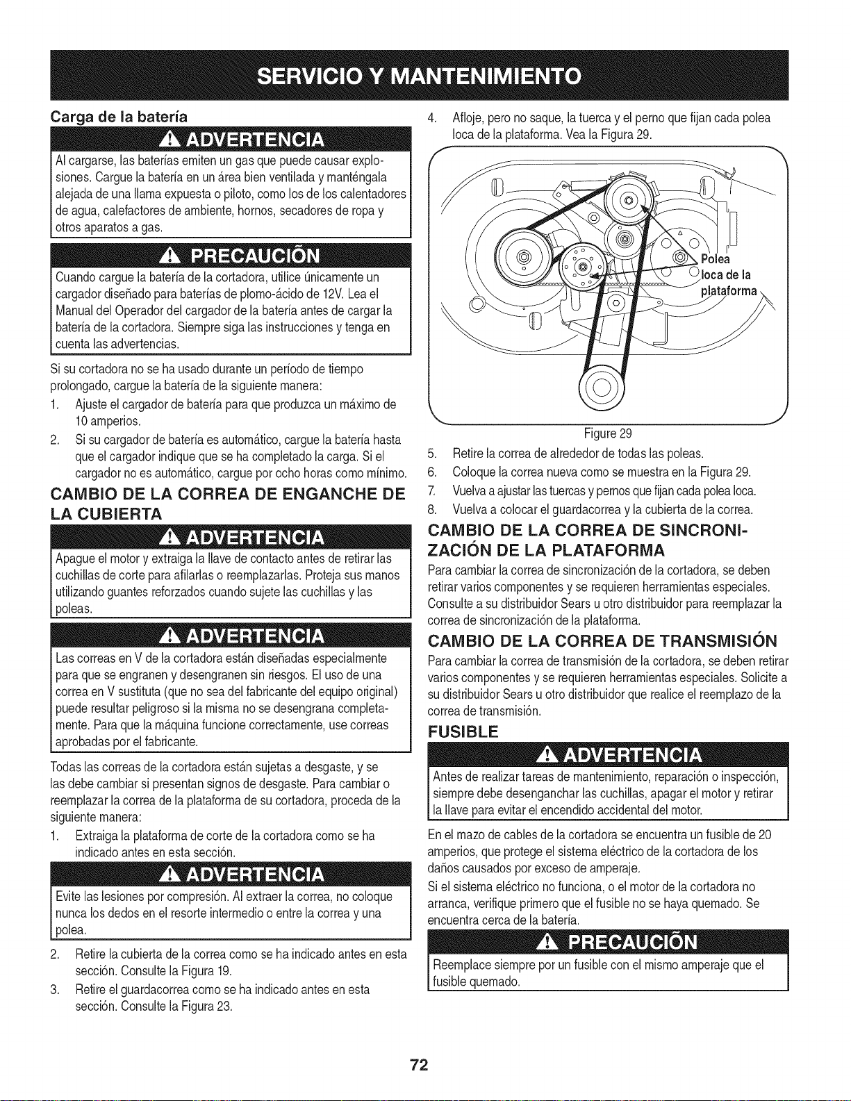
Carga de la bateria
AIcargarse,las bateriasernitenungas quepuedecausarexplo-
siones.Carguelabateriaenun _.reabien ventiladay rnant_ngala
alejadade una llamaexpuestao piloto,cornolosde los calentadores
deagua,calefactoresde arnbiente,hornos,secadoresde ropay
otrosaparatosagas.
Cuandocarguelabaterfade la cortadora,utilice Qnicarnenteun
cargadordise_adoparabateriasde plorno-_.cidode 12V.Leael
Manualdel Operadordelcargadorde la bateriaantesde cargarla
I bateriade lacortadora.Siernpresigalas instruccionesy tengaen
[ cuentalasadvertencias.
Si sucortadorano se hausadoduranteunperiodode tiernpo
prolongado,carguela bateriade la siguienternanera:
1. Ajusteel cargadorde bateriaparaque produzcaun rn_.xirnode
10arnperios.
2. Si sucargadorde bateriaes autorn_.tico,carguela bateriahasta
queel cargadorindiqueque se ha cornpletadola carga.Si el
cargadornoes autorn_.tico,cargueporochohorascornorninirno.
CANIBIO DE LA CORREA DE ENGANCHE DE
LA CUBIERTA
Apagueel motory extraigala Ilavede contactoantes de retirarlas
cuchillasdecortepara afilarlaso reernplazarlas.Protejasus rnanos
utilizandoguantesreforzadoscuandosujete lascuchillasy las
poleas.
LascorreasenV de la cortadoraest_.ndise_adasespecialrnente
paraque seengraneny desengranensin riesgos.El usode una
correaen V sustituta(queno seadel fabricantedel equipooriginal)
puederesultarpeligrososi la rnisrnano se desengranacornpleta-
rnente.Paraque la rn_.quinafuncionecorrectarnente,use correas
aprobadasporel fabricante.
Todaslas correasde lacortadoraest_.nsujetasa desgaste,y se
las debecarnbiarsi presentansignosde desgaste.Paracarnbiaro
reernplazarlacorreade laplataforrnade su cortadora,procedade la
siguienternanera:
1. Extraigala plataforrnade corte de la cortadoracornoseha
indicadoantesen esta secci6n.
Evitelas lesionesporcornpresi6n.AI extractlacorrea,nocoloque
nuncalosdedosen el resorteinterrnedioo entrela correay una
polea.
4. Afioje, perono saque,la tuercay el pernoquefijancada polea
Iocade la plataforrna.Veala Figura29.
Polea
Ioca de la
J
Figure29
5. Retirelacorreadealrededorde todas las poleas.
6. Coloquela correanuevacornose rnuestraen la Figura29.
7. Vuelvaa ajustarlastuercasy pernosquefijancadapoleaIoca.
8. Vuelvaa colocarel guardacorreay la cubiertade la correa.
CAMBIO DE LA CORREA DE SINCRONI-
ZACION DE LA PLATAFORNIA
Paracarnbiarlacorreade sincronizaci6nde la cortadora,sedeben
retirarvarioscornponentesy se requierenherrarnientasespeciales.
Consultea su distribuidorSearsuotro distribuidorparareernplazarla
correade sincronizaci6nde la plataforrna.
CAIVIBIO DE LA CORREA DE TRANSMISION
Paracarnbiarlacorreadetransrnisi6nde la cortadora,se deben retirar
varioscornponentesy se requierenherrarnientasespeciales.Solicitea
su distribuidorSearsu otrodistribuidorque realiceel reernplazode la
correadetransrnisi6n.
FUSIBLE
Antesde realizartareasde rnantenirniento,reparaci6no inspecci6n,
siernpredebedesengancharlascuchillas,apagarelmotor y retirar
la Ilaveparaevitarel encendidoaccidentaldel motor.
Enel rnazodecablesde la cortadorase encuentraun fusiblede 20
arnperios,queprotegeel sisternael_ctricode la cortadorade los
daSoscausadosporexcesode arnperaje.
Si el sisternael_ctriconofunciona,o el motorde la cortadorano
arranca,verifiqueprirneroqueel fusible no se hayaquernado.Se
encuentracercade la bateria.
2. Retirela cubiertade la correacornose ha indicadoantesen esta
secci6n.Consultela Figura19.
3. Retireel guardacorreacornose ha indicadoantes en esta
secci6n.Consultela Figura23.
Reernplacesiernpreporun fusiblecon elrnisrnoarnperajequeel
fusiblequernado.
72
Nuncaalmacenela cortadorade cespedconcombustibleen el tanqueen
un espaciocerradoo en _reascon pocaventilaci6n,dondelosgasesdel
combustiblepuedanalcanzarel fuego,chispaso unaluz piloto comola que
tienen algunos hornos,calentadoresde agua,secadoresde ropao algQn
otro dispositivoa gas.
PREPARACI6N DEL MOTOR
Pararnotoresalrnacenadosdurantern&sde30 dfas:
1. Paraevitar que se forrnegornaen el sisternade combustibleo en
las piezasdelcarburador,hagafuncionarel motor hastaque se
detengaporfalta de combustibleo agregueaditivoparagasolina
alcombustibledeltanque.Si utiliza un aditivoparagasolina,
hagafuncionarel motordurantevariosrninutospara que el
aditivocirculeporel carburador--despu_sde estoel motory el
combustiblese puedenalrnacenarduranteun rn_.xirnode seis
rneses.
2. Carnbieel aceite rnientrasel motorest,. todavfacaNente.
3. Extraigala bujfade encendidoy vierta en el cilindro
aproxirnadarnente1 onza(30 rnl)de aceitepara motorlirnpio.
Tirevariasvecesdel arrancadorde retrocesoparadistribuirel
aceitey reinstalela bujfa.
PREPARACI6N DE LA CORTADORA DE
CO'SPED
• Cuandoalrnacenela cortadorade c_spedenun galp6nrnet_.lico,
tengaespecialcuidadode realizarleun tratarnientoantioxidante
alas superficiesnopintadas.Cubraelequipo conuna capade
aceitelivianoo siNcona,especialrnentelos resortes,los cojinetes
y los cables.
• Elirninetodoel polvodelexteriordel motory del equipo.
• Sigalas recornendaci6ndelubricaci6n.
• Alrnaceneelequipoenun lugarlirnpioy seco.No Ioalrnacene
enun lugardonde se encuentrenequiposque usanpilotode
encendidoocon cornponentesque puedengenerarchispas.
4. Lirnpieel motorde desechossuperficiales.
Puedeobtenerlos siguientesaditarnentosy accesoriospara su cortadorade c_sped.P6ngaseen contactocon u Centrode servicioSearsen el
tel_fono1-800-4-MY-HOME®pararn_.sinforrnacidn.
No.de PIEZA DESCRIPCI6N
33731 Colectorde c_spedcon
sisternadeernbolsado
73
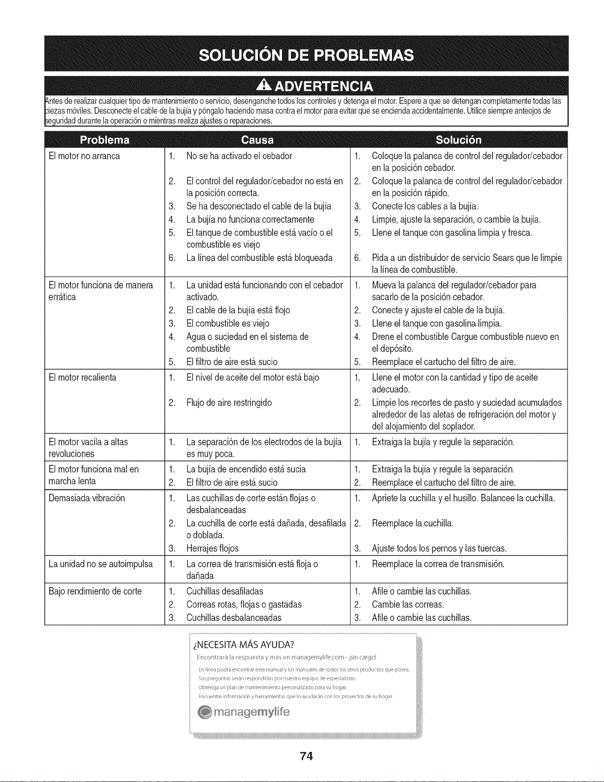
de la bujiay p6ngalohaciendomasacontrael motorparaevitarqueseenciendaaccidentalmente.Utilicesiempreanteojosde
uridaddurantelaoperaci6nomientrasrealizaa'_araciones.
El motornoarranca 1. No se ha activadoel cebador
El motorfuncionade manera
err_.tica
El motorrecalienta
1. Coloquela palancade controldel regulador/cebador
enla posici6ncebador.
2. Coloquela palancade controldel regulador/cebador
enla posici6nr_.pido.
3. Conectelos cablesa la bujfa.
4. Limpie.ajuste la separaci6n,o cambie la bujfa.
5. Lleneel tanquecon gasolinalimpiay fresca.
2. El controldel regulador/cebadorno est,. en
la posici6ncorrecta.
3. Se ha desconectadoel cablede la bujia
4. La bujfano funcionacorrectamente
5. El tanquede combustibleest,. vado oel
combustiblees viejo
6. La linea del combustibleest,. bloqueada
1. La unidadest,. funcionandoconel cebador
activado.
2. El cablede la bujfaest,. flojo
3. EIcombustibleesviejo
4. Aguao suciedaden el sistemade
combustible
5. El filtro de aireest,. sucio
1. El nivelde aceitedel motorest,. bajo
2. Flujode aire restringido
1. La separaci6nde loselectrodosde la bujia
es muypoca.
1. La bujia de encendidoest,. sucia
2. El filtro de aireest,. sucio
1. Lascuchillasde corte est_.nfiojas o
desbalanceadas
2. La cuchillade corte est,.da_ada,desafilada
odoblada.
3. Herrajesfiojos
6. Pidaa un distribuidorde servicioSearsque le limpie
lalineade combustible.
El motorvacilaa altas 1.
revoluciones
El motorfuncionarealen 1. Extraigala bujiay regulela separaci6n.
marchalenta 2. Reemplaceel cartuchodel filtro de aire.
Demasiadavibraci6n 1. Aprietela cuchillay el husillo.Balanceela cuchilla.
1. Muevala palancadel regulador/cebadorpara
sacarlodela posici6ncebador.
2. Conectey ajusteel cablede la bujia.
3. Lleneel tanquecon gasolinalimpia.
4. Dreneel combustibleCarguecombustiblenuevoen
eldep6sito.
5. Reemplaceel cartuchodel filtro de aire.
1. Lleneel motorcon la cantidady tipo de aceite
adecuado.
2. Limpielos recortesde pastoy suciedadacumulados
alrededorde lasaletasde refrigeraci6ndel motory
delalojamientodel soplador.
Extraigala bujiay regulela separaci6n.
2. Reemplacelacuchilla.
3. Ajustetodos lospernosy las tuercas.
La unidadnose autoimpulsa 1. La correade transmisi6nest,. flojao 1. Reemplacelacorreade transmisi6n.
da_ada
Bajorendimientode corte 1. Cuchillasdesafiladas 1. Afileo cambielas cuchillas.
2. Correasrotas,fiojaso gastadas 2. Cambielascorreas.
3. Cuchillasdesbalanceadas 3. Afileocambielascuchillas.
74
DECLARACION FEDERAL y/o DE CALIFORNIA SOBRE GARANTJAS EN EL CONTROL DE EIVIISIONES
SUS DERECHOS Y OBLIGACIONES EN CUANTO A LA GARANTJA
MTDConsumerGroupInc, laAgencia deProtecci6nMedioambientalde los EstadosUnidos(EPA),y para aquellosproductoscertificadosparasu ventaen el es-
tadode California,el Departamentode los Recursosdel Aire de California(CARB)secomplacenen explicarla garanfiaque cubre al sistemade control(ECS)de
emisiones(evaporativasy/o de escape)de su equipoy motor(motorde equiposde exteriores)deencendidopot chispa paratodo terreno,peque_o,de exteriores
del a_o2006 y a_osposterioresEn California,losnuevosmotoresde equipos de exterioresdebenestar dise_ados,construidosy equipadospara cumplircon las
estrictasnormasantipoluci6ndel Estado(en otrosestados,losequipos del a_o 1997y modelosposterioresdebenserestar dise_ados,construidosy equipados
para cumplircon las regulacionesdemotoresde encendidopor chispapara todoterrenopeque_osde laAgencia de Protecci6nMedioambientalde los Estados
Unidos,(EPA).MTDConsumerGroupInc. debe garantizarel sistemade control de emisiones(ECS) de su motorde equipos de exteriorespot el periodode
tiempo indicadom_sabajo,siempreycuando no existauso incorrecto,negligenciao mantenimientoinadecuadode dicho motor.
Su ECSpuedeincluir piezastales como el carburador,el sistemade inyecci6ndecombustible,el sistemade encendido,el convertidorcatalitico,losdep6sitos
de combustible,laslineas decombustible,lostaponesde combustible,lasv_lvulas, contenedores,filtros, manguerasde vapor,abrazaderas,conectoresyotros
componentesafinesrelacionadosconlasemisiones.
Dondeexista unacondici6ncubiertapor la garantia, MTDConsumerGroupInc. reparar_su motorde equiposde exterioressincosto alguno incluyendoel
diagn6stico,las piezasy la mano de obra.
COBERTURA DE LA GARANTJA DEL FABRICANTE:
Este sistemade controlde emisionesse garantizaporel t@minode dosaSos.Si algunapiezarelacionadacon lasemisionesde su motorde equiposde
exterioreses defectuosa,MTDCONSUMERGROUPINC. reparar_o sustituir_dichapieza.
RESPONSABILIDADES DEL PROPIETARIO SEGUN LA GARANTJA:
En su car_cterde propietariodel motordeequipos de exteriores,usted es responsabledel mantenimientorequeridoquese especificaen el manualdel propieta-
rio.MTDConsumerGroupInc le recomiendaque conservetodos losrecibos quecubrenel mantenimientode su motor,no obstanteIo cual MTDConsumerGroup
Inc nopodr_denegarel cumplimientode lagarantia Qnicamentepor lafalta de los recibos.
Comopropietariodel motorde equiposde exteriores,usteddebe saberqueMTDConsumerGroupInc. puededenegarlacoberturade lagarantia si su motoro
unapieza del mismofallan debido a uso incorrecto,negligencia,mantenimientoindebidoo a modificacionesno aprobadas.
Ustedes responsablede presentarsu motoral centrode distribuci6no serviciotecnico de MTDConsumerGroupInc. tan prontocomo aparezcael problema.Las
reparacionescubiertaspor la garantiase deben Ilevara caboen un lapso razonableque no excedade 30 dias.Si tiene alguna preguntarespectode lacobertura
de la garantia, p6ngaseen contactocon el Departamentodel ServicioT@nicode MTDConsumerGroupInc. al telefono1-800-800-7310o pot correoelectr6nico
en http://support.mtdproducts.com
COBERTURA DE LA GARANTJA DE EMISIONES GENERALES:
MTDConsumerGroupIncgarantizaal compradorfinal y a cadacompradorsubsiguienteque el motordeequiposde exteriores:est_ dise_ado,construidoy
equipadode modo de cumplir contodas las regulacionesaplicablesy quese encuentralibre de defectosde materialesyde fabricaci6nque pudierencausarla
falla deuna piezagarantizadaidentica,en todos losaspectosmaterialesa la pieza descriptaen la solicitudde certificaci6nde MTDConsumerGroupInc.
El periodode garantiacomienzaen la fechade entregadel motoral compradorfinal o en lafecha en que la m_quinase pone en funcionamientopot primeravez.
El periodode garantiaes de dos aSos.
Sujetoa ciertas condicionesy exclusionesquese indicana continuaci6n,lagarantia delas piezas relacionadascon lasemisioneses la siguiente:
1. Cualquierpiezagarantizadaque no este programadaparaser reemplazadacomo parte del mantenimientorequeridoen lasinstruccionesescritassuminis-
tradasse garantizaporel periodo de garantiaarriba mencionado.Si la pieza falla duranteel periodo de coberturade lagarantia,la mismaser_ reparada
o reemplazadapor MTDConsumerGroupInc. de acuerdocon el parrafo(4) a continuaci6n.Cualquierpiezareparadao reemplazadasegQnlagaranfia se
garantizar_potel resto del periodode garantia.
2. Cualquierpiezagarantizadaqueeste programadasolamentepara inspecci6nregularen las instruccionesescritassuministradassegarantiza pot el periodo
de garantia arribamencionado.Cualquierpiezareparadao reemplazadasegQnla garantiase garantizar_pot el restodel periodo.
3. Cualquierpiezagarantizadaqueeste programadapara reemplazosegL]nel mantenimientorequeridode conformidadcon lasinstruccionesescritassuminis-
tradas,se garantizaporel periododetiempo anteriora laprimerafecha de reemplazoprogramadaparaesa pieza.Si la piezafalla antes del primerreemplazo
programatic,la mismaser&reparadao reemplazadapot MTDConsumerGroupInc. de acuerdocon el parrafo(4) a continuaci6n.Cualquierpiezareparadao
reemplazadabajogarantia se garantizar_potel resto del periodoanterioral primerreemplazoprogramaticpuntualparaesa pieza.
4. La reparaci6no el reemplazodecualquierpiezagarantizadadeconformidadcon lasdisposicionesde lagarantia queaquise estipulase deben realizaren un
centrode garantiasin costoalguno para el propietario.
5. Noobstantelas disposicionesque aquise estipulan,losservicioso reparacionesbajo garantiase suministrar_nentodos nuestroscentrosde distribuci6nbajo
franquiciademantenimientopara los motoreso equiposen cuesti6n.
6. El propietariodel motorde equiposdeexterioresno deber_pagarel trabajode diagn6sticodirectamenteasociadocon unapieza garantizadadefectuosaen
relaci6ncon las emisiones,siempreycuandodicho trabajode diagn6sticose realiceen un centrocubiertopot lagarantia.
7. MTDConsumerGroupInces responsablepotdaSoscausadosa otros componentesde motoreso equipos derivadosde lafalla bajo garantiadecualquier
piezagarantizada.
8. Durantelatotalidaddelperiododegarantiadelmotoryequipoparatodoterrenoarribamencionado,MTDConsumerGroupIncmantendr_unsuministro
depiezasbajogarantiasuficienteparasatisfacerlademandaesperadadetalespiezas.
9. Cualquierpiezadereemplazosepodr_usarparaelcumplimientodelmantenimientoolasreparacionesbajogarantiaysesuministrar_nsincargopara
elpropietario.Dichousonoreducir_lasobligacionesdegarantiadeMTDConsumerGroupInc.
10.Nosepodr_nusarpiezasadicionalesnimodificadasquenoestenexentasdeacuerdoconelDepartamentodelosRecursosdelAire(AirResourcesBoard).
Elusodecualquierpiezaadicionalomodificadanoexentaporelcompradorfinalser_causaldeinvalidezdelosreclamosbajogaranfia.MTDConsumer
GroupIncnotendr_responsabilidadpotlagarantiadefallasdepiezasgarantizadasquefuerencausadaspotelusodeunapiezaadicionalnoexenta
omodificada.
PIEZAS GARANTIZADAS:
La reparaci6no el reemplazodecualquierpieza garantizadaquede otto modo pudieseestar cubiertapor lagarantia podr_set excluidadetal coberturade
garantiasi MTDConsumerGroupIncdemuestraqueel motores objeto de usoincorrecto,negligenciao mantenimientoinadecuado,y que tal uso incorrecto,
negligenciao mantenimientoinadecuadofuecausa directade la necesidadde reparaci6no reemplazode dichapieza.NoobstanteIo antedicho,cualquierajuste
de un componentecon undispositivode limitaci6nde ajusteinstaladoen f_brica y quefuncioneadecuadamente,podr_set cubiertopot la garantia.Adem_s,
la coberturabajo esta garantiase extiendesolo a piezasqueestuvieronpresentesen el motory equipotodo terrenoadquiridos.
Est_ncubiertaslas siguientespiezascon garanfia para emisiones(decorresponder):
(1) Sistemademedici6nde combustible
• Sistemade mejorapara inicio en frio (cebadosuave)
• Carburadory piezasinternas(o sistemade inyecci6npotcombustible)
• Bombade combustible
• Dep6sitode combustible
(2) Sistemade inducci6nde aire
• Purificadordeaire
• Colectordeadmisi6n
(3) Sistemade encendido
• Bujia(s) deencendido
• Sistemade encendidopot magneto
(4) Sistemade encendido
• Convertidorcatalitico
,, SAI (v_lvula Reed)
(5) Componentesvariosutilizadosen el sistemaanterior
• Wlvulas e interruptoresde vacio,temperatura,posici6nsensiblesal tiempo
• Conectoresy montajes
(6) Controlevaporativo
• Manguerade combustible
• Abrazaderasde la mangueradecombustible
• Tap6ndel combustibleatado pot correa
• Cajadecarbono
• Lineas de vapor
GDOC-100223
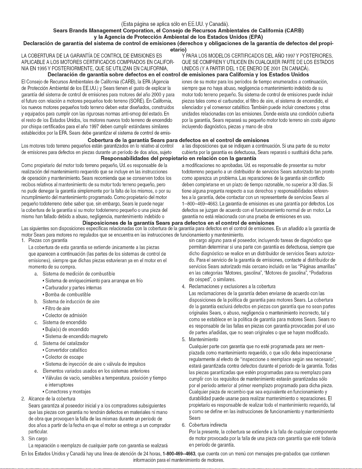
(Estap_.ginaseaplicas61oenEE.UU.yCanada.).
SearsBrandsManagement Corporation, el Consejo de Recursos Ambientales de California (CARB)
y la Agencia de Protecci6n Ambiental de los Estados Unidos (EPA)
Declaraci6n de garantia del sistema de control de emisiones (derechos y obligaciones de la garanfia de defectos del propi=
etario)
LA COBERTURADE LA GARANTJADE CONTROLDEEMISIONESES Y PARALOSMODELOSCERTIFICADOSDELANO 1997YPOSTERIORES,
APLIOABLEA LOS MOTORESCERTIFICADOSCOMPRADOSENCALIFOR- QUESE COMPRENY UTILICENENCUALQUIERPARTEDE LOSESTADOS
NIA EN 1995Y POSTERIORMENTE,QUESE UTILIZANENCALIFORNIA, UNIDOS(Y A PARTIRDEL 1 DE ENERODE2001 ENCANADA).
Declaraci6n de garanfia sobre defectos en el control de emisiones para California y los Estados Unidos
ElConsejode RecursosAmbientalesdeCalifornia(CARB),la EPA(Agencia
de Protecci6nAmbientalde los EE.UU.)y Searstienenel gusto de explicarla
garantiadel sistemade control de emisionesparamotoresdela_o 2000y para
elfuturo con relaci6na motorespeque_ostodo terreno(SORE).En California,
los nuevosmotorespeque_ostodo terrenodebenestar dise_ados,construidos
y equipadosparacumplircon las rigurosasnormasanti-smogdelestado.En
el restodelos EstadosUnidos,losmotoresnuevostodoterrenode encendido
porchispacertificadosparael a_o 1997debencumplirest_ndaressimilares
establecidospot la EPA.Sears debegarantizarel sistemade control de emis-
ionesde su motorpara losperiodosde tiempo enumeradosa continuaci6n,
siemprequeno hayaabuso,negligenciao mantenimientoindebidode su
motortodoterrenopeque_o.Su sistemade controldeemisionespuedeincluir
piezastalescomoel carburador,el filtro de aire, elsistemade encendido,el
silenciadoryel conversorcatalitico.Tambienpuedeincluirconectoresy otras
unidadesrelacionadascon lasemisiones.Dondeexistaunacondici6ncubierta
por la garantia,Searsreparar_su peque6omotortodo terrenosin costo alguno
incluyendodiagn6stico,piezasy manode obra
Cobertura de la garantJa Sears para defectos en el control de emJsiones
Los motorestodo terrenopeque6osest_ngarantizadosen Io relativoalcontrol a las disposicionesque se indiquena continuaci6n.Si una partede su motor
de emisionesparadefectosenpiezasduranteun periodode dos a_os,sujeto cubiertapot lagaranfiaes defectuosa,Sears reparar_o sustituir_dichaparte.
Responsabilidades del propietario en relacibn con la garantia
Comopropietariodel motortodo terrenopeque_o,Ud.es responsablede la
realizaci6ndel mantenimientorequeridoquese incluyeen las instrucciones
de operaci6ny mantenimiento.Searsrecomiendaquese conserventodoslos
recibosrelativosal mantenimientodesu motortodoterrenopeque_o,pero
no pude denegarla garantiasimplementepor la faltade los mismos,o por su
incumplimientodel mantenimientoprogramatic.Comopropietariodel motor
peque_otodoterrenodebe saberque, sinembargo,Searsle puedenegar
lacoberturade lagarantiasi su motortodoterrenopeque6oouna piezadel
mismohanfalladodebido a abuso,negligencia,mantenimientoindebidoo
a modificacionesno aprobadas.Ud.es responsablede presentarsu motor
todoterrenopeque6oa un distribuidorde serviciosSearsautorizadotan pronto
comoaparezcaun problema.Las reparacionesde la garantiasinconfiicto
debencompletarseen un plazode tiempo razonable,nosuperiora 30dias.Si
tienealguna preguntarespectoa sus derechosy responsabilidadesreferen-
tes a la garantia,debe contactarcon un representantede serviciosSearsal
1--800--469--4663.La garantiadeemisioneses unagarantiapor defectos.Los
defectosse juzgandeacuerdocon elfuncionamientonormalde unmotor.La
garantiano est_relacionadaconunapruebade emisionesen uso.
Disposiciones de la garantJa Sears para defectos en el control de emJsiones
Las siguientesson disposicionesespecificasrelacionadasconla coberturade lagarantia paradefectosen el controlde emisiones.Esun a_adidoa lagarantiade
motorSearspara motoresnoreguladosque seencuentraen lasinstruccionesde funcionamientoy mantenimiento.
1. Piezascon garantia
La coberturadeesta garantiase extiendeL]nicamentealas piezas
queaparecena continuaci6n(las partesde lossistemasde control de
emisiones),siempreque dichaspiezasestuvieranya en el motoren el
momentode su compra.
a. Sistemademedici6n de combustible
• Sistema deenriquecimientopara arranqueen frio
• Carburadory partesinternas
• Bombade combustible
b. Sistemadeinducci6nde aire
• Filtrode aire
• Colector de admisi6n
c. Sistemadeencendido
• Bujia(s)de encendido
• Sistema deencendidomagneto
d. Sistemadelcatalizador
• Convertidorcatalitico
• Colector de escape
• Sistema deinyecci6nde aireo v_lvulade impulsos
e. Elementosvariadosusadosen los sistemasanteriores
• Wlvulas de vacio,sensiblesa temperatura,posici6ny tiempo
e interruptores
• Conectoresy montajes
2. AIcancede la cobertura
Searsgarantizaal poseedorinicialy a loscompradoressubsiguientes
quelas piezas con garantianotendr_n defectosen materialesni mano
de obra que provoquenla falla de las mismasduranteun periodode
dos aSosa partirde la fechaen queel motorse entregaa un comprador
particular.
3. Sin cargo
La reparaci6no reemplazode cualquierpartecon garantiase realizar_
sin cargo alguno parael poseedor,incluyendotareasde diagn6sticoque
permitandeterminarsi una partecon garantiaes defectuosa,siempreque
dichodiagn6sticose realiceen un distribuidor de servicios Searsautoriza-
do. Parael serviciode lagarantia de emisiones,contacteal distribuidorde
serviciosSearsautorizadom_s cercanoincluidoen las"P_ginasamarillas"
en lascategorias"Motores,gasolina","Motoresde gasolina","Podadoras
de cesped",o similares.
4. Reclamacionesy exclusionesa la cobertura
Las reclamacionesde lagarantia debenenviarsedeacuerdocon las
disposicionesde la politica de garantiapara motoresSears.La cobertura
de lagarantia excluir_defectosen piezascon garantiaqueno scan partes
originalesSears,o abuso,negligenciao mantenimientoincorrecto,tal y
como se estableceen lapolitica degarantia para motoresSears.Sears no
es responsablede lasfallas enpiezas con garantia provocadaspor el uso
de partesa6adidas,que no scanoriginaleso quese hayan modificado.
5. Mantenimiento
Cualquierpartecon garantiaque no esteprogramadapara serreem-
plazadacomomantenimientorequerido,o que s61odebainspeccionarse
regularmentealefecto de"inspeccioneo reemplacesegL]nsea necesario",
estar_garantizadacontradefectosduranteel periodode la garantia.Todas
las piezasgarantizadasqueesten programadasparasu reemplazopara
cumplir con los requisitosde mantenimientoestar_ngarantizadass61o
por el periodoanterioral primerreemplazoprogramaticparadicha pieza.
Cualquierpiezade recambioquesea equivalenteen funcionamientoy
durabilidadpuedeusarse para realizarmantenimientoo reparaciones.El
propietarioes responsablede realizartodoel mantenimientorequerido,tal
y comose define en las instruccionesde funcionamientoy mantenimiento
Sears
6. Coberturaindirecta
Porla presente,la coberturase extiendea la falla de cualquiercomponente
de motorprovocadapot lafalla de unapiezacon garantiaque estetodavia
en periodode garantia.
En los EstadosUnidosy Canad_hay unalinea de atenci6nde 24 horas,1-800-469--4GG3,quecuentacon un menL]con mensajespre-grabadosque contienen
informaci6npara el mantenimientodemotores.
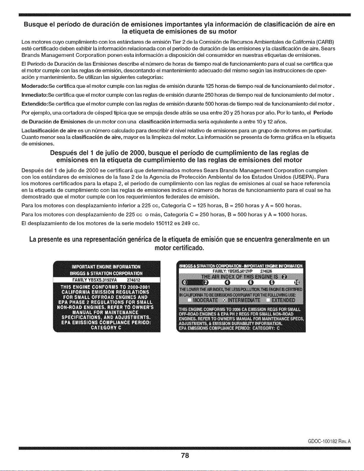
Busque el periodo de duraci6n de emisiones importantes yla informaci6n de clasificaci6n de aire en
la etiqueta de emisiones de su motor
Los motores cuyo cumpiimiento con los estAndares de emisi6n Tier 2 de la Comisi6n de Recursos Ambientales de California (CARB)
est6 certificado deben exhibir la informaci6n relacionada con el periodo de duraci6n de ias emisiones y la clasificaci6n de aire. Sears
Brands Management Corporation ponen esta informaci6n a disposici6n del consumidor en nuestras etiquetas de emisiones.
Ei Periodo de Duraci6n de las Emisiones describe el nQmero de horas de tiempo real de funcionamiento para el cuai se certifica que
el motor cumpie con ias reglas de emisi6n, descontando el mantenimiento adecuado del mismo segQn las instrucciones de oper-
aci6n y mantenimiento. Se utilizan las siguientes categonas:
Moderado:Se certifica que el motor cumpie con las reglas de emisi6n durante 125 horas de tiempo real de funcionamiento del motor.
Inmediato:Se certifica que el motor cumpie con las reglas de emisi6n durante 250 horas de tiempo real de funcionamiento del motor.
Extendido:Se certifica que el motor cumpie con las reglas de emisi6n durante 500 horas de tiempo real de funcionamiento del motor.
Por ejemplo, una cortadora de c6sped tJpica que se empuja desde arras se usa entre 20 y 25 horas por aSo. Por Io tanto, el Periodo
de Duraci6n de Emisiones de un motor con una clasificaci6n intermedia sena equivaiente a entre 10 y 12 aSos.
Laciasificaci6n de aire es un nQmero calculado para describir el nivel relativo de emisiones para un grupo de motores en particular.
Cuanto menor sea la clasificaci6n de aire, mayor es la limpieza del motor. La informaci6n se presenta de forma grAfica en la etiqueta
de emisiones.
Despu_s del 1 de julio de 2000, busque el periodo de cumplimiento de las reglas de
emisiones en la etiqueta de cumplimiento de las reglas de emisiones del motor
Despu6s del 1 de julio de 2000 se certificarA que determinados motores Sears Brands Management Corporation cumplen
con los estAndares de emisiones de la fase 2 de la Agencia de Protecci6n Ambientai de los Estados Unidos (USEPA). Para
los motores certificados para la etapa 2, el periodo de cumplimiento con ias reglas de emisiones al cual se hace referencia
en la etiqueta de cumplimiento con las reglas de emisiones indica el nQmero de horas de funcionamiento para el cual se ha
demostrado que el motor cumple con los requerimientos federales de emisi6n.
Para los motores con desplazamiento inferior a 225 cc, Categoria C = 125 horas, B = 250 horas y A = 500 horas.
Para los motores con desplazamiento de 225 cc o mAs, Categoria C = 250 horas, B = 500 horas y A = 1000 horas.
El desplazamiento de los motores de la serie modelo 150112 es 249 cc.
La presente es una representaci6n gen_rica de la etiqueta de emisi6n que se encuentra generaimente en un
motor certificado.
FAMILYYBSXS.3192VA 274812
GDOC-100182Rev.A
78

Felicitaciones por haber realizado una adquisici6n inteligente. El producto Craftsman® que ha
adquirido esta diseSado y fabricado para brindar muchos aSos de funcionamiento confiable. Pero
como todos los productos a veces puede requerir de reparaciones. Es en ese momento cuando el
disponer de un Acuerdo de protecci6n para reparaciones le puede ahorrar dinero y problemas.
A continuaci6n se detallan los puntos incluidos en el Acuerdo:
[] Servicio experto prestadopor nuestros 10,000 especialistas en reparaciones profesionales
[] Servicio ilirnitado sin cargo para las piezasy la mano de obra en todas las reparacionescubiertas
[] Reernplazo del producto hasta 1500 d61aressi no es posible reparar el producto cubierto
[] Descuento de 25% del precio normal del servicio y de las piezas relacionadas con el mismo que no esten cubiertas
por el acuerdo; ademas, 25% del precio normal de laverificaci6n de mantenimientopreventivo
[] Ayuda r_pida pot tel_fono - Io IlamamosResoluci6n RApida- el apoyo telef6nico de un Chamusca al representante.
Piense en nosotros como el manual "de un dueSohablador."
Una vez adquirido el Acuerdo, puede programar el servicio con tan s61orealizar una Ilamadatelef6nica. Puede Ilamaren
cualquier momento del dia o de la noche o programar un servicio en linea.
ElAcuerdo de Protecci6nde Reparaci6nes una compra sin riesgo. Si usted anula por alguna raz6n durante el periodo de
garantia de producto, proporcionaremos un reembolso Ileno.O, un reembolsoprorrateado en cualquier momentodespues
del periodo de garantia de producto expira, iAdquiera hoy su acuerdode protecci6n para reparaciones!
Se aplican determinadas limitaciones y exclusiones. Para obtener informaciTn adicional y precios en los Estados
Unidos Ilame al 1-800-827-6655.
El *Coverage en Canad_ivaria en algunos articulos. Para detalles Ilenos la Ilamada Chamusca Canad_ien 1-800-
361-8885.
Servicio de instalaci6n de Sears
Si desea solicitar la instalaci6n profesionalde Sears de aparatos domesticos, dispositivos paraabrir portones, calentado-
res de agua y otros articulos domesticos importantes, en los Estados Unidos o Canada flame al 1-800-4-MY-HOME®.
79

Your Home
For troubleshooting, product manuals and expert advice:
managernylife
www.managemylife.com
For repair - in your home - of all major brand appliances,
lawn and garden equipment, or heating and cooling systems,
no matter who made it, no matter who sold it!
For the replacement parts, accessories and
owner's manuals that you need to do-it-yourself.
For Sears professional installation of home appliances
and items like garage door openers and water heaters.
1-800-4-MY-HOME ® (1-800-469-4663)
Call anytime, day or night (U.S.A. and Canada)
www.sears.com www.sears.ca
Our Home
For repair of carry-in items like vacuums, lawn equipment,
and electronics, call anytime for the location of your nearest
Sears Parts & Repair Service Center
1-800-488-1222 (U.S.A.) 1-800-469-4663 (Canada)
www.sears.com www.sears.ca
To purchase a protection agreement on a product serviced by Sears:
1-800-827-6655 (U.S.A.) 1-800-361-6665 (Canada)
Para pedir servicio de reparaci6n
a domicilio, y para ordenar piezas:
1-888-SU-HOGAR ®
(1-888-784-6427)
www.sears.com
Au Canada pour service en frangais:
1-800-LE-FOYER Mc
(1-800-533-6937)
www.sears.ca
® Registered Trademark / TMTrademark of KCD IP, LLC in the United States, or Sears Brands, LLC in other countries
® Marca Registrada ! TMMarca de Fabrica de KCD IP, LLC en Estados Unidos, o Sears Brands, LLC in otros paises
MCMarque de commerce ! MDMarque deposee de Sears Brands, LLC